
 Open Access Article
 This Open Access Article is licensed under a Creative Commons Attribution-Non Commercial 3.0 Unported Licence
IrSi3As3: a first transition metal arsenide non-linear optical material†
Shannon J.
Lee
 abc,
Georgiy
Akopov‡
ab,
Adedoyin N.
Adeyemi
a,
Ernesto
Soto
ab,
Kui
Wu
d and
Kirill
Kovnir
*ab
abc,
Georgiy
Akopov‡
ab,
Adedoyin N.
Adeyemi
a,
Ernesto
Soto
ab,
Kui
Wu
d and
Kirill
Kovnir
*ab
aDepartment of Chemistry, Iowa State University, Ames, IA 50011, USA. E-mail: kovnir@iastate.edu
bAmes National Laboratory, U.S. Department of Energy, Ames, IA 50011, USA
cBrookhaven National Laboratory, U.S. Department of Energy, Upton, NY 11973, USA
dCollege of Chemistry and Environmental Science, Hebei University, Baoding 0710002, China
First published on 28th April 2023
Abstract
Noncentrosymmetric (NCS) silicon phosphides have recently shown promise as nonlinear optical materials due to the balance of strong second harmonic generation (SHG) activity and large laser damage threshold (LDT) values. While arsenides of electropositive metals, such as Ba, Mg, Zn, and Cd were explored, no NLO properties for transition metal tetrel arsenides have yet been reported. IrSi3As3 is a novel compound, isostructural to IrSi3P3, which allows a direct investigation on the impact of the heavier pnictogen on structural and optical properties. The direct bandgap is reduced from 1.8 eV for IrSi3P3 to 1.55 eV for IrSi3As3. Unlike many NLO chalcogenides, IrSi3As3 has a small bandgap without compromising the balance between SHG signal and high LDT values. IrSi3As3 was found to outperform both its phosphide analogue IrSi3P3, as well as the state-of-the-art infrared SHG standard AgGaS2 (AGS) in SHG activity and the LDT.
Introduction
Noncentrosymmetric (NCS) structures give rise to interesting physical phenomena and have been sought after in the condensed matter physics community. Reinvestigating M-Si-P phases to understand their structure–property relationships opens the door for the discovery of novel tetrel-pnictide materials with exciting physical properties. An example stems from the case of IrSi3P3, which was previously reported in the incorrect space group,1 then reinvestigated by our group and was found to have excellent nonlinear optical (NLO) properties.2 IrSi3P3 crystallizes in the polar monoclinic space group Cm. The exploration of the arsenide system resulted in the discovery of the first example of an ordered noncentrosymmetric (NCS) transition metal silicon arsenide, IrSi3As3. The other reported NCS transition metal silicon-arsenide, Fe5SiAs, crystallizing in the Ni5As2 structure type (P63cm space group), was reported to have random mixing of Si and As in all sites.3 The introduction of As into heavier metal silicides also resulted in mixed Si/As sites such as the centrosymmetric Mo5Si2As superconductor.4 Among 5d transition metals, only a few metals were reported to form silicon arsenides with the common formula MSiAs but drastically different structures for M = Hf, Ta, and M = Au.4–7 By using isovalent replacements of the pnictogen (P with As), the materials' properties can be adjusted. Novel metal silicon arsenides based on known metal silicon phosphides may be a successful approach to realize materials with symmetry-driven physical properties, such as second harmonic generation, topologically non-trivial phenomena, piezoelectricity, and superconductivity.2,5,8–15Tetrel pnictides have only been recently highlighted for their advantages as infrared-nonlinear optical (IR-NLO) materials,2,9,16,17 as compared to their more popular and much more studied chalcogenide counterparts. Synthetic methodology which we developed for phosphides, including the reaction of phosphorus with an atomically mixed refractory precursor, pre-melted M + Si, allowed the discovery of several previously inaccessible compounds.2,18,19 In this work we extended this methodology to arsenides. Based on the ease of synthesis and discovery of the title compound, IrSi3As3, it is expected that many other metal tetrel arsenides exist with likewise exciting properties. The structure–property relationships including crystal and electronic structures, and optical and transport properties of IrSi3As3 are reported.
Results and discussion
Crystal structures
IrSi3As3 crystallizes in the NCS monoclinic space group Cm (no. 8) with fully occupied sites. High-resolution single crystal X-ray diffraction (SCXRD) datasets were collected (sin![[thin space (1/6-em)]](https://www.rsc.org/images/entities/char_2009.gif) θmax/λ = 0.9 Å−1) and solved. The overall structural motif is similar to that of the P-containing analogue, IrSi3P3. Nevertheless, heavy twinning of the produced crystals resulted in relatively large R-values and differences in electron density peaks. To verify the produced structural model, a high-resolution synchrotron powder X-ray diffraction dataset was used for Rietveld refinement, which confirms the fully ordered crystal structure (Fig. S2 and Table S2†).
θmax/λ = 0.9 Å−1) and solved. The overall structural motif is similar to that of the P-containing analogue, IrSi3P3. Nevertheless, heavy twinning of the produced crystals resulted in relatively large R-values and differences in electron density peaks. To verify the produced structural model, a high-resolution synchrotron powder X-ray diffraction dataset was used for Rietveld refinement, which confirms the fully ordered crystal structure (Fig. S2 and Table S2†).
The crystal structure is composed of NCS fac-[IrSi3As3] octahedral units, with 3 Si atoms composing one face and 3 As atoms composing the other. These units are held together by Si–As bonds, packed into an extended NCS structure (Fig. 1). Energy dispersive X-ray spectroscopy (EDS) was used to confirm the composition of IrSi3As3. EDS shows an absence of foreign elements and resulted in the compositions of IrSi3.2(6)As3.1(4) averaged over several sites on different synthetic batches.
 | ||
| Fig. 1 Crystal structure of IrSi3As3 with the unit cell outlined in thin black lines showing Ir@Si3As3 octahedra highlighted in light purple (left) and a top-down view of the distorted octahedron emphasizing selected distances and angles (right). Ir: purple, Si: black, and As: pink. | ||
Assuming an ionic nature of metal–silicon and metal–arsenic bonds, i.e. a Zintl–Klemm counting scheme, each As atom forms three covalent bonds to Si thus being As0. In turn, Si atoms bonded to three arsenic atoms have a formal charge of −1. This leads to a +3 oxidation state for iridium: Ir3+(Si1−)3(As0)3. Due to the strong ligand field of a Si ligand, a low-spin closed-shell d6 configuration of Ir is expected, which is favorable for SHG materials.
The distortion of the octahedral unit is more extreme in the arsenide than in the phosphide structure (Fig. S1 and Table S1†). Crystallographic details are outlined in Table 1, showing a comparison of the previously published IrSi3P3 structure to the new IrSi3As3 reported here (showing both SCXRD and Rietveld refinement structural results). Although isostructural to the parent phase of IrSi3P3,2 the electronegativities and relative sizes of atoms in IrSi3As3 slightly change the bond distances observed in the structures. The Pauling electronegativity of Ir (2.20) is similar to that for P (2.19) and As (2.18).20 Silicon (1.90) is the most electropositive atom in the studied systems. The nonmetal covalent radii are also of consideration here; P (1.11 Å) is smaller than Si (1.17 Å) and As (1.22 Å). When Ir silicon phosphide and arsenide are compared, the interatomic Ir-Pn distances elongate (Table 2). In IrSi3As3, the Ir–Si (2.34–2.37 Å) bond distances are comparable to the those of Ir–Si (2.36–2.40 Å) in IrSi3P3, but Ir–As (2.52–2.64 Å) and Si–As (2.34–2.43 Å) distances are longer than Ir–P (2.41–2.51 Å) and Si–P (2.24–2.31 Å) ones in the structure of IrSi3P3. Furthermore, the Ir–Si bond distances of 2.34–2.37 Å are similar to bond distances found in binary metal silicide IrSi (2.32–2.56 Å).21
| IrSi3P32 | IrSi3As3 (SCXRD) | IrSi3As3 (Rietveld) | |
|---|---|---|---|
| Space group (no.) | Cm (no. 8) | Cm (no. 8) | Cm (no. 8) |
| Radiation (λ) | Mo Kα (0.71073 Å) | Mo Kα (0.71073 Å) | Synchrotron (0.45895 Å) |
| Temperature (K) | 100 | 100 | 295 |
| Z | 2 | 2 | 2 |
| Density, ρ (g cm−3) | 5.293 | 6.506 | 6.496 |
| a (Å) | 6.5895(3) | 6.8373(5) | 6.8476(1) |
| b (Å) | 7.2470(3) | 7.4722(5) | 7.47633(1) |
| c (Å) | 5.4916(3) | 5.6941(4) | 5.69156(9) |
| β (°) | 117.892(1) | 118.420(3) | 118.4270(2) |
| Vol. (Å3) | 232.78(2) | 255.85(3) | 256.2468(5) |
| Final R indices[all data] | R 1 = 0.013 | R 1 = 0.041 | χ 2 = 2.0 |
| wR 2 = 0.028 | wR 2 = 0.099 | wR = 10.7% | |
| μ (mm−1) | 30.425 | 45.88 | — |
| Data/parameters | 2059/38 | 1417/22 | — |
| Flack parameter | 0.01(1) | 0.10(1) | — |
| Goodness-of-fit | 1.06 | 1.13 | — |
| IrSi3P3 | IrSi3As3 | ||
|---|---|---|---|
| Distance (Å) | Distance (Å) | ||
| Ir–Si | 2.356(1) | Ir–Si | 2.335(4) |
| 2.406(3) | 2.372(6) | ||
| Ir–P | 2.404(1) | Ir–As | 2.523(3) |
| 2.512(3) | 2.641(2) | ||
| Si–P | 2.240(2) | Si–As | 2.432(7) |
| 2.287(2) | 2.391(3) | ||
| 2.288(2) | 2.341(4) | ||
| 2.306(5) | 2.405(4) | ||
Synthesis and thermal stability
The synthesis of the title compound was achieved via our developed strategy of atomically mixed precursors (arc-melted Ir + 3Si) to introduce both refractory elements into the reaction with As in close spatial and temporal proximity.2,19 Phase-pure samples were achieved as described in the Experimental section and characterized by powder X-ray diffraction (PXRD).Generally, metal silicon phosphides (with M/(Si + P) < 1) have high thermal stabilities (up to 1100 °C), whereas silicon arsenides, germanium phosphides, and germanium arsenides tend to have lower thermal stabilities, as was observed for the family of equimolar gold tetrel pnictides.5 Along this trend, IrSi3P3 exhibits no decomposition or melting up to 1100 °C, while IrSi3As3 decomposes at around 1060 °C (Fig. S3†) into binary iridium silicides and arsenides as confirmed by PXRD.
Electronic structures
Band structures and density of states (DOS) were calculated to predict electronic properties of IrSi3As3 using the tight binding-linear muffin tin orbital-atomic sphere approximation (TB-LMTO-ASA) code (Fig. 2).22 The band structure slightly changes for IrSi3As3 as compared to that for isostructural phosphide with an indirect bandgap of 1.05 eV, with the valence band maximum at the M point in the Brillouin zone and the conduction band minimum between the Γ and Z points. The direct bandgaps of 1.46 eV and 1.59 eV are seen at the L and V points, correspondingly (Table 3). | ||
| Fig. 2 Band structures and DOS for IrSi3As3 with Ir 5d, Si 3p, and As 4p atomic orbitals projected (16 × 16 × 16 k-mesh). | ||
| Direct (eV) | Indirect (eV) | ||
|---|---|---|---|
| LMTO | Optical | LMTO | Optical |
| 1.46 (L) | 1.55 | 1.05 (M, Z–Γ) | 1.20 |
| 1.59 (V) | |||
The DOS for IrSi3As3 is comparable to the DOS calculated for IrSi3P3.2 Strong hybridization of the Ir 5d and Si/As 3p/4p states is observed in both valence and conduction bands over a large energy range which suggests covalent Ir–Si and Ir–As bonding. The total DOS plots show a steep slope of states near the Fermi level, which is typically indicative of a high Seebeck coefficient. If the bandgap of another structural analogue can be further shrunk to a narrow gap (0.1–0.5 eV), perhaps by using heavier tetrel and pnictogen elements such as Ge or Sn and Sb or Bi, these materials may be efficient thermoelectrics.
Optical and transport properties
To verify the predicted bandgaps, diffuse reflectance measurements were conducted. Tauc plots for direct and indirect bandgaps are shown in Fig. 3, with IrSi3P3 shown for comparison. For IrSi3As3, the direct bandgap (1.55 eV) is larger than the indirect one (1.20 eV) in a good agreement with the calculated band structure (Table 3). Additionally, four-probe resistivity measurements were conducted on sintered pellets of IrSi3As3, which showed typical semiconducting temperature dependence (Fig. S4†).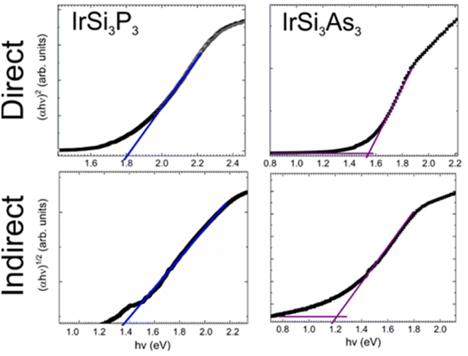 | ||
| Fig. 3 Tauc plots for direct and indirect optical bandgaps of IrSi3P3 and IrSi3As3. | ||
A powder sample of IrSi3As3 was measured using the Kurtz and Perry method with a Q-switch 2.09 μm laser source (3 Hz, 50 ns).23 Due to the smaller bandgap and long shortwave absorption edge of the material, the SHG signal may have been weakened. Regardless, IrSi3As3 outperformed the AGS standard at all probed particle sizes. IrSi3As3 did not show phase matchability due to the decreasing SHG signal at 88–105 μm (Fig. 4). Nevertheless, the sample showed a large SHG response compared to the current state-of-the-art standard of AgGaS2 (AGS) with a maximum signal of 1.7× AGS signal, which is similar to the response seen in a different experimental set-up for IrSi3P3 where the SHG response was 1.6× AGS signal. The signal is relatively robust for an arsenide phase with a smaller bandgap than for the phosphide phase. Further studies of the SHG efficiency with respect to variations of wavelength, frequency, and energy of incoming radiation will be possible after large optical quality single crystals of IrSi3P3 are produced.
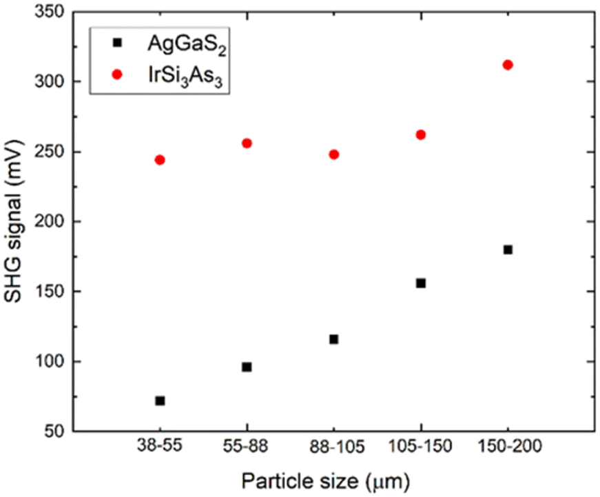 | ||
| Fig. 4 SHG activity vs. particle size for IrSi3As3 and AGS. | ||
The stability of the material under laser conditions is another important property for the application of nonlinear optics; the laser damage threshold (LDT). To evaluate LDT we used a short wavelength high-energy laser (1.06 μm10 Hz, 5 ns). IrSi3As3 has a high LDT value of 68 MW cm−2 compared to AGS with an LDT of 29.6 MW cm−2; ∼2.3× AGS. The main advantage of transition metal tetrel pnictides is the balance of good SHG with high LDTs at relatively small bandgaps (Table 4). Generally, chalcogenides have larger bandgaps and therefore larger SHG signals, but lack stability under laser irradiation.
| Composition | SHG/LDT (×AGS) |
|---|---|
| AgGaS2 (AGS) | 1.0/1.0 |
| IrSi3P3 | 1.6/1.6 |
| IrSi3As3 | 1.7/2.3 |
| MgSiAs2 | 0.6/1.1 |
| MnSiP2 | 6.0/2.4 |
Our work demonstrates the promise of arsenides for non-linear optical applications. Covalent metal–Si and metal–As bonding realized remarkable LDT properties – a feature unexpected for arsenides with a relatively small bandgap. Iridium is an expensive metal and materials containing iridium found use for niche applications. An importance of the current work is in the demonstration that the completely unexplored field of transition metal silicon–arsenides has promise for NLO applications due to lower meting points in comparison to corresponding phosphides, thus opening the possibilities for crystal growth, yet preserving excellent optical properties. In analogy with the development of earth-abundant substitutes for scarce Ir and Pt metals in homogeneous and electro-catalysis fields, one can expect that silicon-arsenides with more earth-abundant transition metals and outstanding NLO characteristics will be developed, which is a subject of undergoing research.
Experimental
Synthesis
Warning: The As vapor pressure produced at high temperatures may be sufficient to compromise the reaction ampoule and may lead to ampoule shattering. For related reactions, the amounts of toxic As should be kept to a minimum. Additionally, reaction ampoules may be wrapped in protective ceramic wool casings to limit the impact of potential ampoule breakage. Placing furnaces in a well-ventilated space, like a fumehood is highly recommended.All samples were prepared via solid–state reactions between a metal silicide precursor and arsenic powder (Alfa Aesar, 99.999%) without the use of flux or crystallizing agents. Each reaction was loaded into a fused silica ampoule, evacuated, flame-sealed, and then annealed in a muffle furnace at the profile specified below.
:Si = 1:3.1 to account for the evaporation of silicon. The samples were then placed in an arc-melter onto a copper hearth along with oxygen getter materials (zirconium metal). The arc-melter chamber was sealed and evacuated for 20 minutes followed by purging with argon; this process was repeated 3 times to ensure that no oxygen was present in the chamber. During arc-melting, the getters were melted first to ensure the absorbance of any trace oxygen, and then the samples were heated using a current of I ∼70 A until molten, and then allowed to solidify, flipped, and re-arced 2 more times to ensure homogeneity at a current of I ∼100 A. Powder X-ray diffraction (PXRD) shows that the products of the precursors were IrSi3.
:3 molar ratio for IrSi3As3. This heating profile involves a 14 hour ramp up to 800 °C, dwelling at that temperature for 72 hours, and then allowed to cool naturally back to room temperature. The product was a dark grey powder with a slightly brown tint.
X-ray diffraction
Powder X-ray diffraction (PXRD) was carried out on a Rigaku 600 Miniflex with Cu-Kα radiation with a Ni-Kβ filter. Single crystal X-ray diffraction (SCXRD) datasets were collected on a Bruker D8 Venture diffractometer with Mo-Kα radiation at 100 K. The data were collected with ω-scans at 0.3° step widths and integrated using the Bruker SAINT software package. The structure was determined and refined using the SHELX suite of programs.24 The FINDSYM program was used to determine Wyckoff positions.25,26High resolution synchrotron powder diffraction data were collected at beamline 11-BM at the Advanced Photon Source (APS), Argonne National Laboratory using an average wavelength of 0.45895 Å. A mixture of NIST standard reference materials, Si (SRM 640c) and Al2O3 (SRM 676) is used to calibrate the instrument, where the Si lattice constant determines the wavelength for each detector. Corrections are applied for detector sensitivity, 2θ offset, small differences in wavelength between detectors, and the source intensity, as noted by the ion chamber before merging the data into a single set of intensities evenly spaced in 2θ.27–29 Rietveld refinement was performed in CSAS-II software.30
Scanning electron microscopy (SEM)
Elemental analyses of powder and single crystal samples were performed using an FEI Quanta 250 field emission-SEM with energy dispersive X-ray spectroscopy (EDS) detection (Oxford X-Max 80) and Aztec software. Samples were mounted in epoxy, polished to a level surface, and coated with a conductive layer of carbon. The energy of the electron beam used was held constant at 15 kV.Differential scanning calorimetry (DSC)
DSC was used to determine each sample’s thermal stability. The samples were analyzed with a Netzsch DSC 404 F3 Pegasus. Approximately 20 mg of each phase-pure polycrystalline sample was sealed into an evacuated silica ampoule and measured against a blank. Both heating and cooling profiles were collected using a 10 K min−1 rate from 50 °C to 1100 °C.Solid state diffuse reflectance spectroscopy
Solid state UV-vis spectroscopy measurements were taken on a PerkinElmer Lambda 1050+ UV/Vis/NIR spectrometer equipped with a 150 mm Spectralon-coated integrating sphere. Finely ground samples were loaded into a powder holder equipped with a lens. The samples were pressed against the lens and held in place by a press and a spring within the holder. The holder was then placed at the reflectance port while the specular port was left open. The iris aperture was adjusted so that the sample beam was focused only on the samples. A sample holder containing a lens and Spectralon reference standard was used as a blank. The Kubelka–Munk conversion of the diffuse reflectance data was used to determine the bandgap of all the samples. Figures showing the band gap of the samples are expressed as Tauc plots.Second harmonic generation and laser damage threshold
Powder SHG responses were estimated via the Kurtz and Perry method,23,31 using a Q-switch laser (2.09 μm, 3 Hz, 50 ns) with different sample particle sizes, including 38–54, 54–88, 88–105, 105–150, and 150–200 μm. The as-grown high-quality AgGaS2 single crystal was ground by the Bridgman–Stockbarger method and sieved into the same size range as the reference. The laser damage thresholds (LDTs) were evaluated on a powder sample (150–200 μm) with a pulsed Nd:YAG laser (1.06 μm, 10 Hz, 5 ns). Similar size AgGaS2 is chosen as the reference. To adjust different laser beams, a 10 optical concave lens is added into the laser path. The damage spot is measured by the scale of an optical microscope.Spark plasma sintering (SPS)
Powders were well-ground under hexane, sieved through a 100-mesh screen, and then loaded into a 5 mm diameter graphite die, with WC plungers and graphite foil spacers. The SPS chamber was evacuated, and then partially filled with Ar gas to decrease the likelihood of arsenic outgassing. The pellet of IrSi3As3 was prepared by initially applying a pressure of 51 MPa, then heating to 400 °C over 5 minutes and further heating to 600 °C over 10 additional minutes. At the maximum temperature of 600 °C, the pressure was increased to 255 MPa and allowed to dwell for 10 minutes. This pressing profile resulted in a 60% geometrical relative density pellet.Resistivity measurements
Temperature dependence of electrical resistivity was measured on a sintered pellet of IrSi3As3 on a commercial multipurpose physical property measurement system (PPMS, Quantum Design). Electrical resistivity was measured from 150–300 K with a four-probe geometry using the alternating current transport option using 50 μm platinum wires and silver paste.Quantum chemical calculations: electronic structure
The band structures and density of states (DOS) of IrSi3As3 were calculated using the tight binding linear muffin tin orbital atomic sphere approximation (TB-LMTO-ASA) program.22 The calculations used basis sets of Ir (6s, 6p, 5d), Si (3s, 3p), and As (4s, 4p) atomic orbitals, with the Ir (5f), Si(3d), and As (4d) ones downfolded. The band structures and DOS of each structure were calculated after convergence of the total energy on a dense k-mesh of 16 × 16 × 16 points, with 2176 irreducible k points.Conclusions
Structures and properties were determined for IrSi3As3 and compared against those of IrSi3P3. Replacement of P with As resulted in shrinking of the direct bandgap from the 1.8 eV of IrSi3P3 to 1.5 eV for IrSi3As3. Nevertheless, the balance of the second harmonic generation signal and laser damage threshold is maintained and IrSi3As3 still outcompetes the state-of-the-art AgGaS2 standard by both characteristics. This work demonstrates that non-centrosymmetric transition metal tetrel arsenides may be viable nonlinear optical materials given their lower melting point than that of phosphides.Conflicts of interest
There are no conflicts to declare.Acknowledgements
Part of this work was supported by the Ames Laboratory's Laboratory Directed Research and Development (LDRD) program (S. L., G. A.). G. A. is grateful to the Ames Laboratory Spedding Postdoctoral Fellowship for financial support. Ames Laboratory is operated for the U. S. DOE by Iowa State University under contract # DE-AC02-07CH11358. E. S. and K. K. acknowledge support from the National Science Foundation under Grant No. 1955456. This research used resources of the Advanced Photon Source, a U. S. Department of Energy (DOE) Office of Science User Facility operated for the DOE Office of Science by the Argonne National Laboratory under Contract No. DE-AC02-06CH11357. We would like to thank Professor Julia Zaikina (Iowa State University) for access to the SPS instrument; Professor Vitalij Pecharsky (deceased) (US DOE Ames National Laboratory) for the use of the arc-melting setup; and Dr L. Ribaud and Dr S. Lapidus for help with conducting the high-resolution PXRD measurements at 11-BM (APS-ANL).References
- M. Kirschen, H. Vincent, Ch. Perrier, P. Chaudouet, B. Chenevier and R. Madar, Mater. Res. Bull., 1995, 30, 507–513 CrossRef CAS.
- S. Lee, S. L. Carnahan, G. Akopov, P. Yox, L.-L. Wang, A. J. Rossini, K. Wu and K. Kovnir, Adv. Funct. Mater., 2021, 31, 2010293 CrossRef CAS.
- M. Ellner and M. El-Boragy, J. Alloys Compd., 1992, 184, 131–138 CrossRef CAS.
- B.-B. Ruan, J.-N. Sun, M.-H. Zhou, Q.-S. Yang, Y.-D. Gu, G.-F. Chen, L. Shan and Z.-A. Ren, Inorg. Chem., 2022, 61, 10267–10271 CrossRef CAS PubMed.
- S. J. Lee, J. Won, L.-L. Wang, D. Jing, C. P. Harmer, J. Mark, G. Akopov and K. Kovnir, Chem. - Eur. J., 2021, 27, 7383–7390 CrossRef CAS PubMed.
- F. Hulliger, J. Less-Common Met., 1973, 30, 397–398 CrossRef CAS.
- C. Li, Y. Liu, W. Liu, J. Liu, X. Meng, Z. Lin and J. Yao, Inorg. Chem., 2021, 60, 18634–18638 CrossRef CAS PubMed.
- P. Narang, C. A. C. Garcia and C. Felser, Nat. Mater., 2020, 1–8 Search PubMed.
- K. E. Woo, J. Wang, K. Wu, K. Lee, J.-A. Dolyniuk, S. Pan and K. Kovnir, Adv. Funct. Mater., 2018, 28, 1801589 CrossRef.
- L. M. Schoop, F. Pielnhofer and B. V. Lotsch, Chem. Mater., 2018, 30, 3155–3176 CrossRef CAS.
- A. Iyo, I. Hase, H. Fujihisa, Y. Gotoh, N. Takeshita, S. Ishida, H. Ninomiya, Y. Yoshida, H. Eisaki and K. Kawashima, Phys. Rev. Mater., 2019, 3, 124802 CrossRef CAS.
- A. Kitaev, AIP Conf. Proc., 2009, 1134, 22–30 CrossRef CAS.
- S. N. Rashkeev, S. Limpijumnong and W. R. L. Lambrecht, Phys. Rev. B, 1999, 59, 2737–2748 CrossRef CAS.
- S. C. Abrahams and J. L. Bernstein, J. Chem. Phys., 1971, 55, 796–803 CrossRef CAS.
- S. C. Abrahams, R. L. Barns, J. L. Bernstein and E. H. Turner, Solid State Commun., 1974, 15, 737–739 CrossRef CAS.
- J. Mark, J. Wang, K. Wu, J. G. Lo, S. Lee and K. Kovnir, J. Am. Chem. Soc., 2019, 141, 11976–11983 CrossRef CAS PubMed.
- H.-D. Yang, M.-Y. Ran, W.-B. Wei, X.-T. Wu, H. Lin and Q.-L. Zhu, Chem.–Asian J., 2021, 16, 3299–3310 CrossRef CAS PubMed.
- G. Akopov, N. W. Hewage, P. Yox, G. Viswanathan, S. J. Lee, L. P. Hulsebosch, S. D. Cady, A. L. Paterson, F. A. Perras, W. Xu, K. Wu, Y. Mudryk and K. Kovnir, Chem. Sci., 2021, 12, 14718–14730 RSC.
- G. Akopov, J. Mark, G. Viswanathan, S. J. Lee, B. C. McBride, J. Won, F. A. Perras, A. L. Paterson, B. Yuan, S. Sen, A. N. Adeyemi, F. Zhang, C.-Z. Wang, K.-M. Ho, G. J. Miller and K. Kovnir, Dalton Trans., 2021, 50, 6463–6476 RSC.
- L. Pauling, The Nature of the Chemical Bond and the Structure of Molecules and Crystals : an Introduction to Modern Structural Chemistry, Ithaca, N.Y., Cornell University Press, 1960 Search PubMed.
- K. Göransson, I. Engström and B. Noläng, J. Alloys Compd., 1995, 219, 107–110 CrossRef.
- O. Jepsen, A. Burkhardt and O. K. Andersen, 1999.
- S. K. Kurtz and T. T. Perry, J. Appl. Phys., 1968, 39, 3798–3813 CrossRef CAS.
- G. M. Sheldrick, Acta Crystallogr., Sect. A: Found. Crystallogr., 2008, 64, 112–122 CrossRef CAS PubMed.
- H. T. Stokes and D. M. Hatch, J. Appl. Crystallogr., 2005, 38, 237–238 CrossRef CAS.
- H. T. Stokes, D. M. Hatch, and B. J. Campbell, FINDSYM, ISOTROPY Software Suite, https://iso.byu.edu, accessed in 2022 Search PubMed.
- J. Wang, B. H. Toby, P. L. Lee, L. Ribaud, S. M. Antao, C. Kurtz, M. Ramanathan, R. B. Von Dreele and M. A. Beno, Rev. Sci. Instrum., 2008, 79, 085105 CrossRef PubMed.
- P. L. Lee, D. Shu, M. Ramanathan, C. Preissner, J. Wang, M. A. Beno, R. B. Von Dreele, L. Ribaud, C. Kurtz, S. M. Antao, X. Jiao and B. H. Toby, J. Synchrotron Radiat., 2008, 15, 427–432 CrossRef CAS PubMed.
- L. R. Dalesio, J. O. Hill, M. Kraimer, S. Lewis, D. Murray, S. Hunt, W. Watson, M. Clausen and J. Dalesio, Nucl. Instrum. Methods Phys. Res., 1994, 352, 179–184 CrossRef CAS.
- B. H. Toby and R. B. Von Dreele, J. Appl. Crystallogr., 2013, 46, 544–549 CrossRef CAS.
- D. J. Clark, J.-H. Zhang, A. J. Craig, A. Weiland, J. A. Brant, J. B. Cho, Y. S. Kim, J. I. Jang and J. A. Aitken, J. Alloys Compd., 2022, 917, 165381 CrossRef CAS.
Footnotes |
| † Electronic supplementary information (ESI) available. See DOI: https://doi.org/10.1039/d2ta09313h |
| ‡ Current address – Department of Chemistry, Rutgers University-Newark, Newark, NJ 07102, USA. |
| This journal is © The Royal Society of Chemistry 2023 |