
 Open Access Article
 This Open Access Article is licensed under a Creative Commons Attribution-Non Commercial 3.0 Unported Licence
Clickable polymer scaffolds enable Ce recovery with peptide ligands†
Jacob D.
Hostert
 ,
Maura R.
Sepesy
,
Christine E.
Duval
* and
Julie N.
Renner
*
,
Maura R.
Sepesy
,
Christine E.
Duval
* and
Julie N.
Renner
*
Chemical and Biomolecular Engineering, Case Western Reserve University, 2102 Adelbert Rd, Cleveland, Ohio, USA. E-mail: christine.duval@case.edu; julie.renner@case.edu
First published on 31st March 2023
Abstract
Rare earth elements (REEs) are a vital part of many technologies with particular importance to the renewable energy sector and there is a pressing need for environmentally friendly and sustainable processes to recover and recycle them from waste streams. Functionalized polymer scaffolds are a promising means to recover REEs due to the ability to engineer both transport properties of the porous material and specificity for target ions. In this work, REE adsorbing polymer scaffolds were synthesized by first introducing poly(glycidyl methacrylate) (GMA) brushes onto porous polyvinylidene fluoride (PVDF) surface through activator generated electron transfer atom transfer radical polymerization (AGET ATRP). Azide moieties were then introduced through a ring opening reaction of GMA. Subsequently, REE-binding peptides were conjugated to the polymer surface through copper catalyzed azide alkyne cycloaddition (CuAAC) click chemistry. The presence of GMA, azide, and peptide was confirmed through Fourier transform infrared spectroscopy. Polymer scaffolds functionalized with the REE-binding peptide bound cerium, while polymer scaffolds functionalized with a scrambled control peptide bound significantly less cerium. Importantly, this study shows that the REE binding peptide retains its functionality when bound to a polymer surface. The conjugation strategy employed in this work can be used to introduce peptides onto other polymeric surfaces and tailor surface specificity for a wide variety of ions and small molecules.
1. Introduction
Rare earth elements (REEs) are key components of many technological applications, such as: batteries, solar panels, superconductors, catalytic converters, and supermagnets.1 The majority of REEs are in the lanthanide series, with cerium being the most abundant.2 Fly ash and coal-combustion plant wastewater are promising sources of these elements, with acid extraction being used to leach REEs from solid waste.3 The resultant leachate and wastewater typically have low concentrations of these elements (3–7 ppm), and separation is difficult due to the similar size and chemical properties of REEs.3,4 The industry standard for REE purification after mining ore is to use inefficient multistage liquid-liquid extractions.5Currently, separation technology to recover REEs is underdeveloped – fewer than 1% of REEs are sourced through recycling, despite there being no domestic supply of these elements in the United States.6 Efforts to recover REEs often are on the laboratory scale and have focused on liquid-liquid extraction,5,7 separation using ionic liquids,8,9 polymeric resins,10,11 and nanofiltration membranes.12 However, liquid-phase strategies like liquid-liquid extraction and ionic liquids are disadvantageous due to production of large volumes of hazardous waste. Solid phase strategies like polymeric resins and membrane technologies produce less waste while also having more facile operation requirements, like fewer processing steps. Among the solid phase techniques for REE recovery, membranes are attractive due to the high flow rates possible during separation in comparison to resin columns. Typical nanofiltration membranes achieve separation via ion size, yet most of the REEs are of similar size. The inability to differentiate between ions of similar size in state-of-the-art nanofiltration membranes limits their applications in selective separations.
Membrane adsorbers are a promising way to achieve high selectivity without sacrificing throughput. Membrane adsorbers consist of an ultra- or microfiltration membrane coated with ligands which are designed to bind with specific analytes (ions or molecules). Typically, the coatings are physisorbed polymer networks or covalently bound polymer brushes. One facile route to creating a membrane adsorber is through grafting poly(glycidyl methacrylate) from the membrane surface, thus introducing an epoxide ring onto the membrane.13 The reactivity of the epoxide can then be leveraged to introduce a variety of functional groups onto the membrane surface such as: enzymes, peptides, and azides.14–19 In this work, we move towards creating membrane adsorbers by developing the chemistry to introduce ligands for REE recovery onto polymer scaffolds and confirming the ligand retains the ability to recover REEs after attachment.
Particularly promising ligands for REE recovery are peptides – relatively short polymeric chains of amino acids, which if arranged in a specific sequence can have high binding specificity for an ion or small molecule. Synthetic peptide manufacturing has become feasible at the large scale20 required for peptide-functionalized separations, making peptides a promising, cheaper alternative to larger proteins.21 Peptide sequences following an EF-hand motif, have been shown to have high affinity for REEs.22–27
Proteins with EF-hand sequences have been shown to be robust in relevant industrial conditions (low pH, with competing ions) binding specifically to REEs at a pH as low as 3.7, and showing REE complex stability in a large temperature range (from 25 °C to 85 °C).28 Thus, peptides have the potential to be robust in low pH and high temperature conditions. A previously identified peptide obtained from the EF-hand loop of calmodulin (DKDGDGTITTKE) has been shown to have high affinity for Ce(III) ions in solution and when tethered to a gold surface.29,30 However, this peptide has never been conjugated to polymer scaffold. Introduction of peptides onto a polymer scaffold surface has largely been employed for cell recognition,14,16 but not for metal ion adsorption. Technology which enables the use of peptides on polymer scaffolds would be useful for REE capture as well as: phosphate capture,29 antimicrobial coatings,31 copper and zinc capture,32 and precious metal capture.33 Current state-of-the-art technology for bio-inspired REE recovery focuses on column separations using whole lanmodulin protein34 – while this strategy may be effective, peptides can potentially be attached at higher densities on a separation material due to their smaller size (∼1600 Da for peptide, ∼12![[thin space (1/6-em)]](https://www.rsc.org/images/entities/char_2009.gif) 000 Da for lanmodulin35). Our previous study demonstrated the ability of gold-bound peptide to capture REEs,29 however a gold surface likely has limited applications. Evaluating realistic separation materials is of key interest for peptide-based REE capture. It is not known which materials these peptides will be compatible with, specifically which materials allow the peptides to maintain their REE binding functionality.
000 Da for lanmodulin35). Our previous study demonstrated the ability of gold-bound peptide to capture REEs,29 however a gold surface likely has limited applications. Evaluating realistic separation materials is of key interest for peptide-based REE capture. It is not known which materials these peptides will be compatible with, specifically which materials allow the peptides to maintain their REE binding functionality.
In this work, we characterize a polymer scaffold functionalized with an affinity peptide for REE recovery from dilute solutions, for the first time. Specifically, we demonstrate the utility of a calmodulin-derived EF-hand peptide conjugated to a polymer scaffold for capture of cerium(III) (Ce3+) ions. We employ a poly(GMA)-grafted polyvinylidene difluoride (PVDF) membrane as our polymer scaffold. Copper catalyzed azide-alkyne cycloaddition (CuAAC), a type of click chemistry, was employed to join the peptide to the polymer. This chemistry has the advantages of being selective, irreversible, and non-reactive to biologic compounds while still being fast enough for roll-to-roll manufacturing.36,37 Epoxide groups in the polymer brushes can be readily reacted to install azide groups on the surface, and peptides can be modified with propargylglycine (Pra, an unnatural amino acid) to include an alkyne functional group. Introducing a source of copper(I) ions allows for the CuAAC reaction to proceed and tether peptide to the polymer scaffold, shown in Fig. 1. Thus, the goal of this study was to fabricate a peptide-functionalized polymer scaffold using CuAAC click chemistry, characterize the material via attenuated total reflectance Fourier-transform infrared spectroscopy (ATR-FTIR), visualize the material via confocal microscopy, and test the ability of the material to adsorb Ce3+ ions. A key outcome of this study is determining whether the REE binding peptide maintains its functionality when immobilized on a polymer surface and visualizing the location of the peptides within the membrane. In meeting these goals, the study aims to demonstrate the potential that peptides hold as advanced REE separation tools in combination with polymer scaffolds.
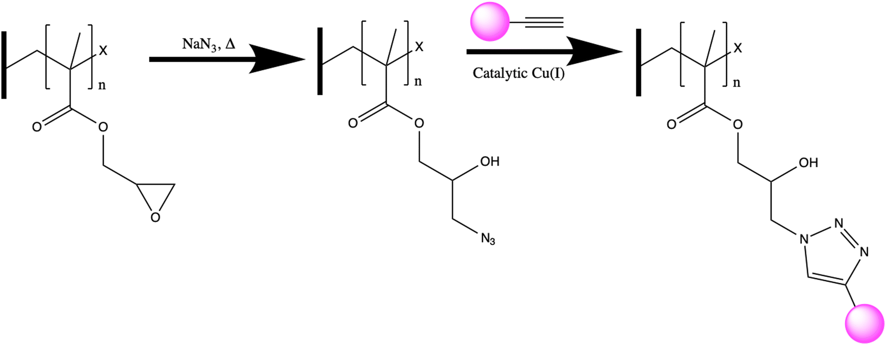 | ||
| Fig. 1 Polymer scaffold functionalization: first, an azide group is covalently attached to the GMA-grafted PVDF scaffolds through a ring opening reaction. Next, an alkyne labeled molecule (pink circle) – either alkyne labeled peptide or alkyne labeled fluorescein derivative in this work – is clicked onto the surface using catalytic copper(I). | ||
2. Materials and methods
2.1. Materials
Deionized water (DI H2O) was obtained from Western Reserve Water Systems mixed deionizer tanks (10 MΩ). Polyvinylidene difluoride (PVDF) membranes of 47 mm diameter and 0.22 μm pore diameter were obtained from MilliporeSigma (Durapore, Cat. No. GVWP04700). Cerium(III) chloride heptahydrate (99.9% trace metal basis) was purchased from Sigma-Aldrich. Inhibitors were removed from monomers using aluminum(II) oxide (activated, basic, Brockmann I, Sigma Aldrich) in a glass column. AGET ATRP used glycidyl methacrylate (GMA, ≥97%, Sigma Aldrich) monomer, 1,1,4,7,7-pentamethyldiethylenetriamine (PMDETA, 98+%, Acros Organics), copper(II) chloride (CuCl2, ultra-dry, ≥99.995% metal basis, Alfa Aesar™) and industrial grade nitrogen gas (size 300 cylinder, CGA-580, Airgas Great Lakes Inc.). Membranes were washed with methanol (CERT ACS/HPLC, ≥99%, Fisher Chemical), ethylenediamine tetraacetic acid (EDTA) (Fisher), and hydrochloric acid (OptimaTM, Fisher Chemical). Ammonium chloride and sodium azide were obtained from DOT Scientific, ascorbic acid was obtained from Acros Organics, and copper(II) sulfate was obtained from Sigma Aldrich. A previously identified cerium-binding peptide sequence30 was modified with the nonnatural amino acid propargylglycine (Pra) and ordered from Genscript at >95% purity (sequence: Pra-GGGDKDGDGTITTKE, with N-terminal acetylation and C-terminal amidation). FAM alkyne 6 isomer was obtained from Lumiprobe. This peptide is referred to as EF-hand peptide or EF peptide throughout the text. A scrambled version was also designed as a control with a sequence consisting of Pra-GGGTDGGDTDKTEIK, also with N-terminal acetylation and C-terminal amidation. The scrambled version of the peptide is called scrambled EF-hand peptide, or scrambled EF peptide.2.2. Polymer scaffold functionalization
After one hour, the stopper was removed from the flask, letting in oxygen, and slowing the polymerization reaction. The poly(GMA) PVDF membrane was removed from the flask and placed in 30 mL of an equal parts by volume methanol:water solution where it was rinsed on the shaker table for 24 hours. This rinse fully stops the reaction and starts the removal of the residual reactants from the poly(GMA) membrane. After the initial rinse, the 1:1 methanol:water solution was replaced and the membrane was sonicated for 30 minutes in 20 mL of the new solution. Finally, the rinsed membrane was dried at room temperature in a Fisher-brand Isotemp vacuum oven with a pressure range of 34–85 kPa using a Fisher Scientific MaximaDry pump. Once the membrane's weight was consistent, indicating all physisorbed polymer was washed away, the dried membrane was placed in a 3′′ × 3′′ bag for storage and later ring-opening functionalization.
2.3. Polymer scaffold characterization
2.4. Adsorption behavior
Adsorption experiments were conducted by immersing single peptide-functionalized polymer scaffold samples (∼1 mg) in 1 mL ion-containing solutions in 2 mL microcentrifuge tubes (Thermo Fisher Scientific). Polymer scaffold-containing solutions were equilibrated at room temperature for 24 h on a shaker table at 160 rpm. Adsorption experiments were conducted at least three times for each peptide using different polymer scaffolds prepared by the same technique. This approach allowed us to account for batch-to-batch variability of the polymer scaffolds. The initial and equilibrium liquid phase concentrations of Ce3+ were measured by UV-visible spectrophotometry using a Molecular Devices Spectramax M2 plate reader and calcium arsenazo III as an indicator. 200 μL of calcium arsenazo III was added to each well in a 96-well plate, and 100 μL of cerium containing samples were added to individual wells – the pH of each well was 8.2. Arsenazo III is known to form a complex with lanthanides that absorbs at 652 nm at this pH.39,40 Each well was mixed via pipetting up and down before immediately measuring the absorbance at 652 nm. A calibration curve was first measured, showing a linear correlation between absorbance and cerium concentration (Fig. S1, ESI†).
The equilibrium binding capacity (Qe) was calculated after determining solution concentration according to eqn (1).
 | (1) |
2.5. Statistical analysis
Statistical hypothesis testing was performed using Minitab with α = 0.05. Analysis of variance (ANOVA) was performed on FTIR peak ratio (2990 cm−1/1650 cm−1; –CH3/amide II) data, followed by Tukey's post hoc testing. A two-sample t-test was performed on equilibrium binding capacity data, and FTIR peak ratio (2990 cm−1/2100 cm−1; –CH3/–N3) data. Normality and equal variance were assumed in all statistical tests. Simple linear regression was performed using Origin to obtain the best fit line for the cerium calibration curve using an arsenazo assay.3. Results and discussion
3.1. Polymer scaffold functionalization
GMA-functionalized membranes were selected due to the ease of performing a ring opening reaction to covalently introduce functionality to the polymer scaffold – in this study, azide functional groups. To determine if GMA was successfully grafted from the polymer scaffold, ATR-FTIR was conducted on both an unmodified and a GMA-modified polymer scaffold – shown in purple and blue, respectively in Fig. 2. The appearance of a strong peak at 1700 cm−1 associated with carbonyl C![[double bond, length as m-dash]](https://www.rsc.org/images/entities/char_e001.gif) O stretching and the peak at 910 cm−1 corresponding to the epoxide ring support the successful attachment of GMA to the polymer scaffold via AGET ATRP.39
O stretching and the peak at 910 cm−1 corresponding to the epoxide ring support the successful attachment of GMA to the polymer scaffold via AGET ATRP.39
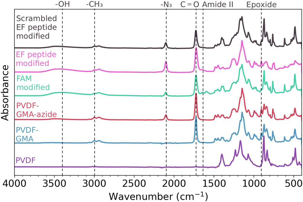 | ||
| Fig. 2 Representative FTIR spectra confirm the presence of specific functional groups along each successive step of the functionalization. From bottom to top: the purple spectrum corresponds to an unmodified PVDF sample, the blue spectrum corresponds to a poly(GMA) PVDF polymer scaffold, the red spectrum corresponds to a poly(GMA) PVDF polymer scaffold after a ring opening with sodium azide, the green spectrum corresponds to alkyne labeled fluorophore (FAM alkyne 6 isomer) ‘clicked’ onto the polymer scaffold, the pink spectrum corresponds to alkyne labeled EF-hand peptide ‘clicked’ onto the polymer scaffold, and the black spectrum corresponds to alkyne labeled scrambled EF-hand peptide ‘clicked’ onto the polymer scaffold. | ||
After successful functionalization with GMA, azide groups were then attached on the polymer scaffold through a ring opening reaction of the epoxide, shown in Fig. 1. The presence of azide on the polymer scaffold was confirmed through FTIR, seen in the red spectrum of Fig. 2. The appearance of the peak at 2100 cm−1 is indicative of asymmetric stretching of azide functional groups,41 and the appearance of a broad peak centered around 3400 cm−1 indicates the appearance of hydroxyl groups from the ring opening reaction.
To assess the distribution of azide sites accessible for the CuAAC (‘click’) reaction, shown in Fig. 1, we next attached an alkyne labeled fluorescein derivative (FAM alkyne) to the polymer surface to later be analyzed via confocal microscopy. The successful attachment of FAM alkyne (structure shown in Fig. S2, ESI†) was confirmed through FTIR, as seen in green in Fig. 2. The -OH peak centered on 3400 cm−1 also increased in intensity after attachment of FAM alkyne due to the presence of these groups on the fluorophore. Peaks appearing at 1600 cm−1 and 1550 cm−1 are due to xanthene ring C–C stretching containing conjugated carbonyl bands and asymmetric carboxylate stretching.42
Alkyne functionalized EF-hand peptide was also installed on the polymer surface through ‘click’ chemistry and confirmed through FTIR – represented by the pink spectrum in Fig. 2. The absorbance of specific peaks was variable due to inhomogeneities in scaffold production, thus peak ratios were employed to compare relative magnitudes. Peaks may appear smaller or larger when visually comparing the spectra, but computing peak ratios make the relative changes in magnitude clear – even when perceived magnitudes are small. Peak ratios have been previously employed for analysis of peptides on surfaces43 and for analysis of functional groups on polymeric surfaces.38 After the peptide was added to the polymer scaffold, the peak ratio of –CH3:N3 significantly increased (Fig. S3, ESI†) indicating the click reaction proceeded as expected, where the methyl groups should remain constant while the azide peaks disappear during the ‘click’ reaction. While the –CH3:N3 peak ratios suggest the CuAAC reaction did occur, the azide peak at 2100 cm−1 did not disappear completely. While other studies have shown the complete absence of the azide peak post reaction,14,44 we speculate that the continued presence of this peak is due to the inaccessibility of some reaction sites to the CuAAC reaction. The azide molecule is smaller than both FAM alkyne and the peptide used in this study, so azide groups will likely have better transport to more reaction sites on the surface of the polymer scaffold. The peak centered at 1650 cm−1 is the amide I band, indicative of the CO stretching vibration of the peptide backbone.45 Overall, the FTIR shown in Fig. 2 supports that the sequential addition of GMA, azide, and alkyne labeled molecules was successful.
To further quantify the FTIR results we analyzed the peak ratio of the –CH3 peak (2990 cm−1) of GMA to amide II (1650 cm−1), shown in Fig. 3. The –CH3 peak will remain unchanged throughout the reactions, while the amide II peak should increase as the ‘click’ reaction proceeds leading to a decrease in peak ratio. For EF-hand peptide and scrambled EF-hand peptide functionalized polymer scaffolds, a decrease in peak ratio compared to azide functionalized polymer scaffolds was seen, indicating the ‘click’ reaction proceeded as expected. Furthermore, there was not a significant difference in peak ratio between the EF-hand peptide and scrambled EF-hand peptide groups, implying that performance differences that may be observed between those two groups for REE adsorption could not be attributed to differences in the amount of peptide. The variability seen in Fig. 3 was likely due to the inhomogeneous nature of GMA-modified polymer scaffolds.
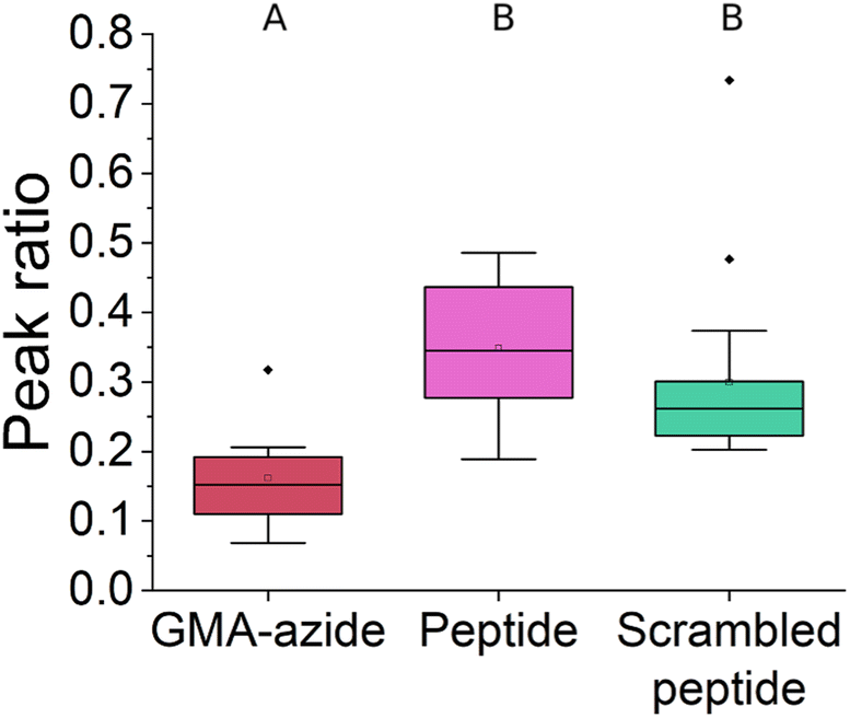 | ||
| Fig. 3 FTIR peak ratios (2990 cm−1/1650 cm−1; –CH3/amide II) of different polymer scaffolds characterized in this study. The peak ratio represents the extent to which the click reaction proceeds – the amide II peak will appear as the reaction proceeds while the –CH3 peak should remain unchanged. Data are represented by box and whisker plots. Whiskers represent the maximum and minimum values, excluding outliers. Significant differences were determined by performing ANOVA and the Tukey's post hoc test in Minitab assuming equal variances. Multiple separate samples were analyzed such that n = 8 for GMA-azide, n = 27 for EF-hand peptide and n = 19 for scrambled EF-hand peptide. Groups that do not share a letter are statistically different (p < 0.05). Peptide and scrambled peptide in this figure refer to the EF-hand and scrambled EF-hand peptide sequences, respectively. | ||
3.2. Polymer scaffold characterization
The inclusion of the FAM alkyne on the polymer scaffold surface allowed for qualitative assessment of the distribution of accessible reaction sites by illuminating the sample with 470 nm blue light (shown in Fig. S4, ESI†). FAM alkyne fluoresces under blue light, and fluorescence was observed across the polymer scaffold surface. To further assess the distribution of FAM alkyne throughout the thickness of the polymer scaffold, confocal microscopy was used on polymer scaffold sections. Fig. 4a shows a representative composite confocal microscopy image with most fluorescence localized to the surface of the polymer scaffold. The fluorescence imaging revealed that the CuAAC reaction was able to take place at least 3 μm into the depth of the polymer scaffold, as shown in Fig. S5 (ESI†). It was observed that fluorescence intensity diminished the further into the polymer scaffold confocal slices were taken. A study by Charcosset and Bernengo reported that confocal microscopy can probe up to 6 μm below the surface of a PVDF membrane before the signal becomes weak.46 As our study notes fluorescence up to 3 μm below the surface, our functionalized region falls within the penetration depth of confocal microscopy for PVDF. Poly(GMA) PVDF polymer scaffolds after ring opening with sodium azide were also mixed with FAM alkyne with no Cu catalyst to ensure the observed fluorescence was not simply due to physical adsorption. These polymer scaffolds were not able to be imaged via confocal microscopy, as there was no fluorescence detected.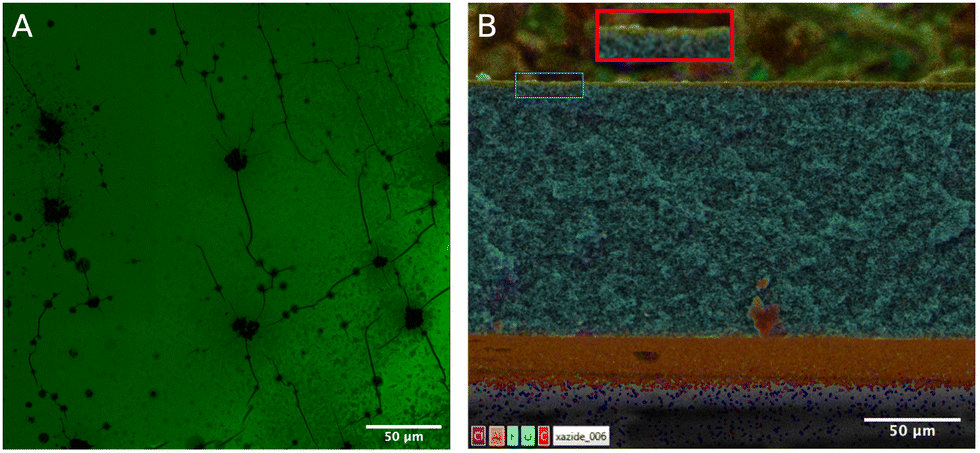 | ||
| Fig. 4 Microscopy of polymer scaffolds prepared in this study. (A) Confocal microscopy images of alkyne labeled fluorophore (FAM alkyne 6 isomer) ‘clicked’ onto the polymer scaffold. Microscopy illuminates the composition and morphology of the polymer scaffold – the green areas are regions the FAM-6 alkyne successfully clicked on the polymer scaffold, while black areas remain unmodified. (B) SEM EDS imaging of a polymer scaffold cross section. The red box is a 2× zoomed in version of the region in the blue box. | ||
The morphology of peptide-modified polymer scaffolds was then investigated through SEM EDS, as shown in Fig. 4b. The majority of the cross section is pristine PVDF, evidenced by the abundance of fluorine. At the surface of the cross section, there is an abundance of oxygen resulting from GMA being grafted from the PVDF polymer scaffold (a 2× zoomed in version is shown in the red box). This oxygen-rich region is where azide and thus alkyne-functionalized molecules can be attached. Image analysis shows that this oxygen-rich area penetrates roughly 2.7 μm into the polymer scaffold surface, corroborating the confocal microscopy results.
Overall, the combined spectroscopy and imaging results demonstrate successful EF-hand peptide attachment while also highlighting the need to optimize and control porosity, homogeneity and morphology of the polymer scaffold materials. More complete functionalization through the thickness of the scaffold (i.e., beyond 3 μm) will likely lead to higher REE capture. If the ATRP reaction was initiated directly from the PVDF backbone,47–49 then there may be transport limitations during the AGET ATRP reaction that prevent grafting from the internal surface area and pores. An alternative explanation for the surface-localized functional layer is that the ATRP reaction was initiated from the proprietary hydrophilic coating which is present on both sides of the PVDF (Durapore) membrane.50,51 In either case, functionalization was limited to the surface which ultimately limits the ion adsorption capacity per scaffold.
3.3. Adsorption of REE to functionalized polymer
Prior studies have examined the cerium binding behavior of the EF-hand peptide on gold surfaces but have not explored porous polymer materials.29,30 Equilibrium adsorption experiments were conducted to confirm whether the EF-hand peptide retained its functionality (i.e. ability to bind cerium) when conjugated to a polymer scaffold. The cerium solution pH was adjusted to 7 to ensure peptide stability. Because peptides have multiple pKa values due to their termini and various side chains,52 the overall charge of the peptide at a pH of 7 is −2. The results of the equilibrium adsorption experiment are summarized in Fig. 5, with an initial cerium concentration of 15 ppm.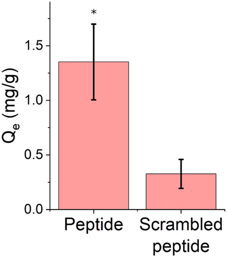 | ||
| Fig. 5 Equilibrium adsorption data for 15 ppm Ce3+ on peptide functionalized polymer scaffolds. Data are represented as the mean ± standard deviation with n = 6. Qe is the binding capacity, as defined in eqn (1). (*) represents p < 0.05 compared to scrambled EF-hand peptide, using a two-sample t-test performed in Minitab assuming equal variance. Peptide and scrambled peptide in this figure refer to the EF-hand and scrambled EF-hand peptide sequences, respectively. | ||
The amount of cerium adsorbed to the EF-hand peptide-functionalized polymer scaffold was significantly higher than the scrambled EF-hand peptide-functionalized polymer scaffold. Our previous studies show that this peptide binds cerium when tethered to a gold surface at concentrations as low as 0.5 ppm,30 at a pH as low as 3, at a pH as high as 7, and binds cerium in more complicated synthetic wastewaters composed of various competitor ions29 – however gold is likely not an ideal surface for realistic applications. By demonstrating binding on a polymer scaffold, we set the stage for designing a variety of adsorbent materials for REE capture. Another study of a cerium-binding adsorbent reports higher binding of cerium (around 4 mg Ce/g membrane) for an initial cerium concentration of 15 ppm, however, that study used a more hydrophilic polyethersulfone (PES) polymer support (contact angle 65° for PES53vs. 135° for PVDF54). It is possible that a more hydrophilic surface could allow for more ligand to be attached to the polymer scaffold in the aqueous reactions.39 This study also did not use peptides as the ligand, but the amino acid lysine. Thus, physical considerations of the scaffold such as: pore size, accessibility to reactive sites during functionalization, and accessibility of binding sites in the functionalized material will likely become more important for peptides compared to amino acids as peptides are larger molecules. Control over the amount of GMA grafted from the polymer scaffold is also important as the GMA may occlude the pores of the polymer scaffold limiting the access to subsequent modification. The binding capacity of EF-hand peptide-functionalized polymer scaffolds will likely improve as the number of unreacted azides decreases through ‘click’ reaction optimization. Impacts of solution temperature on binding could also be explored, but efficient ambient temperature separations will likely be key for separation from waste streams.
The EF-hand peptide tested is based on the EF-hand loop I of calmodulin, which allows for complexation through multiple side chains of the peptide moieties in an entropy-driven process.30,55–57 Calmodulin consists of four peptide sequences known as “EF-hand loops” (I–IV), each with a 12-amino acid binding sequence. Native EF-hand sequences bind to calcium or lanthanide ions via oxygen atoms from carboxylic acid side chains (i.e., aspartic acid and glutamic acid), in addition to a carbonyl from the peptide backbone and an outer sphere complex with the ion where a water molecule bridges the ion and amino acid via hydrogen bonding.22,58 However, this complexation is dependent on both the three-dimensional (3D) orientation of the peptide and the size of the ion. Our results indicate that the functionalization of the peptide to the polymer scaffold does not render the arrangement of the peptide incapable of binding to cerium ions. Furthermore, the lower adsorption of ions to the scrambled peptide further supports that a favorable 3D orientation is maintained, and REE binding is not simply due to the chemistry of side chains present within the peptide. These results may set the stage for simulations to determine the exact structure of the tethered peptide-cerium complex, and peptide sequence-function relationships for REE affinity. Future efforts should focus on functionalization through the depth of the membrane to increase adsorbent capacity. Alternative adsorbent architecture may be generated using electrospinning59,60 to increase porosity and pore volume, improve homogeneity, and further improve peptide attachment. After more complete functionalization is achieved, optimization of the amount of peptide attached to the scaffold will be explored and testing will be conducted with realistic cerium-containing water matrices. Engineered peptides have exhibited different affinities across the lanthanide REEs and the peptide-functionalized scaffold provides a platform for interrogating REE selectivity on a realistic adsorbent in the future.22–27 Our work provides a potential framework to exploit the different affinities for REE separation in polymer scaffold separators based on peptide sequence.
4. Conclusions
In this study, poly(glycidyl methacrylate) brushes were grafted from the surface of polyvinylidene difluoride polymer scaffolds via AGET-ATRP. Then, azide functional groups were covalently introduced to the polymer scaffold surface through a ring opening reaction at 90 °C. Alkyne functionalized molecules – FAM alkyne 6 isomer and peptides modified with propargylglycine – were then covalently bound to the polymer surface using copper catalyzed azide alkyne cycloaddition click chemistry. To confirm the polymer scaffolds were functionalized with the molecules of interest, ATR-FTIR was performed at each reaction step. The fluorescent dye, FAM alkyne 6 isomer, allowed the assessment of the distribution of reaction sites within the thickness of the polymer scaffolds. Overall, it was seen that reaction sites were accessible at least 2 μm into the surface of the polymer scaffold, but the bulk of the fluorescence was localized to the surface. Next, the binding capacity of the EF-hand peptide-functionalized polymer scaffolds for Ce3+ was examined for both peptide and scrambled peptide – showing that EF-hand peptide facilitates five times more binding than scrambled EF peptide. The ability of the EF-hand peptide to bind cerium when attached to a polymer scaffold indicates that the secondary structure that facilitates binding can form. Overall, this study establishes a methodology for conjugating any engineered peptide to a polymer scaffold surface for use in adsorbing ions or other small molecules, whereas previous literature has focused on: enhancing biocompatibility,14 mitigating biofouling,61 drug capture,62 and using short di- or tri- peptides for surface modifications.14,62,63 By further designing peptides and elucidating their sequence–structure–function relationships, the applications of this technology are limitless and could be utilized to secure a domestic supply of recycled REEs.Author contributions
MS prepared PVDF-GMA polymer scaffolds. JDH conducted experiments. JDH, MS, CED, and JNR assisted in preparing the draft. JNR and CED supervised the project, edited the manuscript, and procured funding for the project.Conflicts of interest
The authors declare no competing interests.Acknowledgements
This work was supported by the United States Department of Agriculture (Award No. 2018-68011-28691) and the National Science Foundation (Award No. 1739473 and 2133549). We thank the Case Western Reserve University School of Medicine Light Microscopy Core Facility for assistance in gathering confocal images. We also acknowledge the Swagelok Center for Surface Analysis of Materials at Case Western Reserve University for providing access and training to use the scanning electron microscope.References
- V. Balaram, Geosci. Front., 2019, 10, 1285–1303 CrossRef CAS.
- S. Steinlechner and J. Antrekowitsch, JOM, 2015, 67, 406–411 CrossRef CAS.
- R. K. Taggart, J. C. Hower, G. S. Dwyer and H. Hsu-Kim, Environ. Sci. Technol., 2016, 50, 5919–5926 CrossRef CAS PubMed.
- D. A. Laudal, S. A. Benson, R. S. Addleman and D. Palo, Int. J. Coal Geol., 2018, 191, 112–124 CrossRef CAS.
- F. Xie, T. A. Zhang, D. Dreisinger and F. Doyle, Miner. Eng., 2014, 56, 10–28 CrossRef CAS.
- K. Binnemans, P. T. Jones, B. Blanpain, T. Van Gerven and Y. Pontikes, J. Cleaner Prod., 2015, 99, 17–38 CrossRef CAS.
- X. Z. Li, L. P. Zhou, L. L. Yan, Y. M. Dong, Z. L. Bai, X. Q. Sun, D. W. Juan, W. Shuao, J. C. Bunzli and Q. F. Sun, Nat. Commun., 2018, 9, 10 CrossRef PubMed.
- A. V. Mudring and S. F. Tang, Eur. J. Inorg. Chem., 2010, 2569–2581 CrossRef CAS.
- K. Nakashima, F. Kubota, T. Maruyama and M. Goto, Anal. Sci., 2003, 19, 1097–1098 CrossRef CAS PubMed.
- H. M. Cui, X. J. Feng, J. S. Shi, W. G. Liu, N. F. Yan, G. H. Rao and W. Wang, Sep. Purif. Technol., 2020, 234, 116096 CrossRef CAS.
- V. K. Jain, A. Handa, S. S. Sait, P. Shrivastav and Y. K. Agrawal, Anal. Chim. Acta, 2001, 429, 237–246 CrossRef CAS.
- B. K. Mutlu, B. Cantoni, A. Turolla, M. Antonelli, H. Hsu-Kim and M. R. Wiesner, Chem. Eng. J., 2018, 349, 309–317 CrossRef.
- C. Sprick, S. Chede, V. Oyanedel-Craver and I. C. Escobar, J. Environ. Chem. Eng., 2018, 6, 2480–2491 CrossRef CAS.
- F. He, B. W. Luo, S. J. Yuan, B. Liang, C. Choong and S. O. Pehkonen, RSC Adv., 2014, 4, 105–117 RSC.
- F. J. Xu, Q. J. Cai, Y. L. Li, E. T. Kang and K. G. Neoh, Biomacromolecules, 2005, 6, 1012–1020 CrossRef CAS PubMed.
- F. J. Xu, Z. H. Wang and W. T. Yang, Biomaterials, 2010, 31, 3139–3147 CrossRef CAS PubMed.
- M. Becker, N. Provart, I. Lehmann, M. Ulbricht and H. G. Hicke, Biotechnol. Prog., 2002, 18, 964–968 CrossRef CAS PubMed.
- T. Danisman, S. Tan, Y. Kacar and A. Ergene, Food Chem., 2004, 85, 461–466 CrossRef CAS.
- N. Misra, V. Kumar, N. K. Goel and L. Varshney, Polymer, 2014, 55, 6017–6024 CrossRef CAS.
- M. W. Pennington, B. Zell and C. J. Bai, Med. Drug Discovery, 2021, 9, 100071 CrossRef CAS.
- L. Hui-Li, L. Dong-Qiang, Z. Mi-Mi and Y. Shan-Jing, J. Chromatogr. A, 2018, 1571, 1–15 CrossRef PubMed.
- Y. M. Ye, H. W. Lee, W. Yang, S. Shealy and J. J. Yang, J. Am. Chem. Soc., 2005, 127, 3743–3750 CrossRef CAS PubMed.
- M. Dadlez, J. Goral and A. Bierzynski, FEBS Lett., 1991, 282, 143–146 CrossRef CAS PubMed.
- M. M. Lopez, D. H. Chin, R. L. Baldwin and G. I. Makhatadze, Proc. Natl. Acad. Sci. U. S. A., 2002, 99, 1298–1302 CrossRef CAS PubMed.
- T. Nakatsukasa, Y. Shiraishi, S. Negi, M. Imanishi, S. Futaki and Y. Sugiura, Biochem. Biophys. Res. Commun., 2005, 330, 247–252 CrossRef CAS PubMed.
- M. Sirish and S. J. Franklin, J. Inorg. Biochem., 2002, 91, 253–258 CrossRef CAS PubMed.
- J. Wojcik, J. Goral, K. Pawlowski and A. Bierzynski, Biochemistry, 1997, 36, 680–687 CrossRef CAS PubMed.
- G. J. P. Deblonde, J. A. Mattocks, D. M. Park, D. W. Reed, J. A. Cotruvo and Y. Q. Jiao, Inorg. Chem., 2020, 59, 11855–11867 CrossRef CAS PubMed.
- Z. Su, J. D. Hostert and J. N. Renner, ACS ES&T Water, 2020, 1(1), 58–67 Search PubMed.
- M. Y. Xu, Z. H. Su and J. N. Renner, Pept. Sci., 2019, 111, 6 Search PubMed.
- M. Zasloff, Nature, 2002, 415, 389–395 CrossRef CAS PubMed.
- P. Faller and C. Hureau, Dalton Trans., 2009, 1080–1094 RSC.
- N. Pramounmat, K. Yan, J. Wolf and J. N. Renner, Multifunct. Mater., 2022, 5, 012002 Search PubMed.
- Z. Y. Dong, J. A. Mattocks, G. J. P. Deblonde, D. H. Hu, Y. Q. Jiao, J. A. Cotruvo and D. M. Park, ACS Cent. Sci., 2021, 7, 1798–1808 CrossRef CAS PubMed.
- J. A. Cotruvo, E. R. Featherston, J. A. Mattocks, J. V. Ho and T. N. Laremore, J. Am. Chem. Soc., 2018, 140, 15056–15061 CrossRef CAS PubMed.
- Q. Wang, T. R. Chan, R. Hilgraf, V. V. Fokin, K. B. Sharpless and M. G. Finn, J. Am. Chem. Soc., 2003, 125, 3192–3193 CrossRef CAS PubMed.
- J. R. Hoffman and W. A. Phillip, ACS Macro Lett., 2020, 1267–1279 CrossRef CAS PubMed.
- M. Sepesy, B. Fugate and C. E. Duval, ACS Appl. Polym. Mater., 2022, 4, 3034–3044 CrossRef CAS.
- M. Yu, J. N. Renner and C. E. Duval, Front. Chem., 2020, 8, 512 CrossRef CAS PubMed.
- H. Rohwer and E. Hosten, Anal. Chim. Acta, 1997, 339, 271–277 CrossRef CAS.
- E. Lieber, C. N. R. Rao, T. S. Chao and C. W. W. Hoffman, Anal. Chem., 1957, 29, 916–918 CrossRef CAS.
- L. L. Wang, A. Roitberg, C. Meuse and A. K. Gaigalas, Spectrochim. Acta, Part A, 2001, 57, 1781–1791 CrossRef CAS PubMed.
- J. S. Cobb, V. Zai-Rose, J. J. Correia and A. V. Janorkar, ACS Omega, 2020, 5, 8403–8413 CrossRef CAS PubMed.
- A. Lancuski, S. Fort and F. Bossard, ACS Appl. Mater. Interfaces, 2012, 4, 6499–6504 CrossRef CAS PubMed.
- J. Kong and S. Yu, Acta Biochim. Biophys. Sin., 2007, 39, 549–559 CrossRef CAS PubMed.
- C. Charcosset and J. C. Bernengo, J. Membr. Sci., 2000, 168, 53–62 CrossRef CAS.
- J. F. Hester and A. M. Mayes, J. Membr. Sci., 2002, 202, 119–135 CrossRef CAS.
- J. F. Hester, P. Banerjee, Y. Y. Won, A. Akthakul, M. H. Acar and A. M. Mayes, Macromolecules, 2002, 35, 7652–7661 CrossRef CAS.
- J. F. Hester, P. Banerjee and A. M. Mayes, Macromolecules, 1999, 32, 1643–1650 CrossRef CAS.
- N. Singh, S. M. Husson, B. Zdyrko and I. Luzinov, J. Membr. Sci., 2005, 262, 81–90 CrossRef CAS.
- J. D. Grandine, US Pat., 4203847-A, Millipore Corporation, 1980.
- E. Buxbaum, Fundamentals of Protein Structure and Function, Springer, Cham, 2 edn, 2015 Search PubMed.
- H. Susanto and M. Ulbricht, J. Membr. Sci., 2009, 327, 125–135 CrossRef CAS.
- Y. Liao, R. Wang, M. Tian, C. Q. Qiu and A. G. Fane, J. Membr. Sci., 2013, 425, 30–39 CrossRef.
- J. L. Gifford, M. P. Walsh and H. J. Vogel, Biochem. J., 2007, 405, 199–221 CrossRef CAS PubMed.
- J. T. Welch, W. R. Kearney and S. J. Franklin, Proc. Natl. Acad. Sci. U. S. A., 2003, 100, 3725–3730 CrossRef CAS PubMed.
- D. Bentrop, I. Bertini, M. A. Cremonini, S. Forsen, C. Luchinat and A. Malmendal, Biochemistry, 1997, 36, 11605–11618 CrossRef CAS PubMed.
- D. B. Halling, B. J. Liebeskind, A. W. Hall and R. W. Aldrich, Proc. Natl. Acad. Sci. U. S. A., 2016, 113, E1216–E1225 CrossRef CAS PubMed.
- H. Matsumoto and A. Tanioka, Membranes, 2011, 1, 249–264 CrossRef CAS PubMed.
- F. E. Ahmed, B. S. Lalia and R. Hashaikeh, Desalination, 2015, 356, 15–30 CrossRef CAS.
- A. Hasan, K. Lee, K. Tewari, L. M. Pandey, P. B. Messersmith, K. Faulds, M. Maclean and K. H. A. Lau, Chem. – Eur. J., 2020, 26, 5789–5793 CrossRef CAS PubMed.
- K. Morita, S. Takeda, A. Yunoki, T. Tsuchii, T. Tanaka and T. Maruyama, Colloids Surf., A, 2021, 611, 7 CrossRef.
- J. L. Weidman, R. A. Mulyenna, B. W. Boudouris and W. A. Phillip, ACS Appl. Mater. Interfaces, 2017, 9, 19152–19160 CrossRef CAS PubMed.
Footnote |
| † Electronic supplementary information (ESI) available. See DOI: https://doi.org/10.1039/d2sm01664h |
| This journal is © The Royal Society of Chemistry 2023 |