DOI:
10.1039/D2SM00738J
(Paper)
Soft Matter, 2023,
19, 115-127
A forward reconstruction, holographic method to overcome the lens effect during 3D detection of semi-transparent, non-spherical particles†
Received
3rd June 2022
, Accepted 9th November 2022
First published on 9th November 2022
Abstract
Suspensions of semi-transparent particles such as polystyrene microparticles are commonly used as model systems in the study of micro-rheology, biology, and microfluidics. Holography is a valuable tool that allows one to obtain 3-D information for particle position and orientation, but forward reconstruction techniques often struggle to infer this information accurately for semi-transparent spheroids with an O(1) aspect ratio, since the lens effect from the particle introduces complex patterns. We propose a reconstruction method that uses image moment information to generate a mask over the sharp patterns from the lens effect and gives reasonable estimation of the 3-D position and orientation of the particle. The method proposed in this work uses the average particle geometry information to determine the process parameters and identify the appropriate detection zone. The average detection error for zc is less than 25% of the average particle thickness, and the average errors in the in-plane and out-of-plane orientations ϕ and θ are 2° and 4°, respectively. Our method provides comparable accuracy in the detection of the particle center of mass (xc, yc, zc) and in-plane orientation ϕ as a recent forward reconstruction method for semi-transparent particles proposed by Byeon et al. (H. Byeon, T. Go and S. J. Lee, Appl. Opt., 2016, 54, 2106–2112; H. Byeon, T. Go and S. J. Lee, Opt. Express, 2016, 24, 598–610). This method provides a clearly defined framework for identifying the particle's out-of-plane tilt angle θ. We finally demonstrate the applicability of the method to opaque, slender (aspect ratio AR ≫ 1) particles by analyzing the 3-D motion of E. coli cells from holographic video footage.
1 Introduction
The ability to resolve the three-dimensional (3-D) position and orientation of a dynamic, orientable particle is crucial to analyze systems seen in various fields such as biology, rheology, oceanography and industrial safety.3–9 Specifically in microbiology, the collective motion of microswimmers such as bacteria cells near phase boundaries governs the formation of biofilms, which is crucial in the field of microbial pathology and ecology.10–13 In microrheology, the 3-D translational and rotational motion of a non-spherical particle can be used to probe the rheological properties of the suspending fluid.4,14–16 The ability to track the 3-D particle motion is also important in industrial applications such as dust explosion and combustion safety.9,17
For a suspension of particles with a characteristic time scale of variation less than O(1) seconds, tracking the 3-D motion of these particles using typical imaging methods is in general not straightforward. Typical imaging methods such as bright-field and confocal microscopy require a layer-by-layer volume scan during the experiment time. This process typically requires minutes to complete, which results in a limited temporal resolution for fast-changing systems with a shorter time scale of variation.18–20
One possible way to resolve this problem is to adopt imaging methods based on holographic imaging techniques. Digital holographic microscopy (DHM) utilizes a coherent light source (laser) to illuminate the target object. The incident light wave in combination with the scattered light wave from the target object gives a 2-D image known as a hologram.21–24 A hologram contains 3-D information such as the position and orientation of the target object. These holograms can be stored for offline numerical reconstruction. This property eliminates the need for a full-volume scan during the experimental time, which makes DHM specifically suitable for studying a fast-changing system. The temporal resolution of DHM is only determined by the camera speed. DHM is also more suitable for a dilute suspension system to maintain a clean diffraction pattern for numerical reconstruction.23,24
Reconstructing the 3-D position and orientation of a non-spherical particle from a hologram can be challenging. For a spherical particle, the exact solution to the scattering patterns is available through the well-known Lorentz–Mie scattering theory.25,26 One can easily retrieve the particle position by fitting the scattering patterns from the hologram to the solution.27,28 In contrast, reconstructing the position and orientation of a non-spherical particle is generally difficult due to their orientability. A non-spherical particle can generate distinct scattering patterns at different orientations which largely complicates the reconstruction process. There are two major pathways to reconstruct the 3-D information of a non-spherical particle. One class of the methods solves the reverse problem by simulating a library of holograms at different orientations and retrieving a best-fit solution to the experimental hologram using rigorous statistical inference algorithms.28–31 This type of generative method can resolve down to wavelength-sized particles, yet the simulation and inference process can be time consuming and computationally intensive.1,2,31
The other class of methods solves the forward problem by utilizing the information contained in the experimental holograms to reconstruct the position and orientation of the particle. A hologram is first numerically propagated along the optical axis direction to retrieve images at different depth positions. From this stack of images, one can then determine the center of mass and the orientation of the target object using additional image processing methods.7,19,22,23,32 This implementation is relatively straightforward and we will focus our discussion on these types of methods.
The reconstruction process for the 3-D position and orientation of an object largely depends on its geometry and material properties. For a stringy object such as a fiber and malaria cells, one can reconstruct their position and orientation by fitting the object skeleton to line segments.33–36 For an opaque object that reflects or absorbs light, one can apply commonly used focusing functions (e.g. variance of the gradient profile or Laplacian of the image profile)37,38 to evaluate the image sharpness and determine the position of the object in 3-D space.7,9,32 For semi-transparent objects with O(1) aspect ratio (e.g. polystyrene particles in PDMS gel, biological cells in aqueous medium, oil–water emulsions), the reconstruction methods used for opaque, needle-like particles could fail due to the more ambiguous particle boundaries and complex diffraction patterns introduced by the lens effect.1,2Fig. 1 shows an example of a reconstructed image series from a hologram generated by a semi-transparent, ellipsoidal polystyrene particle located at 30 μm above the hologram plane (Fig. 1a). Aside from the sharp boundary seen in the in-focus image (Fig. 1c), one can also observe sharp diffraction patterns due to the particle transparency at other out-of-focus locations (Fig. 1b).
 |
| | Fig. 1 (a) The hologram of a semi-transparent, prolate-shaped polystyrene particle taken at 30 μm below the particle center of mass. (b) Due to the lens effect induced by particle transparency, light beams cross at z positions off from the particle center of mass and generate sharp diffraction patterns. (c) The reconstructed hologram at the particle center of mass. The sharp patterns mark the particle contour. The scale bar is 10 μm. We enhanced the image contrast for better visibility of the hologram patterns. | |
These sharp patterns can give a strong response to the focusing functions and lead to incorrect detection results if one tries to determine the object's position by the strongest response from the focusing function. An alternative reconstruction method is thus necessary to handle these types of semi-transparent particles.
In this manuscript we will focus our discussion on semi-transparent ellipsoidal particles which are the simplest class of non-spherical particles. One available method proposed by Byeon et al.,1,2 and Seo et al.39 treats the particle as a convex lens. Once the location of the focal point is known (e.g., where the light beam crosses after passing through the lens, Fig. 1b), one can calculate the focal length of the lens to determine the particle position in the optical axis direction. The in-plane orientation ϕ can be determined by using simple thresholding to reveal the orientation of the bright stripe formed at the focal point. To determine the out-of-plane tilt angle, the method extracts pixels along the particle major axis at different z layers. Thresholding is applied to the resulting image to visualize how the focal pattern is tilted in the depth direction. The out-of-plane tilt angle is determined by the angle between the hologram plane and the line formed by connecting the threshold focal pattern at the two ends of the particle.1,2 This method shows good accuracy in measuring particle positions and orientations. However, the detection scheme for the out-of-plane tilt angles relies on an ambiguously defined procedure and the results may be sensitive to the threshold criteria applied to extract the diffraction feature.2
The main goal of this work is to provide a straightforward and clearly defined method to reconstruct the 3D position and orientation of an orientable particle. We propagate the holograms using an angular spectrum method and determine the particle position in the depth direction by quantifying the image sharpness in these propagated images. We then extract the location of the particle boundary and determine the particle's in-plane and out-of-plane orientation. For semi-transparent particles, we use the image moment information to generate a mask that covers the sharp diffraction pattern from the lens effect. This allows us to better resolve the location of the particle contour. This work provides a better-defined and straightforward framework to reconstruct the 3-D information of non-spherical particles. The method requires the knowledge of the average particle dimension to determine the process parameters. This method gives similar accuracy in detecting the particle center of mass and in-plane orientation as a recent method by Byeon et al. (2016) for semi-transparent ellipsoids.1,2 We also demonstrate the applicability of our method to analyzing the motion of slender, opaque E. coli cells.
The paper is arranged as follows: Section 2 introduces the materials and setup for the holography experiments. Section 3 details the hologram reconstruction procedure for determining the particle center of mass and orientation using image moment information. Section 4 outlines the results. We will first measure the position and orientation of fluorescent, semi-transparent ellipsoidal polystyrene particles embedded in PDMS gel, and compare the results to ground-truth measurements from confocal microscopy experiments. We will then demonstrate the ability of the method to resolve the motion of E. coli cells in an aqueous medium. Section 5 concludes this work.
2 Experimental setup
2.1 Fabrication of the stagnant prolate polystyrene microparticle sample in PDMS gel
We adapted the methodology by Ho et al.,40 and Champion et al.41 for fabricating non-spherical polystyrene microparticles. Fluorescent polystyrene particles (PS, average diameter 6 μm, coefficient of variation 10%, nPS = 1.59, Fluoresbrite YG, Polysciences, Inc.) are dispersed in an aqueous solution of polyvinyl alcohol (PVA, 5 wt%, Mw = 84–125 kDa, Sigma-Aldrich) and glycerin (2.5 wt%, Fisher Scientific). The suspension is cast into a flat stainless steel plate (Cole-Parmer) and dried under room temperature for 24 hours to form a stretchable film with an average thickness of 140 μm. The film is trimmed to the desired size and loaded onto a custom-made stretching device. The loaded device is submerged in a silicone oil bath at 130 °C and stretched to the desired amount. The film sections that contain the desired particle geometry are cut, washed with hexane (Fisher Scientific) and dissolved in water to remove PVA. The particles are triple-washed with water then recovered by centrifugation. We collect particles that have an aspect ratio AR in the range of 2.5 to 3.0.
The stretched particles are dried under vacuum for 2 hours. The dried PS particles are then re-suspended in hexane (Fisher Scientific) and mixed with a polydimethylsiloxane elastomer base (PDMS, Sylgard 184, nPDMS = 1.42 at 632.8 nm, Dow-Corning). The hexane is removed under vacuum and the curing agent is added into the elastomer mixture after the removal of hexane. The mixture is then degassed under vacuum and sealed in a chamber of 170 μm in thickness made with cover glasses (Thermofisher Scientific) Fig. 2. The PDMS mixture is then cured at 80 °C for 4 hours.
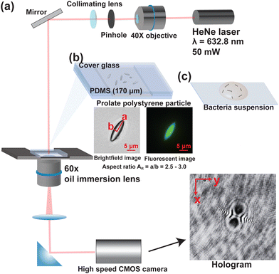 |
| | Fig. 2 (a) Holography experimental setup. We use a helium–neon laser (λ = 632.8 nm) with 50 mW power as the light source. The holograms are visualized under an inverted microscope with a 60× oil immersion lens and captured using a CMOS high speed camera. (b) The fluorescent, prolate PS particles are embedded in a PDMS gel inside a 170 μm thick glass chamber. (c) For visualizing the E. coli cell sample, we place 500 μL of the suspension as prepared in Section 2.2 on a microscopy cover slip and follow the same imaging procedure to retrieve the video footage of the cell motion. We enhanced the hologram contrast for better visibility of the diffraction patterns. | |
2.2 Preparation of E. coli samples
Motile Escherichia coli (HCB-437) was cultured as described in Ahmadzadegan et al. (2019)42 and re-suspended in a motility medium (10−2 M potassium phosphate, pH 7.0, 10−4 M EDTA). 500 μL of the solution is then placed on microscopy cover glass and imaged.
2.3 In-line holographic microscopy setup
The digital inline holography setup was modified from the setup described in Molaei et al. (2014).43 We used a HeNe Laser with a wavelength of 632.8 nm (Melles Griot). A 60× Nikon objective lens focuses the laser beam onto a 50 μm pinhole (Thorlabs) and a convex lens with a 50 mm focal length is placed at a distance of 50 mm from the pinhole to create a collimated beam of light that is directed toward the sample on a microscope.
2.4 Confocal microscopy setup
A spinning disk confocal module (Crest Optics) is attached to a Nikon Ti microscope to simultaneously capture images from both the holography setup as well as benchmark the location and orientation from a confocal z-slice scan.
3 Hologram reconstruction and particle position/orientation detection
The system and coordinate definition is summarized in Fig. 3. Here we adopt a dimensionless group Fresnel number Fr to characterize the optical regime:| |  | (1) |
where a is the characteristic size of the object, λ is the wavelength of the illumination beam, and L is the observation distance from the particle center of mass. Here we chose the semi-major axis length of the particle as the characteristic size. In general, Fr ≥ 1 denotes the near field regime and Fr < 1 represents the far field regime.
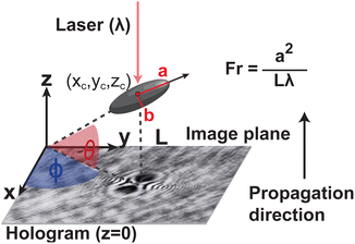 |
| | Fig. 3 Schematic of the coordinate system. The image plane is in the x–y plane and the optical axis is along the z-axis. The wavelength of the laser is λ. The hologram plane is defined to be in the plane of z = 0. The particle's center of mass is at (xc, yc, zc) and the semi-major and minor axes lengths are a and b, respectively. The particle aspect ratio is AR = a/b. The particle orientation is defined based on the particle's axis of symmetry. The azimuth angle ϕ is the angle between the positive x-axis and the projection of the particle's axis of symmetry on the x–y plane. The altitude angle θ is the angle between the particle's axis of symmetry and the x–y plane. The holograms are propagated in the positive z direction. We use Fresnel number Fr = a2/Lλ to characterize the optical regime. We enhanced the hologram contrast for better visibility of the diffraction patterns. | |
The captured holograms are first processed with background subtraction to improve the image quality. The processed hologram is then numerically propagated along the optical axis direction using an angular spectrum method to retrieve images at different depth positions.22 We then apply image moment techniques to detect the particle center of mass and orientation. We will introduce the image processing steps in the following sections.
3.1 Hologram propagation
The hologram U(x, y; z = 0) is numerically propagated along the optical axis direction to retrieve the image at different z positions (Fig. 4c). The propagated image U(x, y; z = zi) at plane z = zi is calculated using the following equation:22| | 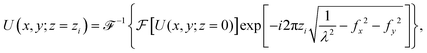 | (2) |
where fx, fy represent the spatial frequency in the x, y direction respectively in the frequency space, λ is the laser wavelength, and  ,
,  are the forward and inverse 2D fast Fourier transform (2D-FFT/2D-iFFT), respectively. The angular spectrum method models the propagation of light waves as a superposition of infinite number of planar waves. This method is in general valid in the near-field regime (Fr ≥ 1).22
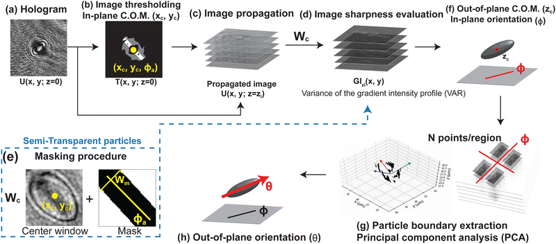 |
| | Fig. 4 Reconstruction flow chart for identifying the particle center of mass (xc, yc, zc) and orientation (ϕ, θ). (a) Original hologram. (b) The hologram is thresholded to determine the in-plane center of mass (xc, yc) and the approximate in-plane angle ϕa. (c) The original hologram is numerically propagated to reconstruct images at different z positions. (d) For each z layer, the image sharpness is evaluated in a box of width Wc centered around (xc, yc). This procedure allows one to identify the out-of-plane center of mass zc. (e) For semi-transparent particles, a mask of width Wm along the particle's major axis is added to the sharpness evaluation step to improve the detection accuracy for zc. (f) The in-plane orientation angle ϕ is determined by calculating the image moments of the superimposed gradient intensity profile around zc. (g and h) We finally extract the particle boundary and perform PCA to determine the out-of-plane tilt angle θ. We enhanced the hologram contrast in this figure for better visibility of the diffraction patterns. | |
3.2 Particle center of mass and orientation detection
3.2.1 Center of mass detection.
For an image I(x, y), we define the a-th moment in the x direction and b-th moment in the y direction mab by the following equation:| | 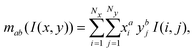 | (3) |
where Nx, Ny represents the number of pixels of the image in the x and y direction, respectively.
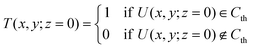
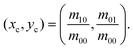
To determine the center of mass in the x–y plane, we apply thresholding to the processed hologram U(x, y; z = 0) (eqn (4)) to get the threshold image T(x, y; z = 0). For the pixels in U(x, y; z = 0) that meet the threshold criteria Cth, we assign the corresponding pixel value in T(x, y; z = 0) to be 1 (positive pixels) and others to be 0 (negative pixels). We then estimate the in-plane center of mass xc, yc by averaging the x and y position of the positive pixels in the threshold image viaeqn (5) (Fig. 4b):44,45
| |  | (4) |
| |  | (5) |
We next determine the out-of-plane center of mass
zc of the particle by image sharpness. In each propagated image
U(
x,
y;
z =
zi), we examine a window around (
xc,
yc) of width
Wc (
i.e. |
x −
xc| ≤
Wc/2, |
y −
yc| ≤
Wc/2) that covers the entire particle. For the
AR = 3 prolate particles used in this work, we set
Wc = 2.5
a ≈ 15 μm, or 2.5 times of the average particle semi-major axis length to ensure the coverage of the target particle. At each
zi, we convolve the Sobel filter on the center window image in both the
x and
y directions to calculate the horizontal and vertical image gradient profiles
Gx,zi,
Gy,zi of the image at each propagation layer (
eqn (6) and (7)).
7,32| | 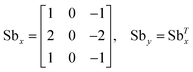 | (6) |
| | | Gx,zi = U(x, y; z = zi) * Sbx, Gy,zi = U(x, y; z = zi) * Sby for |x − xc| ≤ Wc/2, |y − yc| ≤ Wc/2 | (7) |
where * represents a 2-D convolution operation. We next define the gradient intensity profile GI
zi(
x,
y) at
z =
zi to be the
l2 norm of the horizontal and vertical gradient profile at the corresponding position (
eqn (8)). For each layer
z =
zi, we calculate the variance of the gradient intensity profile (VAR) as a metric for the image contrast and sharpness.
37,46| | 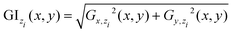 | (8) |
| |  | (9) |
where
μzi and VAR
zi are the mean value and the variance of the gradient intensity profile at
z =
zi, respectively. A sharp pattern (abrupt change in pixel value) will generate strong gradient values in the nearby pixels in the gradient profile and lead to a high variance value. For an optically opaque particle (
e.g. coal particle, metallic nano-particles), sharp patterns appear only when the target object is in focus.
27,32 We can therefore pick the
z layer that gives the highest variance value to be the particle center of mass in the
z direction, or
zc = argmax(VAR
zi). For a semi-transparent particle (
e.g. ellipsoidal polystyrene particle), however, the particle can act as a lens and generate sharp patterns at
z positions near the focal point of the lens.
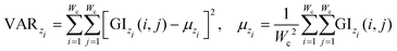
1,2 For this type of particle, we often observe a wide peak in the image gradient variance profile along the
z direction that spans from the focal point to the particle center of mass. The black curve in
Fig. 5a shows the VAR intensity with respect to the
z position for a semi-transparent prolate polystyrene particle. In this case, the diffraction patterns that appear around the focal point (
Fig. 5b) can also give a strong response in VAR. Picking the
z that gives the strongest VAR response may not guarantee the correct
zc position of the particle. To handle this issue, we additionally impose a mask during the image variance calculation process to help us better identify the location of the particle center of mass.
 |
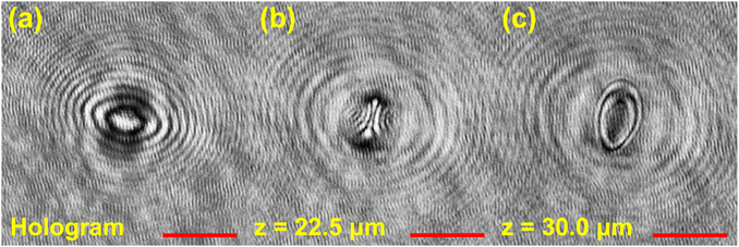
| | Fig. 5 (a) Variance of the gradient intensity profile VAR at different z layers from one of the sample particles. The center of mass of the particle is identified to be zc = 30.00 μm based on confocal measurements. The black and red lines represent the profile with and without the center mask, respectively. The inset illustrates the center mask. The mask covers the pixels along the particle's major axis direction with width Wm. The gradient intensity values inside the mask are neglected when calculating VAR. In the plot, the variance profiles are normalized by the max variance of the individual profiles. The center box width for calculating VAR is Wc = 2.5a. (b) Reconstructed images of the propagated holograms at different z locations. (c-1) The horizontal and vertical gradient profiles Gx and Gy at z = 30.00 μm. (c-2) Total gradient intensity profile (GI), which is the l2 norm of Gx and Gy (eqn (8)). The variance of GI (VAR) is used as the metric to quantify image sharpness and hence identify zc. (c-3) The superimposed gradient intensity profiles GIS in |z − zc| ≤ 2.5 μm. The scale bar is 5 μm. We enhanced the hologram contrast in this figure for better visibility of the diffraction patterns. For figure (b and c), no mask is applied to better visualize the lens effect pattern or particle contour. | |
For the original hologram U(x, y; z = 0), we apply thresholding and eqn (11) (described in the next subsection) to calculate the approximated in-plane orientation ϕa of the particle. A mask along the direction of ϕa with width Wm is applied to the center window |x − xc| ≤ Wc/2, |y − yc| ≤ Wc/2 during the image sharpness evaluation step (Fig. 4d and 5c). The mask covers the center region of the particle and the diffraction patterns appearing within the mask is neglected during the image sharpness evaluation step. The red line in Fig. 5a shows the VAR profile along the z direction after applying a mask with Wm = 1.6b. The application of the mask divides the bulk peak into two major regimes. The first regime covers the z layers that contain the diffraction patterns seen before the particle comes into focus, and the second peak appears at the z layer that the particle is in focus (Fig. 5b).1,2,32 We will then pick the z location of the second major peak as the location of the particle z center of mass for this kind of of semi-transparent particles. The rule of thumb for picking the width of the center mask is that Wm should be less than twice the particle minor axis length, or Wm < 2b. For this work, we will use a mask with a width that is 80% of this criterion, or Wm = 1.6b.
4 Results
In Sections 4.1–4.4, we perform tests to study the effect of different process parameters on the reconstruction results, and verify the accuracy of the proposed methodology. For these tests we use stagnant, fluorescent polystyrene particles prepared in Section 2.1 as our model particles. We embed these particles in a PDMS gel and randomly select 12 particles from the sample and record their holograms at L = 30, 40, 50 and 75 μm from the particle center of mass. For an AR = 3 prolate particle with a = 6.24 μm, the Fresnel number is 2.05, 1.54, 1.23, and 0.82, respectively. We compare the holography results to measurements from confocal microscopy, which we regard as the “ground truth”. In Section 4.5, we illustrate how standard line fitting methods in the holography literature do not accurately capture particle orientation for semi-transparent particles with O(1) aspect ratio. This phenomenon arises from the lens effect, and the masking procedure introduced in this paper allows one to overcome this issue to correctly identify particle orientation. Lastly, in Section 4.6 we demonstrate the ability of this method to analyze the 3-D motion of E. coli cells in an aqueous medium from holographic video footage.
4.1 Effect of thresholding criteria Cth on mask generation
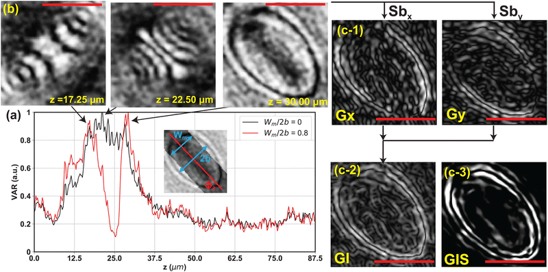
An appropriate choice of thresholding criteria can provide us with a good estimation of the in-plane orientation ϕa and thus generate a mask that can help us more precisely locate the particle boundary. For the 12 sample particles, we use the holograms taken at L = 30 μm for the test. For each raw hologram, we apply different threshold values Cth and use the pixels with values lower than Cth to calculate the approximate in-plane angle ϕa. Fig. 6 reports the average absolute difference between the approximate and confocal in-plane angle |ϕa − ϕcf| versus the percentage of total number of pixels used for the ϕa calculation. We see the error is minimum for the in-plane when the threshold value covers the first 2 to 3% of the lowest intensity pixels. The error becomes significant when too few or many pixels are used in the calculation. The detected ϕa approaches 45° when all the pixels are used in the calculation. We therefore choose Cth that covers no more than the first 2–5% lowest intensity pixels for ϕa calculation and mask generation. Here we take the 2nd to 5th percentile pixel value from the histogram of the hologram as the threshold value.
 |
| | Fig. 6 (a) The average absolute detection error between the approximate and confocal detected in-plane angle |ϕa − ϕcf| for the 12 sample particles using different thresholding criteria for the lowest intensity pixels. (b) The average absolute error between the approximate and confocal detected in-plane angle |ϕa − ϕcf| for the 12 sample particles at various observation distances L = 30, 40, 50, and 75 μm. We use Cth that covers the first 2–5% lowest intensity pixels for thresholding. (c) The average absolute detection error between the holography and confocal detected out-of-plane angle |θ − θcf| for the 12 sample particles using various numbers of points N in the principal component analysis. The holograms used in this test are taken at L = 30 μm. The process parameters for these tests are Wc = 2.5a and Wm = 1.6b. The error bars in these plots represent 1 standard deviation of the angle error for the 12 model particles. | |
4.2 Effect of observation distance on mask generation
We next discuss how the observation distance L affects the detection of approximate in-plane angle ϕa as well as the mask generation results. For semi-transparent particles, the generation of a mask relies on a good approximation of the particle in-plane angle from the raw hologram. For the 12 sample particles we use holograms taken at L = 30, 40, 50, and 75 μm and use Cth that extracts the first 2–5% lowest intensity pixels for thresholding. We compare the resulting ϕa to the confocal experiment measurement ϕcf to quantify the quality of the detection. We report the average absolute angle difference |ϕa − ϕcf| for the 12 sample particles at different observation distance L in Fig. 6b. We see that for the aspect ratio 3 prolate particle used in the test, the average error is about 4 degrees at L = 30, 40 μm. As we move farther away from the particle towards the far-field regime, the diffraction pattern in the raw hologram spreads wider along the minor axis direction and the estimated in-plane angle ϕa deviates farther from the correct major axis direction. At a far enough observation distance from the particle center of mass (e.g. L = 75 μm in Fig. 7a), our procedure incorrectly captures the minor axis direction of the particle as ϕa, which introduces a 90 degree error from the particle major axis. For the 12 sample particles used in this test, we see this phenomenon for 4 particles at z = 50 μm and 2 particles at z = 75 μm.
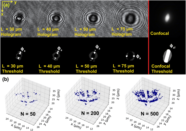 |
| | Fig. 7 (a) Holograms and thresholded images of a sample particle taken at L = 30, 40, 50, and 75 μm from the particle center of mass. The confocal image of the particle is shown on the right for comparison. We use Cth that covers 2 to 5% lowest intensity pixels for thresholding. We calculate the approximate in-plane angle ϕa using eqn (11) and compare against the “ground-truth” value ϕcf from the confocal image. All angles are visualized as white lines in the thresholded images. We enhanced the hologram contrast for better visibility of the patterns. (b) The image of the extracted particle contour from principal component analysis using N = 50, 200, and 500. The particle center of mass is located at zc = 30 μm. | |
4.3 Effect of PCA parameter N on the detection results
We next discuss how the number of points used in the principal component analysis affects the detection of the out-of-plane θ angle (Fig. 4f). For the 12 sample particles, we use the holograms taken at L = 30 μm and measure their θ angle using N = 50, 100, 200, 300, 400, and 500 for each of the four regions (200, 400, 800, 1200, 1600, and 2000 total number of pixels, respectively). The reconstructed θ are compared to the confocal reconstruction θcf to calculate the reconstruction error. The plot of the average absolute error |θ − θcf| with respect to N for the 12 sample particles is shown in Fig. 6c. We see that the averaged absolute error in θ angle for different N is within 3 degrees, with N = 200 giving the smallest average error. When an inadequate number of pixels (N < 200) is used in the analysis, the pixels cannot properly capture the contour of the particle, and therefore gives a larger deviation from the correct value. On the other hand, as more pixels (N > 200) are used in the PCA, the data set can contain excessive noise in addition to the particle contour location, and the PCA tends to give incorrect detection results. Fig. 7b shows an example of the extracted particle contour using a different number of points. We thus choose N = 200 for the PS prolate particles used in this work.
4.4 Reconstruction result verification
We use the same set of 12 particles to verify the reconstruction accuracy of our method. The captured holograms are reconstructed using the proposed method to retrieve the particle's position and orientation (xc, yc, zc, ϕ, θ). The results are compared to the confocal reconstruction results (xc,cf, yc,cf, zc,cf, ϕcf, θcf) to calculate the error. We specifically report the results for zc, ϕ and θ. Here we pick the process parameters to be the following: threshold value Cth = 3rd percentile pixel intensity, center window width Wc = 2.5a, center mask width Wm = 1.6b, and the number of points used in principal component analysis in each section N = 200. Fig. 8a shows the error in zc normalized by the average particle dimension (a + b). The data indicates that the average error in zc is in general less than 25% of the average particle thickness (≈ 2–3 μm) and the error grows as the observation distance increases. The average error in ϕ is about 2 to 4 degrees and the error shows weak dependence on the observation distance L. Finally the average error in θ falls between 2 to 5 degrees, and the variation in the error increases with the observation distance L.
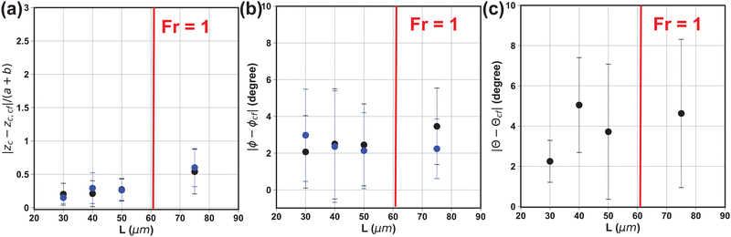 |
| | Fig. 8 Plots of the (a) normalized, absolute average error of zc, (b) absolute average error of ϕ angle, and (c) absolute average error of θ angle with respect to the observation distance L from the particle center of mass for the 12 sample particles. The error is calculated by the difference between the confocal reconstruction (zc,cf, ϕcf, θcf) and holographic reconstruction (zc, ϕ, θ). The error bar represents one standard deviation of the error from the 12 sample particles at each L. The reconstruction error using the method proposed by Byeon et al. (2016)a, b1,2 is shown in blue color for comparison. The vertical red line located at L = 61.5 μm marks the location where Fr = 1 using a = 6.24 μm, λ = 0.6328 μm. The error in zc is normalized by the average particle size (a + b). | |
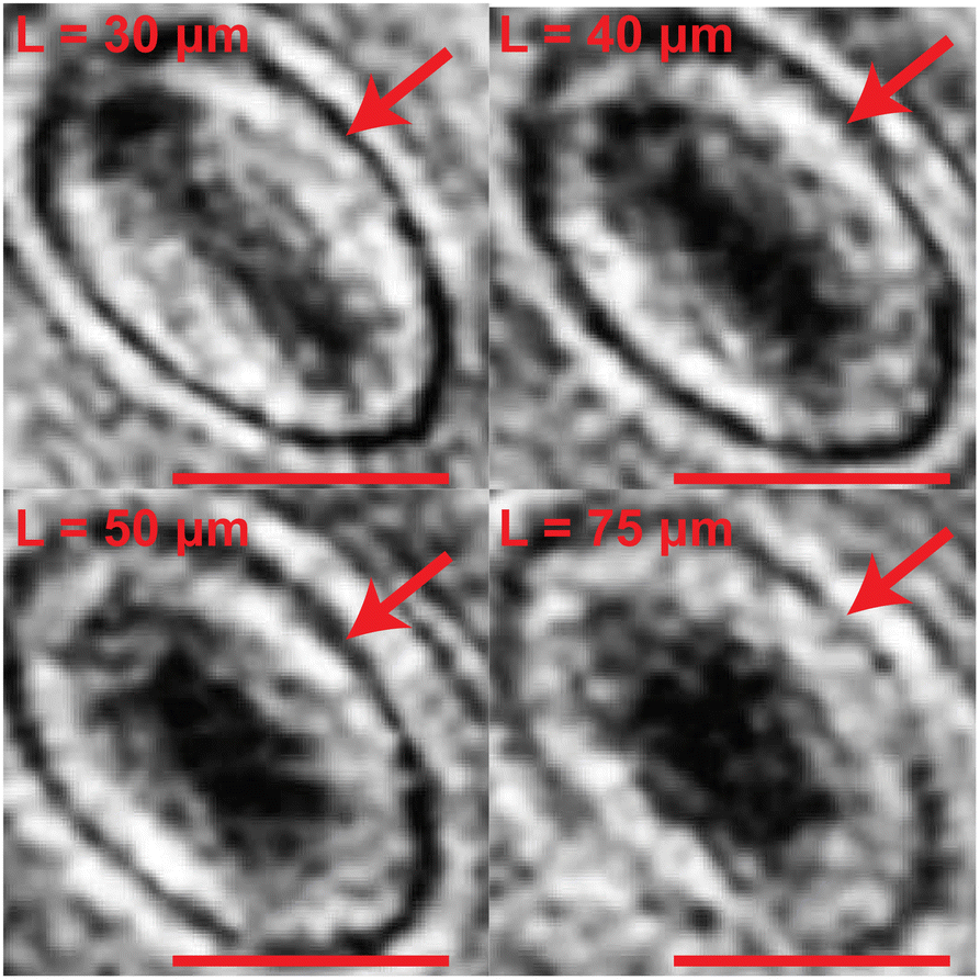
The dependence of zc and θ error on the observation distance L arises from the nature of the reconstruction method and the PDMS gel. As the observation distance increases (Fr decreases into the far-field regime Fr < 1), the error in zc and θ grows due to the limitation of the angular spectrum method, as well as the attenuation of the light through a thicker layer of PDMS gel. Fig. 9 shows the image of the same particle reconstructed from the hologram at different observation distances. We find that the local PDMS gel structure introduces additional noise into the holograms that cannot be completely removed in the background subtraction process. This noise is present in all holograms and can affect the reconstruction quality.
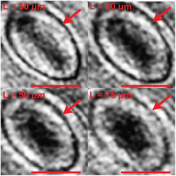 |
| | Fig. 9 The reconstructed image at z = zc for an identical, semi-transparent polystyrene particle from various observation distances L = 30, 40, 50, and 75 μm with Fr = 2.05, 1.54, 1.23, and 0.82, respectively. The reconstructed image shows a less well-defined particle boundary (red arrow) as the observation distance L increases. This is due to the attenuation of light through a thicker layer of PDMS gel as well as the limitation of the angular spectrum method. The scale bar is 5 μm. We enhanced the image contrast for better visibility of the particle contour. | |
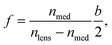
We finally compare our reconstruction method to the method proposed by Byeon et al.1,2 In their work, the holograms are propagated using the identical angular spectrum method to reconstruct the image at different z positions. To determine the particle center of mass in the z direction, the method assumes the particle to be a perfect spheroid and treats the particle as a convex lens. Once the position of the focal point (i.e., the location where the light beam crosses) and the focal length of the lens is known, one can extend from the focal point by the distance of focal length to find zc of the particle. For a spheroidal lens with semi-minor axis length b, the focal length f of the lens can be calculated using the following eqn (13):2
| |  | (13) |
where
nlens and
nmed represent the refractive index of the lens material and the surrounding medium, respectively. In our system, we have
nlens =
nPS = 1.59 and
nmed =
nPDMS = 1.42. The
ϕ angle of the particle can be determined by thresholding the image near the focal point and estimating the orientation of the bright stripe. As for determining the
θ angle of the particle, however, the method proposed by Byeon
et al.2 relies on a rather ambiguously defined detection process, and a direct quantitative comparison will be difficult. We therefore only compare the detection result of
zc and
ϕ between the two methods.
The detection error using the method by Byeon et al.1,2 is shown in Fig. 8a and b with blue color. In general, the method by Byeon et al.1,2 gives a similar amount of error in zc in comparison to the method proposed in this work. The error in zc also similarly grows with increasing L due to the limited applicability of the angular spectrum method in the near-field regime (Fr ≤ 1). The method shows similar accuracy in detecting the ϕ angle compared to our method. We note that the method by Byeon et al.1,2 uses the exact particle dimensions for calculating the particle focal distance and the correct zc location. In our work, we use the average major/minor axis length and aspect ratio acquired by bulk measurements to help us determine the process parameters and identify the appropriate detection region. This design can achieve comparable detection accuracy in zc and ϕ as Byeon's method. Our method in addition provides a more clearly defined framework for identifying the particle's 3-D tilt angle θ.
4.5 Comparison to line fitting reconstruction methods
Line segment fitting methods are commonly used for detecting the 3-D orientation of slender particles (AR ≫ 1) such as metal nano-rods, malaria cells and E. coli cells.27,33,34,36,43 For the semi-transparent ellipsoidal particle with the O(1) aspect ratio used in this work, line fitting methods may not give reasonable detection results since the particle boundary pixels do not form a straight line. The patterns from the lens effect may also significantly affect the detection result. To elaborate this point, we examine holograms of an AR = 3 prolate polystyrene particle taken at L = 30 μm as an example. We follow the procedures in Section 3.2.2 to extract the gradient intensity profile around its center of mass at zc = 30 μm and record the location of pixels where an abrupt change in pixel value is observed. We apply PCA to the recorded data without masking and extract the eigenvector of the first principal component as the direction of the best-fit line. The out-of-plane orientation of the best fit line is compared to the detected orientation by confocal microscopy. The top and bottom row of Fig. 10 shows the location of the particle boundary pixels when a mask is not applied and applied, respectively. The green and red arrows in the figure show the particle orientation obtained from the confocal microscopy experiments and the first principal component of PCA, respectively. The confocal result gives θ = 18.3°. When no mask is applied, the patterns from the lens effect significantly distort the detection results and yield an incorrect estimation of the particle orientation (θ = 63.4°). When a mask is applied to cover the sharp patterns from the lens effect, the remaining pixels can better capture the location of the boundary pixels and gives a more accurate detection of the particle orientation (θ = 17.1°).
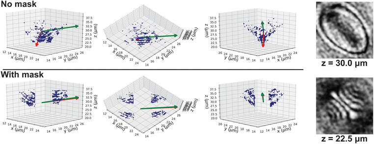 |
| | Fig. 10 Visualization of the line fitting results with and without a masking procedure. The extracted strong variance intensity pixels are shown as blue dots. The red arrow is the direction of the first principal component of the extracted pixels and the green arrow is the ground truth orientation from confocal microscopy (θ = 18.3°). If no mask is applied, the lens effect shown in the z = 22.5 μm picture distorts the pixel pattern so much that the orientation detection is incorrect (θ = 63.4°). When a mask is applied, the detected orientation is θ = 17.1°. The particle center of mass for this particle is located at zc = 30 μm and the sharp patterns from the lens effect appears around the focal point of the particle z = 22.5 μm. | |
4.6 Motion of an E. coli cell in aqueous medium
We finally demonstrate the ability of the method to analyze the 3-D motion of E. coli cells from a holographic video footage. The E. coli samples are prepared following the steps in Section 2.2. The average major axis length is about 5 μm and the aspect ratio is 5. The holographic video is taken using the same experimental setup as described in Section 2 at a rate of 24 fps, and the length of the footage is 14 seconds. Fig. 11a shows a snapshot of the video footage. The full video footage can be found in the ESI.† We specifically reconstruct the position and orientation trajectories with respect to time for the four E. coli cells in the red boxes of Fig. 11a. Due to the opacity of the bacteria cells, we will not apply the center mask in the analysis (Wm = 0). To cope with the slender shape of the cells, we use Wc = 0.6a and N = 25 for the reconstruction. Fig. 11b shows the superimposed particle trajectory in the x–y plane. The inset image shows one of the reconstructed frames. Fig. 11c shows the 3-D visualization of each cell's position and orientation trajectory, where the dots and arrows represent the center of mass and orientation of the bacteria cell. The blue and red dots mark the location of the cell at the beginning and at the end of the footage, respectively.
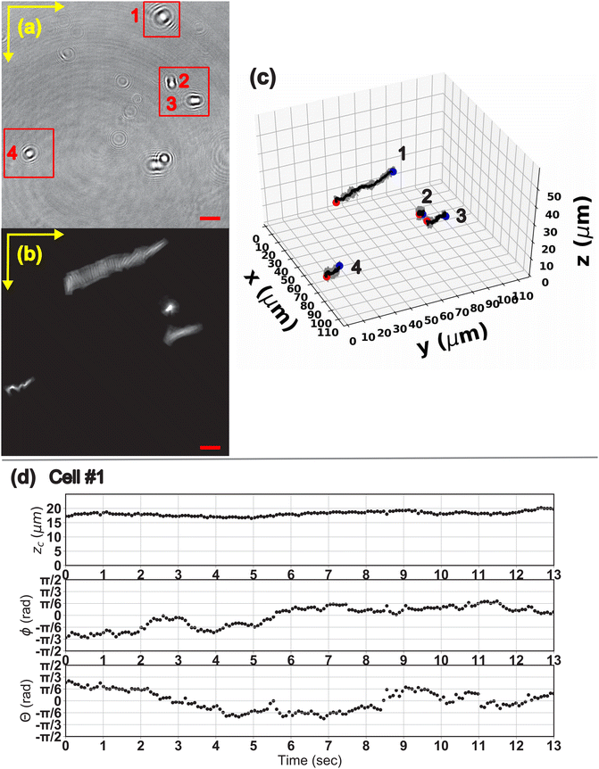 |
| | Fig. 11 (a) A snapshot of the holographic video footage of the E. coli cell moving in a motility medium. We specifically follow the 4 bacterial cells in the red boxes. (b) The superimposed cell trajectories in the x–y plane. (c) The 3-D visualization of the cell trajectories. The dots and arrows represent the cell center of mass and orientation. The blue and red dots mark the starting and ending location of the cell, respectively. (d) The zc, θ and ϕ trajectory of cell #1 with respect to the video time. The scale bar for all the figures is 10 μm. The video footage of all cells is found in the ESI.† The detailed trajectories for cells #2–4 can be found in the ESI,† Fig. S1–S3. | |
The plots of the zc, ϕ and θ trajectories of cell #1 with respect to the video time is shown in Fig. 11d. The trajectories of the other 3 cells are available in the ESI,† Fig. S1–S3. The E. coli cell migrates over a distance of 52 μm in the 14 second time interval, and the zc of the cell fluctuates between 17 to 20 μm above the hologram plane. The orientation data shows that the cell first migrates along its major axis direction and gradually turns into a log-rolling motion with the θ angle seesawing around θ = 0. Finally we note that the method is also able to capture the motion of a bacteria cell whose orientation is nearly perpendicular to the image plane (cell #4). The results in this section demonstrate the ability of the method to resolve the motion of a dynamic microparticle in 3-D space. The results also demonstrate that the method is applicable to both semi-transparent and opaque particles.
5 Conclusions
In this work, we developed a methodology that allows us to retrieve the 3-D information of a non-spherical microparticle via in-line digital holography. We applied the angular spectrum method to reconstruct an image at different z positions, and used the gradient intensity information to locate the out-of-plane particle center of mass zc and the in-plane orientation ϕ. Principal component analysis is applied to the gradient intensity profiles to extract the out-of-plane θ angle of the particle. For semi-transparent particles with O(1) aspect ratio, we utilized the image moment information to generate masks during the image sharpness evaluation process. The mask covers the diffraction patterns from the lens effect and helps us better locate the correct particle center of mass location. The process parameters such as Wc, Wm are tailored based on the average dimension of the particle. We verified the proposed method by comparing with confocal microscopy measurements. The detection error in zc falls within 25% of the average particle thickness (a + b), and the average errors in ϕ and θ are about 2° and 4°, respectively. The reconstruction error in general increases with the longer observation distance L (smaller Fr) due to the limitation on the angular spectrum method as well as the attenuation of light signal through a thicker layer of PDMS gel. The reconstruction quality is also sensitive to the noise caused by the local PDMS structure. We also verified that our method shows similar detection accuracy in zc and ϕ to the method proposed by Byeon et al.1,2 This method also provides a more clearly defined framework to identify the out-of-plane tilt angle. We finally demonstrated the ability of the method to process holographic video footage and quantitatively analyze the 3-D motion of opaque E. coli cells. This method provides adequate accuracy in zc for applications where errors on the order of particle size are acceptable – e.g., tracking micron size objects in macroscopic flows. To gain a better resolution in the depth direction, one can possibly utilize additional laser beams at a tilted angle to gain additional information in the depth direction.19,47 For particles with a similar length scale to the light wavelength, methods that tackle the reverse problem via hologram simulation and statistical inference28,29,31 can provide better accuracy.
Conflicts of interest
The authors report no conflict of interest.
Acknowledgements
We thank Mr Nick Humphrey for the help with the design and fabrication of the film stretching device. Cheng-Wei Tai and Vivek Narsimhan acknowledge the financial support from the American Chemical Society Petroleum Research Fund (ACS PRF 61266-DNI9). Arezoo M. Ardekani acknowledges NSF grant CBET-2141404.
Notes and references
- H. Byeon, T. Go and S. J. Lee, Appl. Opt., 2016, 54, 2106–2112 CrossRef.
- H. Byeon, T. Go and S. J. Lee, Opt. Express, 2016, 24, 598–610 CrossRef.
- E. K. Sackmann, A. L. Fulton and D. J. Beebe, Nature, 2014, 507, 181–189 CrossRef CAS PubMed.
- F. Del Giudice, M. Tassieri, C. Oelschlaeger and A. Q. Shen, Macromolecules, 2017, 50, 2951–2963 CrossRef CAS.
- N. Shokeen and A. Mukhopadhyay, Colloid Polym. Sci., 2021, 299, 1595–1603 CrossRef CAS.
- G. W. Graham and W. A. M. Nimmo Smith, Limnol. Oceanogr.: Methods, 2010, 8, 1–15 CrossRef.
- L. Yao, J. Chen, P. Sojka, X. Wu and K. Cen, Opt. Lett., 2018, 43, 1283 CrossRef.
- L. A. Philips, D. B. Ruffner, F. C. Cheong, J. M. Blusewicz, P. Kasimbeg, B. Waisi, J. R. McCutcheon and D. G. Grier, Water Res., 2017, 122, 431–439 CrossRef CAS.
- C. Schweizer, S. Prasad, A. Saini, C. V. Mashuga and W. D. Kulatilaka, Powder Technol., 2020, 376, 612–621 CrossRef CAS.
- G. Li and A. M. Ardekani, Phys. Rev. Lett., 2016, 117, 1–5 Search PubMed.
- S. Bianchi, F. Saglimbeni and R. Di Leonardo, Phys. Rev. X, 2017, 7, 1–9 Search PubMed.
- A. Ahmadzadegan, S. Wang, P. P. Vlachos and A. M. Ardekani, Phys. Rev. E, 2019, 100, 62605 CrossRef.
- R. V. More and A. M. Ardekani, Phys. Rev. E, 2021, 103, 1–13 Search PubMed.
- T. Garting and A. Stradner, Small, 2018, 14, 1801548 CrossRef.
- Ó. Guadayol, T. Mendonca, M. S.-N. Amand, J. Wright, M. Tassieri and S. Humphries, Proc. Natl. Acad. Sci. U. S. A., 2020, 118, 2011389118 CrossRef.
- J. P. Binagia and E. S. Shaqfeh, Phys. Rev. Fluids, 2021, 6, 1–18 Search PubMed.
- D. R. Guildenbecher, M. A. Cooper, W. Gill, H. L. Stauffacher, M. S. Oliver and T. W. Grasser, Opt. Lett., 2014, 39, 5126 CrossRef.
- K.-B. Im, S. Han, H. Park, D. Kim and B.-M. Kim, Opt. Express, 2005, 13, 5151–5156 CrossRef.
- F. Saglimbeni, S. Bianchi, A. Lepore and R. Di Leonardo, Opt. Express, 2014, 22, 13710 CrossRef CAS.
- L. van der Graaff, G. J. L. H. van Leenders, F. Boyaval and S. Stallinga, Biomed. Opt. Express, 2019, 10, 6313 CrossRef.
- D. Gabor, Nature, 1948, 161, 777–778 CrossRef CAS PubMed.
-
J. W. Goodman, Introduction to Fourier Optics, McGraw-Hill Companies, Inc., 4th edn, 2017 Search PubMed.
- J. Katz and J. Sheng, Annu. Rev. Fluid Mech., 2010, 42, 531–555 CrossRef.
- P. Memmolo, L. Miccio, M. Paturzo, G. D. Caprio, G. Coppola, P. A. Netti and P. Ferraro, Adv. Opt. Photonics, 2015, 7, 713 CrossRef.
- L. Lorenz, Det Kongelige Danske Videnskabernes Selskabs Skrifter, 1890, 6, 1–62 Search PubMed.
- G. Mie, Ann. Phys., 1908, 330, 377–445 CrossRef.
- F. C. Cheong, B. J. Krishnatreya and D. G. Grier, Opt. Express, 2010, 18, 13563 CrossRef PubMed.
- T. G. Dimiduk and V. N. Manoharan, Opt. Express, 2016, 24, 24045 CrossRef CAS PubMed.
- M. A. Yurkin and A. G. Hoekstra, J. Quant. Spectrosc. Radiat. Transfer, 2011, 112, 2234–2247 CrossRef CAS.
- A. Wang, T. G. Dimiduk, J. Fung, S. Razavi, I. Kretzschmar, K. Chaudhary and V. N. Manoharan, J. Quant. Spectrosc. Radiat. Transfer, 2014, 146, 499–509 CrossRef CAS.
- R. Alexander, B. Leahy and V. N. Manoharan, J. Appl. Phys., 2020, 128, 060902 CrossRef CAS.
- Y. Wu, X. Wu, J. Yang, Z. Wang, X. Gao, B. Zhou, L. Chen, K. Qiu, G. Gérard and K. Cen, Appl. Opt., 2014, 53, 556 CrossRef.
- M. Kmpkes, E. Darakis, T. Khanam, A. Rajendran, V. Kariwala, M. Mazzotti, T. J. Naughton and A. K. Asundi, Opt. Express, 2009, 17, 2938 CrossRef PubMed.
- F. C. Cheong and D. G. Grier, Opt. Express, 2010, 18, 6555 CrossRef CAS.
- T. Khanam, M. Nurur Rahman, A. Rajendran, V. Kariwala and A. K. Asundi, Chem. Eng. Sci., 2011, 66, 2699–2706 CrossRef CAS.
- L. G. Wilson, L. M. Carter and S. E. Reece, Proc. Natl. Acad. Sci. U. S. A., 2013, 110, 18769–18774 CrossRef CAS.
- F. C. Groen, I. T. Young and G. Ligthart, Cytometry, 1985, 6, 81–91 CrossRef CAS.
- P. Langehanenberg, G. von Bally and B. Kemper, 3D Res., 2011, 2, 1–11 Search PubMed.
- K. W. Seo, H. J. Byeon and S. J. Lee, Opt. Lett., 2014, 39, 3915 CrossRef PubMed.
- C. Ho, A. Keller, J. A. Odell and R. Ottewill, Colloid Polym. Sci., 1993, 271, 469–479 CrossRef CAS.
- J. A. Champion, Y. K. Katare and S. Mitragotri, Proc. Natl. Acad. Sci. U. S. A., 2007, 104, 11901–11904 CrossRef CAS.
- A. Ahmadzadegan, S. Wang, P. P. Vlachos and A. M. Ardekani, Phys. Rev. E, 2019, 100, 062605 CrossRef.
- M. Molaei, M. Barry, R. Stocker and J. Sheng, Phys. Rev. Lett., 2014, 113, 068103 CrossRef.
- M. R. Teague, J. Opt. Soc. Am., 1980, 70, 920–930 CrossRef.
-
M. Pawlak and X. Liao, Proceedings - International Conference on Pattern Recognition, 1992, vol. 3, pp. 549–552 Search PubMed.
- J. Gillespie and R. A. King, Pattern Recognit. Lett., 1989, 9, 19–25 CrossRef.
- S. Bianchi, F. Saglimbeni, G. Frangipane, D. Dell’Arciprete and R. Di Leonardo, Soft Matter, 2019, 15, 3397–3406 RSC.
|
| This journal is © The Royal Society of Chemistry 2023 |
Click here to see how this site uses Cookies. View our privacy policy here. 
 a,
Adib
Ahmadzadegan
a,
Adib
Ahmadzadegan


 ,
,  are the forward and inverse 2D fast Fourier transform (2D-FFT/2D-iFFT), respectively. The angular spectrum method models the propagation of light waves as a superposition of infinite number of planar waves. This method is in general valid in the near-field regime (Fr ≥ 1).22