 Open Access Article
A transparent iron-incorporated nickel hydroxide electrocatalyst for efficient water oxidation
Amira Y.
Ahmed
a,
Dattatray S.
Dhawale
 *b and
Tarek A.
Kandiel
 *cd
*cd
aDepartment of Chemistry, Faculty of Science, Sohag University, Sohag 82524, Egypt
bCSIRO Energy, Private Bag 10, Clayton South 3169, Victoria, Australia. E-mail: dattatray.dhawale@csiro.au
cDepartment of Chemistry, King Fahd University of Petroleum & Minerals (KFUPM), Dhahran 31261, Saudi Arabia. E-mail: tarek.kandiel@kfupm.edu.sa; kandiel@science.sohag.edu.eg
dInterdisciplinary Research Center for Hydrogen and Energy Storage (IRC-HES) at KFUPM, Dhahran 31261, Saudi Arabia
First published on 22nd May 2023
Abstract
Developing transparent electrocatalyst films for the oxygen evolution reaction (OER) is indispensable for fabricating a tandem photoelectrochemical device for solar hydrogen production. Herein, we developed a facile solution-based method for depositing highly transparent iron-incorporated nickel hydroxide oxygen evolution electrocatalysts on conductive glass substrates (FTO). The analysis of UV-Vis spectra and electrochemical results of the fabricated electrodes indicated that the incorporation of iron into the nickel hydroxide electrocatalysts greatly influences their transmittance and electrocatalytic activity toward the OER. It increases the conductivity and activates the Ni sites at lower overpotential via stabilizing the OER intermediates as supported by electrochemical impedance measurements. At the optimized iron content, the obtained iron-incorporated nickel hydroxide electrode (FeNi-10) has a nanoplatelet-like morphology, and it requires just 290 mV to generate 10 mA cm−2 in an alkaline aqueous medium (1.0 M NaOH) with excellent stability. In comparison, a pristine nickel hydroxide electrode requires 384 mV under the same conditions. The overpotential obtained is significantly lower than that of the benchmark RuO2 and IrO2 oxide OER electrocatalysts deposited on FTO substrates. The transmittance of the FeNi-10 electrode is comparable to that of the FTO glass. Achieving such cost-effective, highly active, and transparent iron-incorporated nickel hydroxide OER electrodes offers an opportunity to fabricate tandem photoelectrochemical devices for low-cost solar fuel production.
1. Introduction
To meet the world's future energy needs and reduce the emission of greenhouse gases, green hydrogen gas (H2) is proposed as an appropriate chemical fuel and storage medium for solar energy that is harvested using a PV-integrated water electrolysis system.1–4 It can be used to compensate for the intermittency of solar energy. In an artificial photosynthetic system, H2 could be produced from water by integrating hydrogen and oxygen evolution electrocatalysts with a photovoltaic system (e.g., silicon solar cell).5,6 To enhance the efficiency of such a system, active and cheap materials for solar energy capture and conversion should be developed.7 In parallel to this crucial step, the discovery of active and abundant electrocatalysts to accelerate the kinetics of the sluggish oxygen evolution reaction (OER) and catalyze the water reduction at low overpotentials is pressingly needed.8 In particular, the discovery of electrocatalysts for the OER is of great interest.9,10 The OER is a challenging reaction that involves a multi-electron transfer and elementary steps besides the requirement for the O–O bond formation.11,12 It is thus a slow reaction and requires a catalyst to accelerate the reaction process to a kinetically acceptable rate. The practical OER electrocatalyst should have the following features: low overpotential, high stability, cheap, abundant, and scalable. To date, no single electrocatalyst fulfills all these criteria. However, IrO2 and RuO2 are the most efficient OER catalysts and exhibit the lowest overpotentials so far, they are expensive, and their unsustainable supply limits their use in large-scale applications.13Recently, many investigations have been dedicated to emerging cheap and transition-metal-based monometallic, bimetallic, and multi-metallic OER electrocatalysts to replace IrO2 and RuO2. They include, for example, cobalt oxide,14,15 manganese oxide,16 iron oxyhydroxide,17 nickel (oxy)hydroxides,18–20 nickel fluoride (NiF2),21 iron-incorporated NiS/Ni(OH)2,22 FeNi hydroxide,23 CoNi hydroxysulfides,24 NiFeV-LDH,25 and (Co0.3Mn0.1Ni0.6)(OH)2,26 and they exhibit suitable activities towards water oxidation with significantly lowered fabrication costs. Among the transition metal electrocatalysts, nickel (oxy)hydroxides have shown great potential as efficient electrocatalysts for the OER due to the accessible current density of 10 mA cm−2 at a relatively small overpotential.27,28 The electrocatalytic activities of nickel-based electrocatalysts for the OER were found to be greatly dependent on the presence of iron.20,27,29–31 In fact, nickel is always found in combination with iron in nature. It was discovered, in Ni-based alkaline batteries, that the Fe impurities in the nickel hydroxide electrodes significantly reduce their performance by minimizing the OER overpotential.32,33 This finding inspired numerous scientists to study this phenomenon. They optimized the Fe content and fabricated various nickel and iron (NiFe) based electrocatalysts to reach a high rate for the OER at low overpotential. Trotochaud et al.34 have investigated this system in detail and detected an improvement in the Ni(OH)2/NiOOH conductivity by more than 30-fold upon co-precipitation with iron. Moreover, they hypothesized that iron displays a partial-charge transfer effect on nickel, comparable to that noticed on the surface of the noble-metal-based electrode. The Fe3+ participation in a nickel (oxy)hydroxide causes optimal adsorption energies for OER intermediates and enhances the Ni reducibility, thus improving the OER activity.27,35–37 A very low overpotential (i.e., 200 mV) was recently reported for the OER over hierarchically structured three-dimensional nickel–iron electrodes from the alkaline electrolyte.38 The high activity and the low overpotential were attributed to the significantly improved active surface area, mass transport, and electron transfer. This report highlights the importance of the fabrication of nanostructured OER catalysts. In fact, with the rising demand for renewable and clean energy, developing a facile solution-based route for synthesizing transparent films of nanostructured OER electrocatalysts becomes essential for fabricating tandem devices for photoelectrochemical water splitting. Sunlight absorption by the electrocatalysts needs to be avoided to allow light transmission through the large bandgap photoelectrode to activate the smaller bandgap one.39
Pristine and Fe-incorporated nickel (oxy)hydroxide electrocatalysts are commonly synthesized by the hydrothermal37 and electrochemical deposition (ECD) methods.38,40,41 In this work, a facile solution-based chemical bath deposition (CBD) method has been developed to fabricate transparent iron-incorporated nickel hydroxide films on FTO glass without using any binder. Compared to the commonly employed hydrothermal and ECD methods, the proposed synthetic method is more feasible for scale-up without losing film homogeneity. Moreover, it allows the preparation of scalable electrocatalyst films with low electrical resistance for the water-splitting cell since no binder is used.38 The electrocatalyst films were fabricated simply by vertically immersing the clean FTO glass substrates in a chemical bath that contains nickel acetate and hexamethylenetetramine at 90 °C. To incorporate iron into the nickel hydroxide films, iron chloride was added to the chemical bath at the desired amounts. The electrochemical measurements indicated that the iron-incorporated nickel hydroxide electrocatalyst deposited from a chemical bath that contains 10 at% Fe exhibited the highest electrocatalytic activity. The overpotential required to generate 10 mA cm−2 from an alkaline aqueous medium (1.0 M NaOH) was 290 mV. This overpotential is better than that reported for RuO2 and IrO2 benchmark OER electrocatalysts deposited on FTO in a comparable electrolyte (see Table 1). Moreover, the film is fully transparent and has potential application in photoelectrochemical tandem device fabrication.
| Sample ID | Fe/(Fe + Ni) at% (chemical bath) | Fe/(Fe + Ni) at% (grown film) | Electrolyte (concentration) | Overpotential mV @ 10 mA cm−2 | Tafel slope (mV dec−1) | Ref. |
|---|---|---|---|---|---|---|
| FeNi-0 | 0 | 0 | NaOH (1.0 M) | 384 | 70 | This work |
| FeNi-1 | 1 | 2.9 | ′′ | 360 | 48 | ′′ |
| FeNi-5 | 5 | 9.5 | ′′ | 310 | 42 | ′′ |
| FeNi-10 | 10 | 15.2 | ′′ | 290 | 41 | ′′ |
| FeNi-20 | 20 | 31.2 | ′′ | 310 | 37 | ′′ |
| RuO2 | KOH (0.5 M) | 358 | 55 | 48 | ||
| IrO2 | ′′ | 411 | 91 | 48 | ||
| Fe0.22Ni0.78(OH)2 | KOH (1.0 M) | 315 | 35 | 20 |
2. Experimental
2.1. Electrocatalyst film preparation
Pristine and iron-incorporated nickel hydroxide electrocatalyst films were grown on conductive FTO-coated glass substrates from an aqueous solution of nickel acetate tetrahydrate, iron chloride hexahydrate, and hexamethylenetetramine at relatively low temperature (95 °C). In detail, the FTO substrate was firstly cut into small FTO electrodes (1.0 × 1.5 cm2) and washed with detergent, acetone, and ethanol, respectively, using an ultrasonic bath. The small FTO electrodes were then rinsed with distilled water and dried with compressed air. Aqueous solutions of nickel acetate tetrahydrate (0.25 M, Sigma-Aldrich) and iron chloride hexahydrate (0.25 M, Sigma-Aldrich) were prepared in bi-distilled water in the presence of hexamethylenetetramine (0.25 M, HMTA, Sigma-Aldrich). Mixtures of nickel acetate and iron chloride aqueous solutions were prepared by mixing 5, 4.95, 4.75, 4.5, 4, and 0 mL of nickel acetate solution with 0, 0.05, 0.25, 0.5, 1.0, and 5 mL of iron chloride solution, respectively. The final concentrations of iron ions in the mixtures were 0, 1, 5, 10, 20, and 100 at%. A 4 mL aliquot from these mixtures was transferred into 20 mL glass vials, and the FTO electrodes were vertically dipped in the solution with the conductive side toward the solution and the other side toward the wall of the vial. The vials were then sealed and put in a laboratory drying oven at 95 °C for the desired time. Afterward, the vials were cooled to room temperature using a water bath, and the electrodes were washed with water to detach the excess precipitated and weakly adhered materials. Afterward, they were kept at room temperature to dry. The electrodes, which are prepared from chemical baths containing 0, 1, 5, 10, 20, and 100 at% Fe, are denoted as FeNi-0, FeNi-1, FeNi-5, FeNi-10, FeNi-20, and FeNi-100, respectively.2.2. Characterization
The SEM images of the fabricated electrodes were obtained by using a ZEISS scanning electron microscope. An Optima 8300 ICP-OES (PerkinElmer) was used for determining the iron and nickel contents in the fabricated electrocatalyst electrodes. The electrode film (i.e., 3.0 cm2) was digested in aqua regia (4.0 mL), and the resulting residue was transferred quantitatively to a measuring flask and completed to 10 mL before the ICP-OES analysis. A Jasco V-730 spectrophotometer was employed to measure the transmittance spectra of the electrocatalyst electrodes. A Thermo Scientific ESCALAB™ Xi+ spectrometer was used to record the X-ray photoelectron spectra (XPS) of the most active electrode. The obtained XPS spectra were corrected using the C 1s peak at 284.6 eV as a reference. The CasaXPS software was used for analyzing and deconvoluting the XPS peaks.2.3. Electrochemical assessment
All electrochemical experiments were conducted in an aqueous solution of NaOH (1.0 M, pH = 13.6) using an Autolab PGSTAT302N potentiostat operating in three-electrode mode. The working electrode was the electrocatalyst/FTO substrate. Hg/HgO (1.0 M NaOH, ) and Pt gauze were the reference and counter electrodes, respectively. The applied potential versus the RHE scale was calculated using the following equation:
  . To complete the working electrode, a conductive silver paste was used to connect the FTO substrate to a copper wire. Then, a non-conductive epoxy was used to cover the copper wire and to confine the active area of the electrocatalyst film to 0.25 cm2. For conducting the electrochemical impedance spectroscopy (EIS) experiments, the FRA32M module of the Autolab PGSTAT302N potentiostat was used. The EIS data were collected at frequencies starting from 1 × 10⁴ Hz and ending at 0.1 Hz. The applied AC voltage was modulated using a sine wave with an amplitude of 10 mV.
3. Results and discussion
Nanostructured pristine and iron-incorporated nickel hydroxide electrocatalysts were deposited on FTO-coated glass substrates using a facile solution-based chemical deposition method at a relatively low temperature of 95 °C. The deposition bath contained iron and/or nickel metal salts and HMTA. This method depends on a universal thermodynamic model that depends on lowering the water–metal oxide nanocrystals' interfacial tension, which allows the control of nucleation, crystal growth, and aging processes.42,43 The aqueous hydrolysis of HMTA at a temperature higher than 95 °C induces the in situ generation of NH4OH, thus increasing the pH and the nucleation of insoluble metal hydroxide nanocrystals.44 At the same time, raising the pH to a value above the pH at the point of zero charges (pHPZC) leads to the surface charging of the formed pristine and/or iron-incorporated nickel hydroxide nanocrystals. This occurs by the desorption of protons from the surface hydroxyl groups and consequently reduces the interfacial tension between the nanocrystals and the solution. Thus, thermodynamically stable pristine and/or iron-incorporated nickel hydroxide nanocrystals can be obtained. As a result, the ripening process is considerably lowered; hence the ripening (particle growth) and the phase (and eventual morphological) transformation processes are greatly avoided. Under this condition, if the interfacial energy between the pristine nickel hydroxide or the iron-incorporated nickel hydroxide nanocrystals and the FTO substrate immersed in the solution is less than the interfacial energy at the interface between the nanocrystals and the solution, nucleation and film formation on the FTO substrate will take place at a lower saturation ratio before the formation of big particles and precipitate in the solution. Indeed, the immersion of FTO substrates in a chemical bath containing 1.0 mmol of nickel acetate and iron chloride (with different ratios) and 1.0 mmol of HMT in 4 mL water leads to the nucleation of hydroxide nanocrystal films onto the FTO substrates. The characterization of the grown film by SEM indicated that the iron-incorporated nickel hydroxide film (FeNi-10) has a spongy morphology with nanoplatelets decorating the surface (Fig. 1a). In the absence of iron, an obvious change in morphology was observed. As shown in Fig. 1b, the nickel hydroxide film (FeNi-0) prepared in the absence of iron has a larger platelet size, and a condensed film with pores between the collapsed platelets is observed. This indicates that incorporated Fe into the nickel hydroxide nanocrystal decreases the deposition rate and thin-film growth, as confirmed by the film thickness analysis.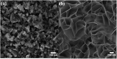 | ||
| Fig. 1 SEM images of (a) iron-incorporated nickel hydroxide (FeNi-10) and (b) pristine nickel hydroxide (FeNi-0) films. | ||
As a result of the difference in the solubility of iron and nickel hydroxides and the variation in iron and nickel concentrations during the deposition step, it is highly expected that the iron/nickel ratio in the grown films is not the same as that in the solution-based chemical deposition bath. Thus, the real concentrations of iron and nickel in the fabricated electrocatalyst electrodes were determined by ICP-OES, and the data analysis is presented in Table 1. It was found that the concentration of iron in the grown films is higher than that expected from the iron concentration in the chemical bath. This observation is similar to that found for the electrochemically deposited iron-incorporated nickel hydroxide films; however, the iron concentrations in the electrochemically deposited films were less than expected.45 The most electrochemically active film (i.e., FeNi-10) was characterized by XPS. Fig. 2a shows the deconvoluted XPS peaks of Fe 2p3/2 and Fe 2p1/2 core levels positioned at 710.2 and 723.2 eV, respectively. These two peaks can be readily detected and they are separated from the peak of Sn 2p (originating from the F–SnO2 on the conductive glass).46 They are also separated by a split spin–orbit component of 13.0 eV evincing the existence of Fe in the +3 oxidation state in the form of hydroxide. Fig. 2b displays the typical XPS spectrum of the Ni 2p core level in the hydroxide form. It has two peaks, one is positioned at 855.3 eV for Ni 2p3/2, and the other peak located at 872.6 eV is for Ni 2p1/2 and they are separated by a split spin–orbit component of 17.3 eV indicating the presence of Ni in the +2 oxidation state.46
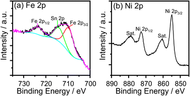 | ||
| Fig. 2 XPS core-level spectra of (a) Fe 2p and (b) Ni 2p in iron-incorporated nickel hydroxide (FeNi-10) film. | ||
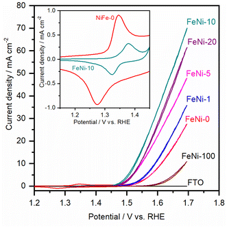
To assess the electrocatalytic performance of the fabricated electrodes toward the OER in an alkaline medium, the LSV polarization curves were measured and are presented in Fig. 3. It was noticed that, with increasing the ratio of iron in the chemical deposition bath, the obtained electrocatalyst exhibited increased electrocatalytic OER activity up to 10 at% Fe. At higher Fe concentrations, the electrocatalytic activity is diminished. This trend agrees with the behavior reported for NiFe-based oxyhydroxide electrocatalyst films deposited by electrochemical deposition techniques.35,47 It was commonly observed that the presence of iron in the chemical bath greatly influences the activity and reduces the onset potential for the water oxidation reaction. For a clear comparison, the OER overpotential at 10 mA cm−2 for the prepared electrocatalyst electrodes was measured and is presented in Table 1.
It was noticed that the OER overpotential on the pristine nickel hydroxide electrocatalyst at 10 mA cm−2 is 384 mV. Then, it gradually decreases as the content of iron in the chemical deposition bath increases up to 10 at%. Interestingly, the OER overpotential is significantly reduced, reaching 290 mV over the FeNi-10 electrocatalyst. This value is among the lowest reported values for the oxygen evolution electrocatalyst deposited on plane surfaces such as FTO glass.49,50 For a more detailed comparison, the electrochemical and kinetics parameters for the OER in an alkaline medium on some state-of-the-art FeNi-based (oxy)hydroxide catalysts immobilized on flat substrates are presented in Table 1. At higher iron content in the chemical bath, the deposited iron-incorporated nickel hydroxide film showed higher overpotential for water oxidation. This is attributed to the fact that the solubility of iron in the nickel oxyhydroxides is confined in the range from 11 to 25%,51,52 and thus at high iron concentration, iron begins to separate into less electrocatalytic active iron oxyhydroxide and/or iron hydroxide domains. As a result, the OER efficiency of the electrodes with high iron content is reduced and the OER overpotential is increased.
The cyclic voltammogram (CV) of the FeNi-0 electrode presented in the inset of Fig. 3 exhibits the characteristic peaks of the α-Ni(OH)2/γ-NiOOH redox couple centered at ca. 1.35 VRHE. The same peaks can also be seen in the FeNi-10 cyclic voltammogram, but their area is smaller and they are anodically shifted. This behavior agrees with the previous report by Louie and Bell.45 By integrating the CV peaks of the α-Ni(OH)2/γ-NiOOH redox couple, the thickness of the effective electrocatalyst film can be calculated assuming 1 e− per Ni atom, and the density of nickel hydroxide is 4.1 g cm−3. It was found that the effective film thickness is 4 nm. The thickness of the deposited nickel hydroxide film was also calculated from the ICP-OES data. The areal loading was first calculated and found to be 176 μg cm−2. Assuming the deposited nickel hydroxide film exhibits a smooth and homogeneous surface and by knowing the density and molecular weight of nickel hydroxide, the thickness of the deposited nickel hydroxide (NiFe-0) film was calculated and found to be 430 nm. The areal loading of iron-incorporated nickel hydroxide (FeNi-10) was also determined to be 37 μg cm−2 and the thickness of the deposited FeNi-10 was calculated in the same manner and found to be 95 nm. Interestingly, the FeNi-10 film is transparent, and it has more or less equivalent transparency to that of FTO, as shown in Fig. 4. The transmittance is significantly reduced when pristine nickel hydroxide is deposited in agreement with the calculated film thickness. The fabrication of transparent and highly active electrocatalyst film is desirable for tandem photoelectrochemical water-splitting devices to minimize the light absorption by the electrocatalyst loaded on the surface of the photoelectrode.39
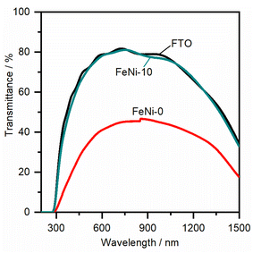 | ||
| Fig. 4 Transmittance spectra of the FTO substrate, pristine nickel hydroxide (FeNi-0), and iron-incorporated nickel hydroxide (FeNi-10) films deposited on FTO glass. | ||
To gain a further understanding of the pathways and the rate-determining step (RDS) of water oxidation reaction over the fabricated electrodes, the Tafel plots were constructed from the LSV curves measured at a slow scan rate (1.0 mV s−1) to ensure the steady-state current condition. The Tafel plots of FeNi-0 and FeNi-10 electrocatalyst electrodes are presented in Fig. 5 as an example. The linear parts of the plots were fitted using the linear regression method. By comparison with the Tafel equation (η = a + b × log(j)), the Tafel slope (b) is obtained from the linear regression fitting parameters and presented in Table 1. The Tafel slope of the pristine nickel hydroxide electrocatalyst electrode (FeNi-0) was found to be 70 mV dec−1. In general, the Tafel slope can be used to differentiate between different reaction pathways and define the RDS. The experimental Tafel slope is given by the following equation b = 2.303 × (RT/![[small alpha, Greek, vector]](https://www.rsc.org/images/entities/i_char_e118.gif) F) where R, T, and F have their general meaning (i.e., gas constant, temperature, and Faraday constant, respectively),53 whereas the transfer coefficient (
F) where R, T, and F have their general meaning (i.e., gas constant, temperature, and Faraday constant, respectively),53 whereas the transfer coefficient (![[small alpha, Greek, vector]](https://www.rsc.org/images/entities/i_char_e118.gif) ) is expressed by
) is expressed by ![[small alpha, Greek, vector]](https://www.rsc.org/images/entities/i_char_e118.gif) = (
= (![[n with combining right harpoon above (vector)]](https://www.rsc.org/images/entities/i_char_006e_20d1.gif) /ν) + nrβ where
/ν) + nrβ where ![[n with combining right harpoon above (vector)]](https://www.rsc.org/images/entities/i_char_006e_20d1.gif) is the number of transferred electrons before the RDS, ν is the stoichiometric number, nr is the number of electrons involved in the RDS, and β is the symmetry factor. If the RDS includes a chemical step after the first electron transfer, it is reasonable to set nr = 0 and
is the number of transferred electrons before the RDS, ν is the stoichiometric number, nr is the number of electrons involved in the RDS, and β is the symmetry factor. If the RDS includes a chemical step after the first electron transfer, it is reasonable to set nr = 0 and ![[n with combining right harpoon above (vector)]](https://www.rsc.org/images/entities/i_char_006e_20d1.gif) = 1. Assuming the stoichiometric number of the first electron transfer elementary step is one, a Tafel slope value of 60 mV dec−1 can be calculated. This value is close to the obtained Tafel slope value (70 mV dec−1) for the FeNi-0 electrode, suggesting that the mechanism of the OER on this electrode includes a chemical transformation step, more likely a Ni(OH)2/NiOOH step, as the RDS step following the first electron transfer.53 The incorporation of iron into the nickel hydroxide electrocatalyst resulted in a gradual decrease in the Tafel slope values from 70 mV dec−1 for FeNi-0 to 37 mV dec−1 for the FeNi-20 electrode. This trend agrees well with the observed reduction in the OER overpotentials at 10 mA cm−2, extracted from the LSV voltammograms, presented in Table 1, and it can be explained based on the microkinetic analysis model by Shinagawa et al.54 This model predicted that in the early stage of the OER if the surface adsorbed intermediates are predominant, the Tafel slope will decrease. The mechanistic study by Friebel et al.52 indicated that the intermediates formed during the OER are adsorbed too weakly on the pristine nickel oxyhydroxide electrocatalyst, while they adsorbed too strongly on the pure iron oxyhydroxide electrocatalyst. The optimal binding energies for the OER intermediates were found to occur at the iron sites that are surrounded by Ni and the RDS is the step that involves the formation of the OOH intermediate.50 Based on this analysis model, it is reasonable to conclude here that the observed decrease in the Tafel slope upon the incorporation of iron into the nickel hydroxide films is attributed to the formation of surface-adsorbed OER intermediates with optimized binding energy. The inclusion of Fe3+ into the NiOOH lattice creates nearly optimal adsorption energies for the OER intermediates on iron sites and facilitates the formation of the O–O bond.35,36 It also induces the rearrangement of the electron distribution between Ni and O and increases the Ni reducibility, thus improving the OER rate.27 Thus it is reasonable to assume that the Ni sites are the actual active sites for the OER and the incorporation of Fe3+ ions into nickel hydroxide creates optimal binding energy for the intermediates.
= 1. Assuming the stoichiometric number of the first electron transfer elementary step is one, a Tafel slope value of 60 mV dec−1 can be calculated. This value is close to the obtained Tafel slope value (70 mV dec−1) for the FeNi-0 electrode, suggesting that the mechanism of the OER on this electrode includes a chemical transformation step, more likely a Ni(OH)2/NiOOH step, as the RDS step following the first electron transfer.53 The incorporation of iron into the nickel hydroxide electrocatalyst resulted in a gradual decrease in the Tafel slope values from 70 mV dec−1 for FeNi-0 to 37 mV dec−1 for the FeNi-20 electrode. This trend agrees well with the observed reduction in the OER overpotentials at 10 mA cm−2, extracted from the LSV voltammograms, presented in Table 1, and it can be explained based on the microkinetic analysis model by Shinagawa et al.54 This model predicted that in the early stage of the OER if the surface adsorbed intermediates are predominant, the Tafel slope will decrease. The mechanistic study by Friebel et al.52 indicated that the intermediates formed during the OER are adsorbed too weakly on the pristine nickel oxyhydroxide electrocatalyst, while they adsorbed too strongly on the pure iron oxyhydroxide electrocatalyst. The optimal binding energies for the OER intermediates were found to occur at the iron sites that are surrounded by Ni and the RDS is the step that involves the formation of the OOH intermediate.50 Based on this analysis model, it is reasonable to conclude here that the observed decrease in the Tafel slope upon the incorporation of iron into the nickel hydroxide films is attributed to the formation of surface-adsorbed OER intermediates with optimized binding energy. The inclusion of Fe3+ into the NiOOH lattice creates nearly optimal adsorption energies for the OER intermediates on iron sites and facilitates the formation of the O–O bond.35,36 It also induces the rearrangement of the electron distribution between Ni and O and increases the Ni reducibility, thus improving the OER rate.27 Thus it is reasonable to assume that the Ni sites are the actual active sites for the OER and the incorporation of Fe3+ ions into nickel hydroxide creates optimal binding energy for the intermediates.
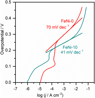 | ||
| Fig. 5 Tafel plots of pristine nickel hydroxide (FeNi-0) and iron-incorporated nickel hydroxide (FeNi-10) electrocatalysts measured in an alkaline medium (1.0 M NaOH) at 1.0 mV s−1 scan rate. | ||
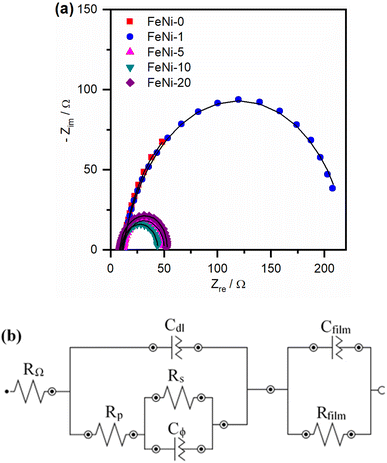
To further explore the influence of iron incorporation into the nickel hydroxide films on the rate of the OER, the intermediates' formation resistance and charge transfer resistance have been evaluated using the electrochemical impedance spectroscopy (EIS) technique. The Nyquist plots of the fabricated electrodes were measured and are presented in Fig. 6a. A significant decrease in the size of the semi-circle was observed upon the incorporation of iron into the nickel hydroxide electrocatalyst film. This trend agrees with the decreased OER overpotential observed in the polarization curves presented in Fig. 3 and the reported values tabulated in Table 1. The smallest semi-circle was observed for the FeNi-10 electrocatalyst. In general, the small semi-circle is an indication of the high conductivity of the electrode, the low resistance for the formation of the intermediates, and the facile charge transfer at the electrode/electrolyte interface. For more details, the Nyquist plots presented in Fig. 6 were fitted using the Nova Autolab software using the equivalent circuit (EC) given in Fig. 6b which is commonly employed to model the OER during the fitting procedure.35,55
The CfilmRfilm loop in this EC represents the dielectric properties and the resistivity of the electrocatalyst film. The Cdl and RΩ elements symbolize the double-layer capacitance and electrolyte resistance, respectively. The Rp element is the polarization resistance which is the resistance associated with the overall charge transfer of the different steps of the OER including the RDS, while Rs represents the resistance associated with the formation of the OER intermediates. Cϕ is the capacitance associated with the catalyst active sites where the OER takes place. The RsCϕ loop represents thus the time constant of the relaxation of charge associated with the formation of surface intermediates, while Rs together with Rp represents the resistance of the faradaic electrocatalytic OER (RFar = Rs + Rp). Fig. 7a and b show the values of Rs and RFar resulting from the fitting of Nyquist plots to the EC displayed in Fig. 6b. It was noticed that with increasing the ratio of iron in the electrocatalyst films, the magnitude of Rs and RFar decreased with a minimum value observed for the FeNi-10 electrode. This behaviour agrees with the electrocatalytic activity observed in Fig. 3. The high Rs value of the pristine nickel hydroxide (FeNi-0) electrocatalyst reveals that the formation of OER intermediates is unfavorable, which complies with the report that the OER intermediates are adsorbed too weakly on the pristine nickel oxyhydroxide electrocatalyst.52 It seems that the incorporation of iron into the nickel hydroxide films indeed reduces the Rs and creates optimal adsorption energies for the formation of O–O intermediates.35,36,52 It increases the Ni reducibility, thus improving the OER activity.27 The slight increase of the Rs value observed at a higher iron concentration (FeNi-20) might be attributed to the segregation of iron active sites into less active FeOOH domains. It also decreases the overall charge transfer resistance for the OER, as can be concluded from the RFar values presented in Fig. 7b.
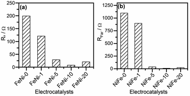 | ||
| Fig. 7 (a) Intermediates' formation resistance (Rs) and (b) the faradaic resistance (RFar = Rs + Rp) for pristine and iron-incorporated nickel hydroxide electrodes calculated by fitting the Nyquist plots presented in Fig. 6a with the EC in Fig. 6b. | ||
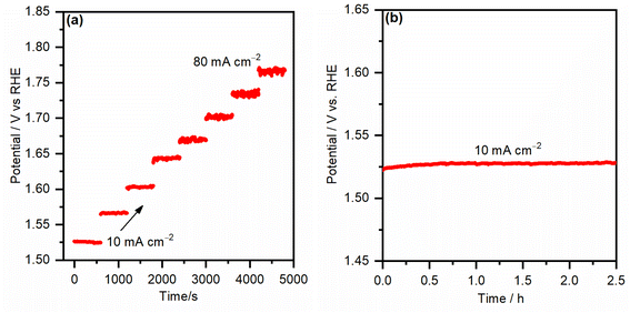
To test the mass transport properties of the inward OH− diffusion and the oxygen bubble removal on the most active iron-incorporated nickel hydroxide electrocatalyst electrode (NiFe-10), the multi-step chronopotentiometric curve was measured and is presented in Fig. 8a. The starting current was adjusted to be 10 mA cm−2 and increased by the same value every 600 s. Immediately after applying the current for the first step, the potential increased, even reaching 1.52 VRHE, and continued smoothly for the rest of the 600 s. Analogous behaviors were seen for all steps of the applied current up to 80 mA cm−2, evincing that the FeNi-10 exhibits outstanding mass transport properties.38 The fast chronopotentiometric responses further indicate the good conductivity and adhesion of the FeNi-10 electrode. The stability of the FeNi-10 electrode was further investigated for a longer time (see Fig. 8b). It was observed that the potential required to deliver 10 mA cm−2 is stable and fluctuates within a very small voltage range evincing the stability of the synthesized transparent electrode. The composition and areal loading after the stability test were tested. It was found that the latter is 35 μg cm−2 which is almost the same as before the test (37 μg cm−2), further evincing the stability of the electrode. The composition analysis indicated that the iron content has increased, likely due to the iron uptake from the electrolyte solution (iron in NaOH electrolyte) as previously observed.51
4. Conclusions
In summary, we demonstrated a facile and low-temperature solution-based synthetic route for fabricating transparent iron-incorporated nickel hydroxide electrodes with efficient electrocatalytic activity for water oxidation. The developed synthetic route depends on lowering the water–iron/nickel hydroxide nanocrystals' interfacial tension. This allows the control of the nucleation, growth, and ripening processes. Based on this approach and using hexamethylenetetramine as a reagent for in situ raising the pH of the chemical bath at a relatively low temperature (90 °C), iron-incorporated nickel hydroxide nanoplatelet films with different ratios of iron content were synthesized. The successful incorporation of iron into this unique nanostructured nickel hydroxide electrocatalyst film leads to a steady and stable current generation at low overpotential (i.e., 10 mA cm−2 at 290 mV). The Tafel slope of the most active and fully transparent iron-incorporated nickel hydroxide electrode was found to be 41 mV dec−1. The achieved values for the overpotential and Tafel slope are among the lowest ones reported for OER electrocatalysts. They are even better than those reported for RuO2 and IrO2 oxides immobilized on the FTO substrate. The small overpotential and the low Tafel slope observed on the iron-incorporated nickel hydroxide films are attributed to the reduced resistance for the formation of surface-adsorbed OER intermediates and the improved conductivity of the electrocatalyst films, as confirmed by the EIS analysis. The developed electrocatalyst films are fully transparent and have potential application in fabricating a tandem device for photoelectrochemical water splitting.Conflicts of interest
There are no conflicts to declare.Acknowledgements
T. A. K acknowledges the support provided by the Deanship of Scientific Research (DSR) at King Fahd University of Petroleum & Minerals (KFUPM) through Project No. DF201010.References
- L. Schlapbach and A. Zuttel, Hydrogen-Storage Materials for Mobile Applications, Nature, 2001, 414(6861), 353–358 CrossRef CAS PubMed.
- J. Graetz, New Approaches to Hydrogen Storage, Chem. Soc. Rev., 2009, 38(1), 73–82 RSC.
- H. Song, S. Luo, H. Huang, B. Deng and J. Ye, Solar-Driven Hydrogen Production: Recent Advances, Challenges, and Future Perspectives, ACS Energy Lett., 2022, 7(3), 1043–1065 CrossRef CAS.
- IEA, The Future of Hydrogen, IEA, Paris, 2019, https://www.iea.org/reports/the-future-of-hydrogen, License: CC BY 4.0 Search PubMed.
- N. S. Lewis and D. G. Nocera, Powering the Planet: Chemical Challenges in Solar Energy Utilization, Proc. Natl. Acad. Sci. U. S. A., 2006, 103(43), 15729–15735 CrossRef CAS PubMed.
- S. Pan, R. Li, Q. Zhang, C. Cui, M. Wang, B. Shi, P. Wang, C. Zhang, B. Zhang, Y. Zhao and X. Zhang, An over 20% Solar-to-Hydrogen Efficiency System Comprising a Self-Reconstructed NiCoFe-Based Hydroxide Nanosheet Electrocatalyst and Monolithic Perovskite/Silicon Tandem Solar Cell, J. Mater. Chem. A, 2021, 9(24), 14085–14092 RSC.
- T. J. Jacobsson, V. Fjällström, M. Sahlberg, M. Edoff and T. Edvinsson, A Monolithic Device for Solar Water Splitting Based on Series Interconnected Thin Film Absorbers Reaching over 10% Solar-to-Hydrogen Efficiency, Energy Environ. Sci., 2013, 6(12), 3676–3683 RSC.
- J. R. McKone, N. S. Lewis and H. B. Gray, Will Solar-Driven Water-Splitting Devices See the Light of Day?, Chem. Mater., 2014, 26(1), 407–414 CrossRef CAS.
- C. C. L. McCrory, S. Jung, J. C. Peters and T. F. Jaramillo, Benchmarking Heterogeneous Electrocatalysts for the Oxygen Evolution Reaction, J. Am. Chem. Soc., 2013, 135(45), 16977–16987 CrossRef CAS PubMed.
- A. H. Al-Naggar, N. M. Shinde, J.-S. Kim and R. S. Mane, Water Splitting Performance of Metal and Non-Metal-Doped Transition Metal Oxide Electrocatalysts, Coord. Chem. Rev., 2023, 474, 214864 CrossRef CAS.
- M. W. Kanan and D. G. Nocera, In Situ Formation of an Oxygen-Evolving Catalyst in Neutral Water Containing Phosphate and Co2+, Science, 2008, 321(5892), 1072–1075 CrossRef CAS PubMed.
- M. T. M. Koper, Thermodynamic Theory of Multi-Electron Transfer Reactions: Implications for Electrocatalysis, J. Electroanal. Chem., 2011, 660(2), 254–260 CrossRef CAS.
- T. Reier, M. Oezaslan and P. Strasser, Electrocatalytic Oxygen Evolution Reaction (OER) on Ru, Ir, and Pt Catalysts: A Comparative Study of Nanoparticles and Bulk Materials, ACS Catal., 2012, 2(8), 1765–1772 CrossRef CAS.
- R. Zhang, L. Pan, B. Guo, Z. F. Huang, Z. Chen, L. Wang, X. Zhang, Z. Guo, W. Xu, K. P. Loh and J. J. Zou, Tracking the Role of Defect Types in Co3O4 Structural Evolution and Active Motifs During Oxygen Evolution Reaction, J. Am. Chem. Soc., 2023, 145(4), 2271–2281 CrossRef CAS PubMed.
- X. Deng and H. Tüysüz, Cobalt-Oxide-Based Materials as Water Oxidation Catalyst: Recent Progress and Challenges, ACS Catal., 2014, 4(10), 3701–3714 CrossRef CAS.
- Y. Zhou, Z. Zhou, L. Hu, R. Tian, Y. Wang, H. Arandiyan, F. Chen, M. Li, T. Wan, Z. Han, Z. Ma, X. Lu, C. Cazorla, T. Wu and D. Chu, A Facile Approach to Tailor Electrocatalytic Properties of MnO2 through Tuning Phase Transition, Surface Morphology and Band Structure, Chem. Eng. J., 2022, 438, 135561 CrossRef CAS.
- S. Zou, M. S. Burke, M. G. Kast, J. Fan, N. Danilovic and S. W. Boettcher, Fe (Oxy)Hydroxide Oxygen Evolution Reaction Electrocatalysis: Intrinsic Activity and the Roles of Electrical Conductivity, Substrate, and Dissolution, Chem. Mater., 2015, 27(23), 8011–8020 CrossRef CAS.
- M. D. Obradović and S. L. Gojković, Challenges in Determining the Electrochemically Active Surface Area of Ni-Oxides in the Oxygen Evolution Reaction, J. Electroanal. Chem., 2022, 918, 116479 CrossRef.
- L.-A. Stern and X. Hu, Enhanced Oxygen Evolution Activity by NiOx and Ni(OH)2 Nanoparticles, Faraday Discuss., 2014, 176, 363–379 RSC.
- K. Yan, M. Sheng, X. Sun, C. Song, Z. Cao and Y. Sun, Microwave Synthesis of Ultrathin Nickel Hydroxide Nanosheets with Iron Incorporation for Electrocatalytic Water Oxidation, ACS Appl. Energy Mater., 2019, 2(3), 1961–1968 CrossRef CAS.
- N. M. Shinde, S. D. Raut, B. G. Ghule, K. C. Gunturu, J. J. Pak and R. S. Mane, Recasting Ni-Foam into NiF2 Nanorod Arrays via a Hydrothermal Process for Hydrogen Evolution Reaction Application, Dalton Trans., 2021, 50(19), 6500–6505 RSC.
- T. A. Kandiel, Iron-Incorporated NiS/Ni(OH)2 Composite as an Efficient Electrocatalyst for Hydrogen Evolution Reaction from Water in a Neutral Medium, Appl. Catal., A, 2019, 586, 117226 CrossRef CAS.
- Y. Cao, Y. Su, L. Xu, X. Yang, Z. Han, R. Cao and G. Li, Oxygen Vacancy-Rich Amorphous FeNi Hydroxide Nanoclusters as an Efficient Electrocatalyst for Water Oxidation, J. Energy Chem., 2022, 71, 167–173 CrossRef CAS.
- B. Wang, C. Tang, H.-F. Wang, X. Chen, R. Cao and Q. Zhang, Core-Branch CoNi Hydroxysulfides with Versatilely Regulated Electronic and Surface Structures for Superior Oxygen Evolution Electrocatalysis, J. Energy Chem., 2019, 38, 8–14 CrossRef.
- Y.-X. Zhu, M. Liu, G.-Y. Hou, Y.-P. Tang and L.-K. Wu, The Release of Metal Ions Induced Surface Reconstruction of Layered Double Hydroxide Electrocatalysts, Sustainable Energy Fuels, 2021, 5(13), 3436–3444 RSC.
- G. P. Kharabe, R. Illathvalappil, S. Barik, F. Kanheerampockil, P. S. Walko, S. K. Bhat, R. N. Devi and S. Kurungot, A Cobalt–Manganese Modified Theophrastite Phase of Nickel Hydroxide Nanoflower Arrays on Nickel Foam as a Self-Standing Bifunctional Electrode for Overall Water Electrolysis, Sustainable Energy Fuels, 2023, 7(10), 2428–2440 RSC.
- C. Kuai, C. Xi, A. Hu, Y. Zhang, Z. Xu, D. Nordlund, C.-J. Sun, C. A. Cadigan, R. M. Richards, L. Li, C.-K. Dong, X.-W. Du and F. Lin, Revealing the Dynamics and Roles of Iron Incorporation in Nickel Hydroxide Water Oxidation Catalysts, J. Am. Chem. Soc., 2021, 143(44), 18519–18526 CrossRef CAS PubMed.
- S. Bulakhe, N. Shinde, J.-S. Kim, R. S. Mane and R. Deokate, Recent Advances in Non-Precious Ni-Based Promising Catalysts for Water Splitting Application, Int. J. Energy Res., 2022, 46(13), 17829–17847 CrossRef CAS.
- Y. Hao, Y. Li, J. Wu, L. Meng, J. Wang, C. Jia, T. Liu, X. Yang, Z. P. Liu and M. Gong, Recognition of Surface Oxygen Intermediates on NiFe Oxyhydroxide Oxygen-Evolving Catalysts by Homogeneous Oxidation Reactivity, J. Am. Chem. Soc., 2021, 143(3), 1493–1502 CrossRef CAS PubMed.
- H. Qian, J. Wei, C. Yu, F. Tang, W. Jiang, D. Xia and L. Gan, In Situ Quantification of the Active Sites, Turnover Frequency, and Stability of Ni–Fe (Oxy)Hydroxides for the Oxygen Evolution Reaction, ACS Catal., 2022, 12(22), 14280–14289 CrossRef CAS.
- P. M. Bodhankar, P. B. Sarawade, G. Singh, A. Vinu and D. S. Dhawale, Recent Advances in Highly Active Nanostructured NiFe LDH Catalyst for Electrochemical Water Splitting, J. Mater. Chem. A, 2021, 9(6), 3180–3208 RSC.
- A. Hickling and S. Hill, Oxygen Overvoltage. 1. The Influence of Electrode Material, Current Density, and Time in Aqueous Solution, Discuss. Faraday Soc., 1947, 1, 236–246 RSC.
- R. L. Tichenor, Nickel Oxides – Relation between Electrochemical Reactivity and Foreign Ion Content, Ind. Eng. Chem., 1952, 44(5), 973–977 CrossRef CAS.
- L. Trotochaud, S. L. Young, J. K. Ranney and S. W. Boettcher, Nickel–Iron Oxyhydroxide Oxygen-Evolution Electrocatalysts: The Role of Intentional and Incidental Iron Incorporation, J. Am. Chem. Soc., 2014, 136(18), 6744–6753 CrossRef CAS PubMed.
- J. R. Swierk, S. Klaus, L. Trotochaud, A. T. Bell and T. D. Tilley, Electrochemical Study of the Energetics of the Oxygen Evolution Reaction at Nickel Iron (Oxy)Hydroxide Catalysts, J. Phys. Chem. C., 2015, 119(33), 19022–19029 CrossRef CAS.
- Z. K. Goldsmith, A. K. Harshan, J. B. Gerken, M. Vörös, G. Galli, S. S. Stahl and S. Hammes-Schiffer, Characterization of NiFe Oxyhydroxide Electrocatalysts by Integrated Electronic Structure Calculations and Spectroelectrochemistry, Proc. Natl. Acad. Sci. U. S. A., 2017, 114(12), 3050–3055 CrossRef CAS PubMed.
- E. Nurlaela, T. Shinagawa, M. Qureshi, D. S. Dhawale and K. Takanabe, Temperature Dependence of Electrocatalytic and Photocatalytic Oxygen Evolution Reaction Rates Using NiFe Oxide, ACS Catal., 2016, 6(3), 1713–1722 CrossRef CAS.
- X. Lu and C. Zhao, Electrodeposition of Hierarchically Structured Three-Dimensional Nickel–Iron Electrodes for Efficient Oxygen Evolution at High Current Densities, Nat. Commun., 2015, 6, 6616 CrossRef CAS PubMed.
- C. G. Morales-Guio, M. T. Mayer, A. Yella, S. D. Tilley, M. Grätzel and X. Hu, An Optically Transparent Iron Nickel Oxide Catalyst for Solar Water Splitting, J. Am. Chem. Soc., 2015, 137(31), 9927–9936 CrossRef CAS PubMed.
- W. D. Chemelewski, H.-C. Lee, J.-F. Lin, A. J. Bard and C. B. Mullins, Amorphous FeOOH Oxygen Evolution Reaction Catalyst for Photoelectrochemical Water Splitting, J. Am. Chem. Soc., 2014, 136(7), 2843–2850 CrossRef CAS PubMed.
- W. D. Chemelewski, J. R. Rosenstock and C. B. Mullins, Electrodeposition of Ni-Doped FeOOH Oxygen Evolution Reaction Catalyst for Photoelectrochemical Water Splitting, J. Mater. Chem. A, 2014, 2(36), 14957–14962 RSC.
- L. Vayssieres, N. Beermann, S. E. Lindquist and A. Hagfeldt, Controlled Aqueous Chemical Growth of Oriented Three-Dimensional Crystalline Nanorod Arrays: Application to Iron(III) Oxides, Chem. Mater., 2001, 13(2), 233–235 CrossRef CAS.
- L. Vayssieres, An Aqueous Solution Approach to Advanced Metal Oxide Arrays on Substrates, Appl. Phys. A: Mater. Sci. Process., 2007, 89(1), 1–8 CrossRef CAS.
- V. Strano, R. G. Urso, M. Scuderi, K. O. Iwu, F. Simone, E. Ciliberto, C. Spinella and S. Mirabella, Double Role of HMTA in ZnO Nanorods Grown by Chemical Bath Deposition, J. Phys. Chem. C, 2014, 118(48), 28189–28195 CrossRef CAS.
- M. W. Louie and A. T. Bell, An Investigation of Thin-Film Ni–Fe Oxide Catalysts for the Electrochemical Evolution of Oxygen, J. Am. Chem. Soc., 2013, 135(33), 12329–12337 CrossRef CAS PubMed.
- J. F. Moudlar, W. F. Stickle, P. E. Sobol and K. D. Bomben, Handbook of X-Ray Photoelectron Spectroscopy, Physical Electronics, Inc., United State of America, 1995 Search PubMed.
- X. Li, F. C. Walsh and D. Pletcher, Nickel Based Electrocatalysts for Oxygen Evolution in High Current Density, Alkaline Water Electrolysers, Phys. Chem. Chem. Phys., 2011, 13(3), 1162–1167 RSC.
- N.-T. Suen, S.-F. Hung, Q. Quan, N. Zhang, Y.-J. Xu and H.M. Chen, Electrocatalysis for the Oxygen Evolution Reaction: Recent Development and Future Perspectives, Chem. Soc. Rev., 2017, 46, 337–365 RSC.
- N.-T. Suen, S.-F. Hung, Q. Quan, N. Zhang, Y.-J. Xu and H. M. Chen, Electrocatalysis for the Oxygen Evolution Reaction: Recent Development and Future Perspectives, Chem. Soc. Rev., 2017, 46(2), 337–365 RSC.
- F. Dionigi and P. Strasser, NiFe-Based (Oxy)Hydroxide Catalysts for Oxygen Evolution Reaction in Non-Acidic Electrolytes, Adv. Energy Mater., 2016, 6(23), 1600621 CrossRef.
- S. Klaus, Y. Cai, M. W. Louie, L. Trotochaud and A. T. Bell, Effects of Fe Electrolyte Impurities on Ni(OH)2/NiOOH Structure and Oxygen Evolution Activity, J. Phys. Chem. C, 2015, 119(13), 7243–7254 CrossRef CAS.
- D. Friebel, M. W. Louie, M. Bajdich, K. E. Sanwald, Y. Cai, A. M. Wise, M.-J. Cheng, D. Sokaras, T.-C. Weng, R. Alonso-Mori, R. C. Davis, J. R. Bargar, J. K. Nørskov, A. Nilsson and A. T. Bell, Identification of Highly Active Fe Sites in (Ni,Fe)OOH for Electrocatalytic Water Splitting, J. Am. Chem. Soc., 2015, 137(3), 1305–1313 CrossRef CAS PubMed.
- R. L. Doyle, I. J. Godwin, M. P. Brandon and M. E. G. Lyons, Redox and Electrochemical Water Splitting Catalytic Properties of Hydrated Metal Oxide Modified Electrodes, Phys. Chem. Chem. Phys., 2013, 15(33), 13737–13783 RSC.
- T. Shinagawa, A. T. Garcia-Esparza and K. Takanabe, Insight on Tafel Slopes from a Microkinetic Analysis of Aqueous Electrocatalysis for Energy Conversion, Sci. Rep., 2015, 5, 13801 CrossRef PubMed.
- C. G. Morales-Guio, L. Liardet and X. Hu, Oxidatively Electrodeposited Thin-Film Transition Metal (Oxy)Hydroxides as Oxygen Evolution Catalysts, J. Am. Chem. Soc., 2016, 138(28), 8946–8957 CrossRef CAS PubMed.
| This journal is © The Royal Society of Chemistry 2023 |

