A thermoelectric energy harvesting system for pavements with a fin cooling structure
Jian
Wei
 *,
Jiawei
Hui
,
Taotao
Wang
,
Yuan
Wang
,
Yupeng
Guo
,
Siqing
Zhang
,
Yanbin
Zhang
and
Xinyu
Qiao
College of Materials Science and Engineering, Xi'an University of Architecture and Technology, Xi'an, 710055, China. E-mail: weijian@xauat.edu.cn; Fax: +86 29 82205245; Tel: +86 29 82201721
First published on 5th December 2022
Abstract
By using thermoelectric technology, the heat of the road can be collected and converted into electricity. However, the current pavement thermoelectric energy harvesting system (TEHS) has problems such as a low road utilization rate, high power generation cost, and complex structure that cannot be applied on a large scale, which limit its further development. In this paper, a multi-layer TEHS for pavements is proposed. The design of this multilayer structural board provides more space for thermoelectric generators (TEGs) without increasing the road area, which significantly improves the utilization rate of the road and the power generation. Aluminum fins are used as heat dissipation components to greatly reduce costs and facilitate installation. The optimal structure size of the TEHS is obtained by finite element heat transfer analysis, verified by an experimental study. The results show that the highest generation voltage can reach 0.3 V, which means that 16.94 kW h power can be effectively collected from a road with a length of 1 km and a width of 10 m within 6 hours. This research is of great significance for the TEHS to improve road utilization and reduce power generation costs, and for large-scale utilization.
1. Introduction
In the international background of the energy crisis,1 the development of new types of green and clean energy has become the most urgent goal.2–4 Roads, as an essential infrastructure in transportation, play a vital role in the development of modern society. Roads contain a lot of thermal energy due to prolonged exposure to solar radiation.5 Harvesting energy from pavements has shown the prospect of generating green electricity.6 There are many potential applications in harvesting and converting the heat energy into electricity, such as supplying power to street lamps, road health detection equipment, and road detection sensors.7 It can also provide electricity support for basic living for residents in some remote areas. Roads not only absorb heat during the day, but also release heat into the environment at night due to temperature differences, further exacerbating the urban heat island effect.8,9 The thermoelectric technology is successfully applied to the vast roads; it can not only absorb the heat from the roads, alleviate the urban heat island effect and improve the living conditions of residents, but also be a kind of non-consuming, pollution-free green clean energy.Thermoelectric energy harvesting devices usually use thermoelectric generators (TEGs) made of Bi2Te3 materials.10 TEGs have the advantages of small volume, high stability, no moving parts, maintenance-free, long service life, etc.11 The interior of TEGs is usually formed from many pairs of alternating N-type and P-type semiconductors in series.12 The principle of power generation is based on the Seebeck effect of semiconductors.13 As shown in Fig. 1,18 the generated electromotive force is calculated using the following formula (1):14
| V = α(Th − Tc) | (1) |
 | (2) |
 | (3) |
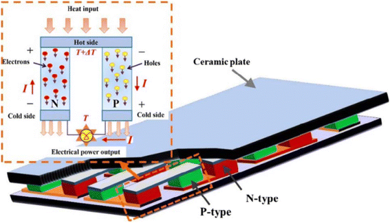 | ||
| Fig. 1 Seebeck effect of a TEG module.18 | ||
It can be seen from formula (3) that the temperature difference between the hot and cold ends of the TEG determines its power generation efficiency. The key to improving the efficiency of thermoelectric conversion is to reduce the cold end temperature as much as possible when the hot end temperature is determined.
In the design of the pavement thermoelectric energy harvesting system (TEHS), pipes and metal plates are usually buried in roads as hot ends of the TEG to transfer heat, while the cooling mode at the cold end is different. For the first time, in 2006, Hasebe et al. designed a pavement pipe thermal energy harvesting system.19 A layer of pipe is laid under the road and equipped with a pump to supply water to the pipe. The water flow in the pipes is heated by solar radiation to serve as the hot end of the TEG. The river near the road serves as the cold end to dissipate heat, and the temperature difference generated is used to generate electricity. However, the pipeline suffers from leakage and other problems which limit its further development. In 2012, Wu designed a TEHS with an aluminum rod structure.20 The aluminum rod is inserted directly into the asphalt, a TEG is placed on the top of the aluminum rod, and the temperature difference between the aluminum rod and the TEG is used to generate electricity. Datta et al. in 2017 studied a TEHS with a Z-shaped copper plate.21 The TEG is not directly buried in the center of the road, but on both sides. The heat in the road is collected by the copper plate and transferred to the hot end of the TEG. This design can not only protect the TEG from vehicle load damage, but also can avoid reducing the structural strength of the pavement. Other literature studies reported later have adopted similar designs. The cold end of the TEG uses a metal box filled with water to dissipate heat, which creates a temperature difference between the two ends to generate electricity. Jiang et al. designed a road TEHS based on a water tank in 2018.22 An aluminum vapor chamber is buried in the road to collect heat and transfer it to the TEG. At the same time, a row of water tanks is placed on both sides of the road to dissipate heat, and a sunshade is placed above the water tank to avoid heating up due to solar radiation. The results show that this design can maintain a significant temperature difference and significantly increase the power generation. Still, more cost is needed for the later maintenance of the water tank. Tahami et al. designed an L-shaped pavement TEHS in 2019 (ref. 23) and used copper plates to collect road heat at the hot end. The cold end adopts a heat dissipation module composed of a phase change material, an aerogel, a foam box and a PVC box. Finite element and field tests show that the phase change material can effectively reduce the temperature of the cold end, but the disadvantage is that the price is too high. Khamil et al. designed a pavement TEHS with an H-shaped aluminum plate structure in 2020.24 The aluminum plate is placed directly on the surface of the road to collect heat, and the cold end uses a combination of a large-size aluminum plate and an aluminum rod. However, because it is placed on the road surface, the TEHS can only be installed in the gaps between the roads and where there are no vehicles and pedestrians, which limits its large-scale application.
In a word, although the above TEHSs significantly improve power generation, they cannot be applied on a large scale due to their complex structure, high maintenance cost, easy leakage, and short life span. In this paper, a TEHS with a new multilayer structure is proposed, which provides more space for the installation of the TEG without increasing the road use area, and significantly improves the utilization rate of the road and the power generation. Aluminum fins are glued to the cold end of the TEG to dissipate heat. This simple structure facilitates installation and requires no maintenance. The focus of this study is to design a simple and practical pavement TEHS, and reduce the impact on the original pavement as much as possible.
2. Structure and construction
2.1 Structure
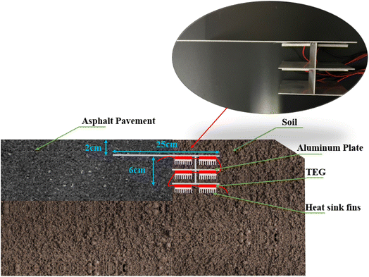
The overall structure of the TEHS is shown in Fig. 2, which is mainly composed of three parts:(1) Multi-layer structural aluminum plate buried in the depth of the road surface: the aluminum plate is divided into two parts, a heat collecting plate of 150 mm length, 80 mm width and 1.5 mm thickness, and a heat transfer plate of 100 mm length, 80 mm width and 1.5 mm thickness. About 2/3 of the length of the aluminum plate is buried under the asphalt road, and the remaining 1/3 is buried in the soil. Its primary function is to collect the heat from the road and transfer it to the hot end of the TEG. The heat transfer plate with a layered structure provides more space for the TEG without increasing the road area, thus improving the utilization rate of the road and the power generation. Aluminum is used as a heat/cold transfer material because it is an excellent thermal conductor, its weight is only half that of a copper conductor with the same conductivity, and the cost is low, so the TEHS uses aluminum plates to transfer heat. Jiang et al. have shown that the temperature at 2–3 cm below the asphalt road is 3–4 °C lower than at the surface,25 and the temperature at this depth does not fluctuate considerably. Therefore, it is best to embed the aluminum plate 2–3 cm below the asphalt road surface.
(2) Thermoelectric generators (TEGs): six TEGs (model number is 1-241-1.4-1.2) made of the Bi2Te3 material have a specific size of 50 × 50 × 3.6 mm. Each TEG has 241 thermocouples. The suitable temperature range is −60 to 125 °C. The hot end of the TEG is glued to the bottom of the heat transfer plate. When there is a temperature difference between the hot end and the cold end of the TEG, electricity will be generated. The greater the temperature difference, the higher the electricity. TEGs are connected in series to improve the power generation of the whole system. The TEG on the same layer can be regarded as a thermal parallel connection, and the thermal series between different layers.
(3) Heat dissipation components: the cold end of the TEG comprises an aluminum fin with the size of 50 × 50 × 15 mm, which is directly attached to the cold end of the TEG. The design of the fin structure facilitates quick export of the heat outward, to achieve the purpose of cooling.
2.2 Construction
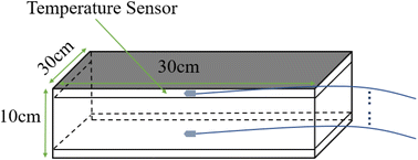
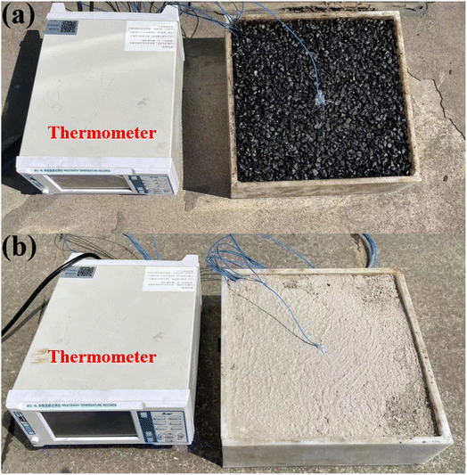
To compare the surface temperature and temperature gradients of different depths (10–70 mm), asphalt blocks and cement mortar blocks with the same structure size (300 mm × 300 mm × 100 mm) were prepared and tested indoors and outdoors respectively, and a BCL2008S thermometer was used to measure the temperature.In the process of roadblock preparation, the approach of layered paving and compaction was adopted, and k-type thermocouples were placed on the surface and at 10–70 mm depth to record the temperature. A total of 8 thermocouples are shown in Fig. 3 and 4. To verify which asphalt pavement or cement pavement is more suitable for the installation of the TEHS, the heat transfer performances of the asphalt pavement and cement pavement are compared, and the power generation is compared and analyzed in the following content. A cement block is made by the pouring process. During the pouring process, the mass ratio of the cement, mortar, and water is 1![[thin space (1/6-em)]](https://www.rsc.org/images/entities/char_2009.gif) :
:![[thin space (1/6-em)]](https://www.rsc.org/images/entities/char_2009.gif) 3
3![[thin space (1/6-em)]](https://www.rsc.org/images/entities/char_2009.gif) :
:![[thin space (1/6-em)]](https://www.rsc.org/images/entities/char_2009.gif) 0.6 (for the general cement road ratio standard), which are mixed evenly and poured into the mold layer by layer, and allowed to dry naturally for 24 hours after the completion of production.
0.6 (for the general cement road ratio standard), which are mixed evenly and poured into the mold layer by layer, and allowed to dry naturally for 24 hours after the completion of production.
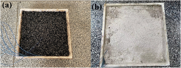 | ||
| Fig. 4 Layered paving compaction and insertion of thermocouples (a) asphalt block and (b) cement block. | ||
After that, the power generation of the TEHS on two kinds of roads was compared and tested. No heat dissipation device was used in the comparative test. To measure the temperature difference of the TEG in each layer, thermocouples were affixed to the upper surface of the heat transfer aluminum plate of each layer (approximately the hot end of the TEG) and the cold end of the TEG to represent the temperature difference of each layer. A VC8246B instrument was used to measure power generation.
2.3 Finite element analysis (FEA)
COMSOL Multiphysics is used to simulate the heat transfer process of the pavement TEHS. The effects of different lengths, widths and thicknesses of the aluminum plate on the heat transfer performance were compared and studied in order to determine the optimum size of the aluminum plate, and the following assumptions are followed in the process of simulation:(1) The whole system is simulated as a transient process. That is, the temperature is constantly changing with time. An analytical function is defined for the transient ambient temperature as follows:26,27
Tambient = Tavg + dT![[thin space (1/6-em)]](https://www.rsc.org/images/entities/i_char_2009.gif) cos[2π(x − 14)/24] cos[2π(x − 14)/24] | (4) |
(2) The ground 300 mm below the soil surface is assumed to have a constant temperature throughout the day, corresponding to the daily average temperature of the site.
(3) The boundary of the whole system is under ideal adiabatic conditions. That is, there is no heat loss in the process of heat conduction.
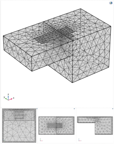
The three-dimensional prototype modeling of the asphalt pavement, soil, and buried TEHS is carried out, the physical properties of the soil and asphalt are defined respectively (Table 1), and the model grid is divided as shown in Fig. 5. The 300 × 300 × 10 mm cuboid simulates the asphalt pavement on the left and the soil on the right, and the multi-layer TEHS is buried under them. The heat transfer coefficient of the road surface is 20 W m−1 K−2 and the solar irradiance is 1000 W m−2. Heat flux generally can be obtained using the following equation:
 | (5) |
| Materials | Properties | ||
|---|---|---|---|
| Thermal conductivity W (m K)−1 | Density (kg m−3) | Heat capacity J (kg K)−1 | |
| Asphalt | 0.8 | 1200 | 900 |
| Soil | 1.59 | 1500 | 800 |
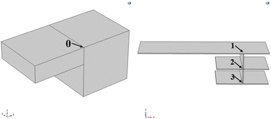
The temperatures of the road surface and heat transfer plates of each layer (a total of three layers) are approximated by points 0, 1, 2, and 3, as shown in Fig. 6, and their temperature variation with time is studied, respectively.
3. Results and discussion
3.1 FEA's results
Aluminum plates with lengths of 150 mm, 250 mm, and 350 mm were selected to compare their heat transfer performance, and a width of 80 mm and thickness of 1.5 mm were fixed. The temperature time point was chosen as 15:00 to draw the heat transfer diagrams of aluminum plates of different lengths. The unified color variation range was 45–55 °C (the darker the color, the higher the temperature), as shown in Fig. 7.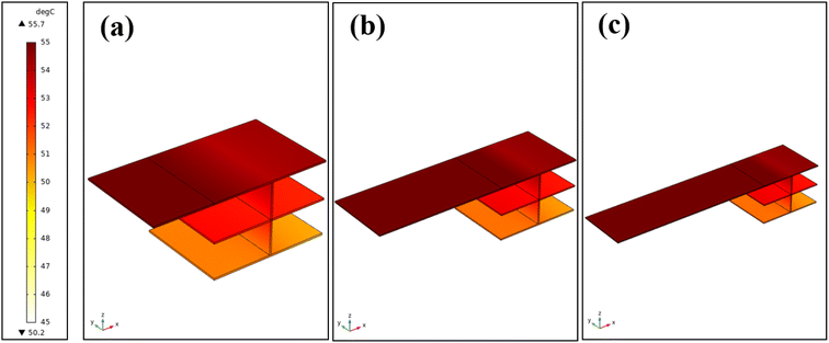 | ||
| Fig. 7 Heat transfer effect diagram of length (a) 150 mm, (b) 250 mm and (c) 350 mm aluminum plate (the leftmost side is the temperature indicator: 45–55 °C). | ||
The results show that when the length of the aluminum plate increases from 150 mm to 250 mm, the temperature of each layer increases by 0.28 °C, 0.55 °C, and 0.41 °C, respectively. However, when it increases from 250 mm to 350 mm, although the temperature of the heat collector plate rises significantly, the heat is not effectively transferred to the heat transfer plate below, so the temperature change of each layer is not apparent, and the data points are basically in a consistent state. To reduce the cost and impact on the road, the aluminum plate with a length of 250 mm is the best choice (Fig. 8).
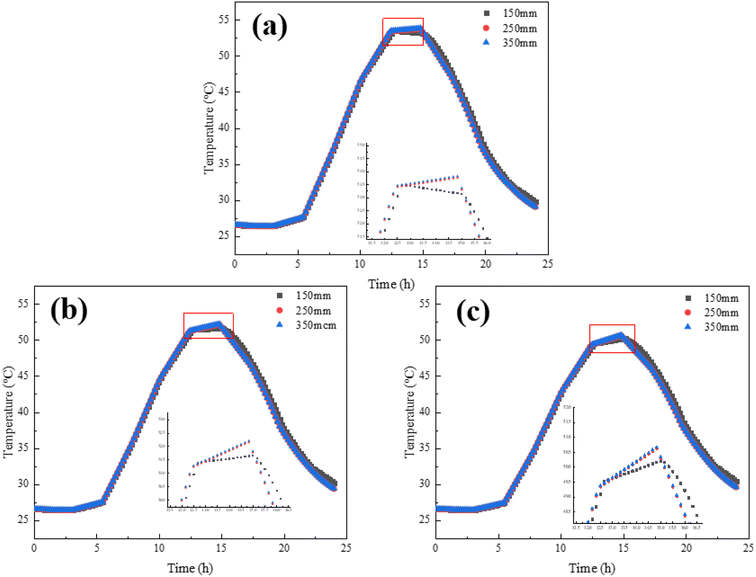 | ||
| Fig. 8 Temperature of the (a) first layer, (b) second layer and (c) third layer with different aluminum plate lengths. | ||
When the length was determined to be 250 mm, aluminum plates with widths of 50 mm, 80 mm, and 100 mm were selected to compare their heat transfer performance, and the thickness was fixed at 1.5 mm, as shown in Fig. 9 below.
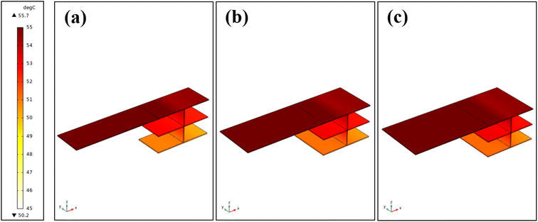 | ||
| Fig. 9 Heat transfer effect diagram of width (a) 50 mm, (b) 80 mm and (c) 100 mm aluminum plate (the leftmost side is the temperature indicator: 45–55 °C). | ||
According to the analysis of data results, when the width of the aluminum plate increases from 50 mm to 80 mm, the temperature of the heat transfer plate of layer 2–3 increases significantly, while the first layer does not increase significantly. However, when the width increases from 80 mm to 100 mm, the temperature of each layer does not increase significantly, and the data points are basically in a consistent state. Considering the cost and power generation efficiency of the system, the best choice for aluminum plate width is 80 mm (Fig. 10).
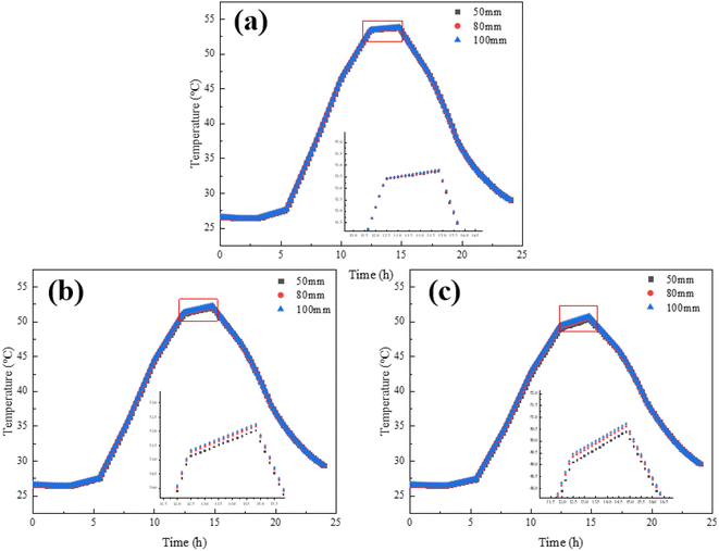 | ||
| Fig. 10 Temperature of the (a) first layer, (b) second layer and (c) third layer with different aluminum plate widths. | ||
When determining the length of 250 mm and width of 80 mm, aluminum plates with thicknesses of 1.5 mm, 3 mm, and 4.5 mm were selected to compare their heat transfer performance, as shown in Fig. 11.
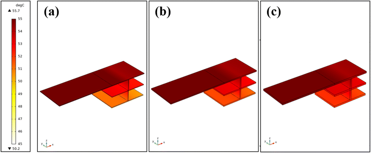 | ||
| Fig. 11 Heat transfer effect diagram of aluminum plates of thickness (a) 1.5 mm, (b) 3.0 mm and (c) 4.5 mm (the leftmost side is the temperature indicator: 45–55 °C). | ||
The temperature of each layer of aluminum plate is shown in Fig. 12. The analysis data show that increasing the thickness of the aluminum plate can significantly improve the heat transfer performance of the third layer, and the temperature increases by 0.8 °C and 0.38 °C, respectively. However, the improvement of the heat transfer performance of the second layer is not apparent, and the temperature only increases by 0.35 °C and 0.16 °C. It even affects the heat transfer performance of the first layer, and the temperature decreases slightly to 0.06 °C and 0.04 °C, respectively. Considering the cost, power generation efficiency and reducing the impact on the road, the thickness of 1.5 mm is the best choice.
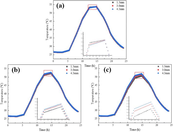 | ||
| Fig. 12 Temperature of the (a) first layer, (b) second layer and (c) third layer with different aluminum plate thicknesses. | ||
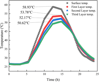
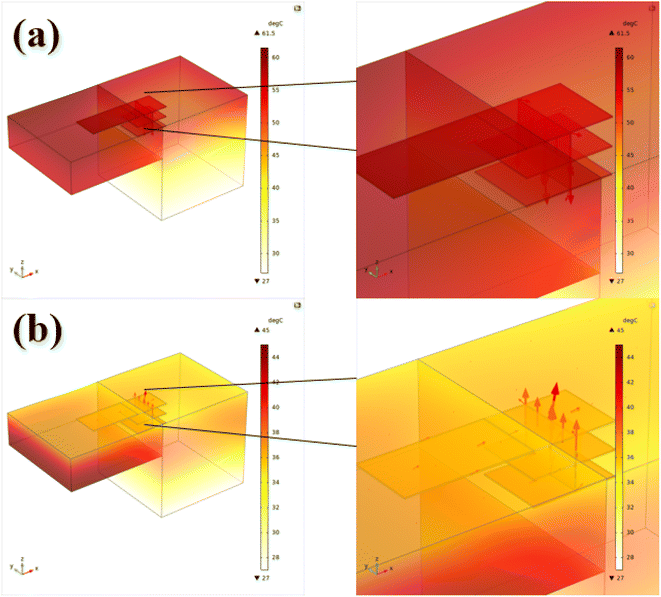
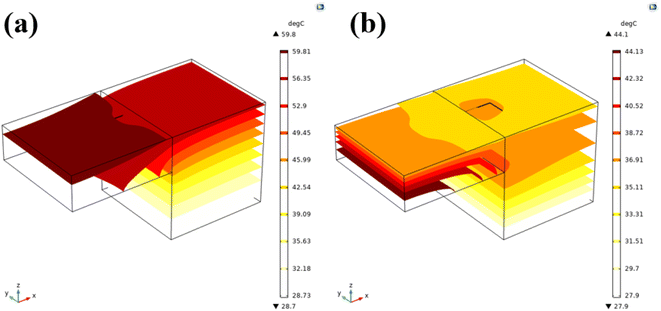
After determining the structure size of the TEHS, the temperature difference between the different layers is shown specifically in Fig. 13, with the difference in temperature between the layers of aluminum plates being around 1–2 °C. As time passes, the temperature of each layer of the aluminum plate is gradually higher than the road surface temperature. Furthermore, the heat transfer diagram and temperature isoline maps of the representative time points at 14:00 and 20:00 were drawn, respectively, as shown in Fig. 14 and 15 (the red arrow represents the direction of conduction heat flux). At 14:00, the road surface absorbs heat and transfers it to the aluminum plate, and the heat direction arrow is vertical downward; at 20:00, the road surface temperature is higher than the ambient temperature, and the heat stored in the depth of the road will be transmitted and diffused upward, the arrow of the direction of heat is vertical upward. This further suggests that roads, which absorb heat during the day and emit heat at night due to temperature differences, exacerbate the urban heat island effect.
3.2 Filed testing results
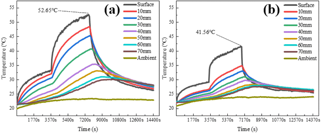
In the indoor test, an iodine tungsten filament lamp (300 W) is used to simulate sunlight heating of the asphalt and cement pavement directly. The temperature intensity is changed by adjusting the distance between the lamp and the roadblock surface. The indoor temperature test is divided into three processes: (1) the lamp is heated at 400 mm (1875 W m−2) from the road surface for 1 hour; (2) the lamp is heated from the road surface at 200 mm (7500 W m−2) for 1 hour; (3) the lamp is turned off to cool down for 2 hours. A total of four hours of temperature testing was carried out (Fig. 16).Fig. 17 shows that the surface temperature of the cement block is much higher than the deep temperature, especially when the lamp is 200 mm away from the cement block (the second stage), and the maximum surface temperature of the cement block is about 10 °C lower than that of the asphalt block. The heat collected on the surface of cement blocks is not effectively transferred down, resulting in the temperature difference between the layers of cement blocks, and the heat collected is smaller than in asphalt blocks. After heating for 2 hours, the lamp was turned off for the cooling test. The cooling rate of the cement block was slower than that of the asphalt block. As time went by, the temperature in the depths of the road is gradually higher than that on the surface.
The outdoor test results can better reflect the temperature gradient inside the road structure in the natural environment. The outdoor test site was selected as a vacant lot at Xi'an University of Architecture and Technology, as shown in Fig. 18. The test time was from 10:00 to 18:00 on May 6 and May 7, 2022, and the temperature changes of the road surface and different depths in the daytime were studied.
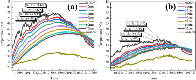
As can be seen from Fig. 19, temperature differences generally exist in road structures. The asphalt road surface temperature reaches a peak of 74.44 °C at 14:07, and the cement road surface temperature reaches a peak of 51.14 °C at 14:50. Besides the surface, the temperature difference of different deep layers of the asphalt road is about 1–3 °C, and the temperature peak is reached at about 14:40 (30 min after the surface temperature peak). In addition to the surface of the cement road, the temperature difference between different deep layers is about 1 °C, and reaches the temperature peak at about 15:15. Whether it is the asphalt block or cement block, the temperature at a depth of 20 mm is only about 1 °C lower than that at a depth of 10 mm, which is much higher than that at other depths. Moreover, the temperature variation range at a depth of 20 mm is relatively tiny as time passes. In conclusion, the optimal embedding depth of the TEHS on the road is 20 mm. As time passed, the road surface temperature was gradually higher than the ambient, and heat began to diffuse. At about 16:40, the deep temperature was gradually higher than the road surface. The indoor and outdoor test results show that because the black surface of the asphalt material absorbs heat easily and has high thermal conductivity, the overall heating rate of the asphalt road is faster, and the temperature gradient in the pavement structure is more prominent. And the temperature of the asphalt pavement is much higher than that of the cement road.
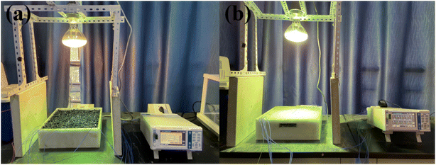
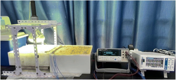
The power generation capacities of asphalt and cement road TEHSs are compared and tested respectively. The indoor testing time is 2 h, as shown in Fig. 20 below.
As shown in Fig. 21, the power generation voltage of the asphalt block is up to 0.15 V, and that of the cement block is up to 0.09 V, which is 0.06 V higher than that of the cement block. The power generation voltage of the asphalt block is higher than that of the cement block, and the temperature difference between the TEG of each layer is also higher than that of the cement block. The data also showed that the asphalt pavement was more suitable for the installation of the TEHS than the cement pavement, and the asphalt pavement was used in subsequent tests.
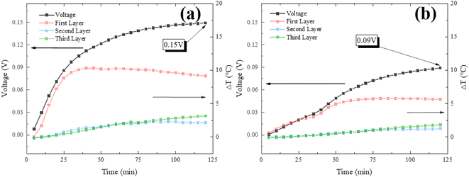 | ||
| Fig. 21 Indoor test of (a) asphalt block and (b) cement block generation voltage and temperature difference of the TEG. | ||
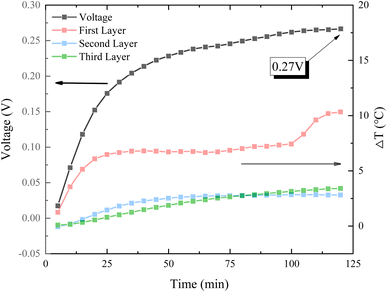
Aluminum fins were attached to the cold end of the TEG for heat dissipation, and its power generation performance was tested indoors and outdoors. In the indoor test, as shown in Fig. 22, the maximum TEHS power generation is 0.27 V, and the power generation is significantly improved by adding heat dissipation components.
The outdoor test was conducted on June 15, 2022. The temperature of the road surface and the heat transfer plates of each layer were also measured.
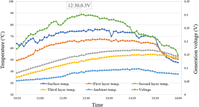
As can be seen from Fig. 23, the voltage generated by the TEHS rises first and then decreases over time, reaching a maximum of 0.3 V at 12:30. The road surface temperature gradually diminishes and is lower than the temperature of each layer, which is also the main reason for the rapid drop of voltage. This is also consistent with the trend of the simulated data results, but the temperature difference between the layers of aluminum panels tested outdoors is large due to the presence of moisture in the soil and other environmental factors in the outdoor tests. In particular, the temperature difference between the first layer and the second layer was around 10 °C.
Table 2 summarizes the temperature of each layer of the aluminum plate, the road surface temperature and the power generation capacity of the system tested by different experimental methods (simulation, indoor, outdoor).
| Experimental method | Maximum temperature (°C) | Power generation (V) | |||
|---|---|---|---|---|---|
| 1st layer | 2nd layer | 3rd layer | Road surface | ||
| Simulation | 53.78 | 52.17 | 50.62 | 58.93 | NA |
| Indoor | 54.87 | 44.55 | 40.34 | 52.65 | 0.27 |
| Outdoor | 67.64 | 58.22 | 54.38 | 76.22 | 0.3 |
In the table, the lower road surface temperature in the indoor test is because the tungsten lamp was 20 mm away from the road surface in the previous road temperature test, while the temperature data for each layer of the aluminum plate were obtained in the power generation test, when the tungsten lamp was almost directly above the road.
It can be seen from the table that the generation voltage of the system did not increase significantly although the aluminum plates of each layer had a high temperature in the outdoor experiments. This is because the temperature of the soil also gradually increased in the outdoor experiment, which led to an increase in the temperature of the cold end of the thermoelectric generator and reduced the temperature difference between the two ends. If the cold end temperature can be effectively prevented from increasing, then more significant power will be collected.
4. Feasibility assessment of the TEHS
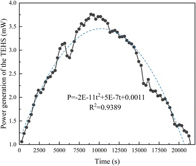
The purpose of this section is to evaluate the ability of the pavement TEHS to collect power. The TEG resistance used in the experiment is about 4 Ω, so the output power can be calculated according to the following formula: | (6) |
The results show that the output power of the TEHS increases at first and then decreases with time, and this relationship can be fitted by the quadratic parabola formula:
| P = −2 × 10⁻¹¹t2 + 5 × 10⁻⁷t + 0.0011 | (7) |
By integrating this function, it can be concluded that aluminum plates with an area of 0.15 m × 0.08 m (heat collection plates used in roads) can collect 73.2 J of the electric quantity within 6 h, so the collected electric quantity per square meter Psm suggested in ref. 23 can be calculated from the following formula:
| Psm = P/At = 73.2/(0.15 × 0.08) = 6100 J m−2 | (8) |
Based on the adequate power generation time of 6 hours per day, the TEHS can collect at least 508 kW h of electric energy per month, which is equivalent to reducing 203.7 kg of CO2 per month, which is equivalent to planting 40 mature trees to absorb a day of CO2 emissions. Based on the Chinese average retail electricity price of 0.075 $ per kW h, each construction of such a thermoelectric conversion road can save at least $464 a year.
In order to better understand the performance of the pavement TEHS, Table 3 presents a comparison of the different types of energy harvesting systems applied to roads. It can be seen that the pavement TEHS has the advantages of low cost, simple structure, easy to use design, etc., while maintaining a high power generation capacity. The results also show that in the case of a limited road area, the design of a multi-layer structural board can significantly improve the power generation and generation efficiency of the system.
| Type | Main structure | Cost ($) | Researcher/company | Electricity generation | Practicability |
|---|---|---|---|---|---|
| Photovoltaic | Hexagonal panel of around 0.4 m2 composed of an electrical layer | NA | Solar Roadways28 | 44 W h per panel | Need for glass pavement with a high friction coefficient and high strength |
| Piezoelectric | The system consists of a piezoelectric layer enclosed between a water proof cover and a flexible backing | NA | Sensitile Systems29 | 25 kW h km−1 | Interference of the cymbals with the pavement performance30 |
| Thermoelectric | Heat dissipation of road water tank | 40 + maintenance cost of water tank | Jiang et al.18 | 3.7 kW h h−1 | High maintenance cost, easy leakage of water tank |
| L-Shaped copper plate | 150 | Tahami et al.23 | 2.9 kW h h−1 | High cost, complex structure | |
| H-Shaped aluminum plate | 52 | Khamil et al.24 | 0.7 kW h h−1 | Limited range of applications | |
| This work | 30 | Weijian et al. | 2.8 kW h h−1 | Low cost, simple structure, easy to use |
5. Economic analysis
The levelized cost of energy (LCOE) is a way of assessing the cost of energy production for a particular system. LCOE is a decisive parameter in the power industry and it can be used to compare the price per unit of electricity generated by non-renewable sources (i.e., fossil fuels) with well-developed renewable sources (such as photovoltaic). This parameter is defined for use in the construction/operation/maintenance (O&M) divided by the number of annual capital spending power generating capacity ($ per kW h).31 | (9) |
Assuming that the service life of the road is 20 years, ignoring operation and maintenance costs, the TEHS CAPEX is about $30, and the electricity generated within 6 hours is 16.94 kW h, the LCOE for TEHS applied on a 10 m wide road is about 0.24 $ per kW h.
According to the current power generation capacity of road TEHSs, it is far from competing with the power grid. Still, from the environmental and ecological point of view, it does not produce any greenhouse gases and substances harmful to the environment in the process of power generation, so it is an entirely new green energy, which is in line with the standard of low-carbon life and is very important to achieve the goal of green earth. With the continuous development of thermoelectric technology, it can be expected that the future pavement TEHSs will be more competitive, with higher efficiency and lower cost, and will become a mainstream power generation system.
6. Conclusions
In this paper, the internal temperature gradients of an asphalt pavement and a cement pavement are studied and compared, respectively. A kind of multi-layer structural pavement TEHS is proposed, which provides more space for the TEG without increasing the road area. The optimal structural size of the aluminum plate is obtained by finite element simulation. After that, the TEHS power generation of different pavements (cement and asphalt) was compared and tested indoors and outdoors, respectively, and the cost calculation was carried out. According to the test results, the following conclusions can be drawn:(1) The finite element simulation results show that the aluminum plate with a length of 250 mm, a width of 80 mm, and thickness of 1.5 mm exhibits the best heat transfer performance.
(2) The temperature and power generation of the asphalt pavement are higher than that of the cement pavement, so the asphalt pavement is more suitable for installing the TEHS.
(3) According to the outdoor test results, the TEHS can collect 73.2 J electricity within 6 h. If this value is converted to a 10 m wide, 1 km long road, 6.1 × 10⁴ kJ equivalent to 16.94 kW h of electricity can be collected 6 hours a day.
4. The electricity collected by the TEHS could be used to power remote areas without requiring millions of dollars in power grids. And the power generation method does not produce CO2, and is a kind of environmentally friendly pollution-free green energy.
5. The pavement TEHS proposed in this paper not only has the advantages of low cost, no maintenance, long life, and easy use, but also achieves considerable power generation, which provides essential guidance for the development and practical application of thermoelectric conversion roads.
Conflicts of interest
There are no conflicts to declare.Acknowledgements
This study was supported by the National Natural Science Foundation of China (Grant Nos. 51578448, 51308447), Natural Science Basic Research Plan in Shaanxi Province of China (Program No. 2017ZDJC-18), Scientific Research Program Funded by the Shaanxi Provincial Education Department (Grant/Award Number: 20JY042), and Natural Science Basic Research Program of Shaanxi for Distinguished Young youths (2021JC-43).References
- J. Webb, D. Hawkey and M. Tingey, Governing cities for sustainable energy: the UK case, Cities, 2016, 54, 28–35 CrossRef.
- A. Alper and O. Oguz, The role of renewable energy consumption in economic growth: evidence from asymmetric causality, Renewable Sustainable Energy Rev., 2016, 60, 953–959 CrossRef.
- I. Dincer and C. Acar, Smart energy systems for a sustainable future, Appl. Energy, 2017, 194, 225–235 CrossRef.
- Z. Y. Wang, R. Wennersten and Q. Sun, Outline of principles for building scenarios – Transition toward more sustainable energy systems, Appl. Energy, 2017, 185, 1890–1898 CrossRef.
- H. Roshani, S. Dessouky, A. Montoya and A. T. Papagiannakis, Energy harvesting from asphalt pavement roadways vehicle-induced stresses: a feasibility study, Appl. Energy, 2016, 182, 210–218 CrossRef.
- V. Bobes-Jesus, P. Pascual-Munoz, D. Castro-Fresno and J. Rodriguez-Hernandez, Asphalt solar collectors: a literature review, Appl. Energy, 2013, 102, 962–970 CrossRef.
- H. Roshani, P. Jagtap, S. Dessouky, A. Montoya and A. T. Papagiannakis, Theoretical and Experimental Evaluation of Two Roadway Piezoelectric-Based Energy Harvesting Prototypes, J. Mater. Civ. Eng., 2018, 30(2), 04017264 CrossRef.
- A. Mohajerani, J. Bakaric and T. Jeffrey-Bailey, The urban heat island effect, its causes, and mitigation, with reference to the thermal properties of asphalt concrete, J. Environ. Manage., 2017, 197, 522–538 CrossRef.
- K. Deilami, M. Kamruzzaman and Y. Liu, Urban heat island effect: a systematic review of spatio-temporal factors, data, methods, and mitigation measures, Int. J. Appl. Earth Obs. Geoinf., 2018, 67, 30–42 Search PubMed.
- C. Niu, X. Tang and X. Li, Review on the Research Progress of Bismuth Telluride Thermoelectric Materials, China Ceram., 2019, 55(01), 1–4+9 CAS.
- N. Jaziri, A. Boughamoura, J. Müller, B. Mezghani, F. Tounsi and M. Ismail, A comprehensive review of Thermoelectric Generators: technologies and common applications, Energy Rep., 2020, 6, 264–287 CrossRef.
- S. LeBlanc, Thermoelectric generators: linking material properties and systems engineering for waste heat recovery applications, Sustainable Mater. Technol., 2014, 1, 26–35 CrossRef.
- T. J. Seebeck, Ueber die magnetische Polarisation der Metalle und Erze durch Temperatur-Differenz, Ann. Phys., 1826, 82(1), 1–20 CrossRef.
- P. G. Lau and R. J. Buist, Calculation of thermoelectric power generation performance using finite element analysis, XVI ICT'97, in Proceedings ICT'97. 16th International Conference on Thermoelectrics (Cat. No. 97TH8291), IEEE, 1997, pp. 563–566 Search PubMed.
- F. J. DiSalvo, Thermoelectric cooling and power generation, Science, 1999, 285(5428), 703–706 CrossRef CAS PubMed.
- J. Mao, Z. Liu, J. Zhou, H. Zhu, Q. Zhang, G. Chen and Z. Ren, Advances in thermoelectrics, Adv. Phys., 2018, 67(2), 69–147 CrossRef.
- C. Gayner and K. K. Kar, Recent advances in thermoelectric materials, Prog. Mater. Sci., 2016, 83, 330–382 CrossRef CAS.
- W. Jiang, D. Yuan, S. Xu, H. Hu, J. Xiao, A. Sha and Y. Huang, Energy harvesting from asphalt pavement using thermoelectric technology, Appl. Energy, 2017, 205, 941–950 CrossRef.
- M. Hasebe, Y. Kamikawa, and S. Meiarashi, Thermoelectric generators using solar thermal energy in heated road pavement, in 2006 25th International conference on thermoelectrics, IEEE, 2006, pp. 697–700 Search PubMed.
- G. Wu, Thermal energy harvesting system to harvest thermal energy across pavement structure, Int. J. Pavement Res. Technol., 2012, 5(5), 311 Search PubMed.
- U. Datta, S. Dessouky and A. Papagiannakis, Harvesting thermoelectric energy from asphalt pavements, Transp. Res. Rec., 2017, 2628(1), 12–22 CrossRef.
- W. Jiang, J. Xiao, D. Yuan, H. Lu, S. Xu and Y. Huang, Design and experiment of thermoelectric asphalt pavements with power-generation and temperature-reduction functions, Energy Build., 2018, 169, 39–47 CrossRef.
- S. A. Tahami, M. Gholikhani, R. Nasouri, S. Dessouky and A. Papagiannakis, Developing a new thermoelectric approach for energy harvesting from asphalt pavements, Appl. Energy, 2019, 238, 786–795 CrossRef.
- K. N. Khamil, M. F. Mohd Sabri, A. Md Yusop, F. A. Z. Mohd Sa'at and A. N. Isa, High cooling performances of H-shape heat sink for thermoelectric energy harvesting system (TEHs) at asphalt pavement, Int. J. Energy Res., 2021, 45(2), 3242–3256 CrossRef CAS.
- W. Jiang, D. Yuan, S. Xu, H. Hu, J. Xiao, A. Sha and Y. Huang, Energy harvesting from asphalt pavement using thermoelectric technology, Appl. Energy, 2017, 205, 941–950 CrossRef.
- F. P. Incropera, D. P. DeWitt, T. L. Bergman and A. S. Lavine, Fundamentals of heat and mass transfer, Wiley, New York, 1996, vol. 6 Search PubMed.
- C. Multiphysics, COMSOL Multiphysics Application Library – Parasol and Solar Irradiation, 2018 Search PubMed.
- J. Brusaw, https://www.solarroadways.com/, accessed July 2021.
- A. Lath, https://www.sensitile.com/projects/powerleap, accessed July 2021.
- D. Vizzari, E. Gennesseaux, S. Lavaud, S. Bouron and E. Chailleux, Pavement energy harvesting technologies: a critical review, RILEM Tech. Lett., 2021, 6, 93–104 CrossRef.
- J. Aldersey-Williams and T. Rubert, Levelised cost of energy–A theoretical justification and critical assessment, Energy Policy, 2019, 124, 169–179 CrossRef.
| This journal is © The Royal Society of Chemistry 2023 |

