
High-performing catalysts for energy-efficient commercial alkaline water electrolysis
Anh Linh
Hoang
a,
Sivakumar
Balakrishnan
b,
Aaron
Hodges
a,
George
Tsekouras
a,
Atheer
Al-Musawi
a,
Klaudia
Wagner
ac,
Chong-Yong
Lee
 ac,
Gerhard F.
Swiegers
*ac and
Gordon G.
Wallace
ac
ac,
Gerhard F.
Swiegers
*ac and
Gordon G.
Wallace
ac
aIntelligent Polymer Research Institute, University of Wollongong, Wollongong 2522, NSW, Australia. E-mail: swiegers@uow.edu.au
bDepartment of Applied Sciences, PNG University of Technology (Unitech), Papua New Guinea
cARC Centre of Excellence for Electromaterials Science, University of Wollongong, Wollongong 2522, NSW, Australia
First published on 30th November 2022
Abstract
‘Green’ hydrogen produced from water electrolysis powered by renewable energy will play a critical role in the future global energy transition to ‘net zero’ carbon emissions. To this end, intensive efforts are needed to improve the energy efficiency with which green hydrogen can be made and thereby reduce its cost. A key required effort in this respect involves developing the most efficient and durable possible catalysts to facilitate the ‘hydrogen evolution reaction’ (HER) at the cathode and the ‘oxygen evolution reaction’ (OER) at the anode in alkaline water electrolysers. Most work in this regard has focused on improving the activity of catalysts at or around a standard current density of 10 mA cm−2 for both the HER and OER. However, to be practically useful, electrocatalysts must operate efficiently at commercial current densities, which are typically much higher; for example, commercial alkaline water electrolysers routinely operate at current densities of 200–700 mA cm−2. Reviews of such electrocatalysts and their suitability for commercial-scale water electrolysis are rarely reported. This work presents an overview of recent progress in this respect. The most energy efficient and durable electrocatalysts for the HER, the OER, and for overall water splitting, are identified, discussed, and prioritized with a view towards enhancing commercial alkaline water electrolysis. The major challenges involved in their preparation and operation, as well as potential avenues for further performance improvements as reliable, robust electrocatalysts for commercial alkaline electrolysis are also highlighted. The latest work on new technology development in alkaline water splitting is also presented. The high-performing catalysts that are most likely to accelerate the prospects of green hydrogen are listed in a comparative table. A discussion of future directions in this emerging field is also provided.
1. Introduction
The recent COP26 meeting1 has sparked much interest in the global community about the need to attain ‘net zero’ carbon emissions by 2050. ‘Green’ hydrogen, which is hydrogen produced from water using electrolysis powered by renewable electricity, is poised to play a key role in this energy transition as it offers the only viable means of decarbonizing a host of ‘hard-to-abate’ industries, including long-haul transport, shipping, aviation, and steel, amongst others.The production of green hydrogen is currently an active field of research that has been explored in detail in the scientific literature. While numerous water electrolysers have been developed over the last 200 years, hydrogen produced by electrolysis still comprises only a tiny fraction (<5%) of the worldwide production of hydrogen due to its inefficient energy consumption and high cost.2 Of the different methods of producing hydrogen by electrolysis, alkaline electrolysis is one of the most promising; it offers a mature technology that combines a capacity for high production volumes with the lowest-available production costs.2
Given the need to reduce the cost of producing green hydrogen, intensive efforts are being made to develop innovative processes that increase the efficiency of alkaline electrolysis. New advances include the development of membraneless alkaline electrolysis systems that do not require an inter-electrode separator.3 Electrolysis cells comprising two porous gas diffusion electrodes that use capillary effects to directly extract the generated gases through the electrodes without visible bubble formation have also been developed.3–7 Most recently, an innovative ‘capillary-fed’ alkaline electrolysis cell, which offers the promise of a breakthrough energy efficiency, has been described.8 These efforts necessarily involve developing high-performing electrocatalysts for the oxygen-evolution reaction (OER) (at the anode in a water electrolysis cell) and the hydrogen-evolution reaction (HER) (at the cathode in a water electrolysis cell). Improving catalytic performance offers a viable means of making the entire process more energy efficient.
An efficient catalyst should provide high catalytic activity (i.e. large current density at low overpotential) and long-term durability in operation. Recently, platinum group metal (PGM) catalysts had the highest activity for HER and OER, respectively.9 However, their scarcity and high cost have hindered application in large-scale deployment.10,11 Therefore, the exploration of cheap, robust, and earth-abundant electrocatalysts has received much attention. Various earth-abundant materials including transition-metal based compounds, oxides and non-oxide catalysts have been reported as promising electrocatalysts for energy-efficient alkaline water electrolysis.12–14
From an industrial point of view, it is essential to develop high-performing, robust electrocatalysts that can sustain high current densities (for example, 200–700 mA cm−2) to end-of-life in water electrolyser systems without significant electrochemical degradation.9 Despite the efforts directed to electrocatalyst development, the strict requirement for durability in commercial applications (10 years or more) has largely been overlooked in previous studies.
This review is intended to inspire further scientific advancements in alkaline water electrolysis. The development of OER electrocatalysts, which has been a bottleneck in the water splitting process, is emphasised, with particular attention to those catalysts capable of operating steadily at high current densities. The development of architectures and designs of water electrolysis system as well as related economic aspects have been well reviewed15 in the past and are not discussed in detail in this review.
The work commences with an exposition of the fundamentals of electrochemical water electrolysis. It then reviews and concentrates on high-performing electrocatalysts that: (i) overcome the high energy barriers involved in the HER and OER, to thereby: (ii) improve the kinetics and long-term stability of the cathode and anode electrodes, as well as (iii) potentially providing high catalytic performance and efficiency suitable for commercial alkaline water electrolysis. The review further extends to an exploration of the production of ‘green hydrogen’, which will be a turning point in human history if the goal of net zero emission is achieved.
The work concludes with a ranked tabulation of what seem, to the authors, to be the most promising and high performing HER, OER, and overall water-splitting systems available today for alkaline electrolysis. We recommend that researchers seeking to accelerate the prospects of green hydrogen, focus on further studies of these electrocatalysts.
2. Mechanism of the electrochemical hydrogen evolution reaction (HER) and the oxygen evolution reaction (OER) in alkaline media
Water electrolysis is the process whereby water is decomposed into hydrogen (H2) and oxygen (O2) by applying an electrical current within an electrochemical cell, known as an electrolysis cell or an electrolyser cell. Typically, an electrolysis cell consists of an anode, a cathode, a liquid electrolyte and an ion-permeable, gas-impermeable “separator” between the electrodes (Fig. 1). When a direct current is passed through the cell, redox reactions occur at the electrodes. Hydrogen is produced at the cathode and oxygen is produced at the anode, usually in the form of gas bubbles within the liquid electrolyte. The electrolyte provides a pathway for ion movement between the two electrodes; the ions pass through the separator. Beyond ion conduction, the main task of the separator is to keep the gas bubbles produced at each electrode from mixing with each other since a hydrogen stream containing >4.6% oxygen, or an oxygen stream containing >3.8% hydrogen, comprises an explosive mixture (at 80 °C, which is a common operating temperature for an electrolyser). | ||
| Fig. 1 Schematic diagram of an electrolysis cell, or an electrolyser cell. | ||
The chemical reactions that occur at the cathode and anode in alkaline condition are:
| Anode: 4OH− → 2H2O + O2 + 4e−E0 = 0.40 V | (1) |
| Cathode: 2H2O + 2e− → H2 + 2OH−E0 = −0.83 V | (2) |
| Overall: 2H2O → 2H2 + O2E0 = 1.23 V | (3) |
In order to split water into hydrogen and oxygen, the voltage applied to the cell must generally be significantly higher than the standard equilibrium potential for water electrolysis (E0 1.23 V). The additional energy input is known as the overpotential.
The OER that occurs at the anode involves a 4-electron transfer to produce a molecule of O2, as shown in eqn (1). The HER at the cathode involves a 2-electron transfer to form a molecule of H2 as depicted in eqn (2). A much higher overpotential is required for the OER than for the HER because it has a higher kinetic barrier resulting in a higher energy consumption. The anodic reaction therefore poses the main challenge to improving the energy efficiency of electrolysers.16 The development of high performing electrocatalyst for the OER is therefore more critical than for the HER. Understanding of the electrochemical reaction process is, however, crucial for designing efficient catalysts, whether they facilitate the OER or the HER. Several recent works have examined and reviewed the mechanisms of the HER and OER process.17–21
2.1 Mechanism of the hydrogen evolution reaction
The HER at the cathode is one of the most studied processes in electrochemistry. The HER is described by the Volmer–Heyrovsky–Tafel reaction mechanism.10 In alkaline solution, hydrogen is generated by the electrochemical reduction of water, in the half-reaction in eqn (2).The reaction pathway in alkaline solution is: (M = active surface site)
| M + H2O + e− → MHads + OH− Volmer step | (4) |
| MHads + H2O + e− → M + OH− + H2 Heyrovsky step | (5) |
| 2MHads → 2M + H2 Tafel step | (6) |
The symbol MHads denotes hydrogen atoms adsorbed on the electrode surface. The first step involves the adsorption of hydrogen atoms on the electrode surface (Volmer step) through the reduction of water in alkaline solution (eqn (4)). H2 is then formed through desorption by either the Heyrovsky step or the Tafel step. The Heyrovsky reaction involves the direct bonding of a hydrogen atom with a second water molecule in alkaline media (eqn (5)). The Tafel reaction involves, effectively, the recombination of two hydrogen atoms adsorbed on the surface (eqn (6)).22
The steps of adsorption (Volmer step) or desorption (Heyrovsky step or Tafel step) can be rate determining depending on the electrode surface. If the bond between the hydrogen atom and the catalytic surface is too strong, the second step is rate limiting. If that bond is too weak, the first step is rate limiting.23,24
2.2 Mechanism of the oxygen evolution reaction
The OER is the most important process in water electrolysis. Its mechanism, which involves a 4-electron process, is more complex than the HER, which is a 2-electron process, and includes many different intermediate states in the reaction. Several kinds of activation steps may determine the rate of the OER. Therefore, the mechanism may not always be fully understood and can depend strongly on the catalyst used.25 Generally, the OER in alkaline conditions can be described in the following steps as shown below.| M + OH− → MOHads + e− | (7) |
| MOHads + OH− → MOads + H2O + e− | (8) |
| 2MOads → 2M + O2 | (9) |
| MOads + OH− → MOOHads + e− | (10) |
| MOOHads + OH− → M + O2 + H2O + e− | (11) |
The M-bound OH−, O2−, and OOH− in the above steps are the reaction intermediates adsorbed on the active site of catalyst surface (M = active surface site).9 A number of reaction pathways have been proposed in the literature with the most widely accepted involving the same intermediates of M–OH and M–O.26,27 At the first step, an OH− species is adsorbed at the active surface site (eqn (7)), whereafter it is transformed to a MOads species by oxidation of the metal site (eqn (8)). The major differences in mechanism likely revolve around the mechanism to produce oxygen. Two different approaches have been considered for the formation of oxygen from a MOads intermediate.16 One approach, described early on by Bockris, involves an electrochemical oxide path (eqn (7)–(9)) as oxygen is formed directly by combination of two MOads species.28 An alternative mechanism has been reported by Yeager and colleagues,29,30 wherein the MOads species reacts with another OH− ion (eqn (10)) resulting in an oxy-hydroxide MOOHads intermediate that is then oxidized to release O2 (eqn (11)) in final step.31
3. General measures for evaluating catalytic performance
3.1 Overpotential
The cell overpotential is defined as the difference between the experimentally-required cell potential to drive an electrochemical reaction at a certain rate and its thermodynamically-expected cell potential at that rate.Overpotential is one of the most important quantities to consider when evaluating catalytic performance in water electrolysis.32 It is directly related to the energy efficiency of the water electrolysis cell since a small overpotential results in a higher electrochemical conversion efficiency. It is experimentally determined by measuring the potential at which a particular current density is produced. This is usually done using linear sweep voltammetry (LSV), which is typically performed under steady-state conditions and at low scan rates (e.g., 2 mV s−1, 5 mV s−1 and 10 mV s−1) to reduce capacitive current contributions.33 The overpotential required to produce each current density can be considered to ‘activate’ the reaction, with the activation step then comprising the sum of the mass transfer and the charge transfer resistance. In order to precisely compare catalytic activities, the activation overpotential should be corrected by iR-compensation (eqn (12)), where i is the current flow in the circuit and Rs is the sum of the series resistances: namely, mass transfer, charger transfer resistance, etc.
| Ecorrected = Emeasured − iRs | (12) |
Generally, the overpotential required to achieve a current density of 10 mA cm−2 corresponds to 10% efficiency in the solar-conversion within a photoelectrochemical water splitting device. For this reason, 10 mA cm−2 has been widely used as a benchmark for evaluating catalyst performance.34–36 However, to meet industrial standards for practical water splitting, electrocatalysts must afford commercial current densities, which typically operate at much higher currents; for example, commercial alkaline water electrolysers routinely operate at current densities of 200–700 mA cm−2 which may require cell potentials of 1.8–2.4 V.9 Such electrocatalysts must also demonstrate high durability, with lifetimes of 90![[thin space (1/6-em)]](https://www.rsc.org/images/entities/char_2009.gif) 000 hours, or around 10 years, typically required.
000 hours, or around 10 years, typically required.
It is a significant challenge to develop high performing water electrolysis electrocatalysts that exhibit the necessary long-term stability at high current densities (200–700 mA cm−2). For this review, catalyst performances has been judged by comparisons of the overpotential required to produce a benchmark current density of 10 mA cm−2 and a commercial operating current density in the range 200–700 mA cm−2.
3.2 Electrode
There have been extensive efforts to develop catalysts that are highly active, cost-effective, and that display stable long-term performance under harsh working conditions. High performing catalysts are almost always synthesized without supporting structures, such as in the form of nanoparticle, nanosheet, core–shell nanostructure, and other ingenious nanostructures.37–42 However, in industrial practice, high performing catalyst development should be integrated with electrode design to exhibit long-term stability.The design of electrodes/supports play a critical role in increasing the efficiency of both the HER and OER in alkaline water electrolysis. Based on the development of electrode structure, electrode design can be divided into two categories: flat surface electrodes (2D) and 3D electrodes. Both electrode designs have their own advantages and limitations.
Flat surface electrodes, such as Cu/Ti foil, glassy carbon (GC) and 2D ultrathin sheets provide good mechanical stability but they limit the catalyst loading on the substrate, inhibit mass and charge transport, and thereby diminish the overal catalytic activity.43,44 As a result, these electrodes generally produce low current densities and require high overpotentials for both HER and OER.
To address these challenges, 3D electrodes supported by metal foams (e.g. Ni, Fe, and Cu), stainless steel meshes/mats, carbon cloth, carbon paper, carbon fibers and carbon nanotubes have been widely employed to improve the catalytically active surface area and mass transport properties, as well as enhance gas diffusivity. Nickel foam (NF) has been commonly used as an ideal support for HER/OER catalyst due to its high electrical conductivity. It is true that the porous structure of NF can facilitate the electrolyte transfer and promote generated gas bubbles release during water electrolysis.35,45 However, an inappropriate fabrication method may affect the interfacial adhesion between the catalyst and substrate, resulting in poor stability. Hydrothermal, solvothermal, and electrodeposition approaches have been widely used to synthesize nanostructure electrodes grown on NF substrate.46–48
3.3 Electrolyte
The electrolyte provides the ionic conduction pathway between the electrodes. Different electrolytes influence the performance of the electrodes and the electrolysis reaction in general. Liquid alkaline solution of sodium and potassium hydroxide with a typical concentration of 20–40% have been widely used as the electrolyte in alkaline electrolysis due to its high conductivity.49 However, aqueous solution of KOH are preferred over NaOH because of their higher specific conductivity.50 The maximum conductivity of KOH aqueous solutions is obtained at 30 wt%. This concentration is commonly used in modern alkaline electrolysers.3.4 Tafel slope and exchange current density
A Tafel plot is produced by graphing the overpotential as a function of the logarithm of the current density (from a corresponding LSV curve). The slope of the linear region of a Tafel plot is known as the Tafel slope. The Tafel slope is normally determined at low overpotentials using eqn (13):| η = blogj + a (Tafel equation) | (13) |
A Tafel plot depicts the additional potential required to increase the catalytic current by an order of magnitude, with typical units of mV per decade. A small Tafel slope corresponds to a large change in the electrocatalytic current density. Therefore, low Tafel slopes are desirable when developing catalysts with high performance in water electrolysers.
The exchange current density is defined as the equilibrium potential at which the anodic and cathodic currents are equal. It is another key parameter with which to evaluate catalytic efficiency. The exchange current density reflects the intrinsic activity of charge transfer between the electrode and electrolyte. It can be determined by extrapolating the linear part of a Tafel plot to the x-axis. The point of intersection is the exchange current density.
It should be noted that the exchange current density varies significantly with the catalyst used and the experimental temperature. The exchange current density is also considered to be proportional to the (electro)catalytically active surface area (ECSA). The larger the exchange current density, the larger the surface area and the faster the rate of electron transfer.
Given that a high performing catalyst will ideally exhibit a small overpotential, a low Tafel slope and a large exchange current density, this combination of metrics may appear to offer an ideal means of appraising the electrocatalytic activity of catalysts.
However, these parameters are not independent of each other and this may complicate the analysis. For instance, two HER electrocatalysts with different Tafel slopes could require the same overpotential to produce a current density of 10 mA cm−2. In such a case, the Tafel slope does not identify the best catalyst, at least at 10 mA cm−2.
The Tafel slope may, under certain conditions, provide some valuable insights into the possible reaction mechanism.36 However, it is difficult to elucidate the operating mechanism for multi-step electron transfer processes including many possible intermediates that may change with applied potential, such as OER.32,51 In most cases, additional experiments are required in combination with Tafel slope to identify the catalytic mechanism and materials.52,53 Nevertheless, a better electrocatalyst will always shows a smaller overpotential at the current density of interest.
3.5 Turnover frequency
The overpotential required to produce a current density of interest is normally used for activity comparisons of catalysts. However, different catalyst mass loadings may lead to changes in active site density and active surface area. It is generally challenging to evaluate the intrinsic activity of different catalysts when different mass loadings have been used. To normalise for such variations, the ‘turnover frequency’ (TOF) is used as a measure of the intrinsic site activity of a catalyst.54,55 TOF is defined as the number of product molecules generated per active site per unit time (eqn (14)):56–58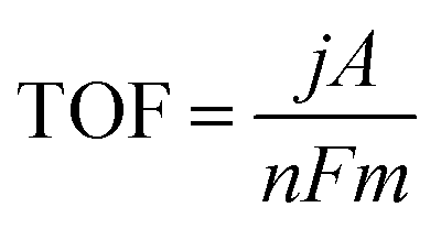 | (14) |
485 C mol−1) indicating the number of moles of electron consumed to produce one mole of product, and m is the number of moles of active sites.
The main drawback of the TOF metric is finding a precise way to calculate the total number of active sites accurately because this may not be proportional to the mass loading due to morphology variations in the catalyst. To estimate the number of active sites, the total surface area or electrochemically active surface area (ECSA) may also be employed.23
3.6 Durability
The long-term operational stability, or durability, of a catalyst is one of the most important properties from the point of view of high performance. A catalyst cannot be considered high performing if it only has a short operational lifetime.The durability of a catalyst is best evaluated by extended testing under an applied overpotential (chronoamperometry test) or at a given current density (chronopotentiometry test), and then measuring the change in overpotential or current density over time.
Indications of likely durability can also be assessed by considering the change in repeated LSV curves at current densities of interest. Such tests may be carried out before and after the longer-term stability tests noted above. If a catalyst loses its activity quickly, an increase in overpotential or decrease in current density will become apparent.
Generally, a fixed current density of 10 mA cm−2 has been employed by researchers to evaluate catalyst stability. However, this is practically inadequate, especially given the fact that many catalysts degrade slowly over time due to electrochemical corrosion.59–63 For industrial applications, much higher current densities, such as 200 mA cm−2, 500 mA cm−2, or even 1000 mA cm−2 have recently been used to test catalyst durability. Long term testing duration of 10–2000 h have been considered as benchmarks for comparison.64–67
4. Overview of hydrogen-evolving catalysts in alkaline media
4.1 Noble metal catalysts
Several studies over the years have focused on developing efficient alkaline catalysts for the HER. Pt and Pt-group metals (i.e., noble metals) have been most widely studied; these have generally demonstrated very low overpotentials for the HER process. However, the expensive nature and the scarcity of Pt group metals (PGMs) have hindered their applications in large-scale industrial applications.10,11 Additionally, noble-metal catalysts also suffer from scarcity (high cost) and may display poor stability in alkaline electrolysis systems, especially if they become contaminated with organic materials that bind irreversibly.68Many studies have demonstrated that Pt exhibits lower HER activity in alkaline than in acid media. It also displays more rapid decreases in activity over long term measurements.51,69–71 Such losses in activity are largely due to surface contamination from trace organic materials in the cells used in the measurements.72,73
As the most popular commercial HER catalyst, Pt typically displays an excellent HER activity with a low Tafel slope (30 mV dec−1) in alkaline electrolytes.74,75 A current density of 10 mA cm−2 can be achieved at a low overpotential of 36 mV in 1 M NaOH at room temperature. Higher current densities of 50 mA cm−2 and 100 mA cm−2 may be achieved at 81 mV and 92 mV, respectively.76 In order to increase performance, higher loadings of Pt are required. In the case of Pt nanoparticles, agglomeration may then occur, decreasing the active surface area and impeding the catalytic performance.77,78
This may be counteracted by using carbon support materials, such as carbon black, carbon nanotubes, carbon nanofibers or graphene, which not only decrease the amount of Pt needed, but increase its electrocatalytic activity.79 For example, Chang et al.80 reported that a commercial Pt/C, combined with 5% Nafion solution in a mixture of water and ethanol (% v:% v = 1:1) loaded on carbon fiber paper, delivered 20 mA cm−2 at an overpotential of 45 mV in 1 M KOH electrolyte. Wang et al.81 noted that the activity of Pt/C strongly depends on the OH− concentration of alkaline electrolyte, such that the Tafel slope declines from 180 mV dec−1 in 0.01 M KOH electrolyte to 94 mV dec−1 in 0.1 M KOH and only around 30 mV dec−1 in 1 M KOH.
Combining Pt with other metals may also be used to realize highly active and low-cost catalysts. For instance, the Pt3Ni alloy introduced by Chen et al.82 showed impressive HER activity that was 22-times higher than that of commercially available Pt/C.
Efforts have also focused on developing new catalysts for alkaline media that exhibit improved energy efficiency and narrow the gap in overpotential for Pt in alkaline vs. acidic electrolytes. A plausible approach has been to combine Pt with transition metal hydroxides that enhance the HER activity.
Subbaraman et al.74 successfully synthesized ultrathin Ni(OH)2 nanoclusters (height 0.7 nm, width: 8 to 10 nm) on modified, pristine Pt(111) single crystal surfaces by electrochemical deposition and studied the effect of Ni(OH)2 on HER activity. Scanning tunneling microscopy (STM) (Fig. 2(a–d)) shows how the morphology changes from atomic structures of Pt(111) to Ni(OH)2 nanocluster-modified Pt(111)/Pt-islands. The presence of Pt islands and Ni(OH)2 nanoclusters enhanced the actives sites thereby accelerating HER catalysis (Fig. 2(e)). The authors expressed the opinion that Ni(OH)2 clusters played a promoting role in water adsorption by accelerating interaction of O atoms with Ni(OH)2 and H atoms with Pt at the boundary between Ni(OH)2 and Pt domains. They then further assisted water dissociation when two Hads atoms, adsorbed on the Pt surface, recombined into H2 molecules during the H2 desorption stage. In addition, the presence of Li+ cation may have further increased the interaction between hydrated metal cations and adsorbed OHads species in the alkaline environments, resulting in an enhancement in the concentration of OHad clusters at the interface.83 The resulting hybrid material displayed a performance that was comparable to the activity of Pt in acidic solution.
 | ||
| Fig. 2 (a–d) STM images (60 nm by 60 nm) and CV traces for (a) Pt(111), (b) Pt(111) with 2D Pt islands, (c) Pt(111) modified with 3D Ni(OH)2 clusters, (d) Ni(OH)2/Pt-islands/Pt(111) surface. Clusters of Ni(OH)2 in the STM images appear ellipsoidal with particle sizes between 4 and 12 nm. (e) Comparison of HER activities with Pt(111) as the substrate, with incremental HER activity in sequence: the bare Pt(111) (black line), Pt(111)/Ni(OH)2 (blue line), Pt(111)/Ni(OH)2/Pt-islands (green line), Pt(111)/Ni(OH)2/Pt-islands/10−3 M Li+ (red line) and Pt(111) in 0.1 M HClO4 (dashed line), electrolyte 0.1 M KOH, sweep rate of 50 mV s−1. (f) Schematic representation of the HER process on β-Ni(OH)2/Pt electrode for Volmer and Heyrovsky steps. Images (a–e) reproduced from ref. 74 with permission from the American Association for the Advancement of Science, Copyright ©2011. Reproduced from ref. 84 with permission from The American Chemical Society, Copyright© 2017. | ||
In separate work, Yu et al.84 also proved that the HER activity of pristine Pt in alkaline solution was higher when α-Ni(OH)2 or β-Ni(OH)2 nanostructures were incorporated. A lower overpotential and smaller Tafel slope was observed with a β-Ni(OH)2/Pt electrode due to the stronger interactions between the β-Ni(OH)2 clusters and the Pt substrate with greater water dissociation ability. The proposed HER mechanism of the β-Ni(OH)2/Pt electrode in alkaline media is shown in Fig. 2(f). It involved a Volmer step in which water molecules dissociated into Hads species on the Ni(OH)2 lattice, followed by a Heyrovsky step in which Hads species combined with H atoms to form H2 molecules on the Pt surface.
Other research85 reported on the enhancement of catalytic stability by growing ultrathin Pt nanowires on 2-D Ni(OH)2 nanosheets. Although this method contributed to an increase in the activity of the Pt group catalysts in alkaline media, it still had a limitation in practical applications due to its complex synthesis method and poor stability in long-term operation.
Ruthenium (Ru) is a potential alternative to Pt as the strength of the Ru–H bond is similar to that of Pt–H (∼65 kcal mol−1). This may enable Ru-based catalysts to exhibit comparable HER activities to Pt.86–88
Baek et al.88 prepared Ru@C2N catalyst by dispersing Ru nanoparticles within a nitrogenated, holey, 2-D carbon structure. The C2N layer frameworks had nano sized holes, which provided large surface areas, anchoring sites, and conductive platforms for the Ru nanoparticles. The Ru nanoparticles nucleated and grew, producing an abundance of uniformly distributed coordination sites. In 1 M KOH solution, the as-prepared Ru@C2N required an overpotential of only 17 mV to produce a current density of 10 mA cm−2. To generate 20 mA cm−2, an overpotential of 35.5 mV was required; this was lower than the overpotential of commercial Pt/C under the same conditions.83,84 It also exhibited a higher TOF (0.76 H2 s−1 at 25 mV; 1.66 H2 s−1 at 50 mV) than commercial Pt/C (0.47 H2 s−1 at 25 mV; 0.95 H2 s−1 at 50 mV) and excellent stability in 1 M KOH solution with negligible degradation.
Noble metal-based catalysts may, potentially, not be ideal for large scale industrial use due to high material cost and the scarcity of their sources. Therefore, development of non-noble metal catalyst for the HER have seen increasing commercial and research activities.
4.2 Earth-abundant (non-noble) metal catalysts
Raj et al.92–94 investigated the HER activity of several Ni-based binary composites such as Ni–Mo, Ni–Zn, Ni–Co, Ni–W, Ni–Cr and Ni–Fe, coated on a steel substrate by electrodeposition. They found that Ni–Mo was the best electrocatalyst with long-term stability and resistance to corrosion.91 They also showed that an optimized Ni-ternary composite of Ni–Mo–Fe, coated on a mild steel substrate, exhibited a steady current density of 300 mA cm−2 at an overpotential of 187 mV at 80 °C for over 1500 h of electrolysis. This is 300 mV lower in the cathodic overpotential when compared with commercial mild steel plate under the same operating condition.
From an industrial point of view, catalyst that can be easily prepared by coating onto a conductive substrate may be preferred. For example, McKone et al.95 developed a method to coat Ni–Mo nano powders onto various substrates with different loadings. Firstly, powders were prepared by slow decomposition of mixed Ni and Mo salts into mixed Ni–Mo oxides/hydroxides, followed by annealing at high temperature under an atmosphere of 5% H2 and 95% N2. The resulting powders were then suspended in common solvents and cast onto the substrate, followed by annealing at 400–450 °C under the above gas mixture, to improve the adhesion and conductivity of the catalytic layer.
In 2 M KOH solution, with a very low loading of 1.0 mg cm−2, the Ni–Mo nano powder electrode required an overpotential of 70 mV to generate 20 mA cm−2. With a higher loading of 13.4 mg cm−2, 130 mA cm−2 was produced at an overpotential of 100 mV. No degradation was observed at 20 mA cm−2 after testing for 100 h in alkaline solution.
The optimum Mo loading in Ni–Mo alloys has also been examined in electrocatalytic HER. In their patent, Brown et al.96 described a method to prepare Ni–Mo on a metal substrate. For 30 atom% of Mo in the Ni–Mo, by optimizing the Ni–Mo electrode loading to 20 mg cm−2, a current density of 1000 mA cm−2 could be achieved at an overpotential of only 80 mV at 70 °C in 30 wt% aqueous KOH solution.
In separate work, Xiao and colleagues found an optimal loading for a Ni–Mo electrode to be 40 mg cm−2. The electrode generated a current density of 400 mA cm−2 at 110 mV overpotential in 1 M KOH electrolyte at 40 °C.97 However, the authors also noted that a thick electrode may contribute to voltage drops during stability tests.
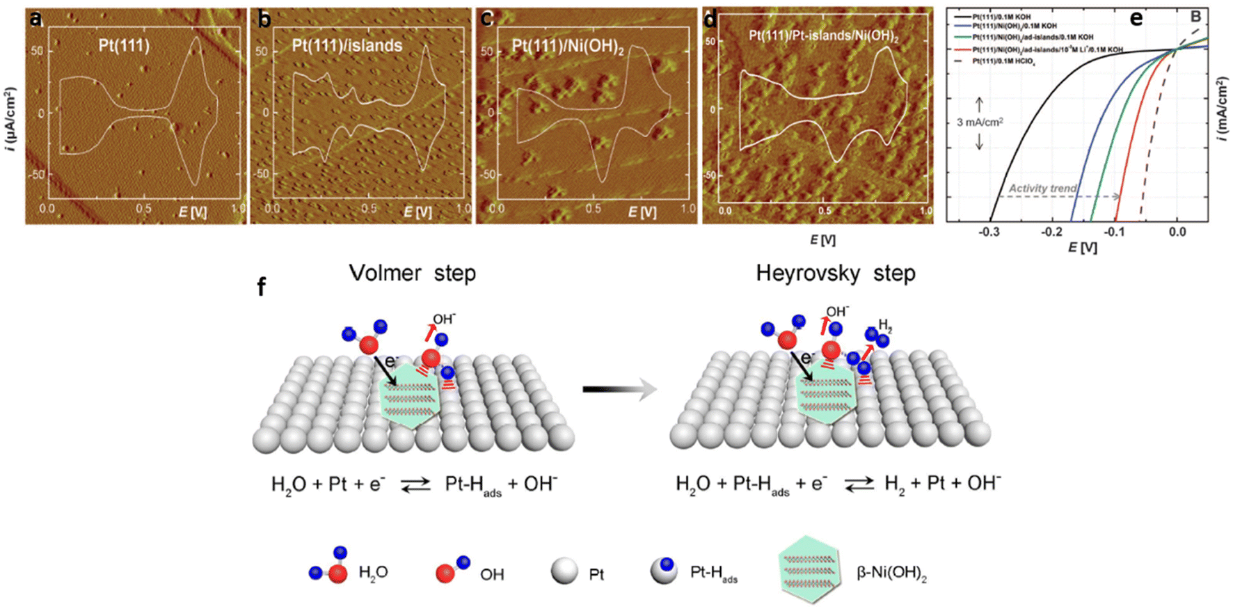
Zhang et al.66 reported a high performing MoNi4 electrocatalyst supported by MoO2 cuboids on nickel foam (MoNi4/MoO2@Ni). The catalyst was prepared by growing NiMoO4 on nickel foam via a hydrothermal reaction, followed by a calcining process in a H2/Ar (v/v, 5/95) atmosphere at 500 °C for 2 h (Fig. 3(a–g)). A substantially enhanced HER activity with a low Tafel slope of 30 mV dec−1 in 1 M KOH electrolyte (Fig. 3(i)) was observed. In addition, MoNi4/MoO2@Ni delivered current densities of 10 mA cm−2, 200 mA cm−2, and 500 mA cm−2 at overpotentials of 15 mV, 44 mV, and 65 mV, respectively (Fig. 3(h)). Fig. 3(j) and (k) display the energy barrier of the Volmer step (H2O dissociation) and Tafel step (formation of adsorbed hydrogen) from DFT calculations. The free energy of MoNi4 for the Volmer step was lower than on Pt (0.39 eV vs. 0.44 eV).75 The results demonstrated a largely decreased energy barrier for both the Volmer and Tafel step for MoNi4 electrocatalysis. In addition, to understand the origin of the high HER activity, the authors measured the HER onset potential of pure MoO2 nanosheets and MoNi4 supported by MoO2 cuboids on carbon cloth in 1 M KOH. They concluded that the excellent HER performance of MoNi4/MoO2@Ni derived from the MoNi4 nanoparticles rather than from supporting MoO2 cuboids. A series of HER stability measurements at different current densities (10 mA cm−2, 100 mA cm−2, and 200 mA cm−2) were performed over a total of 30 h but no change in the catalyst structure was observed, indicating that the structure of the MoNi4 electrocatalyst was robust.
 | ||
| Fig. 3 (a–c) Typical SEM and (d–f) HRTEM images of MoNi4/MoO2@Ni; (g) corresponding elemental mapping images of MoNi4 electrocatalyst and MoO2 cuboids. The inset image in (d) is the related selected-area electron diffraction pattern of the MoNi4 electrocatalyst and the MoO2 cuboids. Scale bars, (a) 20 μm; (b) 1 μm; (c) 100 nm; (d–f) 2 nm; inset in (d) 11 nm; (g) 20 nm; (h) LSV curves of various catalysts as indicated, electrolyte: 1 M KOH, scan rate: 1 mV s−1; (i) Tafel plots of the MoO4 electrocatalyst supported by the MoO2 cuboids, pure Ni nanosheets, and MoO2 cuboids on the nickel foam; (j) calculated adsorption free energy diagram for the Volmer step and (k) Calculated adsorption free energy diagram for the Tafel step of various catalysts as indicated. Reproduced from ref. 66 with permission. Copyright ©2017, The Authors, some rights reserved; exclusive licensee Springer Nature. Distributed under a Creative Commons Attribution License 4.0 (CC BY) https://protect-au.mimecast.com/s/4B4DCRON66hym235F9sxMx?domain=creativecommons.org/. | ||
In the latest work of Alber and colleagues,98 MoNi4–MoO2 was successfully coated on Ni foam substrate via two heat treatment steps. Ni with a small amount of Mo and MoO2 were firstly introduced on the Ni foam by reduction of NiMoO4 powder, followed by sintering at 800 °C to improve the adhesion of the catalyst to the substrate. The resulting catalyst required an overpotential of only 95 mV to deliver 300 mA cm−2 in 30 wt% KOH electrolyte at 60 °C. It also exhibited a small Tafel slope of < 30 mV dec−1 and good stability at 300 mA cm−2 after 10 h operation under the same condition.
Chen et al.99 successfully synthesized a NiMo–NH3/H2 catalyst that exhibited a Tafel slope of 35 mV dec−1. In 1 M KOH, this catalyst required overpotentials of only 11 mV and 107 mV to produce 10 mA cm−2 and 500 mA cm−2, respectively. Durability was assessed at a fixed voltage of −0.1 V vs. RHE with a negligible change in current density observed after 20 h. Analogous to Zhang's report, the NiMo–NH3/H2 catalyst was prepared by annealing NiMoO4 on nickel foam under a gas mixture of H2/NH3 (5% H2) at 550 °C for 2 h. The H2 in the gas not only efficiently reduced NiMoO4 but enhanced the active surface area. In addition, the appearance of the NiMoNx phase, by reacting with NH3, increased the HER activity.100
Wang et al.101 reported that Ni–Mo electrodeposited on Cu foam exhibited 20 mA cm−2 at an overpotential of 34 mV in 1 M NaOH at room temperature; the HER performance was improved by optimizing the Ni/Mo ratio.
The nature of the catalyst substrate may also contribute to decreasing the overpotential for overall water splitting. Highly electrically conductive substrates, including carbon-based and metal-based materials, have been widely used to reduce the electrical resistance of electrodes. Zhang et al.102 reported that a MoS2-based catalyst loaded on Cu foam exhibited a higher HER performance than on carbon cloth and Ti foam. MoS2 on Cu foam needed 541 mV to deliver 1000 mA cm−2 in 1 M KOH electrolyte while with carbon cloth and Ti foam 665 and 838 mV, respectively, was required to produce the same current density. Thermal treatment improved the mechanical adhesion between the catalyst and substrate resulting in decreased electrical resistance at their interface and enhanced mechanical stability at high current densities.
In another report, Yu and colleagues developed bimetallic nitrides of NiCoN on different substrates in 1 M KOH electrolyte.103 They found that the use of Ni foam as catalyst support produced higher HER performance than catalyst grown on Cu foam, carbon paper, or stainless-steel mat. NiCoN grow on Ni foam delivered a current density of 100 mA cm−2 at 149 mV overpotential. In the same way, low electrical resistance at the catalyst–substrate interface improved catalytic performance.
RANEY® Ni is known as sponge nickel and was first prepared by Murray Raney in 1927104 from an original composition of 50:50 wt% Ni:Al. RANEY® Ni is still widely used today in alkaline electrolysis. It is derived from Ni–Al or Ni–Zn alloy. The Al or Zn is removed by leaching in alkaline solution, resulting in a high surface area with a far more porous structure than regular Ni.
Tanaka et al.105 prepared RANEY®-Ni by leaching Al out of different precursor Ni–Al alloys, such as Ni3Al, Ni2Al3, NiAl and NiAl3 in concentrated NaOH. These authors found that the hydrogen overpotential of Al-rich alloys (i.e., NiAl3 and Ni2Al3) were lower than those of Ni-rich alloys (i.e., NiAl and Ni3Al) in 1 M NaOH at 303 K. They reported that NiAl3 was the most active substrate for catalytic RANEY®-Ni cathode preparation due to the large surface area of the electrode, caused by the presence of micropores in the Ni phase after leaching the Al out. Wu et al.,106 on the other hand, developed porous Ni3Al electrodes for the HER and their results showed good stability in long-term experiments at 100 mA cm−2 under industrial conditions (6 M KOH at 80 °C).
HER catalytic activity can also be improved by adding Mo to RANEY® Ni.107–109 Birry et al.107 studied the change in electrode activities with different fractions of Mo and Al in the electrode components. They showed that the highest activity at 30 mV overpotential and a current density of 250 mA cm−2, was obtained with NiAl3Mo0.306 in 1 M KOH at 70 °C.
Wu et al.114 introduced N atoms into a NiCo2S4 host catalyst by treating with NH3 at high temperature. The results showed that incorporation of N can decrease the energy barrier of the water dissociation reaction on NiCo2S4 and thereby improve activity for the HER. N–NiCo2S4 produced 10 mA cm−2 at an overpotential of 41 mV, with a small Tafel slope of 37 mV dec−1. Stability measurement in 1 M KOH, indicated that 68.2% of the initial current density was retained after 1000 h at 50 mV vs. RHE. As its structure was conserved, this indicates the gas bubbles accumulation on the electrode surface led to a drastic decrease in the HER current.
Non-noble metal-based phosphide catalysts have recently shown a comparable performance to commercial Pt/C catalysts.115 For example, Cao et al.116 studied NixP deposited on Ni foam substrate by a facile, one-step co-electrodeposition method at constant potential of −0.8 V vs. Ag/AgCl. The results demonstrated that the NixP/NF with 20 min electrodeposition time can yield 10 mA cm−2 at overpotential of 63 mV, and a low Tafel slope of 55 mV dec−1 in 1 M KOH, room temperature. It also required only 150 mV to deliver 400 mA cm−2 and no degradation was observed after 20 h operation at 10 mA cm−2 at the same condition. The use of electrodeposition method to grow NixP on 3D Ni foam structure without presence of polymer binder not only increases adhesion between catalyst layer and substrate but creates more accessible active area, resulting in high catalytic activity and increased stability.
Yu et al.117 reported Ni2P nanoarray catalyst grown on a Ni foam substrate which exhibited outstanding performance in 1 M KOH electrolyte. The Ni2P/NF nanoarrays required only 306 and 368 mV overpotential to produce 1000 and 1500 mA cm−2, respectively. It also maintained its stability under a high current density of 2500 mA cm−2 for 10 h of continuous electrolysis. The super-aerophobic property of the Ni2P/NF catalyst enhanced the rate of release of generated H2 bubbles from the catalyst surface. As a result, the original catalyst active sites were maintained and stable at high current densities.
To enhance the active site and conductivity, Ni2P can be effectively modulated by doping with Fe, resulting in increased HER activity.118 Sun and co-workers developed Fe-doped Ni2P embedded in carbon nanotubes using metal–organic framework arrays on nickel foam; these demonstrated excellent HER performance, requiring overpotentials of only 183 mV to generate 1000 mA cm−2 current density.118 The authors also demonstrated that Fe doping provided more benefits to HER activity than phosphorization. But both Fe doping and phosphorization enhanced the electrochemically surface area of the electrode. As proof of this statement, Yu et al.119 reported that Fe2P/N2P hybrid grown on NF exhibited an extremely low overpotential of 14 mV at 10 mA cm−2 and required only 270 mV to deliver 1000 mA cm−2 in 1 M KOH electrolyte, which was much higher performance than bare N2P grown on NF (150 mV overpotential at 10 mA cm−2 in the same condition).
In another study, Chen and co-workers120 reported on N- and P-co-doped molybdenum carbide nanofibers prepared by the pyrolysis of phosphomolybdic acid-doped polyaniline nanofibers at 900 °C under an Ar atmosphere. The results suggested that the ultrasmall N,P-doped molybdenum carbide nanoparticles can provide abundant catalytic active sites, thereby amplifying the performance of this electrocatalyst. Catalytic performance with an overpotential of 135 mV for a current density of 10 mA cm−2 in 1 M KOH, was reported.120
A brief summary of the non-noble metal-based catalysts for the HER reported in the scientific literature is presented in Table 1.
| Catalyst | Method | Substrate | Operating conditions | Performance | Tafel slope (mV dec−1) | Ref. |
|---|---|---|---|---|---|---|
| Ni–Mo | Steady-state deposition | Mild-steel foil | 6 M KOH, 80 °C | 300 mA cm−2 @ 187 mV | 110 | 92 |
| Ni–Mo nanopowder | Precipitation and subsequent thermal treatment | Ti foil | 2 M KOH, 23 °C | 130 mA cm−2 @ 100 mV | NA | 95 |
| Ni–Mo | Thermal decomposition and curing | 80 mesh Ni substrate | 30% KOH, 70 °C | 1000 mA cm−2 @ 80 mV | NA | 96 |
| Ni–Mo | Codeposition | Stainless steel fibre felt | 1 M KOH, 40 °C | 400 mA cm−2 @ 110 mV | NA | 97 |
| MoNi4/MoO2 | Hydrothermal | Ni foam | 1 M KOH, 23 °C | 10 mA cm−2 @ 15 mV | 30 | 66 |
| 200 mA cm−2 @ 44 mV | ||||||
| 500 mA cm−2 @ 65 mV | ||||||
| MoNi4–MoO2 | Thermal treatment | Ni foam | 30% KOH, 60 °C | 300 mA cm−2 @ 95 mV | < 30 | 98 |
| NiMo–NH3/H2 | Thermal treatment | Ni foam | 1 M KOH, 23 °C | 10 mA cm−2 @ 11 mV | 35 | 99 |
| 500 mA cm−2 @ 107 mV | ||||||
| NiAl3-type RANEY® Ni | Thermal treatment | 1 M NaOH, 30 °C | 250 mA cm−2 @ 186 mV | 90 | 105 | |
| NiAl3Mo0.306 | Thermal treatment | 1 M KOH, 70 °C | 250 mA cm−2 @ 30 mV | 150 | 87 | |
| NixP | Electrodeposition | Ni foam | 1 M KOH, 23 °C | 10 mA cm−2 @ 63 mV | 55 | 116 |
| 400 mA cm−2 @ 150 mV | ||||||
| Ni2P | Hydrothermal | Ni foam | 1 M KOH, 23 °C | 1000 mA cm−2 @ 306 mV | 76 | 117 |
| 1500 mA cm−2 @ 368 mV | ||||||
| Fe-doped N2P in CNT | Metal–organic framework | Ni foam | 1 M KOH, 23 °C | 1000 mA cm−2 @ 183 mV | 30 | 118 |
| Fe2P/N2P | Thermal treatment | Ni foam | 1 M KOH, 23 °C | 10 mA cm−2 @ 14 mV | 24.2 | 119 |
| 1000 mA cm−2 @ 270 mV |
5. Catalysts of the oxygen evolution reaction (OER) in alkaline water electrolysis
The OER is kinetically more sluggish than the HER due to its multi-electron charge transfer reaction, which results in a high overpotential.121,122 Therefore, the OER is the key electrochemical reaction that must be accelerated to realize high performance water electrolysis. Numerous studies have examined how to enhance the electrocatalytic kinetics of the OER.5.1 Oxide catalysts for the OER
RuO2 is more active than IrO2, but it is less stable at high anodic potentials during OER catalysis.127 Under anodic conditions, RuO2 is further oxidized to form the hydrous compounds RuO2(OH)2 and RuO4 which are not stable and can dissolve in the solution, coloring the electrolyte.16,27,125,126,128
The instability of IrOx in alkaline solution has been previously observed in the growth of an oxide film at the electrode–electrolyte interface (over a number of applied cycles) or the loss of material under oxidizing condition.125,129,130 Interestingly, most noble-metal-based catalysts perform well for either one of the half-cell reactions (either HER or OER) under specific electrolytic conditions.68 To improve the activity and stability of noble metal oxide catalysts, a doped bimetal oxide RuxIr1−xO2 was investigated.131,132 The highest performance was obtained when x fell in the range 0.5 to 0.8.133
Although the performance and stability improved, these catalysts are scarce and expensive, which affects their practicality in large-scale applications. It can be shown that if the entire annual production of Ir was diverted to water electrolysis, only 10 GW of electrolysers could be produced each year; this is a tiny fraction of the electrolyser capacity needed to realize net-zero carbon emissions by 2050.
| Catalyst | Method | Substrate | Operating conditions | Performance | Tafel Slope (mV dec−1) | Ref. |
|---|---|---|---|---|---|---|
| LaNiO3 | Solid-state reaction | Sintered rod | 1 M NaOH; 25 °C | 100 mA cm−2 @ 300 mV | 43 | 155 |
| SrCoO2.85−δF0.15 | Ink (drop casting) | GCE | 1 M KOH | 10 mA cm−2 @ 380 mV | 60 | 156 |
| Ba0.5Sr0.5Co0.8Fe0.2O3−δ | Nitrate combustion method | GCE | 0.1 M KOH | 10 mA cm−2 @ 370 mV | NA | 135 |
| La0.95FeO3−δ | Ink (drop-casting) | GCE | 1.1 0.1 M KOH, 23 °C | 10 mA cm−2 @ 400 mV | 48 | 157 |
| La0.4Sr0.6FeO3 | Solid-state reaction | Sintered rod | 1 M KOH; 25 °C | 40 mA cm−2 @ 622 mV | 58 | 158 |
| La0.2Sr0.8FeO3 | 40 mA cm−2 @ 502 mV | 53 | ||||
| La0.2Sr0.8Fe0.2Co0.8O3 | 40 mA cm−2 @ 402 mV | 80 | ||||
| SrFeO3 | Ink (drop-casting) | GCE | 1.1 M KOH, 23 °C | 10 mA cm−2 @ 410 mV | 63 | 159 |
| La0.6Sr0.4CoO3 | Ink (drop-casting) | GCE | 1.1 M KOH, 23 °C | 10 mA cm−2 @ 468 mV | NA | 160 |
| La0.6Sr0.4Co0.6Fe0.4O3 | 10 mA cm−2 @ 424 mV | NAp | ||||
| SrSc0.025Nb0.025Co0.95O3−δ | Solid state reaction + ink (drop-casting) | GCE | 1.1 M KOH, 23 °C | 10 mA cm−2 @ 350 mV | 55 | 161 |
Park et al.68 reported on a noble metal-free catalyst which comprised of perovskite oxides (La0.5Sr0.5CoO3−δ, LSC) and potassium ion-bonded MoSe2 (K–MoSe2). The authors reported that the enhanced HER kinetics was due to the modulated electronic structure of MoSe2 with high metallic-phase purity and with improved electrical conductivity. The electrocatalyst outperformed the state-of-the-art noble-metal pair of Pt/C‖IrO2, with lower cell overpotential at 10 and 100 mA cm−2, improved energy efficiency, and excellent operational stability over 2500 h.68
Suntivich et al.135 found that Ba0.5Sr0.5Co0.8Fe0.2O3−δ (BSCF) exhibited the best OER performance of any perovskite in alkaline media. However, this material exhibited instability under harsh alkaline conditions due to the amorphization and dissolution of Ba and Sr.136–138
A few studies have reported amplified anodic currents at high pHs when carbon is included in the electrode composition.139–141 However, carbon will typically be oxidized (slowly or fast) at high pH under catalytic OER conditions, so that the high anodic currents are, in all likelihood, due to carbon corrosion currents and not to the OER.142 Industrial electrolysers typically scrupulously avoid the presence of carbon in their anodes.
Recently, a few research groups have examined double perovskites as a means of improving stability in alkaline medium. Grimaud et al.137 demonstrated that the double perovskite catalysts Ln0.5Ba0.5CoO3−δ (Ln = Pr, Sm, Gd and Ho) are, as a group, amongst the most efficient OER catalysts reported to date, exhibiting activities greater than BSCF.
| Catalyst | Method | Substrate | Operating conditions | Performance | Tafel slope (mV dec−1) | Ref. |
|---|---|---|---|---|---|---|
| NiCo2O4 | Deposition and phosphorisation | Ni foam | 1 M KOH, 23 °C | 10 mA cm−2 @ 250 mV | 58 | 162 |
| NiFeCrO4 | Hydroxide precipitation at 70 °C + sintering at 400 °C for 24 h + slurry painting | Ni plate | 1 M KOH, 25 °C | 100 mA cm−2 @ 285 mV | 40 | 163 |
| CoFe2O4 | Electrospinning + thermal treatment + ink (drop-casting) | GCE | 1.1 M KOH, 23 °C | 10 mA cm−2 @ 370 mV | 82 | 150 |
| Co3O4 | Electrodeposition at 50 °C | Au | 1 M KOH, 23 °C | 10 mA cm−2 @ 400 mV | 49 | 164 |
| CoCr2O4/CNT | Molten salt calcination at 700 °C + ink (drop-casting) | GCE | 1 M KOH, 23 °C | 10 mA cm−2 @ 326 mV | 51 | 165 |
Chien et al.147 observed high performance by an aerogel NiCo2O4, which required an overpotential of 184 mV to produce 100 mA cm−2 in 1 M KOH at 25 °C. Besides that, La-doped Co3O4 in the form of a thin film on Ni, prepared by Singh et al.144 exhibited an overpotential of 224 mV under the same conditions. Srivastava et al.148 reported that an increase in performance was observed when the NiCo2O4 was mixed with carbon. However, as noted above, the increase in activity was likely due to the additional current arising from carbon oxidation, so that the evaluation of catalytic activity in this case appears to be unreliable.22
Shi et al.149 utilised a defect engineering strategy to create Ce-substituted spinel CuCeδ Co2−δOx (δ = 0.45, 0.5 and 0.55) nanoparticles which showed an increased OER activity in comparison to commercial RuO2. The particles in nano dimensions were prepared using a phase-transfer co-precipitation strategy. The authors reported that the electrocatalyst required a low overpotential of 294 mV to produce 10 mA cm−2, and had a Tafel slope of 57.5 mV dec−1. The catalytic performance could be attributed to the substituted Ce, which produced high oxygen vacancies and more efficient Co2+ sites, and thereby improved electron transport and decreased the energy barrier of the rate-determining step of the OER.
Beyond cobalt-based compounds, various studies have investigated iron-based (ferrite) compounds with other transition metals such as Mn, Ni and Cu.150,151
Li et al.150 reported that the trend of OER catalytic activities for MFe2O4 (M = Co, Ni, Cu, Mn) was: CoFe2O4 > NiFe2O4 > CuFe2O4 > MnFe2O4. Regarding the incorporation of Mn in Co-based spinel Mn3−xCoxO4 (0 ≤ x ≤ 1): the OER electrocatalytic activity significantly improved with increasing Co content.152
Although good performance may be achieved with spinel metal oxides, an important issue that needs to be considered is the phase transformation of spinels into metal oxyhydroxides on the catalyst surface during OER.16,153,154 This has inspired many researchers to develop high performing OER catalysts based on the layer structure-type oxides.
These compounds have attracted considerable attention recently because many transition metals form layered rather than a pure oxide phase.137,166,167 However, it is difficult to determine the phase accurately. Some metal hydroxides or oxyhydroxides are commonly referred to as having layered double hydroxide (LDH) structures.25 Among transition metals, Ni is one of the most promising catalysts for the OER in alkaline solution168 and its phase transforms at high potential in alkaline medium. For example, Ni(OH)2 is instantaneously formed on the top of NiO when Ni is placed in air-oxygenated aqueous solution; Ni(OH)2/NiOOH then grows upon that layer with continuous potential cycling.169
Corrigan has pointed out that the OER activity of NiOOH can be significantly increased by introducing an impurity of Fe in the electrolyte.170 The beneficial role of Fe ions in the NiOOH structure was also investigated by Trotochaud et al.171 The authors found that Fe incorporation not only increased NiOOH conductivity by >30-fold but affected the NiOOH electronic structure by inducing partial-charge transfer, which activated the Ni centers throughout the catalyst film.
In recent years, many researchers have developed nickel-iron (oxy)hydroxide-based catalysts that are, today, considered to be the state-of-the-art catalyst for the OER in alkaline solution.66,172–174 In order to maximize the electrocatalytic activity of Ni–Fe (oxy)hydroxide, the Fe content should be taken into account, which depends on the catalyst substrate and the method of preparing the Ni–Fe (oxy)hydroxide. The highest activity can be achieved with Fe content in the range of 15–50% for electrodeposited films evaluated in 0.1 M KOH.42 Li et al.150 have, however, reported that 10% is the optimum Fe composition in electrodeposited NiFe-based film. In other work, 12–17% was said to be an optimum value of Fe incorporated into Ni oxyhydroxide film on Au substrate, as described in a work of Klaus et al.175
Lu and Zhao developed a very efficient NiFe composite by electrodeposition on Ni foam substrate.64 The Tafel slope of NiFe/NF were 33 mV dec−1 and 28 mV dec−1 in 0.1 M and 1 M KOH electrolyte, respectively; these are lower than the benchmark IrO2 and RuO2 catalysts.127 According to the Tafel plot, a notable OER performance was achieved at current densities of 500 mA cm−2 and 1000 mA cm−2 with overpotentials of only 240 and 270 mV, respectively, in 10 M KOH. In addition, the NiFe/NF electrode exhibited good durability in different electrolyte concentration (100 mA cm−2 in 1 M KOH for 10 h and 500 mA cm−2 in 10 M KOH for 2 h), indicating that the electrode was catalytically stable and mechanically robust. Microscopy measurement showed that the porous structure of NiFe/NF electrode (Fig. 4(a)) involved ultrathin, amorphous, mesoporous Ni–Fe nanosheets interconnected across the whole microporous NF substrate (Fig. 4(c) and (d)). The amorphous structure had a larger surface area and higher electrical conductivity, resulting in high activity for OER catalysis.176 Furthermore, the macroporous structure of the NF substrate allowed large oxygen bubbles to disperse rapidly into the electrolyte at high current densities, which avoided the phenomenon of attachment of gas bubbles on the electrode surface.
 | ||
| Fig. 4 Microscopy measurements of the NiFe/NF electrode. (a) SEM image of NiFe/NF electrode. (b) High resolution SEM image of the area squared in (a). (c and d) TEM images of NiFe nanosheets scratched off from the NiFe/NF (the inset shows the corresponding selected area diffraction pattern). Scale bars, 200 μm, 100 nm, 50 nm and 10 nm in (a), (b), (c), and (d), respectively. Reproduced from ref. 64 with permission. Copyright ©2015 The Authors, some rights reserved; exclusive licensee Springer Nature. Distributed under a Creative Commons Attribution License 4.0 (CC BY) https://protect-au.mimecast.com/s/4B4DCRON66hym235F9sxMx?domain=creativecommons.org/. | ||
In their patent, Hongjie Dai177 reported OER electrodes with NiFe-LDH electrocatalyst coating on different passivation layers/substrates, which all exhibited excellent stability in alkaline electrolyte containing chloride. For example, NiFe hydroxide carbonate (NiFe-HC) was obtained during anodization of NiFe foam by running at constant current density of 250 mA cm−2 at 85 °C in 0.1 M KHCO3 electrolyte for 16 h. The NiFe-HC electrode produced 400 mA cm−2 with overpotential of 370 mV in 1 M KOH electrolyte, room temperature. In addition, when pairing with Ni mesh as cathode in a 2-electrode electrolysis, the NiFe-HC electrode displayed excellent durability at 400 mA cm−2 for 1500 h under industrial condition at 80 °C and electrolyte containing 6 M KOH + 2 M K2CO3 + 0.5 M NaCl.
Inspired by this work, Zhou et al.178 reported, in 2018, an amorphous mesoporous NiFe (oxy)hydroxide film grown on Ni foam, which produced 500 mA cm−2 and 1000 mA cm−2 at overpotentials of 259 and 289 mV, respectively, in 1 M KOH electrolyte at room temperature. This (Ni,Fe)OOH catalyst exhibited much higher OER activity than NiFe LDH nanosheets/NF, the benchmark IrO2 electrode, and the Ni foam substrate. For example, it required an overpotential of only 174 mV to produce 50 mA cm−2, which is 75 mV, 165 mV, and 179 mV less than the overpotential of the NiFe LDH nanosheets/NF (249 mV), IrO2 electrode (339 mV) and the Ni foam (353 mV), respectively, under the same condition. This catalyst also exhibited a small degradation during stability measurement at 500 mA cm−2 and 1000 mA cm−2 over 44 h in 1 M KOH. The overpotential drifts were only 14 mV and 59 mV for current densities of 500 mA cm−2 and 1000 mA cm−2, respectively.
The authors claimed that the excellent catalytic behavior was mostly due to the amorphous (Ni,Fe)OOH film, rather than the Ni foam. The mixed composite of Ni(OH)2 and FeOOH was grown uniformly forming an amorphous mesoporous film on the NF surface, which created more active sites for OER. In other measurements, the amorphous (Ni,Fe)OOH showed smaller double layer capacitance but larger TOFs at 300 mV than that of NiFe LDH nanosheets/NF and IrO2 catalyst, which corroborated a higher intrinsic catalytic activity for the OER.
Recently, a paper by Liang et al.179 reported a comparable result to Lu and Zhao.64 They found that NiFe oxyhydroxide on NiFe alloy nanowire exhibited current densities of 500 mA cm−2 and 1000 mA cm−2 at overpotentials of only 248 and 258 mV, respectively, in 1 M KOH. However, the electrodes were prepared using a magnetic-field-assisted chemical deposition method, which is more complicated than the methods used by Lu and Zhao.64 By using a uniform magnetic field, reduced ferromagnetic NixFe1−x nanoparticles were aligned and coalesce with each other on the nickel foam substrate (Fig. 5(a)). This resulted in the creation of an ultrathin amorphous layer (1–5 nm) of NiFe oxyhydroxide in a nanowire structure with wire axes parallel to the magnetic field direction.180 The SEM images (Fig. 5(b) and (c)) showed that a large number of NixFe1−x nanowires were rooted vertically on the Ni foam substrate with the gaps between the nano wires offering a strong capillary action to thereby improve wettability and the active surface of electrodes. In addition, the nanowire array structure reduced the contact between bubbles and electrodes thereby facilitating bubble release from and ion transfer to the electrodes.
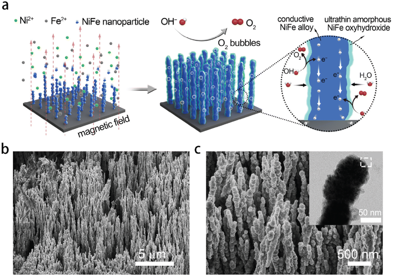 | ||
| Fig. 5 Morphological and structural characterisation of NixF1−x alloy-ultrathin amorphous oxyhydroxide nanowire arrays (denoted as NixF1−x-AHNAs). (a) Schematic of the synthesis of the NixF1−x-AHNAs nanowires arrays and its catalytic function for the OER. (b and c) SEM images of NixF1−x-AHNAs at different magnifications. Inset of (c) is a low magnification TEM of a single nanowire. Reproduced from ref. 179 with permission from the Royal Society of Chemistry, Copyright ©2020. | ||
Wu and colleagues181 demonstrated outstanding activity of NiFe2O4/NiFe LDH on Ni foam in 1 M KOH, which required only low overpotentials of 242 mV and 265 mV to produce 500 mA cm−2 and 1000 mA cm−2, respectively. The current densities were 97% retained during 20 h stability test at overpotentials of 202 mV, 230 mV, and 242 mV with barely any change in morphology and microstructure. The authors proposed a NiFe2O4 nanoparticles/NiFe LDH nanosheet array on Ni foam. The NiFe LDH nanosheets were firstly formed on the Ni foam substrate by a solvothermal method. Then NiFe2O4 particles were deposited on the NiFe LDH nanosheet via a hydrolysis approach. This process not only provided good electrical contact between the catalyst and Ni foam substrate but enhanced the catalytically active surface area, which indicated high intrinsic electrochemically activity.
A slightly higher overpotential was reported by Teng et al.182 for NiFeOx nanotube arrays, which achieved 100 mA cm−2 and 1000 mA cm−2 in 1 M KOH at overpotentials of 260 mV and 350 mV, respectively, with a Tafel slope of 47 mV dec−1. Little degradation in the OER performance with negligible change in morphology was observed after operating at a fixed overpotential of 260 mV for 12 h.
Xiao and colleagues183 constructed the porous composite electrode NiFe/NiCo2O4/NF via a 2-step deposition procedure. The catalyst produced a current density of 1200 mA cm−2 with an overpotential of 340 mV in 1 M KOH solution, at room temperature. This electrode comprised three levels of porous structure, including macroporous Ni foam substrate (∼500 μm thickness), an intermediate vertically aligned macroporous layer of NiCo2O4 nanoflakes (∼500 nm thickness) formed in a hydrothermal reaction, and the top layer of NiFe(oxy) hydroxide mesoporous nanosheets (∼5 nm thick) formed by an electrodeposition method. The authors claimed that the catalytic activity was predominantly contributed by the topmost NiFe layer, while the presence of NiCo2O4 nanoflakes layer increased the active surface areas significantly.
Jiang et al.184 showed that Ni3Fe0.5V0.5 ultrathin nanosheets grown on hydrophilic carbon fiber paper by a hydrothermal method exhibited a very low overpotential of 300 mV to produce 1000 mA cm−2 in 1 M KOH electrolyte at room temperature, with a Tafel slope of 39 mV dec−1. As mentioned above however, the presence of carbon as a substrate in OER catalysts leads to false and misleading anodic currents that do not reflect the OER activity. A question therefore exists over this result.142
Developing NiFe LDH-based catalyst with more active sites on different conductive skeletons has been considered as an alternative approach to improve OER activity and stability.
Liu et al.185 fabricated a thin film NiFe LDH nanosheet array on a Fe foam substrate via a corrosion reaction of the Fe foam with a corrosive solution of nickel salts (e.g. NiSO4·6H2O) at room temperature for 12 h. In this solution, Fe-layered double hydroxides were spontaneously formed rather than the formation of common Fe rust (Fig. 6(a)) due to the presence of divalent Ni2+ in the corrosive solution. The layered double hydroxides were well-oriented with abundant grain boundaries to create a nanosheet array architecture, which was believed to enhance the electrochemical reaction (Fig. 6(b)). The NiFe LDH nanosheet array, prepared by a corrosion engineering method, displayed higher OER performance than NiFe LDH prepared by the electrodeposition method. At room temperature, this electrode required only 300 mV and 340 mV to generate 500 mA cm−2 and 1000 mA cm−2 in 1 M KOH, respectively, and 257 mV and 280 mV for the same current densities in 10 M KOH. It also showed robust stability at room temperature with negligible decay at 1000 mA cm−2 for 5000 h in 1 M KOH (Fig. 6(c)), followed by 1050 h in 10 M KOH (Fig. 6(d)). Iron substrates may, however, be expected to be subject to rapid corrosion by dissolved oxygen (forming iron oxides),186 so that the practical utility of this result is also open to question.
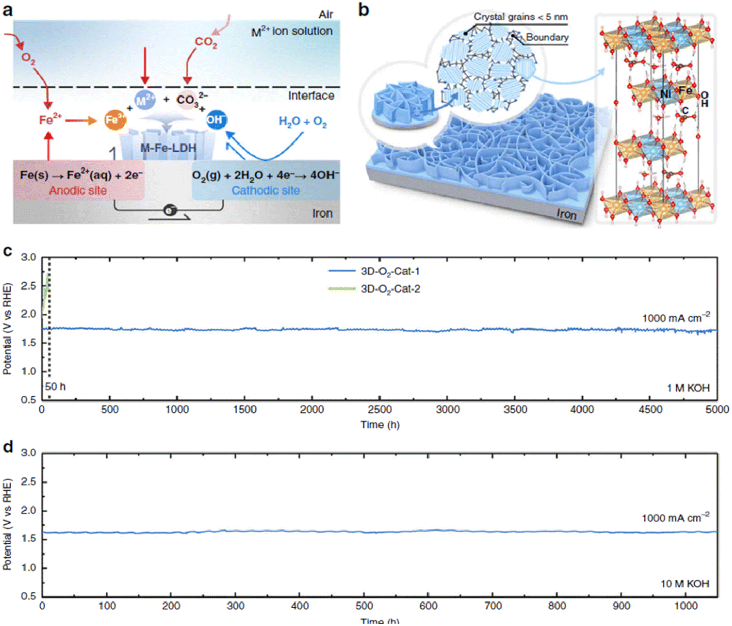 | ||
| Fig. 6 (a) Schematic diagram depicts specific reaction of the formation NiFe LDH catalyst on iron substrate by a corrosion engineering method. (b) The formation of grain boundary-enriched layered double hydroxide (LDH) nanosheet arrays on the Fe substrate surface. Right side of (b) shows the representative crystal structure of LDH. (c and d) Chronopotentiometric curves at room temperature of NiFe LDH (3D-O2-Cat-1) for 5000 h (c) in 1 M KOH, and then for 1050 h (d) in 10 M KOH at current density of 1000 mA cm−2. Reproduced from ref. 185 with permission. Copyright ©2018. The Authors, some rights reserved; exclusive licensee Springer Nature. Distributed under a Creative Commons Attribution License 4.0 (CC BY) https://protect-au.mimecast.com/s/4B4DCRON66hym235F9sxMx?domain=creativecommons.org/. | ||
Yu et al.187 reported NiFe-LDH nanostructures grown vertically on Cu nanowire arrays, which were able to generate 1000 mA cm−2 at 315 mV overpotential in 1 M KOH at room temperature, with a very small Tafel slope of 27.8 mV dec−1. The shell of the NiFe LDH nanosheets grew vertically around the core of the Cu nanowires, forming a highly porous structure that provided many channels for electrolyte diffusion and gas diffusion. There was no increase of overpotential during 48 h stability test at current densities of 10 mA cm−2 and 100 mA cm−2 in 1 M KOH at room temperature. However, a small change in the morphology and phase of the original 3D porous structure was observed after the stability test. It is also probably due to the fact that Cu likely dissolved in 1 M KOH electrolyte during the test.188
Shen et al.189 developed Ni(Fe)OxHy-coated nano-cone array stainless steel meshes, which achieved high current densities of 500 mA cm−2 and 1000 mA cm−2 at overpotentials of 280 mV and 303 mV, respectively, in 1 M KOH electrolyte at 25 °C, with a small Tafel slope of 34.9 mV dec−1. However, the nano-cone on the electrode surface dropped off after 82 h of electrolysis at 500 mA cm−2, resulting in an increase in the overpotential of 15 mV.
In order to improve the activity of NiFe (oxy)hydroxide, the incorporation of a third metal has also been studied. Wang et al.190 fabricated NiFe (sulfur) oxyhydroxide on Ni foam substrate by a facile one-step, wet synthesis method. This electrode produced a current density of 1000 mA cm−2 at 260 mV overpotential in 1 M KOH at room temperature.
Liu et al.191 also reported carbon-free nano-NiCoFe layered double hydroxides (LDHs) with MoO42− anions to alleviate the issues of carbon corrosion and catalytic stability of most electrocatalysts of OER.
Zou et al.192 reported a NiFe hydroxide integrated with a Ni3S2 nanostructure supported on Ni foam via a novel 2-step method, which possessed high catalytic activity in both 1 M KOH and 30 wt% KOH solution. Firstly, Ni3S2/NF was synthesized via a hydrothermal method in a solution containing a source of sulfur.193 Then, amorphous Ni–Fe bimetallic hydroxide was grown on the Ni3S2/NF skeleton by immersion of as-prepared Ni3S2/NF into a pre-heated (100 °C) solution containing Fe3+ ion for 5 s. The resulting electrode generated 500 mA cm−2, 1000 mA cm−2, and 1500 mA cm−2 at overpotentials of 370 mV, 469 mV, and 565 mV, respectively, in 30 wt% KOH electrolyte at room temperature. The catalytic stability was also assessed by recording chronopotentiometric curves at 100 mA cm−2 and 500 mA cm−2 in 1 M KOH and 1000 mA cm−2 in 30 wt% KOH solution, with negligible loss after 50 h of operation under ambient condition. The 3D Ni3S2 nanosheet arrays were said to provide not only faster electron transport but also higher electrochemically active surface areas to the electrode.
During the drafting of this publication, Jiang et al.194 reported Ni3Fe LDH synthesized by a co-precipitation method from Ni(NO3)2 and Fe(NO3)3 in alkaline solution, which exhibited a low overpotential of 249 mV at 10 mA cm−2 in 1 M KOH electrolyte, room temperature, with an ultra-small Tafel slope of 24 mV dec−1. To evaluate stability, Ni3Fe LDH with a 0.2 mg cm−2 loading on Ni foam was tested at a fixed voltage of 1.6 V for 400 h in 1 M KOH. This catalyst displayed good stability with a degradation in current of 0.0261 mA cm−2 h−1, equating to current density loss of 10.44 mA cm−2 after 400 h operation. However, the Ni3Fe LDH catalyst required a relatively long preparative process including drying in a vacuum oven overnight at 25 °C, which may limit its practicality in large scale applications.
Several approaches to synthesize metal-hydroxide catalyst for OER in the literature are described in Table 4.
| Catalyst | Method | Substrate | Operating conditions | Performance | Tafel slope (mV dec−1) | Ref. |
|---|---|---|---|---|---|---|
| Ni(OOH)2 | Hydrothermal at 120 °C | Ni foam | 0.1 M KOH, 23 °C | 30 mA cm−2 @ 450 mV | 65 | 65 |
| 30 mA cm−2 @ 280 mV | 50 | |||||
| NiFe-LDH | Compared with NF (520 mV for 30 mA cm−2) | |||||
| NiFe(OH)2 | Electrodeposition | Nickel microdisc | 1 M NaOH, 80 °C | 500 mA cm−2 @ 265 mV | 33 | 173 |
| NiFe-hydroxide | Electrodeposition | Ni foam | 10 M KOH, 23 °C | 500 mA cm−2 @ 240 mV | 32 | 64 |
| NiFe-LDH (Ni:Fe = 3:1 wt%) |
Electrodeposition | Stainless steel | 30% KOH, 23 °C | 300 mA cm−2 @ 396 mV | 40 | 195 |
| NiFe-LDH | Electrodeposition | Ni foam | 1 M KOH, 23 °C | 10 mA cm−2 @ 224 mV | 52 | 196 |
| NiFe film | Electrodeposition | Au | 0.1 M KOH, 23 °C | 10 mA cm−2 @ 280 mV | 40 | 174 |
| NiFe-LDH/X where X refers to different anion intercalation into LDH structure | Hydrothermal at 25 °C in different Ni salts solution | Fe foam | 1 M KOH, 23 °C | 197 | ||
| NiFe-LDH/Cl− | NiCl2 | 10 and 100 mA cm−2 @ 230 and 260 mV (for NiCl2) | 53.1 | |||
| NiFe-LDH/NO3− | Ni(NO3)2 | 10 and 100 mA cm−2 @ 210 and 240 mV (for Ni(NO3)2) | 40.4 | |||
| NiFe-LDH/SO42− | NiSO4 | 10 and 100 mA cm−2 @ 235 and 270 mV (for NiSO4) | 56.5 | |||
| NiCo-LDH | Electrodeposition | Stainless steel | 1 M KOH, 23 °C | 10 mA cm−2 @ 270 mV | 61 | 198 |
| NiMn-LDH nanosheet | Coprecipitation + hydrothermal | GCE | 0.1 M NaOH, 23 °C | 10 mA cm−2 @ 330 mV | 47 | 199 |
| CoFe-LDH | Coprecipitation | Ni foam | 0.1 M KOH, 23 °C | 10 mA cm−2 @ 320 mV | 45 | 200 |
| Ultrathin CoFe-LDH | Coprecipitation | Ni foam | 1 M KOH, 23 °C | 100 mA cm−2 @ 310 mV | 47 | 201 |
| Ultrathin CoMn-LDH | Coprecipitation | CFP (pretreated with O2 plasma) | 1 M KOH, 23 °C | 10 mA cm−2 @ 324 mV | 43 | 202 |
5.2 Non-oxide catalysts for the OER
Non-oxide catalysts for the OER have received less attention than metal-oxides (or hydroxides/oxyhydroxides). Transition metal phosphides, sulfides and selenides have been reported as electrocatalysts for the OER. Of most interest are Ni- and Co-based compounds because they possess high conductivity.16 Among these, phosphides and sulfides have exhibited good catalytic activity. For instance, Zheng et al.203 reported Ni2P grown on Ni foam via hydrothermal treatment method with reaction time of 6 h, which needed an overpotential of 142 mV to deliver 10 mA cm−2 in 1 M KOH at room temperature. In addition, their long-term stability may be improved by uniformly doping Fe into the Ni2P phase; the resulting electrode exhibited an overpotential of 150 mV at 10 mA cm−2.204 In addition, according to Xu et al.205 NiFe-selenides can drive higher OER activity because they transform to an oxide and oxyhydroxide phase on their surface.One of the highest performing catalysts, Fe(PO3)2/Ni2P supported on Ni foam, has been reported by Zhou and colleagues.206 This electrode yielded current densities of 10 mA cm−2 at an overpotential of 177 mV, and 500 mA cm−2 at 265 mV. At room temperature, it also produced 1705 mA cm−2 at only 300 mV in 1 M KOH solution and demonstrated good stability at 100 mA cm−2 and 500 mA cm−2 for 20 h. The predominant contribution to the large current density was by the Fe(PO3)2. The catalytic activity improved after the first 1000 cycles of cyclic voltammetry testing and maintained mostly the same performance after 10000 cycles due to the formation of amorphous FeOOH on the Ni foam during OER operation.
Ren et al.207 reported on the NiMoN@NiFeN transition metal nitride (TMN) as an electrocatalyst for the OER, where NiFeN nanoparticles were decorated on NiMoN nanorods supported on porous Ni foam. Very low overpotentials of 337 mV and 368 mV were required to deliver large current densities of 500 and 1000 mA cm−2, respectively, in 1 M KOH at 25 °C. The authors attributed the high performance of this electrocatalyst to the in situ evolved amorphous layers of NiFe oxide and NiFe oxyhydroxide on the electrode surface. In addition, the integrated 3D core–shell TMN nanostructure allowed ions or molecules to access the interior volumes, increasing active sites and promoting OER performance.
In a recent report, Chen and Hu99 developed a highly activity OER catalyst from HER catalyst NiMo–NH3/H2 by doping Fe ions into it to create Fe–NiMo–NH3/H2. To prepare this catalyst, NiMoO4 was first annealed on a Ni foam in a mixture of H2/NH3 (5% H2) at 550 °C for 2 h to form NiMo–NH3/H2. The as-synthesized NiMo–NH3/H2 was then dipped into a fresh FeCl3 solution (1 mM) for 15 min for the growth of FeOOH nanoclusters onto the NiMo-based electrode. Finally, the Fe–NiMo–NH3/H2 electrode was obtained after drying in an oven at 70 °C, followed by in air for 1 h. This electrode catalyzed the OER at 500 mA cm−2 at an overpotential of only 244 mV in 1 M KOH solution at room temperature. It also exhibited stable performance in 18 h for electrolysis at 1.46 V with negligible change in the current density. After catalytic OER operation, Mo and N was observed to be lost, suggesting that an amorphous NiFe oxyhydroxide layer formed on the electrode surface; this may explain the high OER performance. Although the original catalyst was not an oxide, during OER electrolysis, a structural transformation to an oxide or oxyhydroxide phase occurred on the electrode surface, thereby producing high OER activity. It is, accordingly, essential to accurately understand the catalytic mechanism in order to design high performing catalytic materials.
6. Bifunctional catalysts for the HER and OER
Noble Pt/C, RuO2, and IrO2 or even the transition metal-based catalysts that are functional for only single half-cell reactions make it cost efficient to develop efficient bifunctional catalysts capable of catalyzing both the HER and OER.Using zeolitic imidazole framework (ZIF) structures, Song et al.,209 reported a hybrid nanostructure with CoP nanoparticles embedded in an hollow N-doped carbon nanocage which they termed as h-CoP@NC. With these novel structures, the authors could able to address some of the problems usually encounter in catalysis such as mass transport and agglomeration of nanoparticles. The optimal electrocatalyst exhibited superior bifunctional activities for both the HER and OER with overpotentials of 196 mV and 339 mV respectively to drive a 10 mA cm−2 current; an cell voltage of 1.764 V was required for overall water splitting.209
Ji et al.208 on the other hand, incorporated heteroatoms such as Ni and Co in the N-doped carbon matrix to create (Ni,Co)2P nanoframes (NFs) that were studied as HER and OER catalysts. The work showed that when the (Ni,Co)2P NF catalyst was employed as both the cathode and anode for overall water splitting, a remarkably low cell voltage of 1.54 V was required to achieve a current density of 10 mA cm−2, with overpotentials of 92 mV for the HER and 283 mV for the OER in 1 M KOH at room temperature, respectively.210 Interestingly the same synthetic strategy (see Fig. 7) for preparing nanoframes could be extended to the preparation of other sulphides and selenides, such as (Ni,Co)S2 NFs and (Ni,Co)Se2 NFs.
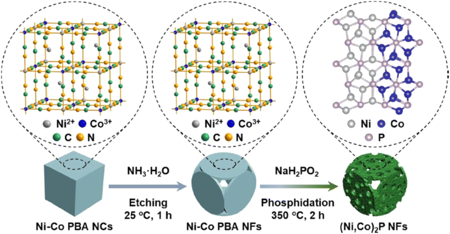 | ||
| Fig. 7 Schematic synthesis route for (Ni,Co)2P NFs. Reproduced from ref. 208 with permission from American Chemical Society, Copyright ©2021. | ||
Yu et al.119 constructed metallic iron and dinickel phosphides (FeP/N2P) on commercial Ni foam for both HER and OER catalysts. The cell required only 1.42 V to generate 10 mA cm−2 with a low Tafel slope of 69.5 mV dec−1 in 1 M KOH electrolyte, room temperature. It also delivered current densities of 500 and 1000 mA cm−2 at low voltage of 1.72 and 1.78 V, respectively, and exhibited excellent stability at 500 mA cm−2 during 40 h of operation in 1 M KOH at room temperature with negligible degradation. The work showed that FeP particles grown on top of a highly conductive, high surface area of Ni2P/Ni foam support enhanced OER performance due to improvement of catalytic activity with Fe incorporation.178 Density functional theory (DFT) measurement showed a significant decrease in hydrogen adsorption energy of FeP/Ni2P catalysts compared to pure Ni2P, indicating that this catalyst was efficient for HER. This conclusion was also supported by TOF calculations, with TOF values for FeP/Ni2P calculated to be 0.163 s−1 at 100 mV overpotential compared to 0.006 s−1 for pure Ni2P catalyst at the same overpotential.
7. High-performance alkaline water electrolysis
The next step toward industrial applications would be to investigate full-cell, 2-electrode water electrolysis, with simultaneous generation of hydrogen at the cathode and oxygen at the anode. The development of high performing electrocatalysts for efficient and durable overall water splitting in commercial alkaline electrolysers are of critical importance in further decreasing the cost of green hydrogen.The hydrogen production rate is directly proportional to the current density employed. However, increasing the current density decreases the energy efficiency. Both parameters have a direct impact on the cost of hydrogen production. In practice, the energy efficiency and the hydrogen production rate should be considered when designing an electrolyser system.
Chen and Hu99 reported a high-efficiency anion exchange membrane (AEM) water electrolysis cell, which employed NiMo–NH3/H2 as a cathode and Fe–NiMo–NH3/H2 as an anode. The cell produced 1000 mA cm−2 at 1.57 V at 80 °C in 1 M KOH electrolyte, which corresponds to 93.6% energy efficiency relative to the higher heating value (HHV) of hydrogen. In addition, this cell displayed excellent stability when operated at 50 mA cm−2 at 80 °C but at a constant current density of 500 mA cm−2 degradation was observed after 25 h operation.
Masel's group developed a ‘Sustanion’ anion exchange membrane-based alkaline electrolyser, which generated 1000 mA cm−2 at 1.9 V at 60 °C with a NiFe2O4 anode and FeNiCo cathode catalyst on stainless steel fibers. The cell maintained excellent stability at 1000 mA cm−2 for 2000 h giving a degradation rate of only 5 μV h−1.211 With a precious metal Pt/C catalyst at the cathode and IrO2 at the anode on the Sigracet carbon fiber paper, the cell delivered 1000 mA cm−2 at 1.63 V, however its stability was not reported.211 The carbon used at the anode likely produced an artefact result reflecting carbon corrosion rather than OER catalysis.
Alchemr's water electrolyser cells (5 cm2) employed a Sustanion membrane, NiFe2O4 catalyst on a stainless-steel gas diffusion layer at the anode, and a modified RANEY® Ni on Ni fiber paper at the cathode. The cell produced a stable performance of 1000 mA cm−2 at 1.85 V at 60 °C in 1 M KOH, with voltage decay of less than 1 μV h−1 over 10000 h.210 Regarding the industrial requirement of limiting the performance loss of the catalysts to less than 10% of the initial performance at end-of-life (from 1.85 V to 2.035 V): the authors assumed that a commercial system must maintain >90% of initial performance (at the end the system will be at 2.035 V), then 1 μV h−1 degradation gives (2.035–1.85)/10−6 = 185000 h = ∼21 years lifetime. This met the industrial performance requirement.
In another report, a cell consisting of a RANEY®-type NiMo cathode, RANEY®-Ni anode and a m-PBI inter-electrode separator membrane (40 μm thick) developed by Kraglund et al.212 generated 1700 mA cm−2 at 1.8 V in 24% KOH solution at 80 °C. However, the cell failed after 120 h of stability test due to mechanical failure of the membrane. When using an 80 μm thick membrane, the failure was observed at roughly double the lifetime of 230 h.
Zhou and colleagues178 constructed a highly efficient electrolyser with a (Ni,Fe)OOH catalyst at the anode and a robust MoNi4 catalyst at the cathode. Both electrodes used Ni foam as a substrate. The cell produced current densities of 500 mA cm−2 and 1000 mA cm−2 at only 1.586 V and 1.657 V, respectively, in 1 M KOH at room temperature. It sustained that performance with only a small voltage drift for 40 h when operated at constant current densities of 500 mA cm−2, 1000 mA cm−2, and 1500 mA cm−2.
In a separate study, Liang et al.179 combined a Ni0.8Fe0.2 amorphous oxyhydroxide nanowire array at the anode with a Ni nanowire array at the cathode in an alkaline electrolyser, that produced current densities of 500 mA cm−2 and 1000 mA cm−2 at low cell voltages of 1.70 V and 1.76 V, respectively, in 1 M KOH at room temperature.
By using a commercially available polyethersulfone (PES) ultrafiltration membrane with 0.2 μm pore size and 140 μm thickness as a separator between two Ni-based electrodes in a zero-gap configuration, Schalenbach et al.213 reported a high current density of 2000 mA cm−2 at a cell voltage of 1.85 V at 80 °C in 30 wt% aqueous KOH solution. However, the voltage increased by 20 mV during an 8 h stability test at 500 mA cm−2 at 80 °C. The performance recovered after the cell was shut down for the night. This could be explained by the formation of bubbles, which covered the electrodes, resulting in masking of the active sites of the electrodes. The performance only fully recovered when the gas bubbles were released from electrode surface after the cell was shut down.
Interestingly, using a similar PES membrane but different pore size (8 μm), a unique concept of water electrolysis, namely, the capillary-fed electrolyser developed by Swiegers and colleagues,8 produced the highest performance yet reported for an electrolysis cell at 80–85 °C. In this configuration, water was supplied to both electrodes via capillary-induced transport up and along the PES membrane. Commercial catalysts were employed, with Pt/C on Sigracet carbon fiber paper at the cathode and NiFeOOH with PTFE on Ni mesh at the anode. This cell exhibited outstanding performance at 500 mA cm−2 and 1000 mA cm−2 requiring cell voltages of only 1.506 and 1.575 V, respectively, at 85 °C in 27 wt% aqueous KOH; this equated to a cell energy efficiency of 98% and 93% (HHV) respectively. In addition, when the cell voltage was fixed at the thermoneutral voltage for water electrolysis, 1.47 V at 85 °C, which equates to 100% energy efficiency (HHV), the cell produced a constant current density of 300 mA cm−2. No water electrolysis, either alkaline or PEM, has ever produced 300 mA cm−2 at 100% energy efficiency, HHV. The capillary-fed cell also demonstrated sustained stable performance from 1 working day to 30 days continuously at 80 °C and room temperature, respectively.
Very early on, Schiller et al.143 tested a 10 kW electrolyser system with activated Mo-containing RANEY® nickel cathodes and RANEY® nickel/Co3O4 matrix composite anodes in a bipolar electrolyser with zero-gap configuration. The cell achieved 300 mA cm−2 and 500 mA cm−2 at 80 °C in 30 wt% KOH solution, at 1.60 and 1.67 V, respectively. The electrolyser stack was also tested in constant and intermittent current mode at 300 mA cm−2, 80 °C over 15000 h duration with stable performance.
Asahi Kasei demonstrated a medium size zero-gap configuration (0.3 m2 per cell), which, arguably, constitutes the state-of-the-art in commercial alkaline electrolysis. The cell operates at up to 1000 mA cm−2 and required less than 1.8 V to produce 600 mA cm−2.214
Table 5 summaries the state-of-the-art HER, OER and overall water splitting performance.
| Cathode catalyst | Anode catalyst | Electrolyte | Temperature | Current density | Durability | Ref. | |
|---|---|---|---|---|---|---|---|
| a The HER and OER catalysts were studied in 3-electrode configurations. The catalysts listed in the ‘Overall water splitting’ section were studied in 2-electrode cells. b AHNA = Amorphous oxyhydroxide nanowire arrays; CF = Carbon fibre; CNT = Carbon nanotube; HC = Hydroxide carbonate; LDH = Layered double hydroxide; NF = Nickel foam. c The value is calculated from the curves shown in literature. | |||||||
| HER (cathode) | 20 mg cm−2 NiMo | 30% KOH | 70 °C | 1000 mA cm−2 @ 80 mV | 78.7 mg cm−2 NiMo, 70 °C, 600 h @ 1000 mA cm−2, 16.6c μV h−1 | 96 | |
| 3.4–3.6 mg cm−2 NiMoFe | 8.32 M NaOH | 80 °C | 600 mA cm−2 @ 230 mV | 1500 h, 80 °C @ 300 mA cm−2, 9c μV h−1 | 93 | ||
| NiMo (75:25 wt%) |
6 M KOH | 80 °C | 300 mA cm−2 @ 185 mV | 1500 h, 80 °C @ 300 mA cm−2, negligible degradation | 94 | ||
| 40 mg cm−2 NiMo | 1 M KOH | 40 °C | 400 mA cm−2 @ 110 mV | 8 h, water, 70 °C @ 400 mA cm−2, 6250c μV h−1 | 99 | ||
| 43.4 mg cm−2 MoNi4/MoO2@Ni | 1 M KOH | 23 °C | 500 mA cm−2 @ 65 mV | 10 h, 23 °C @ 200 mA cm−2, 500c μV h−1 | 66 | ||
| 2 mg cm−2 NiMo–NH3/H2 | 1 M KOH | 23 °C | 500 mA cm−2 @ 107 mV | 20 h, 23 °C @ 0.1 V (∼410 mA cm−2), negligible degradation | 100 | ||
| NiMoN | 1 M KOH | 23 °C | 500 mA cm−2 @ 127 mV | 24 h, 23 °C @ 127 mV (∼500 mA cm−2), ∼ −0.7c mA cm−2 h−1 | 207 | ||
| 35 mg cm−2 RANEY® Ni | 28% KOH | 80 °C | 500 mA cm−2 @ 100 mV | NA | 215 | ||
| 35 mg cm−2 Ni–Cr RANEY® | 28% KOH | 80 °C | 500 mA cm−2 @ 80 mV | NA | |||
| 8 mg cm−2 NiO/Ni-CNT | 1 M KOH | 23 °C | 100 mA cm−2 @ 100 mV | 2 h, 23 °C @ 20 mA cm−2, no degradation | 216 | ||
| 8 mg cm−2 FeP/Ni2P | 1 M KOH | 23 °C | 350c and 1000c mA cm−2 @ 200 and 270 mV | 24 h, 23 °C @ 100 mA cm−2, no degradation | 119 | ||
| 1.45 mg cm−2 Pt/C/CF | 1 M KOH | 23 °C | 20 mA cm−2 @ 45 mV | NA | 81 | ||
| OER (anode) | 2.78 mg cm−2 NiFe LDH on Fe foam | 1 M KOH | 23 °C | 500 and 1000 mA cm−2 @ 300 and 340 mV | 5000 h, 23 °C @ 1000 mA cm−2, negligible degradation | 185 | |
| 10 M KOH | 500 and 1000 mA cm−2 @ 257 and 280 mV | 1050 h, 23 °C @ 1000 mA cm−2, negligible degradation | |||||
| 4.0 mg cm−2 NiFe(OOH)/NF | 1 M KOH | 23 °C | 500 and 1000 mA cm−2 @ 259 and 289 mV | 44 h, 23 °C @ 500 mA cm−2, 318c μV h−1 | 178 | ||
| 44 h, 23 °C @ 1000 mA cm−2, 1341c μV h−1 | |||||||
| 2.5 mg cm −2 Ni0.8Fe0.2-AHNA | 1 M KOH | 23 °C | 500 and 1000 mA cm−2 @ 248 and 258 mV | 120 h, 23 °C @ 5 constant current densities (10, 100, 500, 1000 and 10 mA cm−2), negligible degradation | 179 | ||
| 2.8 mg cm−2 NiFe2O4/NiFe LDH/NF | 1 M KOH | 23 °C | 500 and 1000 mA cm−2 @ 242 and 265 mV | 20 h, 23 °C @ 242 mV (∼500 mA cm−2), 97% retaining (∼−0.75c mA cm−2 h−1) | 181 | ||
| NiFeOx on | 1 M KOH | 23 °C | 1000 mA cm−2 @ 300 mV | 10 h, 10 M KOH, 23 °C @ 480 mV (∼1400 mA cm−2), negligible degradation | 217 | ||
| Fe foam | |||||||
| NiFe/NiCo2O4/NF | 1 M KOH | 23 °C | 1200 mA cm−2 @ 340 mV | 10 h, 23 °C @ 50 mA cm−2, negligible degradation | 183 | ||
| Ni(Fe)OxHy on stainless steel | 1 M KOH | 23 °C | 500 and 1000 mA cm−2 @ 280 and 303 mV | 82 h, 23 °C @ 500 mA cm−2, 182.9c μV h−1 | 189 | ||
| NiFeOH@Ni3S2/NF | 30% KOH | 23 °C | 500 and 1000 mA cm−2 @ 370 and 469 mV | 50 h, 1 M KOH, 23 °C @ 500 mA cm−2, negligible degradation | 192 | ||
| 50 h, 30% KOH, 23 °C @ 1000 mA cm−2, negligible degradation | |||||||
| 8 mg cm−2 Fe(PO3)2/Ni2P/NF | 1 M KOH | 23 °C | 500 and 1705 mA cm−2 @ 265 and 300 mV | 20 h, 23 °C @ 500 mA cm−2, negligible degradation | 206 | ||
| 8 mg cm−2 FeP/Ni2P | 1 M KOH | 23 °C | 1000 mA cm−2 @ 293 mV | 24 h, 23 °C @ 100 mA cm−2, no degradation | 119 | ||
| NiMoN@NiFeN/NF | 1 M KOH | 23 °C | 500 and 1000c mA cm−2 @ 337 and 370 mV | 24 h, 23 °C @ 337 mV (∼500 mA cm−2), −0.775 mA cm−2 h−1 | 207 | ||
| NiFe-HC | 1 M KOH | 23 °C | 400 mA cm−2 @ 370 mV | NA | 176 | ||
| Overall water splitting | NiMo–NH3/H2 | Fe–NiMo–NH3/H2 | 1 M KOH | 80 °C | 1000 mA cm−2 @ 1.57 V | 25 h, 80 °C @ 50 mA cm−2, negligible degradation | 100 |
| 25 h, 80 °C @ 500 mA cm−2, degradation observed | |||||||
| FeNiCo on stainless-steel fiber | NiFe2O4 on stainless-steel fiber | 1 M KOH | 60 °C | 1000 mA cm−2 @ 1.9 V | 2000 h, 60 °C @ 1000 mA cm−2, 5 μV h−1 | 212 | |
| RANEY® Ni on Ni fiber paper | NiFe2O4 on stainless-steel | 1 M KOH | 60 °C | 1, 000 mA cm−2 @ 1.85V | 10000 h, 60 °C @ 1000 mA cm−2, 1 μV h−1 |
200 | |
| MoNi4 | (Ni,Fe)OOH | 1 M KOH | 23 °C | 500 and 1000 mA cm−2 @ 1.586 and 1.657 V | 40 h, 23 °C @ current densities of 500, 1000 and 1500 mA cm−2, small degradation | 178 | |
| Ni nanowire array | Ni0.8Fe0.2-AHNA | 1 M KOH | 23 °C | 500 and 1000 mA cm−2 @ 1.70 and 1.76 V | 24 h, 23 °C @ 500 mA cm−2, negligible degradation | 179 | |
| Pt/C | NiFeOOH/PTFE | 27% KOH | 80 °C | 300 mA cm−2 @ 1.47 V | 30 days, 23 °C @ 400 mA cm−2, negligible degradation | 8 | |
| 1000 mA cm−2 @ 1.59 V | |||||||
| RANEY®-type-NiMo | RANEY® Ni | 24% KOH | 80 °C | 1700 mA cm−2 @ 1.8 V | The cell failed after 120 h of operation at 80 °C | 212 | |
| Ni mesh | NiFe-HC | 6 M KOH + 2 M K2CO3 + 0.5 M NaCl | 80 °C | NA | 1500 h, 80 °C @ 400 mA cm−2, negligible degradation | 179 | |
| Mo-containing RANEY® Ni | RANEY® Ni/Co3O4 | 30% KOH | 80 °C | 300 mA cm−2 @ 1.6 V | 15000 h, 80 °C @ 300 mA cm−2, negligible degradation |
143 | |
| FeP/Ni2P | FeP/Ni2P | 1 M KOH | 23 °C | 500 and 1000 mA cm−2 @ 1.72 and 1.78 V | 40 h, 23 °C @ 500 mA cm−2, negligible degradation | 119 | |
8. Conclusions and perspectives
‘Green’ hydrogen has been identified as an alternative energy carrier to fossil fuels, that could help achieve global net-zero carbon emission in the coming decades. However, green hydrogen is, today, still expensive due to the low energy efficiency of its production process. Reducing the cost of green hydrogen is critical for effective translation of hydrogen solutions in the transport and energy sector. Improving the efficiency of alkaline water splitting via high-performing catalysts offers a viable means of reducing the cost of green hydrogen.It is vital however, to develop electrocatalysts that are suitable for industrial electrolysers. That is, they need to be high performing under industrially relevant conditions, which include high current density (for example, 200–700 mA cm−2), long-term durability without significant degradation to end-of-life, and at desired pressures and temperatures. Despite the efforts directed to electrocatalyst development, the absolute necessity of durability in commercial applications (10 years or more) has largely been overlooked in previous studies. Studies of catalysts at low current densities over short periods of testing, during which degradation may often be observed, as has been widely practiced in the field, are, frankly, not useful in this regard.
This review has summarised recent progress in the development of such electrocatalysts for the HER and OER, with the aim of identifying systems for high-efficiency water electrolysis in alkaline environment. The work has focused on materials, synthesis methods, electrochemical performance and the related mechanism of activity enhancement.
With regard to hydrogen evolution, Pt-group catalysts stand as the state-of-the-art electrocatalyst due to their low overpotential for HER. However, the high cost and scarcity of precious metals limit their application in industrial water splitting. A move toward developing earth-abundant materials for HER is still required. These materials should exhibit not only high catalytic activity but be easily scaled-up for practical application in alkaline medium.
NiMo-based alloys or its alloy doped with Fe constitute the most promising alternatives to noble metal-based catalysts for the HER. These catalysts exhibit high catalytic activity and stable performance at the operating conditions of commercial electrolysers.
There has been great interest in developing a high performing OER electrocatalyst due to the sluggish kinetics of the anode, which results in a significant loss of energy. Many studies have focused on Ni, Fe, Co, and Mn oxide materials and their combinations since these metal oxide electrocatalysts generally exhibit excellent catalytic activities for oxygen evolution in alkaline media. Among them, NiFe-based catalysts have been shown to exhibit great potential in large-scale commercial water electrolysis due to their easily scalable fabrication and stable performance at large current densities for long times. It appears to the authors that NiFe oxides, double hydroxides, and oxyhydroxides offer the most promising OER catalysts for efficient, high-performing oxygen evolution.
Non-oxide catalysts in the form of transition metal phosphides and selenides also demonstrate enhanced catalytic activity for both the HER and OER, showing promising potential for bifunctional electrocatalysts that facilitate overall water splitting.
Although intensive efforts have been made to develop high-performing catalysts that increase the efficiency of alkaline electrolysis, some challenges still need to be overcome, including:
(i) 3D electrode fabrication: generally, catalysts can be easily prepared by coating on a conductive substrate with or without a polymer binder, followed by an annealing process at high temperature to improve adhesion between catalyst and substrate. Growing electrocatalyst nanoarrays as 3D structures on a catalyst support is considered as an alternative, more preferred solution, which not only increases the number of active sites but accelerates mass and charge transfer processes; it also enhances electrical conductivity between the catalyst and substrate. However, to be practically useful in commercial electrolysers, such fabrication processes need to be amenable to high-volume electrode manufacturing techniques. While significant and promising progress has been made, further work is needed on fabrication methods that impart the electrode structure with optimum catalytic performance whilst also being capable of mass manufacturing for commercial electrolysers.
(ii) Developing standards for catalyst evaluation relevant to commercial-scale electrolysers: significant differences in catalytic performance may be observed by different groups when examining catalysts having the same composition and structure. Such differences may be due to different fabrication methods, catalyst loadings, reactant electrolytes, testing conditions, and so on. Therefore, benchmarking and assessment of the performance of catalysts under industrial-relevant conditions is very much needed. Newly developed catalytic electrodes should sustain current densities of 200–700 mA cm−2 or higher (1000 mA cm−2) without electrochemical degradation (at least for several days) in 25–30% KOH electrolyte at elevated temperatures (60–90 °C).14 Additionally, stability and durability tests need to be taken into consideration in a more efficient and time-saving manner. The trade-off between catalytic performance and electrode stability needs to be explicitly considered.
(iii) The economic cost of catalysts/electrodes in industrial-scale applications: translation of fabrication methods from the laboratory to industry needs to consider the cost (and practicality) of large-scale electrode production for commercial electrolysers. Catalytic electrodes must be manufacturable by low-cost procedures that require little time to complete.
In fact, developing highly performing catalysts should be combined with improvements in the inter-electrode separator membrane as well as changes in cell design to obtain further reductions in cell voltage for overall water splitting.
Abbreviations
| AEM | Anion Exchange Membrane |
| CFP | Carbon Fiber Paper |
| CNT | Carbon Nanotube |
| COP26 | Conference of the Parties 26 |
| ECSA | Electrochemically Active Surface Area |
| GCE | Glassy Carbon Electrode |
| HER | Hydrogen Evolution Reaction |
| HHV | Higher Heating Value |
| LSV | Linear Sweep Voltammetry |
| LDH | Layered Double Hydroxide |
| NF | Nickel Foam |
| OER | Oxygen Evolution Reaction |
| PES | Polyether Sulfone |
| RHE | Reversible Hydrogen Electrode |
| SHE | Standard Hydrogen Electrode |
| STM | Scanning Tunneling Microscopy |
| TOF | Turnover Frequency |
Conflicts of interest
The authors have no interests to declare in respect of this manuscript.Acknowledgements
The authors gratefully acknowledge support from the Australian Renewable Energy Agency (ARENA), Grant number 2018/DM015 (entitled: Ammonia Production from Renewables) (G. F. S. & G. G. W.). This activity received funding from ARENA as part of ARENA's Research and Development Program – Renewable Hydrogen for Export. Support from the Australian Research Council Centre of Excellence Scheme (grant number CE140100012) (G. G. W. and others) and the Australian National Fabrication Facility (ANFF) Materials Node is also acknowledged. The authors acknowledge the assistance of the University of Wollongong Electron Microscopy Centre. This research used equipment funded by the Australian Research Council—Linkage, Infrastructure, Equipment, and Facilities grant LE160100063.References
- COP26: The negotiations explained, Glasgow, U.K., 2021 Search PubMed.
- O. Schmidt, A. Gambhir, I. Staffell, A. Hawkes, J. Nelson and S. Few, Future Cost and Performance of Water Electrolysis: An Expert Elicitation Study, Int. J. Hydrogen Energy, 2017, 42(52), 30470–30492 CrossRef CAS.
- G. F. Swiegers, R. N. L. Terrett, G. Tsekouras, T. Tsuzuki, R. J. Pace and R. Stranger, The Prospects of Developing a Highly Energy-Efficient Water Electrolyser by Eliminating or Mitigating Bubble Effects, Sustainable Energy Fuels, 2021, 5(5), 1280–1310 RSC see also: G. F. Swiegers, A. L. Hoang, A. Hodges, G. Tsekouras, C.-Y. Lee, K. Wagner and G. Wallace, Current status of membraneless water electrolysis cells, Curr. Opin. Electrochem., 2022, 32, 100881 CrossRef CAS.
- J. Li, Y. Zhu, W. Chen, Z. Lu, J. Xu, A. Pei, Y. Peng, X. Zheng, Z. Zhang, S. Chu and Y. Cui, Breathing-Mimicking Electrocatalysis for Oxygen Evolution and Reduction, Joule, 2019, 3(2), 557–569 CrossRef CAS.
- P. Tiwari, G. Tsekouras, K. Wagner, G. F. Swiegers and G. G. Wallace, A new Class of Bubble-Free Water Electrolyzer that is Intrinsically Highly Efficient, Int. J. Hydrogen Energy, 2019, 44(42), 23568–23579 CrossRef CAS.
- O. Winther-Jensen, K. Chatjaroenporn, B. Winther-Jensen and D. R. MacFarlane, Towards Hydrogen Production Using a Breathable Electrode Structure to Directly Separate Gases in the Water Splitting Reaction, Int. J. Hydrogen Energy, 2012, 37(10), 8185–8189 CrossRef CAS.
- G. Tsekouras, R. Terrett, Z. Yu, Z. Cheng, G. F. Swiegers, T. Tsuzuki, R. Stranger and R. J. Pace, Insights into the Phenomenon of ‘Bubble-Free’ Electrocatalytic Oxygen Evolution from Water, Sustainable Energy Fuels, 2021, 5(3), 808–819 RSC.
- A. Hodges, A. L. Hoang, G. Tsekouras, K. Wagner, C.-Y. Lee, G. F. Swiegers and G. G. Wallace, A High-Performance Capillary-Fed Electrolysis Cell Promises More Cost-Competitive Renewable Hydrogen, Nat. Commun., 2022, 13(1), 1304 CrossRef CAS PubMed.
- M. Carmo, D. L. Fritz, J. Mergel and D. Stolten, A Comprehensive Review on PEM Water Electrolysis, Int. J. Hydrogen Energy, 2013, 38(12), 4901–4934 CrossRef CAS.
- X. Zhang, T. Liu, T. Guo, Z. Mu, X. Hu, K. He, X. Chen, V. P. Dravid, Z. Wu and D. Wang, High-Performance MoC Electrocatalyst for Hydrogen Evolution Reaction Enabled by Surface Sulfur Substitution, ACS Appl. Mater. Interfaces, 2021, 13(34), 40705–40712 CrossRef PubMed.
- M. A. Khan, H. Zhao, W. Zou, Z. Chen, W. Cao, J. Fang, J. Xu, L. Zhang and J. Zhang, Recent Progresses in Electrocatalysts for Water Electrolysis, Electrochem. Energy Rev., 2018, 1(4), 483–530 CrossRef CAS.
- X. Zou and Y. Zhang, Noble Metal-Free Hydrogen Evolution Catalysts for Water Splitting, Chem. Soc. Rev., 2015, 44(15), 5148–5180 RSC.
- M. S. Faber and S. Jin, Earth-Abundant Inorganic Electrocatalysts and Their Nanostructures for Energy Conversion Applications, Energy Environ. Sci., 2014, 7(11), 3519–3542 RSC.
- K. Zeng and D. Zhang, Recent Progress in Alkaline Water Electrolysis for Hydrogen Production and Applications, Prog. Energy Combust. Sci., 2010, 36(3), 307–326 CrossRef CAS.
- M. F. Lagadec and A. Grimaud, Water Electrolysers with Closed and Open Electrochemical Systems, Nat. Mater., 2020, 19(11), 1140–1150 CrossRef CAS.
- N. T. Suen, S. F. Hung, Q. Quan, N. Zhang, Y. J. Xu and H. M. Chen, Electrocatalysis for the Oxygen Evolution Reaction: Recent Development and Future Perspectives, Chem. Soc. Rev., 2017, 46(2), 337–365 RSC.
- T. Naito, T. Shinagawa, T. Nishimoto and K. Takanabe, Recent Advances in Understanding Oxygen Evolution Reaction Mechanisms over Iridium Oxide, Inorg. Chem. Front., 2021, 8(11), 2900–2917 RSC.
- J. Rossmeisl, Z. W. Qu, H. Zhu, G. J. Kroes and J. K. Nørskov, Electrolysis of Water on Oxide Surfaces, J. Electroanal. Chem., 2007, 607(1–2), 83–89 CrossRef CAS.
- J. J. Warren, T. A. Tronic and J. M. Mayer, Thermochemistry of Proton-Coupled Electron Transfer Reagents and Its Implications, Chem. Rev., 2010, 110(12), 6961–7001 CrossRef CAS.
- Z. Shi, X. Wang, J. Ge, C. Liu and W. Xing, Fundamental Understanding of the Acidic Oxygen Evolution Reaction: Mechanism Study and State-of-the-Art Catalysts, Nanoscale, 2020, 12(25), 13249–13275 RSC.
- S. Zuo, Z. P. Wu, H. Zhang and X. W. Lou, Operando Monitoring and Deciphering the Structural Evolution in Oxygen Evolution Electrocatalysis, Adv. Energy Mater., 2022, 12(8), 2103383 CrossRef CAS.
- A. Lasia, Mechanism and Kinetics of the Hydrogen Evolution Reaction, Int. J. Hydrogen Energy, 2019, 44(36), 19484–19518 CrossRef CAS.
- X. Chia, A. Y. Eng, A. Ambrosi, S. M. Tan and M. Pumera, Electrochemistry of Nanostructured Layered Transition-Metal Dichalcogenides, Chem. Rev., 2015, 115(21), 11941–11966 CrossRef CAS PubMed.
- J. K. Nørskov, T. Bligaard, A. Logadottir, J. R. Kitchin, J. G. Chen, S. Pandelov and U. Stimming, Trends in the Exchange Current for Hydrogen Evolution, J. Electrochem. Soc., 2005, 152(2), J23–J26 CrossRef.
- M. R. Kraglund, Alkaline Membrane Water Electrolysis with Non-Noble Catalysts, PhD thesis, Technical University of Denmark, Denmark, 2017 Search PubMed.
- Y. Matsumoto and E. Sato, Electrocatalytic Properties of Transition Metal Oxides for Oxygen Evolution Reaction, Mater. Chem. Phys., 1986, 14, 397–426 CrossRef CAS.
- E. Fabbri, A. Habereder, K. Waltar, R. Kötz and T. J. Schmidt, Developments and Perspectives of Oxide-Based Catalysts for the Oxygen Evolution Reaction, Catal. Sci. Technol., 2014, 4(11), 3800–3821 RSC.
- J. O. M. Bockris, Kinetics of Activation Controlled Consecutive Electrochemical Reactions: Anodic Evolution of Oxygen, J. Chem. Phys., 1956, 24(4), 817–827 CrossRef CAS.
- W. E. O'Grady, C. Iwakura, J. Huang and E. Yeager, Ruthenium Oxide Catalysts for the Oxygen Electrode, in Proceedings of the Symposium on Electrocatalysis, The Electrochemical Society, Princeton, 1974, pp. 285–302 Search PubMed.
- W. E. O'Grady, C. Iwakura and E. Yeager, Oxygen Electrocatalysis for Life Support Systems, American Society of Mechanical Engineers, Publication 76-ENAs-37, 1976, pp. 1–12 Search PubMed.
- J. Song, C. Wei, Z. F. Huang, C. Liu, L. Zeng, X. Wang and Z. J. Xu, A Review on Fundamentals for Designing Oxygen Evolution Electrocatalysts, Chem. Soc. Rev., 2020, 49(7), 2196–2214 RSC.
- A. J. Bard and L. R. Faulkner, Electrochemical Methods: Fundamentals and Applications, John Wiley & Sons, Inc., 2nd edn, 2001 Search PubMed.
- G. Zhao, K. Rui, S. X. Dou and W. Sun, Heterostructures for Electrochemical Hydrogen Evolution Reaction: A Review, Adv. Funct. Mater., 2018, 28(43), 1803291–1803316 CrossRef.
- M. F. Weber and M. J. Dignam, Efficiency of Splitting Water with Semiconducting Photoelectrodes, J. Electrochem. Soc., 1984, 131(6), 1258–1265 CrossRef CAS.
- J. Luo, J. H. Im, M. T. Mayer, M. Schreier, M. K. Nazeeruddin, N. G. Park, S. D. Tilley, H. J. Fan and M. Gratzel, Water Photolysis at 12.3% Efficiency via Perovskite Photovoltaics and Earth-Abundant Catalysts, Science, 2014, 345(6204), 1593–1596 CrossRef CAS PubMed.
- J. D. Benck, T. R. Hellstern, J. Kibsgaard, P. Chakthranont and T. F. Jaramillo, Catalyzing the Hydrogen Evolution Reaction (HER) with Molybdenum Sulfide Nanomaterials, ACS Catal., 2014, 4(11), 3957–3971 CrossRef CAS.
- X. Zhang and Y. Liang, Nickel Hydr(oxy)oxide Nanoparticles on Metallic MoS2 Nanosheets: A Synergistic Electrocatalyst for Hydrogen Evolution Reaction, Adv. Sci., 2018, 5(2), 1700644 CrossRef.
- C. Zhang, S. Liu, Z. Mao, X. Liang and B. Chen, Ag–Ni Core–Shell Nanowires with Superior Electrocatalytic Activity for Alkaline Hydrogen Evolution Reaction, J. Mater. Chem. A, 2017, 5(32), 16646–16652 RSC.
- X. Yu, Z. Sun, Z. Yan, B. Xiang, X. Liu and P. Du, Direct Growth of Porous Crystalline NiCo2O4 Nanowire Arrays on a Conductive Electrode for High-Performance Electrocatalytic Water Oxidation, J. Mater. Chem. A, 2014, 2(48), 20823–20831 RSC.
- E. Detsi, J. B. Cook, B. Lesel, C. Turner, Y. L. Liang, S. Robbennolt and S. H. Tolbert, Mesoporous Ni60Fe30Mn10-Alloy Based Metal/Metal Oxide Composite Thick Films as Highly Active and Robust Oxygen Evolution Catalysts Dagger, Energy Environ. Sci., 2016, 9(2), 540–549 RSC.
- H. Liang, F. Meng, M. Caban-Acevedo, L. Li, A. Forticaux, L. Xiu, Z. Wang and S. Jin, Hydrothermal Continuous Flow Synthesis and Exfoliation of NiCo Layered Double Hydroxide Nanosheets for Enhanced Oxygen Evolution Catalysis, Nano Lett., 2015, 15(2), 1421–1427 CrossRef CAS.
- M. W. Louie and A. T. Bell, An Investigation of Thin-Film Ni-Fe Oxide Catalysts for The Electrochemical Evolution of Oxygen, J. Am. Chem. Soc., 2013, 135(33), 12329–12337 CrossRef CAS PubMed.
- M. Tahir, L. Pan, F. Idrees, X. Zhang, L. Wang, J.-J. Zou and Z. L. Wang, Electrocatalytic Oxygen Evolution Reaction for Energy Conversion and Storage: A Comprehensive Review, Nano Energy, 2017, 37, 136–157 CrossRef CAS.
- S. Chandrasekaran, M. Khandelwal, F. Dayong, L. Sui, J. S. Chung, R. D. K. Misra, P. Yin, E. J. Kim, W. Kim, A. Vanchiappan, Y. Liu, S. H. Hur, H. Zhang and C. Bowen, Developments and Perspectives on Robust Nano- and Microstructured Binder-Free Electrodes for Bifunctional Water Electrolysis and Beyond, Adv. Energy Mater., 2022, 12(23), 2200409 CrossRef CAS.
- T. Kou, S. Wang, R. Shi, T. Zhang, S. Chiovoloni, J. Q. Lu, W. Chen, M. A. Worsley, B. C. Wood, S. E. Baker, E. B. Duoss, R. Wu, C. Zhu and Y. Li, Periodic Porous 3D Electrodes Mitigate Gas Bubble Traffic during Alkaline Water Electrolysis at High Current Densities, Adv. Energy Mater., 2020, 10(46), 2002955 CrossRef CAS.
- C. K. Ranaweera, C. Zhang, S. Bhoyate, P. K. Kahol, M. Ghimire, S. R. Mishra, F. Perez, B. K. Gupta and R. K. Gupta, Flower-Shaped Cobalt Oxide Nano-Structures as an Efficient, Flexible and Stable Electrocatalyst for the Oxygen Evolution Reaction, Mater. Chem. Front., 2017, 1(8), 1580–1584 RSC.
- L. Zhang, B. Liu, N. Zhang and M. Ma, Electrosynthesis of Co3O4 and Co(OH)2 Ultrathin Nanosheet Arrays for Efficient Electrocatalytic Water Splitting in Alkaline and Neutral Media, Nano Res., 2017, 11(1), 323–333 CrossRef.
- L. Yang, Z. Guo, J. Huang, Y. Xi, R. Gao, G. Su, W. Wang, L. Cao and B. Dong, Vertical Growth of 2D Amorphous FePO4 Nanosheet on Ni Foam: Outer and Inner Structural Design for Superior Water Splitting, Adv. Mater., 2017, 29(46), 1704574 CrossRef PubMed.
- J. Brauns and T. Turek, Alkaline Water Electrolysis Powered by Renewable Energy: A Review, Processes, 2020, 8(2), 248 CrossRef CAS.
- R. Gilliam, J. Graydon, D. Kirk and S. Thorpe, A review of Specific Conductivities of Potassium Hydroxide Solutions for Various Concentrations and Temperatures, Int. J. Hydrogen Energy, 2007, 32(3), 359–364 CrossRef CAS.
- C. C. McCrory, S. Jung, I. M. Ferrer, S. M. Chatman, J. C. Peters and T. F. Jaramillo, Benchmarking Hydrogen Evolving Reaction and Oxygen Evolving Reaction Electrocatalysts for Solar Water Splitting Devices, J. Am. Chem. Soc., 2015, 137(13), 4347–4357 CrossRef CAS PubMed.
- J. D. Benck, Z. Chen, L. Y. Kuritzky, A. J. Forman and T. F. Jaramillo, Amorphous Molybdenum Sulfide Catalysts for Electrochemical Hydrogen Production: Insights into the Origin of their Catalytic Activity, ACS Catal., 2012, 2(9), 1916–1923 CrossRef CAS.
- Z. Chen, D. Cummins, B. N. Reinecke, E. Clark, M. K. Sunkara and T. F. Jaramillo, Core-Shell MoO3-MoS2 Nanowires for Hydrogen Evolution: A Functional Design for Electrocatalytic Materials, Nano Lett., 2011, 11(10), 4168–4175 CrossRef CAS PubMed.
- F. Dionigi, Z. Zeng, I. Sinev, T. Merzdorf, S. Deshpande, M. B. Lopez, S. Kunze, I. Zegkinoglou, H. Sarodnik, D. Fan, A. Bergmann, J. Drnec, J. F. Araujo, M. Gliech, D. Teschner, J. Zhu, W. X. Li, J. Greeley, B. R. Cuenya and P. Strasser, In situ Structure and Catalytic Mechanism of NiFe and CoFe Layered Double Hydroxides during Oxygen Evolution, Nat. Commun., 2020, 11(1), 2522 CrossRef CAS PubMed.
- J. G. Goodwin Jr, S. Kim and W. D. Rhodes, Turnover Frequencies in Metal Catalysis: Meanings, Functionalities and Relationships, in Catalysis, 2007, pp. 320–348 Search PubMed.
- C. Costentin, S. Drouet, M. Robert and J. M. Saveant, Turnover Numbers, Turnover Frequencies, and Overpotential in Molecular Catalysis of Electrochemical Reactions. Cyclic Voltammetry and Preparative-Scale Electrolysis, J. Am. Chem. Soc., 2012, 134(27), 11235–11242 CrossRef CAS PubMed.
- G. Mlynarek, M. Paszkiewicz and A. Radniecka, The Effect of Ferric Ions on the Behaviour of a Nickelous Hydroxide Electrode, J. Appl. Electrochem., 1984, 14, 145–149 CrossRef CAS.
- A. J. Esswein, M. J. McMurdo, P. N. Ross, A. T. Bell and T. D. Tilley, Size-Dependent Activity of Co3O4 Nanoparticle Anodes for Alkaline Water Electrolysis, J. Phys. Chem. C, 2009, 113, 15068–15072 CrossRef CAS.
- F. M. Li, L. Huang, S. Zaman, W. Guo, H. Liu, X. Guo and B. Y. Xia, Corrosion Chemistry of Electrocatalysts, Adv. Mater., 2022, e2200840 CrossRef PubMed.
- H. Jiang, Q. He, Y. Zhang and L. Song, Structural Self-Reconstruction of Catalysts in Electrocatalysis, Acc. Chem. Res., 2018, 51(11), 2968–2977 CrossRef CAS PubMed.
- H. Ding, H. Liu, W. Chu, C. Wu and Y. Xie, Structural Transformation of Heterogeneous Materials for Electrocatalytic Oxygen Evolution Reaction, Chem. Rev., 2021, 121(21), 13174–13212 CrossRef CAS PubMed.
- S. Cartagena and J. A. Calderón, Corrosion of Non-Noble Metal-Based Catalysts during Oxygen Evolution Reaction under on/off Operation, Corros. Sci., 2022, 205, 110437 CrossRef CAS.
- S. Siracusano, N. Hodnik, P. Jovanovic, F. Ruiz-Zepeda, M. Šala, V. Baglio and A. S. Aricò, New Insights into the Stability of a High Performance Nanostructured Catalyst for Sustainable Water Electrolysis, Nano Energy, 2017, 40, 618–632 CrossRef CAS.
- X. Lu and C. Zhao, Electrodeposition of Hierarchically Structured Three-Dimensional Nickel-Iron Electrodes for Efficient Oxygen Evolution at High Current Densities, Nat. Commun., 2015, 6, 6616 CrossRef CAS PubMed.
- Z. Lu, W. Xu, W. Zhu, Q. Yang, X. Lei, J. Liu, Y. Li, X. Sun and X. Duan, Three-Dimensional NiFe Layered Double Hydroxide Film for High-Efficiency Oxygen Evolution Reaction, Chem. Commun., 2014, 50(49), 6479–6482 RSC.
- J. Zhang, T. Wang, P. Liu, Z. Liao, S. Liu, X. Zhuang, M. Chen, E. Zschech and X. Feng, Efficient Hydrogen Production on MoNi4 Electrocatalysts with Fast Water Dissociation Kinetics, Nat. Commun., 2017, 8, 15437 CrossRef CAS PubMed.
- S. Niu, W. J. Jiang, Z. Wei, T. Tang, J. Ma, J. S. Hu and L. J. Wan, Se-Doping Activates FeOOH for Cost-Effective and Efficient Electrochemical Water Oxidation, J. Am. Chem. Soc., 2019, 141(17), 7005–7013 CrossRef CAS PubMed.
- N. K. Oh, J. Seo, S. Lee, H. J. Kim, U. Kim, J. Lee, Y. K. Han and H. Park, Highly Efficient and Robust Noble-Metal Free Bifunctional Water Electrolysis Catalyst Achieved via Complementary Charge Transfer, Nat. Commun., 2021, 12(1), 4606 CrossRef CAS PubMed.
- W. Sheng, H. A. Gasteiger and Y. Shao-Horn, Hydrogen Oxidation and Evolution Reaction Kinetics on Platinum: Acid vs. Alkaline Electrolytes, J. Electrochem. Soc., 2010, 157(11), B1529–B1536 CrossRef CAS.
- D. Strmcnik, M. Uchimura, C. Wang, R. Subbaraman, N. Danilovic, D. van der Vliet, A. P. Paulikas, V. R. Stamenkovic and N. M. Markovic, Improving the Hydrogen Oxidation Reaction Rate by Promotion of Hydroxyl Adsorption, Nat. Chem., 2013, 5(4), 300–306 CrossRef CAS PubMed.
- J. Durst, A. Siebel, C. Simon, F. Hasché, J. Herranz and H. A. Gasteiger, New Insights into the Electrochemical Hydrogen Oxidation and Evolution Reaction Mechanism, Energy Environ. Sci., 2014, 7(7), 2255–2260 RSC.
- K. Mayrhofer, A. Crampton, G. K. H. Wiberg and M. Arenz, Analysis of the Impact of Individual Glass Constituents on Electrocatalysis on Pt Electrodes in Alkaline Solution, J. Electrochem. Soc., 2008, 155(6), P78–P81 CrossRef CAS.
- K. J. J. Mayrhofer, G. K. H. Wiberg and M. Arenz, Impact of Glass Corrosion on the Electrocatalysis on Pt Electrodes in Alkaline Electrolyte, J. Electrochem. Soc., 2008, 155(1), P1–P5 CrossRef CAS.
- R. Subbaraman, D. Tripkovic, D. Strmcnik, K. C. Chang, M. Uchimura, A. P. Paulikas, V. Stamenkovic and N. M. Markovic, Enhancing Hydrogen Evolution Activity in Water Splitting by Tailoring Li+-Ni(OH)2-Pt Interfaces, Science, 2011, 334(6060), 1256–1260 CrossRef CAS PubMed.
- J. L. Fajin, D. S. C. MN and J. R. Gomes, Density Functional Theory Study of the Water Dissociation on Platinum Surfaces: General Trends, J. Phys. Chem. A, 2014, 118(31), 5832–5840 CrossRef CAS PubMed.
- S. Gupta, N. Patel, R. Fernandes, S. Hanchate, A. Miotello and D. C. Kothari, Co-Mo-B Nanoparticles as a Non-Precious and Efficient Bifunctional Electrocatalyst for Hydrogen and Oxygen Evolution, Electrochim. Acta, 2017, 232, 64–71 CrossRef CAS.
- N. Jung, D. Y. Chung, J. Ryu, S. J. Yoo and Y. E. Sung, Pt-Based Nanoarchitecture and Catalyst Design for Fuel Cell Applications, Nano Today, 2014, 9(4), 433–456 CrossRef CAS.
- J. Zhang, C. Chen, S. Chen, Q. Hu, Z. Gao, Y. Li and Y. Qin, Highly Dispersed Pt Nanoparticles Supported on Carbon Nanotubes Produced by Atomic Layer Deposition for Hydrogen Generation from Hydrolysis of Ammonia Borane, Catal. Sci. Technol., 2017, 7(2), 322–329 RSC.
- E. Antolini, Carbon Supports for Low-Temperature Fuel Cell Catalysts, Appl. Catal., B, 2009, 88(1–2), 1–24 CAS.
- B. Chang, Y. Yang, Z. Ye and S. Liu, Enhancement of Alkaline Water Splitting Activity by Co-P Coating on a Copper Oxide Nanowire, Dalton Trans., 2019, 48(3), 891–897 RSC.
- X. Wang, C. Xu, M. Jaroniec, Y. Zheng and S. Z. Qiao, Anomalous Hydrogen Evolution Behavior in High-pH Environment Induced by Locally Generated Hydronium Ions, Nat. Commun., 2019, 10(1), 4876 CrossRef PubMed.
- C. Chen, Y. Kang, Z. Huo, Z. Zhu, W. Huang, H. L. Xin, J. D. Snyder, D. Li, J. A. Herron, M. Mavrikakis, M. Chi, K. L. More, Y. Li, N. M. Markovic, G. A. Somorjai, P. Yang and V. R. Stamenkovic, Highly Crystalline Multimetallic Nanoframes with Three-Dimensional Electrocatalytic Surfaces, Science, 2014, 343(6177), 1339–1343 CrossRef CAS PubMed.
- D. Strmcnik, K. Kodama, D. van der Vliet, J. Greeley, V. R. Stamenkovic and N. M. Markovic, The Role of Non-Covalent Interactions in Electrocatalytic Fuel-Cell Reactions on Platinum, Nat. Chem., 2009, 1(6), 466–472 CrossRef CAS PubMed.
- X. Yu, J. Zhao, L.-R. Zheng, Y. Tong, M. Zhang, G. Xu, C. Li, J. Ma and G. Shi, Hydrogen Evolution Reaction in Alkaline Media: Alpha- or Beta-Nickel Hydroxide on the Surface of Platinum?, ACS Energy Lett., 2017, 3(1), 237–244 CrossRef.
- H. Yin, S. Zhao, K. Zhao, A. Muqsit, H. Tang, L. Chang, H. Zhao, Y. Gao and Z. Tang, Ultrathin Platinum Nanowires Grown on Single-Layered Nickel Hydroxide with High Hydrogen Evolution Activity, Nat. Commun., 2015, 6, 6430 CrossRef CAS PubMed.
- T. He, Y. Peng, Q. Li, J. E. Lu, Q. Liu, R. Mercado, Y. Chen, F. Nichols, Y. Zhang and S. Chen, Nanocomposites Based on Ruthenium Nanoparticles Supported on Cobalt and Nitrogen-Codoped Graphene Nanosheets as Bifunctional Catalysts for Electrochemical Water Splitting, ACS Appl. Mater. Interfaces, 2019, 11(50), 46912–46919 CrossRef CAS PubMed.
- B. Lu, L. Guo, F. Wu, Y. Peng, J. E. Lu, T. J. Smart, N. Wang, Y. Z. Finfrock, D. Morris, P. Zhang, N. Li, P. Gao, Y. Ping and S. Chen, Ruthenium Atomically Dispersed in Carbon Outperforms Platinum toward Hydrogen Evolution in Alkaline Media, Nat. Commun., 2019, 10(1), 631 CrossRef CAS PubMed.
- J. Mahmood, F. Li, S. M. Jung, M. S. Okyay, I. Ahmad, S. J. Kim, N. Park, H. Y. Jeong and J. B. Baek, An Efficient and pH-Universal Ruthenium-Based Catalyst for the Hydrogen Evolution Reaction, Nat. Nanotechnol., 2017, 12(5), 441–446 CrossRef CAS PubMed.
- R. Subbaraman, D. Tripkovic, K. C. Chang, D. Strmcnik, A. P. Paulikas, P. Hirunsit, M. Chan, J. Greeley, V. Stamenkovic and N. M. Markovic, Trends in Activity for the Water Electrolyser Reactions on 3d M(Ni,Co,Fe,Mn) Hydr(oxy)oxide Catalysts, Nat. Mater., 2012, 11(6), 550–557 CrossRef CAS PubMed.
- M. Gong, D. Y. Wang, C. C. Chen, B. J. Hwang and H. Dai, A Mini Review on Nickel-Based Electrocatalysts for Alkaline Hydrogen Evolution Reaction, Nano Res., 2015, 9(1), 28–46 CrossRef.
- F. Safizadeh, E. Ghali and G. Houlachi, Electrocatalysis Developments for Hydrogen Evolution Reaction in Alkaline Solutions – A Review, Int. J. Hydrogen Energy, 2015, 40(1), 256–274 CrossRef CAS.
- A. Raj, On the Catalytic Activity of Ni-Mo-Fe Composite Surface Coatings for the Hydrogen Cathodes in the Industrial Electrochemical Production of Hydrogen, Appl. Surf. Sci., 1992, 59(3–4), 245–252 Search PubMed.
- A. Raj, Nickel Based Composite Electrolytic Surface Coatings as Electrocatalysts for the Cathodes in the Energy Efficient Industrial Production of Hydrogen from Alkaline Water Electrolytic Cells, Int. J. Hydrogen Energy, 1992, 17(6), 413–421 CrossRef.
- A. Raj, Nickel-Based, Binary-Composite Electrocatalysts for the Cathodes in the Energy-Efficient Industrial Production of Hydrogen from Alkaline-Water Electrolytic Cells, J. Mater. Sci., 1993, 28, 4375–4382 CrossRef.
- J. R. McKone, B. F. Sadtler, C. A. Werlang, N. S. Lewis and H. B. Gray, Ni–Mo Nanopowders for Efficient Electrochemical Hydrogen Evolution, ACS Catal., 2013, 3(2), 166–169 CrossRef CAS.
- D. Brown and M. Mahmood, Method of Preparing Active Electrodes, US Pat. 4358475A, 1982.
- L. Xiao, S. Zhang, J. Pan, C. Yang, M. He, L. Zhuang and J. Lu, First Implementation of Alkaline Polymer Electrolyte Water Electrolysis Working only with Pure Water, Energy Environ. Sci., 2012, 5(7), 7869–7871 RSC.
- J. Albers, S. Loos, C. Bernäcker and T. Weißgärber, MoNi4-MoO2 Coated Ni-Foam as a Highly Efficient Cathode Material for Industrial Scale Alkaline Electrolysis, 3rd International Conference on Electrolysis 2021, Golden, Colorado, USA, 20–23, June, 2022 Search PubMed.
- P. Chen and X. Hu, High-Efficiency Anion Exchange Membrane Water Electrolysis Employing Non-Noble Metal Catalysts, Adv. Energy Mater., 2020, 10(39), 2002285–2002290 CrossRef CAS.
- W. F. Chen, K. Sasaki, C. Ma, A. I. Frenkel, N. Marinkovic, J. T. Muckerman, Y. Zhu and R. R. Adzic, Hydrogen-Evolution Catalysts Based on Non-Noble Metal Nickel-Molybdenum Nitride Nanosheets, Angew. Chem., Int. Ed. Engl., 2012, 51(25), 6131–6135 CrossRef CAS PubMed.
- Y. Wang, G. Zhang, W. Xu, P. Wan, Z. Lu, Y. Li and X. Sun, A 3D Nanoporous Ni–Mo Electrocatalyst with Negligible Overpotential for Alkaline Hydrogen Evolution, ChemElectroChem, 2014, 1(7), 1138–1144 CrossRef CAS.
- C. Zhang, Y. Luo, J. Tan, Q. Yu, F. Yang, Z. Zhang, L. Yang, H. M. Cheng and B. Liu, High-throughput Production of Cheap Mineral-Based Two-Dimensional Electrocatalysts for High-Current-Density Hydrogen Evolution, Nat. Commun., 2020, 11(1), 3724 CrossRef CAS PubMed.
- L. Yu, S. Song, B. McElhenny, F. Ding, D. Luo, Y. Yu, S. Chen and Z. Ren, A Universal Synthesis Strategy to Make Metal Nitride Electrocatalysts for Hydrogen Evolution Reaction, J. Mater. Chem. A, 2019, 7(34), 19728–19732 RSC.
- M. Raney, Method of Producing Finely-Divided Nickel, US Pat. 1628190A, 1927.
- S. Tanaka, N. Hirose, T. Tanaki and Y. Ogata, Effect of Ni-Al Precursor Alloy on the Catalytic Activity for a Raney-Ni Cathode, J. Electrochem. Soc., 2000, 147(6), 2242–2245 CrossRef CAS.
- L. Wu, Y. He, T. Lei, B. Nan, N. Xu, J. Zou, B. Huang and C. T. Liu, Characterization of Porous Ni3Al Electrode for Hydrogen Evolution in Strong Alkali Solution, Mater. Chem. Phys., 2013, 141(1), 553–561 CrossRef CAS.
- L. Birry and A. Lasia, Studies of the Hydrogen Evolution Reaction on Raney Nickel–Molybdenum Electrodes, J. Appl. Electrochem., 2004, 34, 735–749 CrossRef CAS.
- D. Miousse and A. Lasia, Hydrogen Evolution Reaction on Ni-AI-Mo and Ni-AI Electrodes Prepared by Low Pressure Plasma Spraying, J. Appl. Electrochem., 1995, 25, 592–602 CrossRef CAS.
- G. Schiller, R. Henne and V. Borck, Vacuum Plasma Spraying of High-Performance Electrodes for Alkaline Water Electrolysis, J. Therm. Spray Technol., 1995, 4, 185–194 CrossRef CAS.
- M. Miao, J. Pan, T. He, Y. Yan, B. Y. Xia and X. Wang, Molybdenum Carbide-Based Electrocatalysts for Hydrogen Evolution Reaction, Eur. J. Chem., 2017, 23(46), 10947–10961 CrossRef CAS PubMed.
- J. Wang, T. Liao, Z. Wei, J. Sun, J. Guo and Z. Sun, Heteroatom-Doping of Non-Noble Metal-Based Catalysts for Electrocatalytic Hydrogen Evolution: An Electronic Structure Tuning Strategy, Small Methods, 2021, 5(4), 2000988–2001014 CrossRef CAS PubMed.
- Y. J. Sa, S. O. Park, G. Y. Jung, T. J. Shin, H. Y. Jeong, S. K. Kwak and S. H. Joo, Heterogeneous Co–N/C Electrocatalysts with Controlled Cobalt Site Densities for the Hydrogen Evolution Reaction: Structure–Activity Correlations and Kinetic Insights, ACS Catal., 2018, 9(1), 83–97 CrossRef.
- D. S. Yang, D. Bhattacharjya, S. Inamdar, J. Park and J. S. Yu, Phosphorus-Doped Ordered Mesoporous Carbons with Different Lengths as Efficient Metal-Free Electrocatalysts for Oxygen Reduction Reaction in Alkaline Media, J. Am. Chem. Soc., 2012, 134(39), 16127–16130 CrossRef CAS PubMed.
- Y. Wu, X. Liu, D. Han, X. Song, L. Shi, Y. Song, S. Niu, Y. Xie, J. Cai, S. Wu, J. Kang, J. Zhou, Z. Chen, X. Zheng, X. Xiao and G. Wang, Electron Density Modulation of NiCo2S4 Nanowires by Nitrogen Incorporation for Highly Efficient Hydrogen Evolution Catalysis, Nat. Commun., 2018, 9(1), 1425 CrossRef PubMed.
- Y. Luo, Z. Zhang, M. Chhowalla and B. Liu, Recent Advances in Design of Electrocatalysts for High-Current-Density Water Splitting, Adv. Mater., 2022, 34(16), e2108133 CrossRef PubMed.
- X. Cao, D. Jia, D. Li, L. Cui and J. Liu, One-Step Co-Electrodeposition of Hierarchical Radial NixP Nanospheres on Ni Foam as Highly Active Flexible Electrodes for Hydrogen Evolution Reaction and Supercapacitor, Chem. Eng. J., 2018, 348, 310–318 CrossRef CAS.
- X. Yu, Z. Y. Yu, X. L. Zhang, Y. R. Zheng, Y. Duan, Q. Gao, R. Wu, B. Sun, M. R. Gao, G. Wang and S. H. Yu, “Superaerophobic” Nickel Phosphide Nanoarray Catalyst for Efficient Hydrogen Evolution at Ultrahigh Current Densities, J. Am. Chem. Soc., 2019, 141(18), 7537–7543 CrossRef CAS PubMed.
- H. Sun, Y. Min, W. Yang, Y. Lian, L. Lin, K. Feng, Z. Deng, M. Chen, J. Zhong, L. Xu and Y. Peng, Morphological and Electronic Tuning of Ni2P through Iron Doping toward Highly Efficient Water Splitting, ACS Catal., 2019, 9(10), 8882–8892 CrossRef CAS.
- F. Yu, H. Zhou, Y. Huang, J. Sun, F. Qin, J. Bao, W. A. Goddard 3rd, S. Chen and Z. Ren, High-Performance Bifunctional Porous Non-Noble Metal Phosphide Catalyst for Overall Water Splitting, Nat. Commun., 2018, 9(1), 2551 CrossRef PubMed.
- L. Ji, J. Wang, X. Teng, H. Dong, X. He and Z. Chen, N,P-Doped Molybdenum Carbide Nanofibers for Efficient Hydrogen Production, ACS Appl. Mater. Interfaces, 2018, 10(17), 14632–14640 CrossRef CAS PubMed.
- M. W. Kanan and D. G. Nocera, In situ Formation of an Oxygen-Evolving Catalyst in Neutral Water Containing Phosphate and Co2+, Science, 2008, 321(5892), 1072–1075 CrossRef CAS PubMed.
- M. T. M. Koper, Thermodynamic Theory of Multi-Electron Transfer Reactions: Implications for Electrocatalysis, J. Electroanal. Chem., 2011, 660(2), 254–260 CrossRef CAS.
- M. G. Walter, E. L. Warren, J. R. McKone, S. W. Boettcher, Q. Mi, E. A. Santori and N. S. Lewis, Solar Water Splitting Cells, Chem. Rev., 2010, 110(11), 6446–6473 CrossRef CAS PubMed.
- Y. Lee, J. Suntivich, K. J. May, E. E. Perry and Y. Shao-Horn, Synthesis and Activities of Rutile IrO2 and RuO2 Nanoparticles for Oxygen Evolution in Acid and Alkaline Solutions, J. Phys. Chem. Lett., 2012, 3(3), 399–404 CrossRef CAS PubMed.
- E. Guerrini, H. Chen and S. Trasatti, Oxygen Evolution on Aged IrOx/Ti Electrodes in Alkaline Solutions, J. Solid State Electrochem., 2006, 11(7), 939–945 CrossRef.
- S. Cherevko, S. Geiger, O. Kasian, N. Kulyk, J.-P. Grote, A. Savan, B. R. Shrestha, S. Merzlikin, B. Breitbach, A. Ludwig and K. J. J. Mayrhofer, Oxygen and Hydrogen Evolution Reactions on Ru, RuO2, Ir, and IrO2 Thin Film Electrodes in Acidic and Alkaline Electrolytes: A Comparative Study on Activity and Stability, Catal. Today, 2016, 262, 170–180 CrossRef CAS.
- M. Ledendecker, S. Geiger, K. Hengge, J. Lim, S. Cherevko, A. M. Mingers, D. Göhl, G. V. Fortunato, D. Jalalpoor, F. Schüth, C. Scheu and K. J. J. Mayrhofer, Towards Maximized Utilization of Iridium for the Acidic Oxygen Evolution Reaction, Nano Res., 2019, 12(9), 2275–2280 CrossRef CAS.
- R. Kötz, H. Neff and S. Stuki, Anodic Iridium Oxide Films: XPS-Studies of Oxidation State Changes and O2 evolution, J. Electrochem. Soc., 1984, 131, 72–77 CrossRef.
- C. C. McCrory, S. Jung, J. C. Peters and T. F. Jaramillo, Benchmarking Heterogeneous Electrocatalysts for the Oxygen Evolution Reaction, J. Am. Chem. Soc., 2013, 135(45), 16977–16987 CrossRef CAS PubMed.
- A. Minguzzi, F.-R. F. Fan, A. Vertova, S. Rondinini and A. J. Bard, Dynamic Potential–pH Diagrams Application to Electrocatalysts for Wateroxidation, Chem. Sci., 2012, 3(1), 217–229 RSC.
- A. T. Marshall and R. G. Haverkamp, Electrocatalytic Activity of IrO2–RuO2 Supported on Sb-Doped SnO2 Nanoparticles, Electrochim. Acta, 2010, 55(6), 1978–1984 CrossRef CAS.
- E. Mayousse, F. Maillard, F. Fouda-Onana, O. Sicardy and N. Guillet, Synthesis and Characterization of Electrocatalysts for the Oxygen Evolution in PEM Water Electrolysis, Int. J. Hydrogen Energy, 2011, 36(17), 10474–10481 CrossRef CAS.
- R. Kotz and S. Stuki, Stabilization of RuO2 by IrO2 for Anodic Oxygen Evolution in Acid Media, Electrochim. Acta, 1986, 31, 1311–1316 CrossRef.
- I. C. Man, H. Y. Su, F. Calle-Vallejo, H. A. Hansen, J. I. Martínez, N. G. Inoglu, J. Kitchin, T. F. Jaramillo, J. K. Nørskov and J. Rossmeisl, Universality in Oxygen Evolution Electrocatalysis on Oxide Surfaces, ChemCatChem, 2011, 3(7), 1159–1165 CrossRef CAS.
- J. Suntivich, K. J. May, H. A. Gasteiger, J. B. Goodenough and Y. Shao-Horn, A Perovskite Oxide Optimized for Oxygen Evolution Catalysis from Molecular Orbital Principles, Science, 2011, 334(6061), 1383–1385 CrossRef CAS PubMed.
- F. M. Sapountzi, J. M. Gracia, C. J. Weststrate, H. O. A. Fredriksson and J. W. Niemantsverdriet, Electrocatalysts for the Generation of Hydrogen, Oxygen and Synthesis Gas, Prog. Energy Combust. Sci., 2017, 58, 1–35 CrossRef.
- A. Grimaud, K. J. May, C. E. Carlton, Y. L. Lee, M. Risch, W. T. Hong, J. Zhou and Y. Shao-Horn, Double Perovskites as a Family of Highly Active Catalysts for Oxygen Evolution in Alkaline Solution, Nat. Commun., 2013, 4, 2439 CrossRef PubMed.
- J. Balej, Electrocatalysts for Oxygen Evolution in Advanced Water Electrolysis, Int. J. Hydrogen Energy, 1985, 10, 89–99 CrossRef CAS.
- W. G. Hardin, D. A. Slanac, X. Wang, S. Dai, K. P. Johnston and K. J. Stevenson, Highly Active, Nonprecious Metal Perovskite Electrocatalysts for Bifunctional Metal-Air Battery Electrodes, J. Phys. Chem. Lett., 2013, 4(8), 1254–1259 CrossRef CAS PubMed.
- C. Jin, X. Cao, F. Lu, Z. Yang and R. Yang, Electrochemical Study of Ba0.5Sr0.5Co0.8Fe0.2O3 Perovskite as Bifunctional Catalyst in Alkaline Media, Int. J. Hydrogen Energy, 2013, 38(25), 10389–10393 CrossRef CAS.
- C. Jin, X. Cao, L. Zhang, C. Zhang and R. Yang, Preparation and Electrochemical Properties of Urchin-like La0.8Sr0.2MnO3 Perovskite Oxide as a Bifunctional Catalyst for Oxygen Reduction and Oxygen Evolution Reaction, J. Power Sources, 2013, 241, 225–230 CrossRef CAS.
- R. Mohamed, E. Fabbri, P. Levecque, R. Kotz, T. J. Schmidt and O. Conrad, Understanding the Influence of Carbon on the Oxygen Reduction and Evolution, ECS Trans., 2014, 58(36), 9–18 CrossRef.
- G. Schiller, R. Henne, P. Mohr and V. Peinecke, High Performance Electrodes for an Advanced Intermittently Operated 10 KW Alkaline Water Electrolyzer, Int. J. Hydrogen Energy, 1998, 23, 761–765 CrossRef CAS.
- R. N. Singh, D. Mishra, R. Anindita, A. S. K. Sinha and A. Singh, Novel Electrocatalysts for Generating Oxygen from Alkaline Water Electrolysis, Electrochem. Commun., 2007, 9(6), 1369–1373 CrossRef CAS.
- Y. Xiao, L. Feng, C. Hu, V. Fateev, C. Liu and W. Xing, NiCo2O4 3 Dimensional Nanosheet as Effective and Robust Catalyst for Oxygen Evolution Reaction, RSC Adv., 2015, 5(76), 61900–61905 RSC.
- D. Chanda, J. Hnát, M. Paidar and K. Bouzek, Evolution of Physicochemical and Electrocatalytic Properties of NiCo2O4 (AB2O4) Spinel Oxide with the Effect of Fe Substitution at the A site Leading to Efficient Anodic O2 Evolution in an Alkaline Environment, Int. J. Hydrogen Energy, 2014, 39(11), 5713–5722 CrossRef CAS.
- H.-C. Chien, W.-Y. Cheng, Y.-H. Wang, T.-Y. Wei and S.-Y. Lu, Ultralow Overpotentials for Oxygen Evolution Reactions Achieved by Nickel Cobaltite Aerogels, J. Mater. Chem., 2011, 21(45), 18180–18182 RSC.
- M. Srivastava, M. Elias Uddin, J. Singh, N. H. Kim and J. H. Lee, Preparation and Characterization of Self-Assembled Layer by Layer NiCo2O4–Reduced Graphene Oxide Nanocomposite with Improved Electrocatalytic Properties, J. Alloys Compd., 2014, 590, 266–276 CrossRef CAS.
- W. Shi, Y. Zhang, L. Bo, X. Guan, Y. Wang and J. Tong, Ce-Substituted Spinel CuCo2O4 Quantum Dots with High Oxygen Vacancies and Greatly Improved Electrocatalytic Activity for Oxygen Evolution Reaction, Inorg. Chem., 2021, 60(24), 19136–19144 CrossRef CAS PubMed.
- M. Li, Y. Xiong, X. Liu, X. Bo, Y. Zhang, C. Han and L. Guo, Facile Synthesis of Electrospun MFe2O4 (M = Co, Ni, Cu, Mn) Spinel Nanofibers with Excellent Electrocatalytic Properties for Oxygen Evolution and Hydrogen Peroxide Reduction, Nanoscale, 2015, 7(19), 8920–8930 RSC.
- H. Y. Wang, S. F. Hung, H. Y. Chen, T. S. Chan, H. M. Chen and B. Liu, Operando Identification of Geometrical-Site-Dependent Water Oxidation Activity of Spinel Co3O4, J. Am. Chem. Soc., 2016, 138(1), 36–39 CrossRef CAS PubMed.
- S. Hirai, S. Yagi, A. Seno, M. Fujioka, T. Ohno and T. Matsuda, Enhancement of the Oxygen Evolution Reaction in Mn3+-Based Electrocatalysts: Correlation between Jahn–Teller Distortion and Catalytic Activity, RSC Adv., 2016, 6(3), 2019–2023 RSC.
- C. W. Tung, Y. Y. Hsu, Y. P. Shen, Y. Zheng, T. S. Chan, H. S. Sheu, Y. C. Cheng and H. M. Chen, Reversible Adapting Layer Produces Robust Single-Crystal Electrocatalyst for Oxygen Evolution, Nat. Commun., 2015, 6, 8106 CrossRef CAS PubMed.
- H.-Y. Wang, Y.-Y. Hsu, R. Chen, T.-S. Chan, H. M. Chen and B. Liu, Ni3+-Induced Formation of Active NiOOH on the Spinel Ni-Co Oxide Surface for Efficient Oxygen Evolution Reaction, Adv. Energy Mater., 2015, 5(10), 1500091–1500098 CrossRef.
- J. O. M. Bockris and T. Otagawa, The Electrocatalysis of Oxygen Evolution on Perovskites, J. Electrochem. Soc., 2019, 131(2), 290–302 CrossRef.
- W. Wang, Y. Yang, D. Huan, L. Wang, N. Shi, Y. Xie, C. Xia, R. Peng and Y. Lu, An Excellent OER Electrocatalyst of Cubic SrCoO3−δ Prepared by a Simple F-Doping Strategy, J. Mater. Chem. A, 2019, 7(20), 12538–12546 RSC.
- Y. Zhu, W. Zhou, J. Yu, Y. Chen, M. Liu and Z. Shao, Enhancing Electrocatalytic Activity of Perovskite Oxides by Tuning Cation Deficiency for Oxygen Reduction and Evolution Reactions, Chem. Mater., 2016, 28(6), 1691–1697 CrossRef CAS.
- Y. Matsumoto, S. Yamada, T. Nishida and E. Sata, Oxygen Evolution on La1−xSrxFe1−yCoyO3 Series Oxides, J. Electrochem. Soc., 1980, 127, 2360–2364 CrossRef CAS.
- S. Yagi, I. Yamada, H. Tsukasaki, A. Seno, M. Murakami, H. Fujii, H. Chen, N. Umezawa, H. Abe, N. Nishiyama and S. Mori, Covalency-Reinforced Oxygen Evolution Reaction Catalyst, Nat. Commun., 2015, 6, 8249 CrossRef PubMed.
- K. Elumeeva, J. Masa, F. Tietz, F. Yang, W. Xia, M. Muhler and W. Schuhmann, A Simple Approach towards High-Performance Perovskite-Based Bifunctional Oxygen Electrocatalysts, ChemElectroChem, 2016, 3(1), 138–143 CrossRef CAS.
- W. Zhou, M. Zhao, F. Liang, S. C. Smith and Z. Zhu, High Activity and Durability of Novel Perovskite Electrocatalysts for Water Oxidation, Mater. Horiz., 2015, 2(5), 495–501 RSC.
- L. Wang, C. Gu, X. Ge, J. Zhang, H. Zhu and J. Tu, Anchoring Ni2P Sheets on NiCo2O4 Nanocone Arrays as Optimized Bifunctional Electrocatalyst for Water Splitting, Adv. Mater. Interfaces, 2017, 4(20), 1700481–1700490 CrossRef.
- R. N. Singh, J. P. Singh, B. Lal, M. J. K. Thomas and S. Bera, New NiFe2−xCrxO4 Spinel Films for O2 Evolution in Alkaline Solutions, Electrochim. Acta, 2006, 51(25), 5515–5523 CrossRef CAS.
- J. A. Koza, Z. He, A. S. Miller and J. A. Switzer, Electrodeposition of Crystalline Co3O4 – A Catalyst for the Oxygen Evolution Reaction, Chem. Mater., 2012, 24(18), 3567–3573 CrossRef CAS.
- M. Al-Mamun, X. Su, H. Zhang, H. Yin, P. Liu, H. Yang, D. Wang, Z. Tang, Y. Wang and H. Zhao, Strongly Coupled CoCr2O4/Carbon Nanosheets as High Performance Electrocatalysts for Oxygen Evolution Reaction, Small, 2016, 12(21), 2866–2871 CrossRef CAS PubMed.
- M. S. Burke, S. Zou, L. J. Enman, J. E. Kellon, C. A. Gabor, E. Pledger and S. W. Boettcher, Revised Oxygen Evolution Reaction Activity Trends for First-Row Transition-Metal (Oxy)hydroxides in Alkaline Media, J. Phys. Chem. Lett., 2015, 6(18), 3737–3742 CrossRef CAS PubMed.
- M. S. Burke, L. J. Enman, A. S. Batchellor, S. Zou and S. W. Boettcher, Oxygen Evolution Reaction Electrocatalysis on Transition Metal Oxides and (Oxy)hydroxides: Activity Trends and Design Principles, Chem. Mater., 2015, 27(22), 7549–7558 CrossRef CAS.
- U. Babic, M. Suermann, F. N. Büchi, L. Gubler and T. J. Schmidt, Critical Review—Identifying Critical Gaps for Polymer Electrolyte Water Electrolysis Development, J. Electrochem. Soc., 2017, 164(4), F387–F399 CrossRef CAS.
- M. E. G. Lyons, R. L. Doyle, I. Godwin, M. O'Brien and L. Russell, Hydrous Nickel Oxide: Redox Switching and the Oxygen Evolution Reaction in Aqueous Alkaline Solution, J. Electrochem. Soc., 2012, 159(12), H932–H944 CrossRef CAS.
- D. A. Corrigan, The Catalysis of the Oxygen Evolution Reaction by Iron Impurities in Thin Film Nickel Oxide Electrodes, J. Electrochem. Soc., 1987, 134(2), 377–384 CrossRef CAS.
- L. Trotochaud, S. L. Young, J. K. Ranney and S. W. Boettcher, Nickel-Iron Oxyhydroxide Oxygen-Evolution Electrocatalysts: The Role of Intentional and Incidental Iron Incorporation, J. Am. Chem. Soc., 2014, 136(18), 6744–6753 CrossRef CAS PubMed.
- M. Gong, Y. Li, H. Wang, Y. Liang, J. Z. Wu, J. Zhou, J. Wang, T. Regier, F. Wei and H. Dai, An Advanced Ni-Fe Layered Double Hydroxide Electrocatalyst for Water Oxidation, J. Am. Chem. Soc., 2013, 135(23), 8452–8455 CrossRef CAS PubMed.
- X. Li, F. C. Walsh and D. Pletcher, Nickel Based Electrocatalysts for Oxygen Evolution in High Current Density, Alkaline Water Electrolysers, Phys. Chem. Chem. Phys., 2011, 13(3), 1162–1167 RSC.
- M. D. Merrill and R. C. Dougherty, Metal Oxide Catalysts for the Evolution of O2 from H2O, J. Phys. Chem. C, 2008, 112, 3655–3666 CrossRef CAS.
- S. Klaus, Y. Cai, M. W. Louie, L. Trotochaud and A. T. Bell, Effects of Fe Electrolyte Impurities on Ni(OH)2/NiOOH Structure and Oxygen Evolution Activity, J. Phys. Chem. C, 2015, 119(13), 7243–7254 CrossRef CAS.
- R. D. L. Smith, M. S. Prevot, R. D. Fagan, Z. Zhang, P. A. Sedach, M. K. J. Siu, S. Trudel and C. P. Berlinguette, Photochemical Route for Accessing Amorphous Metal Oxide Materials for Water Oxidation Catalysis, Science, 2013, 340, 60–63 CrossRef CAS PubMed.
- M. J. Kenny, H. Dai, Y. Kuang and Y. Meng, Highly Sustained Electrodes and Electrolytes for Salty Alkaline and Neutral Water Splitting, US Pat. 20210002777A1, 2019.
- H. Zhou, F. Yu, Q. Zhu, J. Sun, F. Qin, L. Yu, J. Bao, Y. Yu, S. Chen and Z. Ren, Water Splitting by Electrolysis at High Current Densities under 1.6 Volts, Energy Environ. Sci., 2018, 11(10), 2858–2864 RSC.
- C. Liang, P. Zou, A. Nairan, Y. Zhang, J. Liu, K. Liu, S. Hu, F. Kang, H. J. Fan and C. Yang, Exceptional Performance of Hierarchical Ni–Fe Oxyhydroxide@NiFe Alloy Nanowire Array Electrocatalysts for Large Current Density Water Splitting, Energy Environ. Sci., 2020, 13(1), 86–95 RSC.
- M. D. L. Balela, S. Yagi and E. Matsubara, Growth of Cobalt Nanowires under External Magnetic Field, Adv. Mater. Res., 2014, 911, 136–140 CAS.
- Z. Wu, Z. Zou, J. Huang and F. Gao, NiFe2O4 Nanoparticles/NiFe Layered Double-Hydroxide Nanosheet Heterostructure Array for Efficient Overall Water Splitting at Large Current Densities, ACS Appl. Mater. Interfaces, 2018, 10(31), 26283–26292 CrossRef CAS PubMed.
- X. Teng, J. Wang, L. Ji, Y. Lv and Z. Chen, Ni Nanotube Array-Based Electrodes by Electrochemical Alloying and De-Alloying for Efficient Water Splitting, Nanoscale, 2018, 10(19), 9276–9285 RSC.
- C. Xiao, Y. Li, X. Lu and C. Zhao, Bifunctional Porous NiFe/NiCo2O4/Ni Foam Electrodes with Triple Hierarchy and Double Synergies for Efficient Whole Cell Water Splitting, Adv. Funct. Mater., 2016, 26(20), 3515–3523 CrossRef CAS.
- J. Jiang, F. Sun, S. Zhou, W. Hu, H. Zhang, J. Dong, Z. Jiang, J. Zhao, J. Li, W. Yan and M. Wang, Atomic-Level Insight into Super-Efficient Electrocatalytic Oxygen Evolution on Iron and Vanadium Co-Doped Nickel (oxy)hydroxide, Nat. Commun., 2018, 9(1), 2885 CrossRef PubMed.
- Y. Liu, X. Liang, L. Gu, Y. Zhang, G. D. Li, X. Zou and J. S. Chen, Corrosion Engineering towards Efficient Oxygen Evolution Electrodes with Stable Catalytic Activity for over 6000 hours, Nat. Commun., 2018, 9(1), 2609 CrossRef PubMed.
- J. M. Gras and P. Spiteri, Corrosion of Stainless Steels and Nickel-Based Alloys for Alkaline Water Electrolysis, Int. J. Hydrogen Energy, 1993, 18, 561–566 CrossRef CAS.
- L. Yu, H. Zhou, J. Sun, F. Qin, F. Yu, J. Bao, Y. Yu, S. Chen and Z. Ren, Cu Nanowires Shelled with NiFe Layered Double Hydroxide Nanosheets as Bifunctional Electrocatalysts for Overall Water Splitting, Energy Environ. Sci., 2017, 10(8), 1820–1827 RSC.
- L. J. Enman, A. E. Vise, M. Burke Stevens and S. W. Boettcher, Effects of Metal Electrode Support on the Catalytic Activity of Fe(oxy)hydroxide for the Oxygen Evolution Reaction in Alkaline Media, Chemphyschem, 2019, 20(22), 3089–3095 CrossRef CAS PubMed.
- J. Shen, M. Wang, L. Zhao, P. Zhang, J. Jiang and J. Liu, Amorphous Ni(Fe)OH -Coated Nanocone Arrays Self-Supported on Stainless Steel Mesh as a Promising Oxygen-Evolving Anode for Large Scale Water Splitting, J. Power Sources, 2018, 389, 160–168 CrossRef CAS.
- Y. Wang, Y. Li, L. Ding, Z. Chen, A. Ong, W. Lu, T. S. Herng, X. Li and J. Ding, NiFe (sulfur)oxyhydroxide Porous Nanoclusters/Ni Foam Composite Electrode Drives a Large-Current-Density Oxygen Evolution Reaction with an Ultra-Low Overpotential, J. Mater. Chem. A, 2019, 7(32), 18816–18822 RSC.
- Q. Liu, F. Zhou, Y. Bai and W. Hu, Evaluating Properties of Carbon-Free Nano-NiCoFe-LDHs with Molybdate as Oxygen Evolution Catalysts and Their Applications in Rechargeable Air Electrodes, Energy Fuels, 2021, 35(24), 20374–20385 CrossRef CAS.
- X. Zou, Y. Liu, G. D. Li, Y. Wu, D. P. Liu, W. Li, H. W. Li, D. Wang, Y. Zhang and X. Zou, Ultrafast Formation of Amorphous Bimetallic Hydroxide Films on 3D Conductive Sulfide Nanoarrays for Large-Current-Density Oxygen Evolution Electrocatalysis, Adv. Mater., 2017, 29(22), 1700404–1700410 CrossRef PubMed.
- L. L. Feng, G. Yu, Y. Wu, G. D. Li, H. Li, Y. Sun, T. Asefa, W. Chen and X. Zou, High-Index Faceted Ni3S2 Nanosheet Arrays as Highly Active and Ultrastable Electrocatalysts for Water Splitting, J. Am. Chem. Soc., 2015, 137(44), 14023–14026 CrossRef CAS PubMed.
- W. Jiang, A. Y. Faid, B. F. Gomes, I. Galkina, L. Xia, C. M. S. Lobo, M. Desmau, P. Borowski, H. Hartmann, A. Maljusch, A. Besmehn, C. Roth, S. Sunde, W. Lehnert and M. Shviro, Composition-Dependent Morphology, Structure, and Catalytical Performance of Nickel–Iron Layered Double Hydroxide as Highly-Efficient and Stable Anode Catalyst in Anion Exchange Membrane Water Electrolysis, Adv. Funct. Mater., 2022, 2203520 CrossRef CAS.
- F. J. Pérez-Alonso, C. Adán, S. Rojas, M. A. Peña and J. L. G. Fierro, Ni/Fe Electrodes Prepared by Electrodeposition Method over Different Substrates for Oxygen Evolution Reaction in Alkaline Medium, Int. J. Hydrogen Energy, 2014, 39(10), 5204–5212 CrossRef.
- Z. Li, M. Shao, H. An, Z. Wang, S. Xu, M. Wei, D. G. Evans and X. Duan, Fast Electrosynthesis of Fe-Containing Layered Double Hydroxide Arrays toward Highly Efficient Electrocatalytic Oxidation Reactions, Chem. Sci., 2015, 6(11), 6624–6631 RSC.
- X. Yang, C.-J. Wang, C.-C. Hou, W.-F. Fu and Y. Chen, Self-Assembly of Ni–Fe Layered Double Hydroxide on Fe Foam as 3D Integrated Electrocatalysts for Oxygen Evolution: Dependence of the Catalytic Performance on Anions under in Situ Condition, ACS Sustainable Chem. Eng., 2018, 6(3), 2893–2897 CrossRef CAS.
- H. S. Jadhav, A. C. Lim, A. Roy and J. G. Seo, Room-Temperature Ultrafast Synthesis of NiCo-Layered Double Hydroxide as an Excellent Electrocatalyst for Water Oxidation, ChemistrySelect, 2019, 4(8), 2409–2415 CrossRef CAS.
- R. Li, Y. Liu, H. Li, M. Zhang, Y. Lu, L. Zhang, J. Xiao, F. Boehm and K. Yan, One-Step Synthesis of NiMn-Layered Double Hydroxide Nanosheets Efficient for Water Oxidation, Small Methods, 2019, 3(1), 1800344–1800348 CrossRef CAS.
- F. Yang, K. Sliozberg, I. Sinev, H. Antoni, A. Bahr, K. Ollegott, W. Xia, J. Masa, W. Grunert, B. R. Cuenya, W. Schuhmann and M. Muhler, Synergistic Effect of Cobalt and Iron in Layered Double Hydroxide Catalysts for the Oxygen Evolution Reaction, ChemSusChem, 2017, 10(1), 156–165 CrossRef CAS PubMed.
- P. F. Liu, S. Yang, B. Zhang and H. G. Yang, Defect-Rich Ultrathin Cobalt-Iron Layered Double Hydroxide for Electrochemical Overall Water Splitting, ACS Appl. Mater. Interfaces, 2016, 8(50), 34474–34481 CrossRef CAS PubMed.
- F. Song and X. Hu, Ultrathin Cobalt-Manganese Layered Double Hydroxide is an Efficient Oxygen Evolution Catalyst, J. Am. Chem. Soc., 2014, 136(47), 16481–16484 CrossRef CAS PubMed.
- J. Zheng, W. Zhou, T. Liu, S. Liu, C. Wang and L. Guo, Homologous NiO//Ni2P Nanoarrays Grown on Nickel Foams: A Well Matched Electrode Pair with High Stability in Overall Water Splitting, Nanoscale, 2017, 9(13), 4409–4418 RSC.
- Y. Li, H. Zhang, M. Jiang, Q. Zhang, P. He and X. Sun, 3D Self-Supported Fe-Doped Ni2P Nanosheet Arrays as Bifunctional Catalysts for Overall Water Splitting, Adv. Funct. Mater., 2017, 27(37), 1702513–1702520 CrossRef.
- X. Xu, F. Song and X. Hu, A Nickel Iron Diselenide-Derived Efficient Oxygen-Evolution Catalyst, Nat. Commun., 2016, 7, 12324 CrossRef CAS PubMed.
- H. Zhou, F. Yu, J. Sun, R. He, S. Chen, C. W. Chu and Z. Ren, Highly Active Catalyst Derived from a 3D Foam of Fe(PO3)2/Ni2P for Extremely Efficient Water Oxidation, Proc. Natl. Acad. Sci. U. S. A., 2017, 114(22), 5607–5611 CrossRef CAS PubMed.
- L. Yu, Q. Zhu, S. Song, B. McElhenny, D. Wang, C. Wu, Z. Qin, J. Bao, Y. Yu, S. Chen and Z. Ren, Non-Noble Metal-Nitride Based Electrocatalysts for High-Performance Alkaline Seawater Slectrolysis, Nat. Commun., 2019, 10(1), 5106 CrossRef PubMed.
- L. Ji, Y. Wei, P. Wu, M. Xu, T. Wang, S. Wang, Q. Liang, T. J. Meyer and Z. Chen, Heterointerface Engineering of Ni2P–Co2P Nanoframes for Efficient Water Splitting, Chem. Mater., 2021, 33(23), 9165–9173 CrossRef CAS.
- X.-Z. Song, Y.-H. Zhao, W.-B. Yang, Y.-L. Meng, X. Chen, Z.-Y. Niu, X.-F. Wang and Z. Tan, Hollow CoP Encapsulated in an N-Doped Carbon Nanocage as an Efficient Bifunctional Electrocatalyst for Overall Water Splitting, ACS Appl. Nano Mater., 2021, 4(12), 13450–13458 CrossRef CAS.
- B. Motealleh, Z. Liu, R. I. Masel, J. P. Sculley, Z. Richard Ni and L. Meroueh, Next-Generation Anion Exchange Membrane Water Electrolyzers Operating for Commercially Relevant Lifetimes, Int. J. Hydrogen Energy, 2021, 46(5), 3379–3386 CrossRef CAS.
- Z. Liu, S. D. Sajjad, Y. Gao, J. J. Kaczur and R. I. Masel, An Alkaline Water Electrolyzer with Sustainion Membrane: 1 A/cm2 at 1.9 V with Base Metal Catalysts, ECS Trans., 2017, 77(9), 71–73 CrossRef CAS.
- M. R. Kraglund, M. Carmo, G. Schiller, S. A. Ansar, D. Aili, E. Christensen and J. O. Jensen, Ion-Solvating Membranes as a New Approach towards High Rate Alkaline Electrolyzers, Energy Environ. Sci., 2019, 12(11), 3313–3318 RSC.
- M. Schalenbach, O. Kasian and K. J. J. Mayrhofer, An Alkaline Water Electrolyzer with Nickel Electrodes Enables Efficient High Current Density Operation, Int. J. Hydrogen Energy, 2018, 43(27), 11932–11938 CrossRef CAS.
- Y. Nakajima, N. Fujimoto, S. Hasegawa and T. Usui, Advanced Alkaline Water Electrolyzer for Renewable Hydrogen Production, ECS Trans., 2017, 80(10), 835–841 CrossRef CAS.
- S. Marini, P. Salvi, P. Nelli, R. Pesenti, M. Villa and Y. Kiros, Stable and Inexpensive Electrodes for the Hydrogen Evolution Reaction, Int. J. Hydrogen Energy, 2013, 38(26), 11484–11495 CrossRef CAS.
- M. Gong, W. Zhou, M. C. Tsai, J. Zhou, M. Guan, M. C. Lin, B. Zhang, Y. Hu, D. Y. Wang, J. Yang, S. J. Pennycook, B. J. Hwang and H. Dai, Nanoscale Nickel Oxide/Nickel Heterostructures for Active Hydrogen Evolution Electrocatalysis, Nat. Commun., 2014, 5, 4695 CrossRef CAS PubMed.
- J. Wang, L. Ji, S. Zuo and Z. Chen, Hierarchically Structured 3D Integrated Electrodes by Galvanic Replacement Reaction for Highly Efficient Water Splitting, Adv. Energy Mater., 2017, 7(14), 1700107–1700114 CrossRef.
| This journal is © The Royal Society of Chemistry 2023 |