A metal/semiconductor contact induced Mott–Schottky junction for enhancing the electrocatalytic activity of water-splitting catalysts
Received
30th September 2022
, Accepted 16th November 2022
First published on 16th November 2022
Abstract
Hydrogen, with clean and high gravimetric energy density features, has been considered as an ideal energy carrier. Electrochemical water splitting that can convert the intermittent electricity generated from wind and solar energy into storable hydrogen is a promising technique. The large-scale utilization of water electrolysis is constrained by the sluggish hydrogen evolution reaction (HER) and oxygen evolution reaction (OER). Therefore, cost-effective and highly efficient electrocatalysts are needed to reduce the intrinsic energy barriers and thus enhance the energy conversion efficiency. The Mott–Schottky junction at the metal/semiconductor interface can modulate the electron density of active sites and optimize the chemisorption of water-splitting intermediates via the Mott–Schottky effect, and thus is drawing growing attention. Herein, we summarize the recent advances in Mott–Schottky electrocatalysts for the OER, HER, and overall water-splitting. Specifically, the strategies for preparing Mott–Schottky catalysts and the relationships between the structure/composition and catalytic performance are profoundly discussed. Finally, the challenges and prospects for the future development and application of Mott–Schottky catalysts in water electrolysis are briefly discussed.
1. Introduction
Considering the overuse of fossil fuels and the associated environmental concerns, it is of vital importance to develop sustainable energy alternatives to the traditional fossil fuels.1,2 Energy harvested from wind and sunlight is a clean and renewable energy source and offers an appealing approach to electricity generation. However, wind and solar energy is usually intermittent and dependent on daily and seasonal variation. Therefore, efficiently converting this renewable energy into chemical fuel which can be stored and transported is greatly required.3,4 Hydrogen, with carbon-free emissions and high gravimetric energy density, has been commonly considered as a promising renewable energy carrier to store the abundant but intermittent sustainable energy.5,6 In view of negligible environment pollution and accessible water resources, electrochemical water splitting technology that can convert the intermittent electricity generated from wind and solar energy into high-purity hydrogen in a sustainable way is attracting more and more attention.7,8 Generally, electrochemical water splitting proceeds through two half reactions: oxygen evolution reaction (OER) and hydrogen evolution reaction (HER).9 Despite providing a sustainable way to produce hydrogen fuel, the large-scale utilization of water electrolysis is constrained due to the strongly uphill reactions of the HER and OER, resulting in large energy barriers and slowing down the water-splitting kinetics. In practice, excess input voltages (named overpotential, η) must be applied to initiate water electrolysis, typically operating at a high practical voltage of 1.8–2.0 V higher than the theoretical voltage of 1.23 V.10,11 The η is mainly used to overcome the intrinsic energy barriers present in both OER and HER processes.12 To reduce the kinetic energy barriers and speed up the mass production of hydrogen, active and robust electrocatalysts that can lower the η are essential. Currently, Pt-based materials are the most active electrocatalysts for the HER, while Ir/Ru-based compounds are the best-performing electrocatalysts for the OER, but their scarcity and high price severely limit their widespread commercialization.13 In this regard, the exploration of highly efficient earth-abundant electrocatalysts that can replace expensive noble electrocatalysts is key for the practical application of electrochemical water splitting technology.
Both the OER and HER take place on the surface and/or at the interface of the corresponding electrocatalysts.14 The electrocatalytic activity of water-splitting catalysts is thus generally determined by two factors: the number of accessible surface active sites and the intrinsic catalytic activity of each site.15–18 Therefore, in order to improve the efficiency of water splitting, an elaborately designed electrocatalyst should expose abundant surface active sites and exhibit optimized physicochemical properties to enhance its catalytic activity toward the HER and/or OER.19–23 Specifically, nanostructure engineering is effective for increasing the number of active sties while alloying or hybridizing may endow the electrocatalysts with high intrinsic activity.24–29 Accordingly, various non-noble-metal-based electrocatalysts have been reported to replace precious-metal-based materials, for instance, transition-metal-based carbides,30–32 phosphides,33–37 nitrides38–40 and chalcogenides41–43 for the HER; and transition metal oxides,44–47 hydr(oxy)oxides,48–51 phosphides52–54 and nitrides55–57 for the OER. For example, the Yang group reported an interior-modified Pt–Co2P as an alkaline HER catalyst.58 The strong dopant–host interaction between Pt (a trace amount) and Co2P was beneficial for water dissociation and hydrogen adsorption, thus boosting the alkaline HER activity of Pt–Co2P. The Wang group demonstrated that Co3+ in the center of the octahedron (Co3+(Oh)) was the optimal configuration of cobalt cations for the OER.59 Although some of the reported electrocatalysts show excellent activities closer to those of precious-metal-based catalysts in terms of η to reach a geometric area normalized current density of 10 mA cm−2, the intrinsic activity of these earth-abundant HER/OER electrocatalysts is still lower than those of noble-metal-based materials.
As is well known, a Mott–Schottky junction (or a Schottky junction), formed at the metal/semiconductor interface, such as dispersing a transition metal on the surface of a semi-conductive substance (carbonaceous materials, transition metal based semiconductors and so on), can accelerate interfacial charge transfer, redistribute interfacial charges and modulate the chemisorption of reaction intermediates via the Mott–Schottky effect, thus enhancing the intrinsic activity of electrocatalysts (Scheme 1). Very recently, Mott–Schottky junctions have been explored to boost the catalytic activity of catalysts (Mott–Schottky catalysts) for hydrogenation, aerobic oxidation, artificial photosynthesis, water splitting and so on.60–64 For example, the Li group reported a Cu/PI Mott–Schottky catalyst by coupling Cu nanoparticles to semi-conductive polyimide (PI) for electrochemical reduction of nitrogen to ammonia under ambient aqueous conditions.65 The authors claimed that the Mott–Schottky effect could tune the electron densities of Cu nanoparticles and boost the pre-adsorption of N2 molecules, thus enhancing the activity of Cu nanocatalysts toward the N2 reduction reaction. Su and co-workers constructed a Mott–Schottky catalyst by encapsulating Co nanoparticles inside nitrogen-rich carbon shells (Co@NC).61 The Mott–Schottky effect at the Co/NC interface modifies the electron density of Cu nanoparticles effectively, promoting the catalytic activity of Cu nanoparticles for base-free oxidation of alcohols. Recently, Biswas et al. assembled semiconductive SnS2 with metallic nanoporous gold (NPG) to prepare a SnS2/NPG Mott–Schottky electrocatalyst for nitrogen fixation.64 Experimental and theoretical investigations demonstrated that the d-band center of Sn atoms near the Mott–Schottky junction was lowered, leading to a facile adsorption of N2 on the surface active sites of Sn. Therefore, the SnS2/NPG Mott–Schottky electrocatalyst showed a high faradaic efficiency for the nitrogen reduction reaction.
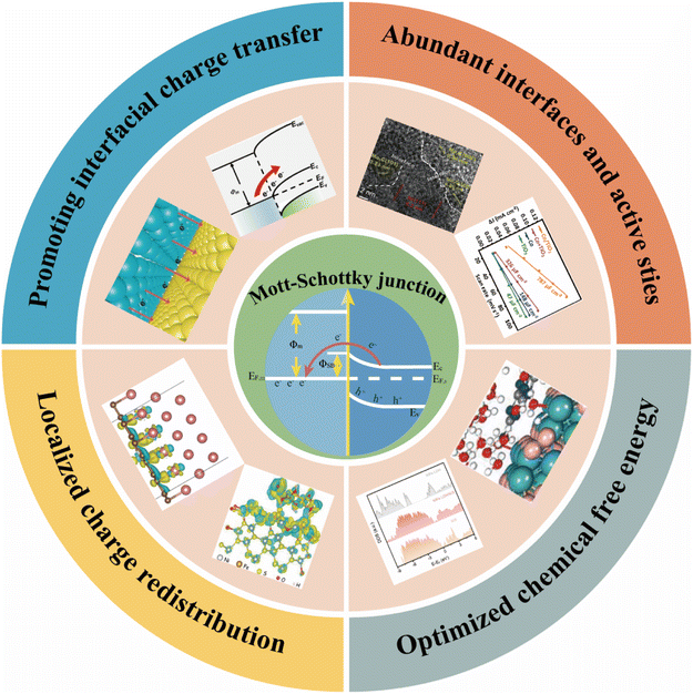 |
| | Scheme 1 Schematic illustration of the Mott–Schottky junction in electrocatalysts. | |
For the water-splitting process, the unique physicochemical properties of Mott–Schottky junctions could not only provide abundant active sites, but also promote both the adsorption and desorption processes of the OER and/or HER, thereby forming highly efficient Mott–Schottky electrocatalysts for water splitting. In this review, we will focus on the rational design of Mott–Schottky electrocatalysts and recent progress of the Mott–Schottky effect in water electrolysis. We specially review the strategies for preparing Mott–Schottky catalysts, and the relationships between the structure/composition and catalytic performance. Based on the discussions, several possible solutions and future directions are provided finally. We hope that this review could provide helpful guidance for developing cost-effective and highly efficient Mott–Schottky water-splitting electrocatalysts.
2. Metal/semiconductor contact induced Mott–Schottky junction
2.1 Construction of the Mott–Schottky junction
A Mott–Schottky junction is the interface region formed at the contact interface between a metal and semiconductor.63 For example in metal/n-type semiconductor, after stacking or stitching a metal with a semiconductor, the difference in work functions (ϕ) drives free electron transfer at the interface between the metal and semiconductor, followed by Mott–Schottky junction formation at the metal/semiconductor interface (Fig. 1).66 The ϕ is the minimum energy needed to extract an electron from a material at 0 K.67 As shown on the left of Fig. 1, when the n-type semiconductor work function (ϕs) < the metal work function (ϕm), the electrons will transfer from the semiconductor to the metal until the Fermi level of the semiconductor (EF,s) and metal (EF,m) is the same, followed by band bending and the formation of a Schottky barrier (ϕSB). The ϕSB allows the charges to irreversibly transport across the heterointerface, thus resulting in charge accumulation or depletion along the contact interface.68 In this case, the metal/semiconductor contact can induce a charged interface, with an enriched electron density on the metal side, while the semiconductor side is positively charged because of the electrostatic induction. As compared with the corresponding bulk, the electrons are depleted near the semiconductor surface, which is called the depletion layer. As shown on the right of Fig. 1, when ϕs > ϕm, the electrons will transfer from the metal to the semiconductor leading to the accumulation of the electrons near the semiconductor surface and thus forming an accumulation layer. Generally, when EF,m is below EF,s, the free charge will flow to the contacted metal side and thus causing the EF,s to decrease, and vice versa. It can be seen from the above that the Mott–Schottky junction can rectify the surface charge density at metal/semiconductor interfaces, which is described as the Mott–Schottky effect in state physics. Therefore, it can be expected that the adsorption of reaction intermediates and electron transport process will be affected by the charged contact interfaces.
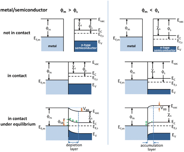 |
| | Fig. 1 Energy band diagrams of typical n-type semiconductor and metal contacts. ϕ, work function; χs, electron affinity of the semiconductor; EF, Fermi level; Evac, vacuum energy; Ec, conduction band; Ev, valence band. Reproduced with permission.66 Copyright 2012, American Chemical Society. | |
2.2 The effects of the Mott–Schottky junction for electrocatalysis
2.2.1 The effect on the interfacial electronic structure.
As mentioned above, electrocatalytic reactions including both the OER and HER take place on the surface and/or at the interface of the corresponding electrocatalysts. Therefore, the catalytic ability of electrocatalysts is dependent on the surface electronic structure and atomic arrangements.69 In order to improve their catalytic performance, it is of significance to modulate the surface charge distribution of the catalyst via rational structural design. In this regard, the built-in electric field at the Mott–Schottky junction can drive charge transfer along the interface and thus lead to charge redistribution on the surface structure, which is an effective method to accelerate electron transport from the surface of the catalyst to the reaction intermediate.70,71 The promoted electron transfer and abundant active sites synergistically lead to better electrocatalytic performance. For example, the Sun group designed a typical Co@NC heterostructure as a model Mott–Schottky catalyst for lithium–sulfur batteries by a metal–organic framework-templated method (Fig. 2).72 Experimental and theoretical investigations revealed the charge density redistribution and a built-in electric field at the heterointerface of Co@NC, which promoted Li+/e− transport and improved the kinetics of polysulfide reduction and Li2S oxidation in Li–S electrochemistry. With similar considerations in mind, the Cabot group dispersed metallic CoFeP on n-type C3N4 tubes (t-CN) to construct a Mott–Schottky catalyst for lithium–sulfur batteries by an electrostatic self-assembly method.73 The authors claimed that the optimized electronic structure and charge redistribution at the Mott–Schottky interface contributed to its superior rate performance. Undoubtedly, the electron redistribution at the metal/semiconductor interface via the Mott–Schottky effect can also facilitate the electrocatalytic reactions of the HER and/or OER. For example, Yang et al. encapsulated a Co/Co2P Mott–Schottky junction in N,P-doped carbon nanotubes as a Mott–Schottky electrocatalyst for bifunctional oxygen electrocatalysis.74 DFT calculations confirmed the facile electron transfer from metallic Co to semiconductive Co2P, upshifting the d-band center of Co/Co2P and thus enhancing its catalytic performance toward oxygen electrocatalysis.
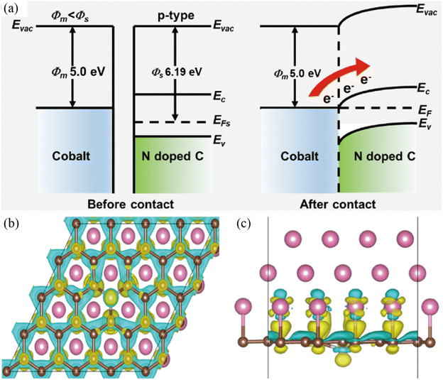 |
| | Fig. 2 (a) Energy band diagrams of Co and NC before and after the Mott–Schottky type contact. (b and c) Differential charge density redistributions at the interface between Co and NC. Yellow represents charge accumulation, while blue represents charge depletion. Reproduced with permission.72 Copyright 2021, American Chemical Society. | |
2.2.2 The effect on chemical free energy.
The electrocatalytic reaction including both the HER and OER can be concluded to proceed by the initial adsorption of the reactant, followed by the formation of reaction intermediates and the final desorption step.12,75 Based on the Sabatier principle, the binding between the reaction species and the active sites should be neither too strong nor too weak.76,77 Therefore, to achieve higher activity, the chemisorption and desorption free energy of the electrocatalysts should be optimized. Recently, the construction of a Mott–Schottky junction has been explored to tune the chemisorption and desorption behaviors of the electrocatalysts to enhance their inherent activities toward electrocatalytic reactions.78–80 For example, Yuan et al. constructed Mott–Schottky Bi–BiVO4 heterostructures for electrochemical urea synthesis by a NaBH4 reduction method.81 DFT calculations revealed that the targeted adsorption of N2 and CO2 were facilitated through the formed space-charge region at the Bi–BiVO4 interface (Fig. 3a and b). In addition, the space-charge region could also activate N2 and CO2 molecules and optimize the Gibbs free energy of the corresponding reaction intermediates (Fig. 3c). Benefitting from the Mott–Schottky effect, the Bi–BiVO4 electrocatalyst exhibited an improved urea yield rate and faradaic efficiency. Sun et al. designed Mott–Schottky Mo–MoS2 heterojunctions as an efficient electrocatalyst for the HER under all pH conditions by an in situ lithiation method.82 The authors claimed that the heterointerfaces of Mo–MoS2 not only resulted in the electron redistribution of sulfur sites, but also facilitated the proton and H2O adsorption, leading to an enhanced HER activity over the whole pH range.
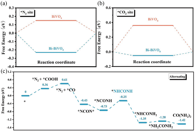 |
| | Fig. 3 DFT-calculated adsorption energies for (a) N2 and (b) CO2 on pristine BiVO4 and Bi–BiVO4. (c) Energetic pathway of electrolytic urea production. Reproduced with permission.81 Copyright 2018, Wiley-VCH. | |
To sum up, the rational combination of a semiconductor and metal to build a delicate Mott–Schottky junction in electrocatalysts can significantly improve the catalytic reactivity of the electrocatalysts. The constructed Mott–Schottky junction could not only adjust the charge densities of atoms near the interface, but also optimize the reaction kinetics, thus showing enhanced activity toward specific catalytic reactions.65,83 With these considerations, rational integration of a semiconductor and metal to construct a delicate Mott–Schottky catalyst is a proof-of concept strategy for designing efficient earth-abundant HER/OER electrocatalysts, because the charged surfaces in Mott–Schottky catalysts have important influence on the charge transfer process and absorption of ions involved in the HER and OER. Research on Mott–Schottky catalysts toward water electrolysis is a rapidly emerging research focus and recent research efforts have triggered excellent syntheses and electrochemical application of Mott–Schottky catalysts in the water splitting reaction (Table 1). In this review, we discuss recent significant advances in developing Mott–Schottky electrocatalysts in the electrochemical water splitting application, along with the underlying mechanisms. Based on the discussions, some challenges and future directions about Mott–Schottky electrocatalysts are provided.
Table 1 Mott–Schottky electrocatalysts for the HER and OER, respectively
| Mott–Schottky catalyst |
Application |
Electrolyte |
η
10 (mV) |
Tafel slope (mV dec−1) |
Ref. |
| MoB/g-C3N4 |
HER |
1 M KOH |
133 |
46 |
63
|
| MoC/NPC@CNTs |
HER |
0.5 M H2SO4 |
175 |
62 |
91
|
| FeNi/DCF/NC |
HER |
1 M KOH |
169 |
98 |
92
|
| Co/TiO2 |
HER |
1 M KOH |
229 |
88 |
93
|
| Co@CoMoO4 |
HER |
1 M KOH |
46 |
85 |
94
|
| Co/a-WOx |
HER |
1 M KOH |
36.3 |
53.9 |
95
|
| Co/Co2P@NPCNTs |
HER |
1 M KOH |
310 |
71.5 |
74
|
| NiFe LDH/NiS |
OER |
1 M KOH |
230 |
110.7 |
100
|
| Co/Co3O4@N-CNTs |
OER |
1 M KOH |
275 |
99.2 |
101
|
| Co2P2O7@N,P–C |
OER |
1 M KOH |
270 |
49.1 |
104
|
| Co/CoSe@NC |
OER |
1 M KOH |
335 |
77.6 |
106
|
| Ni/Ni0.2Mo0.8N@N–C |
OER |
1 M KOH |
260 |
46 |
108
|
3. Properties of Mott–Schottky catalysts for water electrolysis
3.1 Hydrogen evolution reaction
3.1.1 Brief introduction of the HER mechanism.
The HER is a two-electron transfer reaction and may proceed through the Volmer–Heyrovsky or the Volmer–Tafel pathway, which is roughly discerned from the Tafel slope:84,85
Volmer step (Tafel slope = 120 mV dec−1):
| H+ + * + e− → H* (in acidic medium) |
| H2O + * + e− → H* + OH− (in basic medium) |
Heyrovsky step (Tafel slope = 40 mV dec−1):
| H* + H+ + e− → H2 + * (in acidic medium) |
| H* + H2O + e− → H2 + OH− + * (in basic medium) |
Tafel step (Tafel slope = 30 mV dec−1):
where * denotes an active site and H* is the catalytic intermediate of the adsorbed hydrogen atom. The reaction rate of the HER is largely determined by the Gibbs free energy of hydrogen adsorption (Δ
GH). When Δ
GH is more positive, in other words, the electrocatalyst surface adsorbs hydrogen too weakly, and the Volmer step (the adsorption step) will be the rate determining step. However, if the adsorption is too strong, the Heyrovsky/Tafel step (the desorption step) will be the rate determining step. Therefore, the highly active electrocatalysts towards the HER should adsorb hydrogen neither too weakly nor too strongly. As shown in the Volcano plot (
Fig. 4), noble-metal-based electrocatalysts with a near-zero Δ
GH may occupy the top of the volcano, that is to say, they will display the highest catalytic activity for the HER.
86 It is worth noting that most HER electrocatalysts exhibit much lower activity in basic solutions than that in acidic medium.
87,88 Strmcnik
et al. attributed the poor catalytic performance of alkaline HER catalysts to the sluggish water dissociation process in alkaline medium.
89 To evaluate the performance of a HER electrocatalyst, the corresponding parameters should be accurately measured or calculated, for instance, overpotential, Tafel plot, turnover frequency (TOF), faradaic efficiency and stability. Significantly, the catalytic activity of a HER electrocatalyst is related to the electronic structure and adsorption energy of the surface active sites.
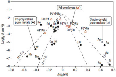 |
| | Fig. 4 Volcano plots of various metals towards the HER. Reproduced with permission.86 Copyright 2016, Springer Nature. | |
As mentioned above, the optimal HER catalyst always has a ΔGH close to zero. In this regard, constructing a Mott–Schottky junction may help to modify the surface electronic structures and optimize the adsorption energy of the electrocatalyst, facilitating the HER kinetics. In addition, by constructing a Mott–Schottky junction, the interfacial electron transfer can also be accelerated, further enhancing the HER activity of the electrocatalyst. The Mott–Schottky effect has been demonstrated as a very promising way to boost the activity of electrocatalysts for specific catalytic reactions and extended to rationally designing Mott–Schottky electrocatalysts for the HER.
3.1.2 Mott–Schottky catalysts for the HER.
2D carbonaceous materials, such as g-C3N4 and heteroatom doped carbon materials, could serve as the semiconductor side for the construction of Mott–Schottky catalysts. Zhuang and coworkers reported a MoB/g-C3N4 Mott–Schottky catalyst by simply blending tetragonal α-MoB with n-type g-C3N4 (Fig. 5a–e).63 A temperature-dependent resistivity test and local density of states (DOS) analysis showed that the tetragonal α-MoB exhibited metallic characteristics. UV/vis analysis suggested that n-type g-C3N4 possessed a wide band gap of 2.7 eV, making it suitable for Mott–Schottky contact formation. As shown in Fig. 5b, the MoB/g-C3N4 Mott–Schottky catalyst exhibited better HER catalytic activity than MoB in 1 M KOH, indicating the role of the Mott–Schottky contact in boosting the HER activity of MoB/g-C3N4. X-ray photoelectron spectroscopy (XPS) and energy-loss near-edge structure (ELNES) measurements are conducted to unravel the electronic structures of MoB/g-C3N4 (Fig. 5c and d). These results confirmed that the local electron density of Mo atoms in MoB/g-C3N4 increased (donated by g-C3N4), indicating that the Mott–Schottky effect could create a fraction of Mo atoms in MoB/g-C3N4 in a reduced state. It should be noted that photoluminescence (PL) together with ultraviolet photoemission spectroscopy (UPS) analyses validated the existing Mott–Schottky effect. Benefiting from the increased local electron density of MoB and efficient charge transfer across the MoB/g-C3N4 Mott–Schottky junction, the kinetic reaction barriers of the HER process on the Mott–Schottky catalyst were dramatically reduced (Fig. 5e). Moreover, MoB/g-C3N4 demonstrated stability for > 48 h at 10 mA cm−2 and exhibited negligible attenuation after 5000 cycles, indicating its excellent stability for the HER. In addition, Xia et al. developed a MoN/g-C3N4 Mott–Schottky catalyst by a self-assembly and annealing method, which showed an enhanced catalytic activity towards photocatalytic H2 production.90
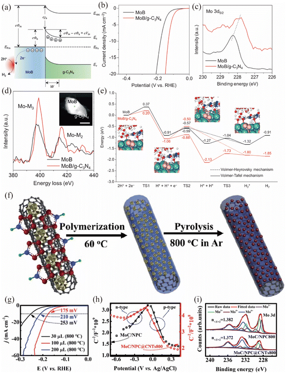 |
| | Fig. 5 (a) Energy band diagrams of the Schottky junction between MoB and g-C3N4. (b) Polarization curves of MoB and MoB/g-C3N4 in 1 M KOH. (c) XPS spectra of Mo 3d5/2 and (d) ELNES of Mo-M2,3 edges for MoB in comparison with MoB/g-C3N4. (e) Free energy diagram of the HER on MoB and MoB/g-C3N4. Reproduced with permission.63 Copyright 2018, Wiley-VCH. (f) The preparation procedure for the synthesis of MoC/NPC@CNTs. (g) LSV curves of MoC/NPC@CNTs with different pyrrole amounts in 0.5 M H2SO4. (h) Mott–Schottky plots for MoC/NPC800 and MoC/NPC@CNTs800. (i) XPS spectra of Mo 3d for MoC/NPC800 and MoC/NPC@CNTs800. Reproduced with permission.91 Copyright 2020, Royal Society of Chemistry. | |
Wang et al. prepared a MoC based Mott–Schottky catalyst by carbonization of polyoxometalates and polypyrrole nanocomposites (Fig. 5f).91 The MoC nanoparticles were uniformly embedded in N,P co-doped carbon and further covered on the carbon nanotubes (CNTs), constructing a MoC/NPC@CNT Mott–Schottky electrocatalyst. The optimal MoC/NPC@CNTs showed excellent HER performance with a small overpotential (η) of 175 mV to reach a current density of 10 mA cm−2 in 0.5 M H2SO4 (Fig. 5g). Based on the small positive slope of Mott–Schottky plots in Fig. 5h and Hall results, the authors claimed that the Mott–Schottky effect existed between N,P co-doped carbon and metallic MoC. Notably, the introduced CNTs could further increase the electron density around Ef, due to its impact on facilitating the electron transfer from carbon to MoC. As shown in Fig. 5i, the XPS results indicated that the Mo3+/Mo2+ ratio in MoC/NPC (1.382) or MoC/NPC@CNTs (1.372) was far lower than that of pure MoC (10.9). The smaller Mo3+/Mo2+ ratio caused by the Mott–Schottky effect could modulate Mo–H bond strength for optimal ΔGH, accelerating the Volmer reaction step and thus enhancing the HER activity. In addition, the optimized MoC/NPC@CNTs was stable for 12 h at 10 mA cm−2 and the deviation after 1000 cyclic voltammetric (CV) scans was negligible. Similarly, Wang et al. prepared a Mott–Schottky catalyst based on metallic FeNi/defect-rich CoFe2O4 decorated on semiconducting nitrogen-doped carbon,92 which boosts the charge transfer ability of transition metal oxides and provides a promising way to enhance the HER activity of oxides in an alkaline environment.
Besides, metal oxides have been explored as the semiconductor side for the construction of Mott–Schottky catalysts for the HER as well. Yu and co-workers succeeded in dispersing TiO2 nanoparticles on the surface of microscale Co dendrites by a one-pot hydrothermal method (Fig. 6a), constructing a Co/TiO2 Mott–Schottky catalyst.93 The high-resolution TEM and inverse fast Fourier transform (FFT) images presented the interfacial structure between Co and TiO2 (Fig. 6b). DOS plots of the d-orbital and total orbital showed that Co/TiO2 had a negative shift of the d-band center and higher electron density than Co (Fig. 6c and d). The planar-averaged electron density difference on Co/TiO2 (Fig. 6e), together with XPS analysis indicated that the free electrons would flow from TiO2 to Co, confirming the formation of a Mott–Schottky junction. DFT calculations showed that the Mott–Schottky junction in Co/TiO2 could effectively optimize the ΔGH and thus increase the HER catalytic activity (Fig. 6f). As a result, the as-prepared Co/TiO2 Mott–Schottky catalyst displayed superior HER catalytic activity with an η of 229 mV to deliver a current density of 10 mA cm−2 and a TOF of 0.052 s−1 in 1 M KOH (Fig. 6g). Additionally, the Co/TiO2 Mott–Schottky catalyst displayed excellent stability, as evidenced by the results of accelerated degradation tests (ADTs) and chronopotentiometric measurements. In another study, Xiang et al. successfully prepared a self-standing Co@CoMoO4 catalyst by calcination of cobalt carbonate hydroxide@CoMoO4.94 The positive shift of the binding energies of Co 2p and Mo 3d indicated the possible construction of a Mott–Schottky junction between metallic Co and n-type CoMoO4. Benefiting from the synergistic effect, the resulting Co@CoMoO4 catalyst afforded a current density of 10 mA cm−2 at an extremely low overpotential of 46 mV in 1 M KOH. Most recently, Chen and co-workers reported a Co/a-WOx Mott–Schottky electrocatalyst with a hollow porous nanowire structure through a self-template etching method.95 The porous tubular structure exposed abundant heterointerfaces, maximizing the Mott–Schottky effect. Experimental and theoretical investigations demonstrated facile electron transfer and redistribution across the heterointerface, which endowed the Co nanoparticles with the properties of accelerating water dissociation and a-WOx with optimized adsorption energy for hydrogen intermediates. Benefitting from maximizing the Mott–Schottky effect and the unique nanostructure, Co/a-WOx showed superior alkaline HER activity with a small overpotential of 36.3 mV to acquire 10 mA cm−2 and a low Tafel slope (53.9 mV dec−1) as well as stability for 200 h in 1 M KOH.
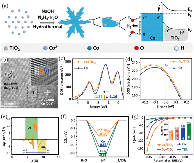 |
| | Fig. 6 (a) Illustration of the preparation and HER procedure of the Co/TiO2 Mott–Schottky catalyst. (b) HRTEM image of Co/TiO2. Inset shows the inverse FFT in region II. DOS plots of the d-orbital (c) and total orbital contribution to Co and Co/TiO2 (d). (e) The difference of planar-averaged electron density for the Co/TiO2 Mott–Schottky catalyst. (f) ΔGH* of various samples. (g) LSV curves of various samples. Reproduced with permission.93 Copyright 2019, American Chemical Society. | |
3.2 Oxygen evolution reaction
3.2.1 Brief introduction of the OER mechanism.
Compared with the HER, the OER is a complicated 4-electron process along with the adsorption of various oxygen intermediates, leading to more sluggish kinetics. Thus, a large η is needed to initiate the OER, making it the bottleneck for the water splitting reaction. The four-electron reaction pathway in acidic medium has been proposed as follows:96,97
| O* + H2O → H+ + HOO* + e− |
Under basic conditions, the four-step process of the OER is described as follows:
| HO* + OH− → H2O + O* + e− |
| OH− + HOO* → * + H2O + O2 + e− |
where * denotes an active site, while HO*, O* and HOO* represent the oxygen-containing absorption intermediates. Unlike the HER, the binding energies of the three important intermediates are strongly correlated. As proposed by previously reported articles,
97,98 a scaling relationship between the binding energies of adsorbed HOO* and HO* intermediates (Δ
GOOH = Δ
GOH + 3.2 ± 0.2 eV) is screened theoretically (
Fig. 7a). Take the overall energy barrier of 4.92 eV into consideration, this scaling relationship indicates that the rate-determining step is probably the formation of O* (step 2) or HOO* (step 3) with a minimized Gibbs free energy of ≈1.6 eV. An optimal OER catalyst should bind the key oxygen adsorbate neither too strongly nor too weakly on the basis of the Sabatier principle.
76 Therefore, the difference (Δ
GO* − Δ
GHO*) is commonly regarded as an effective descriptor to evaluate the catalytic activity of catalysts and is translated to the OER volcano plot (
Fig. 7b). As shown in the OER volcano plot, noble-metal-based electrocatalysts (RuO
2) with a moderate bonding energy of oxygen intermediates will show the highest catalytic activity toward the OER. Similar to the HER, the Mott–Schottky effect is also a very promising strategy for optimizing the binding energies of oxygen intermediates to facilitate the kinetics of the OER.
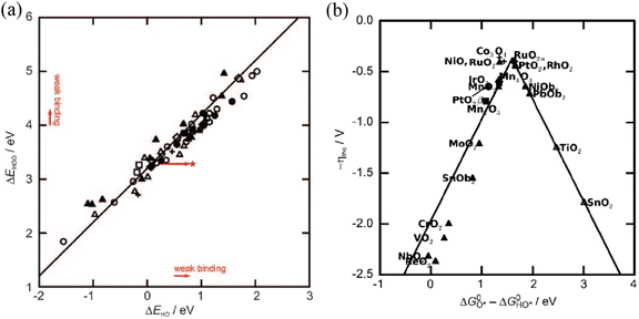 |
| | Fig. 7 (a) The scaling relationship between the binding energies of adsorbed HOO* and HO* intermediates on various metal oxides. (b) OER volcano plot for metal oxides against GO* − GHO*. Reproduced with permission.97 Copyright 2011, Wiley-VCH. | |
3.2.2 Mott–Schottky catalysts for the OER.
Metal (oxy)hydroxides, oxides and LDHs have been actively investigated as the semiconductor side for the synthesis of Mott–Schottky catalysts for the OER.99–103 Wen et al. prepared a NiFe LDH/NiS Mott–Schottky catalyst by electrodepositing NiFe LDH onto NiS nanosheets (Fig. 8a–f).100 The total densities of states (TDOS) proved that NiS was metallic, while NiFe LDH exhibited semiconductor characteristics with a band gap of 1.51 eV (Fig. 8c). The NiFe LDH/NiS contact induced an active interface region (Mott–Schottky junction), where the electrons will transfer from metallic NiS to semiconductive NiFe LDH as revealed by DFT calculations (Fig. 8d and e) and XPS. Furthermore, the d-band center of Ni (Fe) atoms near the Mott–Schottky junction shifted to a high energy level, resulting in the optimal binding energy of oxygen-containing intermediates. Benefitting from the interfacial charge redistribution of the Mott–Schottky junction and porous hierarchical structure, the resultant NiFe LDH/NiS Mott–Schottky catalyst exhibited impressive OER performance with a low η10 and η1000 of 230 and 325 mV (Fig. 8f), respectively. Additionally, NiFe LDH/NiS possessed an excellent stability with negligible potential decay for over 100 h of a continuous test at 400 mA cm−2 in 1 M KOH. Similarly, the Li group reported a NiFe(OH)x/Ni3S2 Mott–Schottky junction by in situ assembly of a NiFe(OH)x electrocatalyst onto the as-prepared Ni3S2 layer supported on a Ni mesh,99 and revealed the charge redistribution at the interface between NiFe(OH)x and Ni3S2. Thus, the resultant NiFe(OH)x/Ni3S2/Ni electrode showed extraordinary OER performance in 1 M KOH.
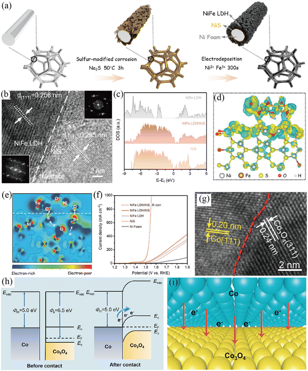 |
| | Fig. 8 (a) Illustration of the preparation of NiFe LDH/NiS. (b) HRTEM image and corresponding FFT patterns of NiFe LDH/NiS. (c) The calculated total density of states (TDOS) for various samples. (d) Charge density difference and (e) corresponding 2D data plot for the NiFe LDH/NiS model. (f) LSV curves of different electrodes. Reproduced with permission.100 Copyright 2021, Wiley-VCH. (g) HRTEM image of Co/Co3O4@N-CNTs. (h) Energy band diagrams of Co3O4 and Co. (i) Illustration of the interfacial charge transfer between Co3O4 and Co. Reproduced with permission.101 Copyright 2022, Elsevier B. V. | |
Co/Co3O4 Mott–Schottky heteronanoparticles embedded in N-doped carbon nanotubes (Co/Co3O4@N-CNTs) were successfully synthesized by a hydrogel-bridged pyrolysis strategy (Fig. 8g–i).101 The high resolution transmission electron microscopy (HRTEM) image of Co/Co3O4 heteronanoparticles exhibited the interface between Co3O4 and Co (Fig. 8g), verifying the construction of Mott–Schottky interfaces. According to energy band diagrams (Fig. 8h), the work function of metallic Co (5.0 eV) was lower than that of semiconductive Co3O4 (6.5 eV). Thus, a built-in electric field was generated in the Co/Co3O4 heteronanoparticles, which would drive the electron transfer from the metallic Co side to the semiconductive Co3O4 side until reaching equilibrium Fermi levels (Fig. 6i). DFT calculation results together with XPS analysis further demonstrated the above charge redistribution across the interface between Co and Co3O4. Such charge redistribution can energetically help the adsorption of oxygen intermediates and reduce the overpotentials for the OER and ORR. Regarding the OER, the as-prepared Co/Co3O4@N-CNTs showed a lower overpotential and smaller Tafel plot than other contrast samples in 1 M KOH. In addition, the N-doped carbon nanotube (N-CNT) shell could expose more active components, enhance electron transfer efficiency and protect the anchored active sites, further boosting the activity and stability of Co/Co3O4@N-CNTs. With similar considerations in mind, Co/CoOx Mott–Schottky junctions were embedded in BS-NCNTs to prepare a bifunctional Co/CoOx@BS-NCNT electrocatalyst by a template-free self-assembly method,103 which exhibited enhanced activities towards the OER and ORR.
Other transition metal based semiconductors, such as transition metal nitrides, phosphides, chalcogenides and pyrophosphate, were also explored as a matrix to construct a Mott–Schottky junction as well.104–108 Liang and co-workers prepared Co2P2O7@N,P–C nanocages by a ligand exchange reaction and subsequent pyrolysis process (Fig. 9a–e).104 The HRTEM image showed the contact interface between Co2P2O7 and N, P co-doped carbon (N,P–C) (Fig. 9a). A temperature-dependent resistivity test demonstrated the metallic characteristics of N,P–C, as also confirmed by the XPS valence band spectrum. Thus, a Mott–Schottky junction is constructed between semiconductive Co2P2O7 and metallic N,P–C based on the theory of semiconductor physics, in which a built-in electric field was formed. On the basis of UPS results, the work function of metallic N,P–C (5.2 eV) was higher than that of semiconductive Co2P2O7 (3.8 eV) (Fig. 9b). Therefore, the valence electrons will transfer from Co2P2O7 NPs to the N,P–C layer until the Fermi levels reach equilibrium driven by the built-in electric field (Fig. 9c), which was also proved by XPS and FT-IR analysis. In this case, the valence electron density of Co can be remarkably reduced, thereby optimizing its occupancy of the eg orbital and then contributing to the adsorption energies of oxygen intermediates (Fig. 9d). On account of the enhanced intrinsic catalytic activity caused by the interfacial charge polarization of the Mott–Schottky junction, Co2P2O7@N,P–C exhibited an extraordinary OER performance with a very high turnover frequency value and low overpotential in basic medium. In addition, the resultant Co2P2O7@N,P–C electrocatalyst showed outstanding catalytic stability towards the OER with no obvious overpotential increase after a 100 h chronopotentiometry (CP) test, owing to the protection of the robust N,P–C layer.
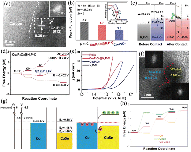 |
| | Fig. 9 (a) HRTEM image of the as-prepared Co2P2O7@N,P–C nanocage catalyst. (b) Work function values of various samples (inset: corresponding UPS spectra). (c) Energy band diagrams of Co2P2O7 and N,P–C before and after the construction of the Mott–Schottky heterojunction. (d) Free energy diagram of Co2P2O7@N,P–C for the OER. (e) The OER LSV curves of different samples. Reproduced with permission.104 Copyright 2019, Elsevier B. V. (f) HRTEM image with FFT patterns (inset) of Co/CoSe@NC. (g) Schematic energy band diagrams of Co and CoSe before and after forming a Schottky contact. (h) Free energy diagrams of CoSe, Co and Co/CoSe for the OER. Reproduced with permission.106 Copyright 2022, Elsevier B. V. | |
Li and co-workers constructed a Co/CoSe Mott–Schottky junction encapsulated in N-doped carbon by an in situ partial reduction strategy.106 The in situ partial reduction of CoSe to Co ensured a close contact interface between metallic Co and semiconductive CoSe, which was directly visualized by the HRTEM image and corresponding FFT patterns (Fig. 9f). According to Mott–Schottky and Tauc plots, the energy band diagrams of the Co/CoSe Mott–Schottky junction were proposed (Fig. 9g). The lower Fermi levels of semiconductive CoSe than that of metallic Co resulted in electron transfer from Co to CoSe, which was verified by XPS analysis and DFT calculations. Consequently, a Mott–Schottky heterojunction is constructed and interfacial charge polarization is created, thus leading to a hole abundant region on the metallic side. DFT calculations revealed that the hole-rich Co center in the Co/CoSe Mott–Schottky junction possessed strong oxidation capacity, which is conducive to the OER (Fig. 9h). Because of the charge redistribution of the Mott–Schottky junction and the mesoporous carbon encapsulation, the as-prepared Co/CoSe@NC showed superior OER and ORR performance in alkaline media. Focusing on this topic, the Huang group designed a Co9S8/Co Mott–Schottky junction supported on defective reduced graphene oxide (Co9S8/Co-rGO) as a bifunctional oxygen catalyst (OER and ORR).105 The constructed Co9S8/Co Mott–Schottky junction is conducive to the adsorption of oxygen intermediates towards catalyzing OER and ORR processes. Benefiting from the charge density redistribution across the Mott–Schottky junction and optimized oxygen/ion diffusion pathways, the as-formed Mott–Schottky Co9S8/Co–rGO catalyst exhibits enhanced catalytic activity towards the OER and ORR with a facile reaction mechanism.
Li et al. developed a hard-template strategy to successfully synthesize Mott–Schottky Ni/Ni0.2Mo0.8N nanosheets combined with N-doped carbon (Ni/Ni0.2Mo0.8N@N–C).108 The authors claim that the Mott–Schottky Ni/Ni0.2Mo0.8N nanosheets provide a highway for charge transfer and reaction-relevant species, which will contribute to the generation of Oads intermediates and thus promote the subsequent OER step. Moreover, the carbon frameworks not only optimize the electron transportation, but also prevent the agglomeration of Ni/Ni0.2Mo0.8N nanosheets. Besides, the N dopants modulate the electronic structures of carbon that favor the OER process. As a result, the as-obtained Ni/Ni0.2Mo0.8N@N–C exhibits excellent OER catalytic activity and stability, with a low η10 of 260 mV and a negligible attenuation after 2000 CV cycles in 1 M KOH. The excellent structural stability of Ni/Ni0.2Mo0.8N@N–C was corroborated by SEM and XPS characterization. Similarly, Chen and co-workers constructed Co/CoxMy (M = P, N) nanosheets as a Mott–Schottky catalyst for the OER through a salt-templated strategy.107 Benefiting from the Mott–Schottky components and hierarchically porous structure, the Co/CoxMy Mott–Schottky catalyst shows improved OER activity in alkaline medium.
3.3 Overall water splitting
3.3.1 Brief introduction of overall water splitting.
Up to now, various earth-abundant electrocatalysts have been reported for the OER in alkaline media and the HER in acidic electrolytes. However, in order to work together for water electrolysis, catalysts capable of catalyzing both the OER and HER must work in the same electrolyte. In addition, water electrolysis is always performed in either a strong alkali or an acid so as to simplify the water splitting system design and reduce the overpotentials.109,110 However, an earth-abundant electrocatalyst with high activity in alkali aqueous solution will probably be unstable or inactive in an acidic electrolyte. Therefore, it is of great significance to exploit highly efficient and stable bifunctional electrocatalysts for overall water splitting. Integrating the virtues of the OER and HER catalysts is an effective way to design highly efficient HER–OER heterostructures,111–114 which can possess optimized adsorption energy for both oxygen and hydrogen intermediates, thus enhancing the catalytic activity of overall water splitting. This stimulates the investigation of Mott–Schottky junction electrocatalysts capable of catalyzing both the OER and HER (Table 2). Here, we summarize the recent advances in Mott–Schottky junction based bifunctional water splitting electrocatalysts with an emphasis on their rational design, structural characterization, and catalytic activity.
Table 2 Mott–Schottky electrocatalysts for overall water splitting
| Mott–Schottky catalyst |
Electrolyte |
Current density |
Overall voltage |
Ref. |
| Co/CoP-5/Ni foam |
1 M KOH |
10 mA cm−2 |
1.45 V |
115
|
| NC/CuCo/CuCoOx |
1 M KOH |
10 mA cm−2 |
1.53 V |
116
|
| RuO2/Co3O4–RuCo@NC |
0.5 M H2SO4 |
10 mA cm−2 |
1.66 V |
117
|
| Ni–Mo2C/NC@NF |
1 M KOH |
10 mA cm−2 |
1.59 V |
118
|
| Co–Mo2C-CNx |
1 M KOH |
10 mA cm−2 |
1.68 V |
119
|
| WN-Ni@N,P-CNT |
1 M KOH |
10 mA cm−2 |
1.57 V |
121
|
| Ni/CeO2@N–CNFS |
1 M KOH |
10 mA cm−2 |
1.56 V |
122
|
3.3.2 Mott–Schottky catalysts for overall water splitting.
The integration of a transition-metal-based metal and semiconductor to construct a Mott–Schottky electrocatalyst is a proof-of-concept strategy to simultaneously catalyze both the OER and HER by means of the Mott–Schottky effect. Considering the highly catalytic activity of Co and CoP catalysts for the HER in both an alkali and an acid, the Li group developed Mott–Schottky Co/CoP nanoparticles as catalysts toward both the OER and HER in a wide pH range by a vacuum-diffusion method (Fig. 10a–e).115 By combining energy-dispersive X-ray spectroscopy line scan with HRTEM results (Fig. 10b and c), the formation of Co/CoP-5 nanoparticles was efficiently identified. The work function of semiconductive CoP was lower than that of Co, and thus electrons would transfer from semiconductive CoP to metallic Co due to the Mott–Schottky effect (Fig. 10e), which was directly verified by XPS analysis (Fig. 10d). The authors claimed that the electron redistribution at the interface would lower the work function of the Co “facet” and pull down the valence band of the CoP “facet”, resulting in the improved HER and OER activity of the Co/CoP Mott–Schottky electrocatalyst in a wide pH range, respectively. In addition, Co/CoP-5 showed a minimal potential decay after a 12 h stability test (a 10 mV increase of overpotential at 20 mA cm−2 in 1 M KOH).
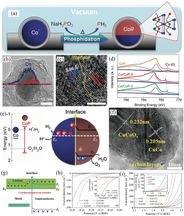 |
| | Fig. 10 (a) Synthetic process of carbon coated Co/CoP-5. (b) Compositional line profile of Janus Co/CoP-5. (c) HRTEM image of Janus Co/CoP-5. (d) Co 2p XPS spectra of various samples. (e) Energy band diagrams of Co and CoP before and after forming a Mott–Schottky contact. Reproduced with permission.115 Copyright 2017, Wiley-VCH. (f) TEM image of NC/CuCo/CuCoOx nanowires. (g) Continuous charge transfer of the Mott–Schottky catalysts. (h) HER polarization curves of different samples. (i) OER polarization curves of various samples. Reproduced with permission.116 Copyright 2017, Wiley-VCH. | |
Afterwards, Hou and co-workers reported a NC/CuCo/CuCoOx Mott–Schottky electrocatalyst by implanting nitrogen-doped carbon (NC) on a metal (CuCo)–semiconductor (CuCoOx) nanowire array (Fig. 10f–i).116 In NC/CuCo/CuCoOx, CuCo nanocrystals were dispersed on CuCoOx nanowires, which were encapsulated by ultrathin NC shells with a thickness of ≈5 nm. The ultrathin NC shell could serve as a highway for continuous charge transfer between CuCo and CuCoOx (Fig. 10g). NC/CuCo/CuCoOx presented a small overpotential of 112 and 198 mV at a current density of 10 mA cm−2 for the HER and OER in 1 M KOH (Fig. 10h and i), respectively. The as-assembled NC/CuCo/CuCoOx‖NC/CuCo/CuCoOx cell needed a voltage of just 1.53 V to reach a current density of 10 mA m−2 for overall water splitting and the high activity was still maintained after 100 h of electrolysis. The authors proposed that the 3D hierarchical architectures, Mott–Schottky effect and nitrogen-doped carbon were responsible for the enhanced activities of NC/CuCo/CuCoO for the HER and OER.
To further explore the role of the Mott–Schottky effect in enhancing the activities of overall water splitting, various heteroatom-doped carbon confined Mott–Schottky electrocatalysts have been reported recently.117–121 The Shao group developed a Ru-modified cobalt-based Mott–Schottky catalyst embedded in an N-doped carbon support (RuO2/Co3O4–RuCo@NC) for overall water splitting in acidic media (Fig. 11a–g).117 The enlarged HRTEM image and corresponding FFT patterns revealed the existence of abundant interfaces (Fig. 11a–e). The Mott–Schottky interface would result in the redistribution of electrons at the interface between metallic RuCo and semiconductive RuO2/Co3O4 (Fig. 11f). Such an electron redistribution at the interface positively shifted the flat-band potential of RuO2/Co3O4–RuCo@NC to 2.33 V (Fig. 11g), indicating its more thermodynamically favorable OER process. Benefitting from the unique Mott–Schottky interfaces and favorable electron redistribution, the as-fabricated RuO2/Co3O4–RuCo@NC Mott–Schottky catalysts displayed excellent activities for both the OER and HER with a low overpotential and long-term stability in 0.5 M H2SO4. The RuO2/Co3O4–RuCo@NC electrolyzer required a cell voltage of 1.66 V to achieve 10 mA cm−2 for overall water splitting and exhibited long-term stability with ∼5% attenuation after an 8 h stability test at 10 mA cm−2 in 0.5 M H2SO4. Very recently, Xu et al. reported the large-area synthesis of Ni–Mo2C/NC@NF through an assembly carburization strategy.118 The as-prepared Ni–Mo2C/NC@NF Mott–Schottky catalyst could be used as a bifunctional electrode for overall water splitting with outstanding activity and stability in 1 M KOH solution, requiring a small HER and OER overpotential of 40 mV and 337 mV to reach a 10 mA cm−2 current density (Fig. 11h and i). The Ni–Mo2C/NC@NF cell needed small voltages of 1.59 and 1.80 V to gain 10 and 50 mA cm−2 for overall water electrolysis in 1 M KOH, respectively. In addition, Ni–Mo2C/NC@NF showed high stability with negligible current degradation for 150 h of continuous testing at 10 mA cm−2. DFT calculations validated that the construction of Mott–Schottky interfaces enables beneficial electronic structures for catalyzing both the HER and OER (Fig. 11j and k).
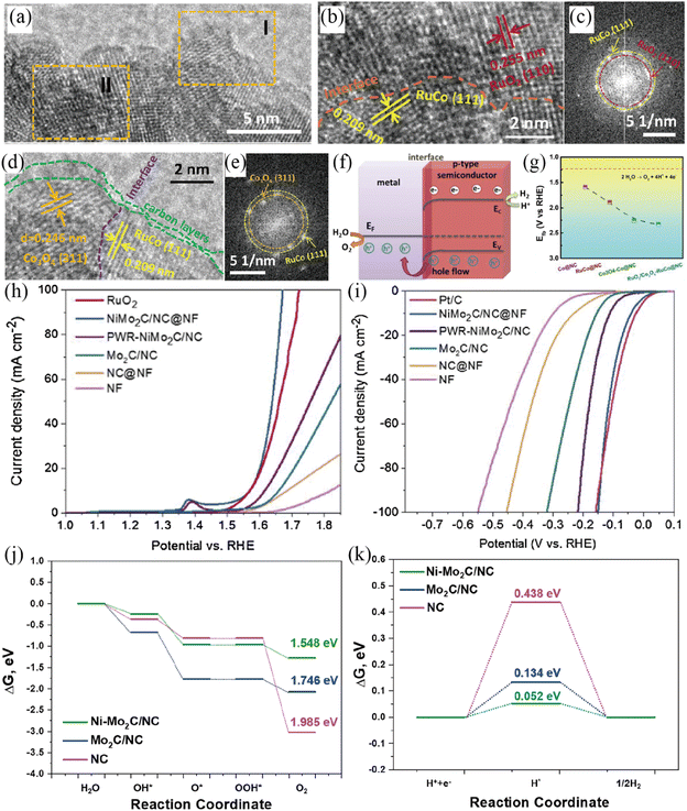 |
| | Fig. 11 (a) HRTEM image of RuO2/Co3O4–RuCo@NC. Enlarged HRTEM images in section I (b) and section II (d) and corresponding FFT patterns (c and e). (f) Energy band diagram of Mott–Schottky RuO2/Co3O4–RuCo@NC. (g) Flat-band position of different samples. Reproduced with permission.117 Copyright 2019, American Chemical Society. (h) Polarization curves of various samples for the OER in 1 M KOH solution. (i) Polarization curves of different samples for the HER in 1 M KOH solution. The free energy diagrams of NC, Mo2C/NC and Ni–Mo2C/NC for the OER (j) and HER (k). Reproduced with permission.118 Copyright 2021, Elsevier B. V. | |
With these considerations, Zhang and co-workers fabricated a dual Mott–Schottky electrocatalyst (Co–Mo2C-CNx) by the carbonization of Co–Zn MOF to wrap Co–Mo2C nanoparticles in porous nitrogen-doped carbon.119 The dual Mott–Schottky heterostructure of Co–Mo2C-CNx enabled the whole system present a metallic state, which was conducive to electron transfer. Moreover, the dual Mott–Schottky heterostructure will offer rich charge carriers for intermediate adsorption, thus accelerating the water adsorption/dissociation. The Yang group reported that an N,P co-doped CNT confined WN-Ni Mott–Schottky heterostructure (WN–Ni@N,P-CNT) could lead to enhanced HER and OER catalytic activity.121 In the Mott–Schottky heterogeneous electrocatalyst, the Mott–Schottky junction existing at the WN–Ni interface was beneficial to electron transfer and water dissociation, thereby promoting the overall water splitting. Subsequently, WN-Ni@N,P-CNT showed improved catalytic activity towards the ORR, HER and OER. Regarding the HER and OER, the optimal WN-Ni@N,P-CNT Mott–Schottky electrocatalyst presented a small overpotential of 70 and 268 mV at a current density of 10 mA cm−2 for the HER and OER in 1 M KOH, respectively. Most recently, Li and co-workers reported a Ni/CeO2@N–CNFS Mott–Schottky electrocatalyst by dispersing a Ni/CeO2 junction on N-doped carbon fibers by an electrospinning reaction and subsequent carbonization process.122 Experiments and DFT calculations revealed that the Mott–Schottky junction of Ni/CeO2 triggered charge redistribution across the constructed heterointerface, resulting in fast charge transfer and optimized adsorption energy for the corresponding reaction intermediates.
4. Conclusions and outlook
The rational combination of a semiconductor and metal to construct a delicate Mott–Schottky electrocatalyst is a proof-of-concept strategy to design high-performance HER and/or OER electrocatalysts. In this review, we present the recent advances in the development of Mott–Schottky water-splitting electrocatalysts with the emphasis on the preparation strategies and catalytic performance, aiming to understand the relationships between the structure/composition and catalytic performance. We introduced theoretical basics about Mott–Schottky junctions and the fundamental understanding of the reaction mechanisms for the HER and OER. We also shed light on the working principle of Mott–Schottky electrocatalysts, which can be attributed to abundant active sites, higher electron transfer efficiency, and the modified local electronic structure at the interface between the metal and semiconductor. Thankfully, the Mott–Schottky effect at the metal–semiconductor interface is capable of optimizing the chemisorption of water-splitting intermediates, which finally enhance the catalytic activity of Mott–Schottky electrocatalysts for the HER and/or OER. Although these pioneering studies have demonstrated the enhancement in water-splitting performance by the delicate construction of Mott–Schottky electrocatalysts, the exploration of Mott–Schottky electrocatalysts is still at the preliminary stage and some key challenges but promising aspects should be paid more attention for future investigations.
(1) Although various Mott–Schottky electrocatalysts have been designed for water splitting, Mott–Schottky electrocatalysts with higher activity and stability are needed to meet the demand for practical applications. Exploring novel and efficient Mott–Schottky junctions with an optimal work function difference between the semiconductor and metal to optimize the Schottky barrier and thus provide more possibilities to regulate the charge densities is particularly promising.83,123 In this regard, DFT calculation together with experimental study is a very effective means to design and develop advanced Mott–Schottky electrocatalysts and may be one of the future research directions. It can be expected that significant breakthroughs in constructing Mott–Schottky electrocatalysts with an optimal work function difference will promote the development Mott–Schottky electrocatalysts for practical applications.
(2) To identify the fine structures of the heterointerface between a metal and semiconductor, some advanced characterization technologies are needed. The true information about the relatively complex heterostructure during the catalytic reaction is hard to accurately characterize only by ex situ characterization. In order to clarify the evolution of the heterostructure and the information of the local electronic structure under catalytic reaction conditions, some advanced in situ characterization techniques such as in situ TEM,124operando XPS125 and in situ XAS126 are in urgent need to identify the fine interface structure of Mott–Schottky electrocatalysts.
(3) The catalytic mechanism of Mott–Schottky electrocatalysts for water splitting remain difficult to accurately demonstrate. Therefore, in-depth understanding of the mechanism of the complex HER and/or OER with the aid of DFT calculations should be another research direction in the future. The decisive descriptors of the Mott–Schottky effect and catalytic activity from DFT calculations are urgently needed.127 In addition, theoretical calculations should be further developed to obtain more precise results.128,129 In brief, DFT calculations combining electrochemical measurements and in situ characterization are an effective approach to study the reaction mechanisms. Definitely, a deep understanding of the mechanism will help to enhance the catalytic activity and guide the design of Mott–Schottky electrocatalysts.
(4) Although most Mott–Schottky electrocatalysts show improved water-splitting performance, there is still a big gap between their performance and the industrial requirement. The exploration of Mott–Schottky electrocatalysts with low cost, extraordinary activity and robust stability is highly desired. The construction of Mott–Schottky catalysts with high surface areas and abundant heterointerfaces to expose more active sites is an effective way to further enhance their catalytic activity. More importantly, the excellent stability of electrocatalysts which can meet the industrial requirement (delivering a large current for a few years) may play a pivotal role in practical water-splitting applications. In this regard, more studies should be conducted to further enhance the stability of Mott–Schottky electrocatalysts, such as multi-element doping, multi-component interfaces and so on.
Conflicts of interest
There are no conflicts to declare.
Acknowledgements
The authors acknowledge the support from the start-up fund of Linyi University (40619025), Natural Science Foundation of Shandong Province (ZR2020QB032) and National Natural Science Foundation of China (NSFC) (22108113).
References
- M. S. Faber and S. Jin, Energy Environ. Sci., 2014, 7, 3519–3542 RSC.
- S. Chu and A. Majumdar, Nature, 2012, 488, 294–303 CrossRef CAS PubMed.
- M. G. Walter, E. L. Warren, J. R. McKone, S. W. Boettcher, Q. Mi, E. A. Santori and N. S. Lewis, Chem. Rev., 2010, 110, 6446–6473 CrossRef CAS PubMed.
- J. Zhang, Q. Zhang and X. Feng, Adv. Mater., 2019, 31, e1808167 CrossRef PubMed.
- J. Wang, W. Cui, Q. Liu, Z. Xing, A. M. Asiri and X. Sun, Adv. Mater., 2016, 28, 215–230 CrossRef CAS PubMed.
- A. J. Bard and M. A. Fox, Acc. Chem. Res., 1995, 28, 141–145 CrossRef CAS.
- T. E. Mallouk, Nat. Chem., 2013, 5, 362–363 CrossRef CAS PubMed.
- P. Zhang, X. F. Lu, J. Nai, S.-Q. Zang and X. W. Lou, Adv. Sci., 2019, 6, 1900576 CrossRef.
- Z. W. Seh, J. Kibsgaard, C. F. Dickens, I. Chorkendorff, J. K. Norskov and T. F. Jaramillo, Science, 2017, 355, 146 CrossRef.
- K. Zeng and D. Zhang, Prog. Energy Combust. Sci., 2010, 36, 307–326 CrossRef CAS.
- B. M. Hunter, H. B. Gray and A. M. Muller, Chem. Rev., 2016, 116, 14120–14136 CrossRef CAS PubMed.
- Y. Wang, B. Kong, D. Zhao, H. Wang and C. Selomulya, Nano Today, 2017, 15, 26–55 CrossRef CAS.
- P. Zhai, Y. Zhang, Y. Wu, J. Gao, B. Zhang, S. Cao, Y. Zhang, Z. Li, L. Sun and J. Hou, Nat. Commun., 2020, 11, 5462 CrossRef CAS PubMed.
- C. Xie, Z. Niu, D. Kim, M. Li and P. Yang, Chem. Rev., 2019, 120, 1184–1249 CrossRef PubMed.
- T. Sun, L. Xu, D. Wang and Y. Li, Nano Res., 2019, 12, 2067–2080 CrossRef CAS.
- J. D. Benck, T. R. Hellstern, J. Kibsgaard, P. Chakthranont and T. F. Jaramillo, ACS Catal., 2014, 4, 3957–3971 CrossRef CAS.
- J. Su, R. Ge, Y. Dong, F. Hao and L. Chen, J. Mater. Chem. A, 2018, 6, 14025–14042 RSC.
- C.-X. Zhao, B.-Q. Li, M. Zhao, J.-N. Liu, L.-D. Zhao, X. Chen and Q. Zhang, Energy Environ. Sci., 2020, 13, 1711–1716 RSC.
- J. Shan, Y. Zheng, B. Shi, K. Davey and S.-Z. Qiao, ACS Energy Lett., 2019, 4, 2719–2730 CrossRef CAS.
- L. Huang, R. Yao, X. Wang, S. Sun, X. Zhu, X. Liu, M. G. Kim, J. Lian, F. Liu, Y. Li, H. Zong, S. Han and X. Ding, Energy Environ. Sci., 2022, 15, 2425–2434 RSC.
- Q. Liang, Q. Li, L. Xie, H. Zeng, S. Zhou, Y. Huang, M. Yan, X. Zhang, T. Liu, J. Zeng, K. Liang, O. Terasaki, D. Zhao, L. Jiang and B. Kong, ACS Nano, 2022, 16(5), 7993–8004 CrossRef CAS.
- B. Wang, C. Tang, H. F. Wang, X. Chen, R. Cao and Q. Zhang, Adv. Mater., 2018, 31, 1805658 CrossRef.
- J. Chang, G. Wang, Z. Yang, B. Li, Q. Wang, R. Kuliiev, N. Orlovskaya, M. Gu, Y. Du and G. Wang, Adv. Mater., 2021, 33, 2101425 CrossRef CAS PubMed.
- C. G. Morales-Guio, L.-A. Stern and X. Hu, Chem. Soc. Rev., 2014, 43, 6555–6569 RSC.
- J. Deng, H. Li, S. Wang, D. Ding, M. Chen, C. Liu, Z. Tian, K. S. Novoselov, C. Ma, D. Deng and X. Bao, Nat. Commun., 2017, 8, 14430 CrossRef CAS PubMed.
- H. Zhang, Y. Liu, T. Chen, J. Zhang, J. Zhang and X. W. Lou, Adv. Mater., 2019, 31, 1904548 CrossRef CAS PubMed.
- Y. Ito, T. Ohto, D. Hojo, M. Wakisaka, Y. Nagata, L. Chen, K. Hu, M. Izumi, J.-i. Fujita and T. Adschiri, ACS Catal., 2018, 8, 3579–3586 CrossRef CAS.
- W. Zhang, J. Chang, G. Wang, Z. Li, M. Wang, Y. Zhu, B. Li, H. Zhou, G. Wang, M. Gu, Z. Feng and Y. Yang, Energy Environ. Sci., 2022, 15, 1573–1584 RSC.
- X. Liu, S. Xi, H. Kim, A. Kumar, J. Lee, J. Wang, N. Q. Tran, T. Yang, X. Shao, M. Liang, M. G. Kim and H. Lee, Nat. Commun., 2021, 12, 5676 CrossRef CAS.
- C. Yang, R. Zhao, H. Xiang, J. Wu, W. Zhong, W. Li, Q. Zhang, N. Yang and X. Li, Adv. Energy Mater., 2020, 10, 2002260 CrossRef CAS.
- D. Jin, L. R. Johnson, A. S. Raman, X. Ming, Y. Gao, F. Du, Y. Wei, G. Chen, A. Vojvodic, Y. Gogotsi and X. Meng, J. Phys. Chem. C, 2020, 124, 10584–10592 CrossRef CAS.
- Z. Zhao, Z. Zhu, F. Wang, S. Li, X. Bao, L. Zhang, S. Lin and Y. Yang, Chem. Eng. J., 2021, 415, 128885 CrossRef CAS.
- Y. Shi and B. Zhang, Chem. Soc. Rev., 2016, 45, 1529–1541 RSC.
- R. Bernasconi, M. I. Khalil, C. Iaquinta, C. Lenardi, L. Nobili and L. Magagnin, ACS Appl. Energy Mater., 2020, 3, 6525–6535 CrossRef CAS.
- L. Xie, R. Zhang, L. Cui, D. Liu, S. Hao, Y. Ma, G. Du, A. M. Asiri and X. Sun, Angew. Chem., Int. Ed. Engl., 2017, 56, 1064–1068 CrossRef CAS.
- K. Liang, S. Pakhira, Z. Yang, A. Nijamudheen, L. Ju, M. Wang, C. I. Aguirre-Velez, G. E. Sterbinsky, Y. Du and Z. Feng, ACS Catal., 2018, 9, 651–659 CrossRef.
- H. Kim, Y. Lee, D. Song, Y. Kwon, E.-J. Kim and E. Cho, Sustainable Energy Fuels, 2020, 4, 5247–5253 RSC.
- H. Jin, Q. Gu, B. Chen, C. Tang, Y. Zheng, H. Zhang, M. Jaroniec and S.-Z. Qiao, Chem, 2020, 6, 2382–2394 CAS.
- Z. Liu, X. Zhang, H. Song, Y. Yang, Y. Zheng, B. Gao, J. Fu, P. K. Chu and K. Huo, ChemCatChem, 2020, 12, 2962–2966 CrossRef CAS.
- J. Zhang, L. Zhang, L. Du, H. L. Xin, J. B. Goodenough and Z. Cui, Angew. Chem., Int. Ed. Engl., 2020, 59, 17488–17493 CrossRef CAS.
- T. Liu, P. Diao, Z. Lin and H. Wang, Nano Energy, 2020, 74, 104787 CrossRef CAS.
- V. Yadav, J. S. Lowe, A. J. Shumski, E. Z. Liu, J. Greeley and C. W. Li, ACS Catal., 2020, 10, 13305–13313 CrossRef CAS.
- S. Pakhira and S. N. Upadhyay, Sustainable Energy Fuels, 2022, 6, 1733–1752 RSC.
- Z. Jin and A. J. Bard, Proc. Natl. Acad. Sci. U. S. A., 2020, 117, 12651 CrossRef CAS.
- I. Yamada, M. Kinoshita, S. Oda, H. Tsukasaki, S. Kawaguchi, K. Oka, S. Mori, H. Ikeno and S. Yagi, Chem. Mater., 2020, 32, 3893–3903 CrossRef CAS.
- Z. Liu, G. Wang, X. Zhu, Y. Wang, Y. Zou, S. Zang and S. Wang, Angew. Chem., Int. Ed. Engl., 2020, 59, 4736–4742 CrossRef CAS PubMed.
- Z. Xiao, Y.-C. Huang, C.-L. Dong, C. Xie, Z. Liu, S. Du, W. Chen, D. Yan, L. Tao and Z. Shu, J. Am. Chem. Soc., 2020, 142, 12087–12095 CrossRef CAS PubMed.
- D. Y. Chung, P. P. Lopes, P. Farinazzo Bergamo Dias Martins, H. He, T. Kawaguchi, P. Zapol, H. You, D. Tripkovic, D. Strmcnik, Y. Zhu, S. Seifert, S. Lee, V. R. Stamenkovic and N. M. Markovic, Nat. Energy, 2020, 5, 222–230 CrossRef.
- S. Bera, W.-J. Lee, E.-K. Koh, C.-M. Kim, S. Ghosh, Y. Yang and S.-H. Kwon, J. Phys. Chem. C, 2020, 124, 16879–16887 CrossRef CAS.
- S. Hao, L. Chen, C. Yu, B. Yang, Z. Li, Y. Hou, L. Lei and X. Zhang, ACS Energy Lett., 2019, 4, 952–959 CrossRef CAS.
- P. Zhai, M. Xia, Y. Wu, G. Zhang, J. Gao, B. Zhang, S. Cao, Y. Zhang, Z. Li, Z. Fan, C. Wang, X. Zhang, J. T. Miller, L. Sun and J. Hou, Nat. Commun., 2021, 12, 4587 CrossRef CAS.
- Y. V. Kaneti, Y. Guo, N. L. W. Septiani, M. Iqbal, X. Jiang, T. Takei, B. Yuliarto, Z. A. Alothman, D. Golberg and Y. Yamauchi, Chem. Eng. J., 2021, 405, 126580 CrossRef CAS.
- C. Wang, W. Chen, D. Yuan, S. Qian, D. Cai, J. Jiang and S. Zhang, Nano Energy, 2020, 69, 104453 CrossRef CAS.
- J. Wu, D. Wang, S. Wan, H. Liu, C. Wang and X. Wang, Small, 2020, 16, 1900550 CrossRef CAS.
- H. Liu, J. Lei, S. Yang, F. Qin, L. Cui, Y. Kong, X. Zheng, T. Duan, W. Zhu and R. He, Appl. Catal., B, 2021, 286, 119894 CrossRef CAS.
- Y. Yuan, S. Adimi, X. Guo, T. Thomas, Y. Zhu, H. Guo, G. S. Priyanga, P. Yoo, J. Wang, J. Chen, P. Liao, J. P. Attfield and M. Yang, Angew. Chem., Int. Ed. Engl., 2020, 59, 18036–18041 CrossRef CAS PubMed.
- R.-Q. Yao, H. Shi, W.-B. Wan, Z. Wen, X.-Y. Lang and Q. Jiang, Adv. Mater., 2020, 32, 1907214 CrossRef CAS.
- Z. Li, W. Niu, Z. Yang, A. Kara, Q. Wang, M. Wang, M. Gu, Z. Feng, Y. Du and Y. Yang, Energy Environ. Sci., 2020, 13, 3110–3118 RSC.
- Z. Liu, G. Wang, X. Zhu, Y. Wang, Y. Zou, S. Zang and S. Wang, Angew. Chem., Int. Ed. Engl., 2020, 59, 4736–4742 CrossRef CAS.
- Y. Wang, J. Yao, H. Li, D. Su and M. Antonietti, J. Am. Chem. Soc., 2011, 133, 2362–2365 CrossRef CAS PubMed.
- H. Su, K.-X. Zhang, B. Zhang, H.-H. Wang, Q.-Y. Yu, X.-H. Li, M. Antonietti and J.-S. Chen, J. Am. Chem. Soc., 2017, 139, 811–818 CrossRef CAS PubMed.
- X. H. Li and M. Antonietti, Chem. Soc. Rev., 2013, 42, 6593–6604 RSC.
- Z. Zhuang, Y. Li, Z. Li, F. Lv, Z. Lang, K. Zhao, L. Zhou, L. Moskaleva, S. Guo and L. Mai, Angew. Chem., Int. Ed. Engl., 2018, 57, 496–500 CrossRef CAS PubMed.
- A. Biswas, S. Nandi, N. Kamboj, J. Pan, A. Bhowmik and R. S. Dey, ACS Nano, 2021, 15, 20364–20376 CrossRef CAS PubMed.
- Y. X. Lin, S. N. Zhang, Z. H. Xue, J. J. Zhang, H. Su, T. J. Zhao, G. Y. Zhai, X. H. Li, M. Antonietti and J. S. Chen, Nat. Commun., 2019, 10, 4380 CrossRef PubMed.
- Z. Zhang and J. T. Yates Jr, Chem. Rev., 2012, 112, 5520–5551 CrossRef CAS.
- Y. Zhang, Y. Lin, T. Duan and L. Song, Mater. Today, 2021, 48, 115–134 CrossRef CAS.
- J. Liu, X. Yang, F. Si, B. Zhao, X. Xi, L. Wang, J. Zhang, X.-Z. Fu and J.-L. Luo, Nano Energy, 2022, 103, 107753 CrossRef CAS.
- Y. Yang, M. Luo, W. Zhang, Y. Sun, X. Chen and S. Guo, Chem, 2018, 4, 2054–2083 CAS.
- G.-L. Chai, Z. Hou, D.-J. Shu, T. Ikeda and K. Terakura, J. Am. Chem. Soc., 2014, 136, 13629–13640 CrossRef CAS.
- Z. Sun, Y. Wang, L. Zhang, H. Wu, Y. Jin, Y. Li, Y. Shi, T. Zhu, H. Mao and J. Liu, Adv. Funct. Mater., 2020, 30, 1910482 CrossRef CAS.
- Y. Li, W. Wang, B. Zhang, L. Fu, M. Wan, G. Li, Z. Cai, S. Tu, X. Duan, Z. W. Seh, J. Jiang and Y. Sun, Nano Lett., 2021, 21, 6656–6663 CrossRef CAS PubMed.
- C. Zhang, R. Du, J. J. Biendicho, M. Yi, K. Xiao, D. Yang, T. Zhang, X. Wang, J. Arbiol, J. Llorca, Y. Zhou, J. R. Morante and A. Cabot, Adv. Energy Mater., 2021, 11, 2100432 CrossRef CAS.
- H. Yang, B. Wang, S. Kou, G. Lu and Z. Liu, Chem. Eng. J., 2021, 425, 131589 CrossRef CAS.
- H. Li, C. Chen, D. Yan, Y. Wang, R. Chen, Y. Zou and S. Wang, J. Mater. Chem. A, 2019, 7, 23432–23450 RSC.
- A. Vojvodic and J. K. Nørskov, Science, 2011, 334, 1355–1356 CrossRef CAS PubMed.
- Y. Wu, Z. Jiang, X. Lu, Y. Liang and H. Wang, Nature, 2019, 575, 639–642 CrossRef CAS PubMed.
- M. Chen, S. Shu, J. Li, X. Lv, F. Dong and G. Jiang, J. Hazard. Mater., 2020, 389, 121876 CrossRef CAS PubMed.
- S. Chen, C. Wang, S. Liu, M. Huang, J. Lu, P. Xu, H. Tong, L. Hu and Q. Chen, J. Phys. Chem. Lett., 2021, 12, 4849–4856 CrossRef CAS PubMed.
- N. Wang, S. Ning, X. Yu, D. Chen, Z. Li, J. Xu, H. Meng, D. Zhao, L. Li and Q. Liu, Appl. Catal., B, 2022, 302, 120838 CrossRef CAS.
- M. Yuan, J. Chen, Y. Bai, Z. Liu, J. Zhang, T. Zhao, Q. Wang, S. Li, H. He and G. Zhang, Angew. Chem., Int. Ed. Engl., 2021, 60, 10910–10918 CrossRef CAS PubMed.
- Z. Sun, L. Lin, M. Yuan, H. Yao, Y. Deng, B. Huang, H. Li, G. Sun and J. Zhu, Nano Energy, 2022, 101, 107563 CrossRef CAS.
- Y. X. Liu, H. H. Wang, T. J. Zhao, B. Zhang, H. Su, Z. H. Xue, X. H. Li and J. S. Chen, J. Am. Chem. Soc., 2019, 141, 38–41 CrossRef CAS.
- Y. Jiao, Y. Zheng, M. Jaroniec and S. Z. Qiao, Chem. Soc. Rev., 2015, 44, 2060–2086 RSC.
- W. Liu, H. Zhang, C. Li, X. Wang, J. Liu and X. Zhang, J. Energy Chem., 2020, 47, 333–345 CrossRef.
- J. Greeley, T. F. Jaramillo, J. Bonde, I. Chorkendorff and J. K. Nørskov, Nat. Mater., 2006, 5, 909–913 CrossRef CAS PubMed.
- W. Yu, H. Huang, Y. Qin, D. Zhang, Y. Zhang, K. Liu, Y. Zhang, J. Lai and L. Wang, Adv. Energy Mater., 2022, 12, 2200110 CrossRef CAS.
- Z. Chen, Y. Xu, D. Ding, G. Song, X. Gan, H. Li, W. Wei, J. Chen, Z. Li, Z. Gong, X. Dong, C. Zhu, N. Yang, J. Ma, R. Gao, D. Luo, S. Cong, L. Wang, Z. Zhao and Y. Cui, Nat. Commun., 2022, 13, 763 CrossRef CAS PubMed.
- D. Strmcnik, M. Uchimura, C. Wang, R. Subbaraman, N. Danilovic, D. van der Vliet, A. P. Paulikas, V. R. Stamenkovic and N. M. Markovic, Nat. Chem., 2013, 5, 300–306 CrossRef CAS PubMed.
- K. Xia, Z. Chen, J. Yi, H. Xu, Y. Yu, X. She, Z. Mo, H. Chen, Y. Xu and H. Li, Ind. Eng. Chem. Res., 2018, 57, 8863–8870 CrossRef CAS.
- X. Ji, K. Wang, Y. Zhang, H. Sun, Y. Zhang, T. Ma, Z. Ma, P. Hu and Y. Qiu, Sustainable Energy Fuels, 2020, 4, 407–416 RSC.
- Y. Wang, B. Liu, Y. Liu, C. Song, W. Wang, W. Li, Q. Feng and Y. Lei, Chem. Commun., 2020, 56, 14019–14022 RSC.
- H. Z. Yu, Y. Wang, J. Ying, S. M. Wu, Y. Lu, J. Hu, J. S. Hu, L. Shen, Y. X. Xiao, W. Geng, G. G. Chang, C. Janiak, W. H. Li and X. Y. Yang, ACS Appl. Mater. Interfaces, 2019, 11, 27641–27647 CrossRef CAS PubMed.
- R. Xiang, Y. Duan, L. Peng, Y. Wang, C. Tong, L. Zhang and Z. Wei, Appl. Catal., B, 2019, 246, 41–49 CrossRef CAS.
- J. Chen, J. Zheng, W. He, H. Liang, Y. Li, H. Cui and C. Wang, Nano Res., 2022 DOI:10.1007/s12274-022-5072-1.
- Z. P. Wu, X. F. Lu, S. Q. Zang and X. W. Lou, Adv. Funct. Mater., 2020, 30, 1910274 CrossRef CAS.
- I. C. Man, H. Y. Su, F. Calle-Vallejo, H. A. Hansen, J. I. Martínez, N. G. Inoglu, J. Kitchin, T. F. Jaramillo, J. K. Nørskov and J. Rossmeisl, ChemCatChem, 2011, 3, 1159–1165 CrossRef CAS.
- A. Vojvodic and J. K. Nørskov, Natl. Sci. Rev., 2015, 2, 140–143 CrossRef CAS.
- X. Wang, X. Zong, B. Liu, G. Long, A. Wang, Z. Xu, R. Song, W. Ma, H. Wang and C. Li, Small, 2022, 18, e2105544 CrossRef PubMed.
- Q. Wen, K. Yang, D. Huang, G. Cheng, X. Ai, Y. Liu, J. Fang, H. Li, L. Yu and T. Zhai, Adv. Energy Mater., 2021, 11, 2102353 CrossRef CAS.
- B. Zhang, T. Lu, Y. Ren, L. Huang, H. Pang, Q. Zhao, S. Tian, J. Yang, L. Xu, Y. Tang and X. Tian, Chem. Eng. J., 2022, 448, 137709 CrossRef CAS.
- H. Meng, Z. Ren, S. Du, J. Wu, X. Yang, Y. Xue and H. Fu, Nanoscale, 2018, 10, 10971–10978 RSC.
- P. Zhang, Z. Cai, S. You, F. Wang, Y. Dai, C. Zhang, Y. Zhang, N. Ren and J. Zou, J. Colloid Interface Sci., 2019, 557, 580–590 CrossRef CAS PubMed.
- D. Liang, C. Lian, Q. Xu, M. Liu, H. Liu, H. Jiang and C. Li, Appl. Catal., B, 2020, 268, 118417 CrossRef CAS.
- X. Wang, G. Zhan, Y. Wang, Y. Zhang, J. Zhou, R. Xu, H. Gai, H. Wang, H. Jiang and M. Huang, J. Energy Chem., 2022, 68, 113–123 CrossRef CAS.
- K. Li, R. Cheng, Q. Xue, P. Meng, T. Zhao, M. Jiang, M. Guo, H. Li and C. Fu, Chem. Eng. J., 2022, 450, 137991 CrossRef CAS.
- J. Chen, C. Fan, X. Hu, C. Wang, Z. Huang, G. Fu, J. M. Lee and Y. Tang, Small, 2019, 15, e1901518 CrossRef PubMed.
- T. Li, Y. Hu, X. Pan, J. Yin, Y. Li, Y. Wang, Y. Zhang, H. Sun and Y. Tang, Chem. Eng. J., 2020, 392, 124845 CrossRef CAS.
- Y. Yan, B. Y. Xia, B. Zhao and X. Wang, J. Mater. Chem. A, 2016, 4, 17587–17603 RSC.
- E. A. Hernández-Pagán, N. M. Vargas-Barbosa, T. Wang, Y. Zhao, E. S. Smotkin and T. E. Mallouk, Energy Environ. Sci., 2012, 5, 7582–7589 RSC.
- B. H. Suryanto, Y. Wang, R. K. Hocking, W. Adamson and C. Zhao, Nat. Commun., 2019, 10, 1–10 CrossRef PubMed.
- L. Dai, Z. N. Chen, L. Li, P. Yin, Z. Liu and H. Zhang, Adv. Mater., 2020, 32, 1906915 CrossRef CAS PubMed.
- W. Luo, Y. Wang, L. Luo, S. Gong, M. Wei, Y. Li, X. Gan, Y. Zhao, Z. Zhu and Z. Li, ACS Catal., 2022, 12, 1167–1179 CrossRef CAS.
- S. Kumaravel, K. Karthick, S. S. Sankar, A. Karmakar, R. Madhu, K. Bera and S. Kundu, Sustainable Energy Fuels, 2021, 5, 6215–6268 RSC.
- Z.-H. Xue, H. Su, Q.-Y. Yu, B. Zhang, H.-H. Wang, X.-H. Li and J.-S. Chen, Adv. Energy Mater., 2017, 7, 1602355 CrossRef.
- J. Hou, Y. Sun, Y. Wu, S. Cao and L. Sun, Adv. Funct. Mater., 2018, 28, 1704447 CrossRef.
- Z. Fan, J. Jiang, L. Ai, Z. Shao and S. Liu, ACS Appl. Mater. Interfaces, 2019, 11, 47894–47903 CrossRef CAS PubMed.
- Z. Xu, S. Jin, M. H. Seo and X. Wang, Appl. Catal., B, 2021, 292, 120168 CrossRef CAS.
- P. Zhang, Y. Liu, T. Liang, E. H. Ang, X. Zhang, F. Ma and Z. Dai, Appl. Catal., B, 2021, 284, 119738 CrossRef CAS.
- J.-Y. Wang, T. Ouyang, N. Li, T. Ma and Z.-Q. Liu, Sci. Bull., 2018, 63, 1130–1140 CrossRef CAS.
- Q. Zhang, F. Luo, X. Long, X. Yu, K. Qu and Z. Yang, Appl. Catal., B, 2021, 298, 120511 CrossRef CAS.
- T. Li, J. Yin, D. Sun, M. Zhang, H. Pang, L. Xu, Y. Zhang, J. Yang, Y. Tang and J. Xue, Small, 2022, 18, e2106592 CrossRef PubMed.
- K. He, T. Tadesse Tsega, X. Liu, J. Zai, X. H. Li, X. Liu, W. Li, N. Ali and X. Qian, Angew. Chem., Int. Ed. Engl., 2019, 58, 11903–11909 CrossRef CAS PubMed.
- Z. Fan, L. Zhang, D. Baumann, L. Mei, Y. Yao, X. Duan, Y. Shi, J. Huang, Y. Huang and X. Duan, Adv. Mater., 2019, 31, 1900608 CrossRef PubMed.
- A. Bergmann, T. E. Jones, E. Martinez Moreno, D. Teschner, P. Chernev, M. Gliech, T. Reier, H. Dau and P. Strasser, Nat. Catal., 2018, 1, 711–719 CrossRef CAS.
- M. Wang, L. Árnadóttir, Z. J. Xu and Z. Feng, Nano-Micro Lett., 2019, 11, 1–18 CrossRef PubMed.
- J. Suntivich, K. J. May, H. A. Gasteiger, J. B. Goodenough and Y. Shao-Horn, Science, 2011, 334, 1383–1385 CrossRef CAS PubMed.
- M. G. Mavros, T. Tsuchimochi, T. Kowalczyk, A. McIsaac, L.-P. Wang and T. V. Voorhis, Inorg. Chem., 2014, 53, 6386–6397 CrossRef CAS PubMed.
- J. L. Fajín, M. N. D. Cordeiro, F. Illas and J. R. Gomes, J. Catal., 2010, 276, 92–100 CrossRef.
Footnote |
| † YeXing Tong and Wei Liu contributed equally to this work. |
|
| This journal is © The Royal Society of Chemistry 2023 |
Click here to see how this site uses Cookies. View our privacy policy here.  *a and
Xingwang
Zhang
 *bc
*bc


