
 Open Access Article
 This Open Access Article is licensed under a Creative Commons Attribution-Non Commercial 3.0 Unported Licence
Tailored preparation of porous aromatic frameworks in a confined environment†
Ruihe
Yu‡
a,
Lin
Liu‡
a,
Liying
Yin
a,
Yege
Jing
a,
Ning
Zhang
 *a,
Hang
Bian
*b and
Guangshan
Zhu
*a
*a,
Hang
Bian
*b and
Guangshan
Zhu
*a
aFaculty of Chemistry, Northeast Normal University, Changchun, 130024, China. E-mail: zhangn380@nenu.edu.cn; zhugs100@nenu.edu.cn
bSchool of Material Science and Engineering, Jilin Jianzhu University, Changchun, 130118, China. E-mail: bhspring@gmail.com
First published on 7th March 2023
Abstract
The growth of porous aromatic frameworks (PAFs) on the surface of polymer brushes is reported for the first time. In contrast to PAFs formed in solution, polymer brushes provide a confined environment for PAF growth, resulting in nanosized and homogeneous spherical PAFs formed amongst the polymer brushes. 4-Bromobenzene functionalities from the polymer brushes are utilized to induce PAF growth by a Yamamoto-type Ullman coupling reaction. The size of PAFs can be tailored from 30 nm to 500 nm by subtly changing the structural parameters: e.g. reaction time, grafting density, and concentration of 4-bromobenzene on the surface. The established strategy is not only applicable to the preparation of PAF-1, but can also be extended to the controlled preparation of PAF-5. In addition, free-standing and flexible PS/PAF-1 hybrid membranes are obtained via dissolving the oxidized layer between the polymer layer and the silicon substrate, which can be transferred to any flat substrate. The obtained PS/PAF-1 membrane is proven to show high efficiency in removing dye from water and is promising for eliminating other foulants, such as microorganisms and trace organics.
Introduction
Porous organic frameworks (POFs), representing a new category of porous material built from rigid organic monomers composed of non-metallic light elements, comprise covalent organic frameworks (COFs), hyper-cross-linked polymers (HCPs), conjugated microporous polymers (CMPs), covalent triazine-based frameworks (CTFs), porous aromatic frameworks (PAFs), etc.1–6 Numerous studies revealing the extraordinary properties of POFs, such as high specific surface area, adjustable pore size, high stability, and ease of functionalization, have led to their accelerated development in the fields of adsorption, catalysis, biology, drug release, and membrane separation.7–9 Nevertheless, it is still challenging to control the size, morphology, surface properties, and functionalities of POFs, to meet the requirements for their application in various fields. For specific purposes, e.g. drug delivery, cancer therapy, and nanoreactors, POFs with nanoscale dimension which can overcome the long path-lengths for guest molecules are in high demand in terms of ease of cellular uptake and fast response.10–12 Pioneering work has shown that the particle size of metal–organic frameworks (MOFs) and COFs could be modulated to some extent by reaction time, solvent conditions, and ligands.13 For COF synthesis, the reversible reactions enable the synthesis of COFs with a certain degree of restorability, which is advantageous for controlling the morphology and dimensions of materials.1 For POFs such as PAFs, the control of their morphologies and size is more difficult, since PAFs are normally synthesized from irreversible coupling reactions, e.g. a Yamamoto-type Ullmann coupling reaction, Sonogashira–Hagihara cross-coupling reaction, and the Friedel–Crafts reaction.7 The formation of a strong carbon–carbon bond allows PAFs to remain stable under severe chemical conditions. Consequently, the morphological restorability and dimensional tuning of PAFs are more challenging than those of MOFs/COFs obtained from reversible reactions. PAFs are usually obtained as solid powders with uncontrollable size and inherent poor processability. Therefore, the development of novel and high-efficiency synthetic methods to obtain homogeneous PAFs with adjustable size is one of the tougher issues to be resolved.The utilization of confined environments, e.g. carbon nanofibers and porous organic cages, which can be used to control the synthesis of porous materials, is an emerging and effective strategy.14–16 However, with these strategies it is difficult to control the morphology and dimensions of porous materials during their growth. As a high-density assembly of semi-fixed polymer chains, polymer brushes have emerged as an attractive tool for surface functionalization and modulation of the surface properties of materials.17–20 The crowded environment of polymer brushes and stretched conformation of polymer chains contribute to their unique physicochemical characteristics. The volume of available space in polymer brushes can be tailored over a range of dimensions in comparison to conventional confined environments. Meanwhile, the explicitly enriched chemical composition and functionalities of polymer brushes can allow for a wider range of chemical environments.
In this work, we used polymer brushes bearing bromobenzene functionalities as a confined platform for PAF growth, and realized the tailored preparation of PAFs by regulating the structural parameter of the polymer brushes to effectively modulate the growth behaviour of PAFs. Simultaneously, we obtained free-standing and flexible poly(styrene)/PAF (PS/PAF) hybrid membranes by removing the sacrificial layer, which can be transferred to any arbitrary substrate. The prepared PS/PAF-1 membrane was further used in purifying contaminated water, confirming that the PS/PAF hybrid membrane has a high retention capacity for dye molecules.21
Results and discussion
According to our previous report, using self-assembled monolayers (SAMs) with pre-anchored reactive sites is an effective method to induce the growth of a porous organic framework to give a porous polymer film.22 In this work, we employed polymer brushes bearing reactive sites to induce PAF growth. Since PAFs are normally synthesized by an Ullmann coupling reaction, we chose 4-bromostyrene which contains bromobenzene sites as a monomer for a surface-initiated polymerisation reaction to prepare polymer brushes in order to induce the growth of PAFs. Prior to the preparation of the polymer brushes, we prepared SAMs of 3-aminopropyltrimethoxysilane (APTMS) on silicon wafers with thin native oxidized layers (Scheme 1).23 Based on a self-initiated photografting and photopolymerisation (SIPGP) mechanism, we used UV light of a spectral distribution between 300 and 400 nm (λmax = 340 nm) to initiate the photopolymerisation of 4-bromostyrene on amino-terminated SAMs to directly create poly(4-bromostyrene) (PS–Br) brushes on the SAMs (Scheme 1).24,25 After the grafting polymerisation, a smooth and homogeneous polymer layer was formed on the silicon substrate, as indicated in Fig. 1b. The PS-Br layer thickness could be adjusted by varying the photopolymerisation time. The formation of a PS-Br brush was confirmed by Fourier-transform infrared (FT-IR) and X-ray photoelectron spectroscopy (XPS) measurements. The characteristic absorption band at 549 cm−1 for C–Br bonds was observed from the FT-IR spectrum (Fig. 1a). As shown in Fig. 1d, the presence of peaks for C 1s at 282.5 eV and Br 3d at 70.4 eV confirmed the successful formation of a PS-Br brush. | ||
| Scheme 1 (a) Scheme for the preparation of PS-Br brushes grafted on silicon substrates, the subsequent PAF growth on the surface, and the fabrication of a hybrid membrane; (b) the synthetic routine for PAF-1. | ||
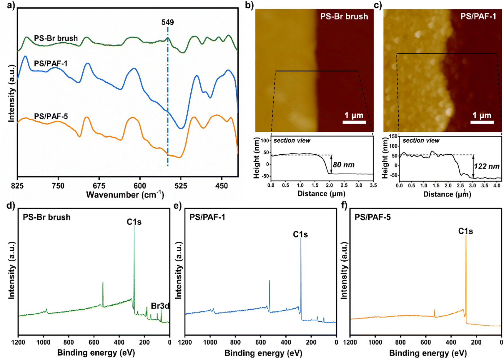 | ||
| Fig. 1 (a) FT-IR spectra for PS-Br brushes, PS/PAF-1 and PS/PAF-5; (b and c) AFM scans and the corresponding sectional view of PS-Br brushes before and after the PAF-1 growth; XPS spectra of PS-Br brushes (d), PS/PAF-1 (e), and PS/PAF-5 (f) on a silicon substrate. | ||
Due to its extremely high specific surface area and high stability, PAF-1 has received a lot of attention from the academic community since its first report in 2009.5 Since an Ullmann coupling reaction was used in the PAF synthesis, the obtained PAF-1 are normally large spheres (∼1 μm) with less controllability. Thus, we selected PAF-1 as the target to investigate its growth behaviour in polymer brushes. Initially, the PS-Br-modified silicon substrate was submerged in a solution containing tetrakis(4-bromophenyl)methane (TBMP) and bis(1,5-cyclooctadiene)nickel(0) ([Ni(cod)2]) and heated at 80 °C. To avoid sedimentation-caused PAF formation on the surface, the substrates were kept with the polymer-modified side facing the bottom of the reaction flask during the reaction. After the coupling reaction was complete, the modified substrates were removed from solution and sonicated in organic solvents with different polarities to ensure that only chemically bonded PAFs remain on the PS-Br brush modified surface. To confirm the formation of PAF-1 on the PS-Br brushes, FT-IR and XPS measurements were performed on the modified substrates. The disappearance of C–Br bonds at 549 cm−1 was observed in the FT-IR spectrum (Fig. 1a), indicating that the Ullmann coupling reaction had proceeded to completion. As shown in Fig. 1e, Br 3d at 70.4 eV had disappeared, which further confirmed the occurrence of the phenyl–phenyl coupling reaction. After the Ullmann coupling reaction, the smooth polymer coating became rough. It is apparent, as observed from atomic force microscopy (AFM) scans, that the surface roughness of the PS-Br brushes (Ra 3.9 nm) was increased by the PAF-1 grafted surface to a higher value of 22.7 nm (Ra) (Fig. 1b and c). Meanwhile, the layer thickness increased from 80 nm for PS-Br brushes to 122 nm for PS/PAF-1 coatings, indicating the formation of PAF-1 in polymer brushes. We attribute the significant increase in thickness to the formation of PAF-1 particles in the interior of the polymer brushes, which force the grafted PS-Br chains to adopt a more stretched conformation.
AFM measurements were conducted to further monitor the evolution of PAF-1 formed on the PS-Br brushes. As shown in Fig. 2a, the diameter of PAF-1 formed in PS-Br brushes gradually increased from 30 to 110 nm as the coupling reaction time was varied from 10 min to 48 h. The diameter increases slightly with the duration of the coupling reaction up to 24 h, but a further increase is not significant when the reaction time is more than 24 h. The PS/PAF-1 coatings were then further analysed by scanning electron microscopy (SEM). The SEM image showed that the coatings formed on the silicon wafer remained continuous and free of defects after PAF-1 formation (Fig. S1†).
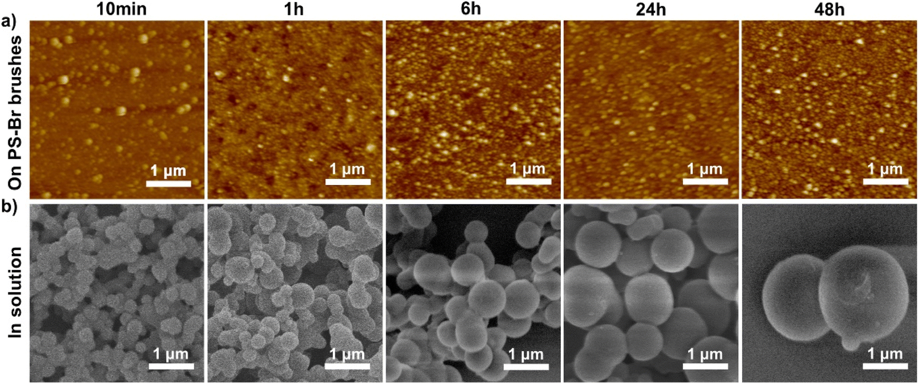 | ||
| Fig. 2 (a) AFM scans of PAF-1 formed in PS-Br brushes at different coupling reaction times; (b) SEM images of PAF-1 formed simultaneously in solution at different times. | ||
The Ullmann coupling reaction occurred both amongst the PS-Br brushes and in solution. PAF-1 powders formed simultaneously in solution were isolated and examined by SEM. As shown in Fig. 2b, PAF-1 powder formed in solution exhibits an amorphous spherical morphology, and the particle size increased from 330 nm to 2 μm when the coupling reaction time increased from 10 min to 48 h. FT-IR, solid-state 13C CP/MAS NMR spectroscopy, and porosity characterisation of the powder obtained in solution are consistent with previous reports, demonstrating that PAF-1 was successfully prepared in solution (Fig. S2†).5 The diameter of PAF-1 in the polymer brushes is considerably smaller than that formed concurrently in solution. The PS-Br brushes were prepared by the method of “grafting from” polymer chains which were densely packed, which offered a particularly effective confined environment for the growth of PAF-1. Furthermore, semi-fixed polymer chains would adopt a swollen conformation in the reaction solution (DMF), which would facilitate the formation of spherical PAF-1 amongst the polymer brushes. Therefore, polymer brushes represent an effective platform for acquiring small-sized PAFs.
In order to explore the influence of other structural parameters of polymer brushes on the growth behaviour of PAF-1 even further, we prepared polymer brushes with lower Br density and lower grafting density to achieve a more delicate modulation of the dimensions of PAF-1. We added styrene to the photografting polymerisation system and copolymerised with 4-bromostyrene to obtain copolymer brushes with different Br densities. Copolymer brushes with a sparse distribution of Br functionality were consequently acquired to induce the growth of PAF-1. The successful formation of copolymer brushes was substantiated by FT-IR spectroscopy, as shown in Fig. S3†. The AFM scan (Fig. 3a–e) shows that the diameter of PAF-1 nanospheres formed on copolymer brushes progressively increased from 90 nm to 500 nm with the increase in styrene feed, indicating that we have realized fine-tuning of the size for PAF-1. With a decrease in the Br density of copolymer brushes, the crosslinking level of PS-Br chains decreases accordingly. As a result, the available free volume in the brush layer increases during the growth of PAF-1. Moreover, polymer brushes still serve as an efficient platform for the synthesis of dimensionally homogeneous PAF-1.
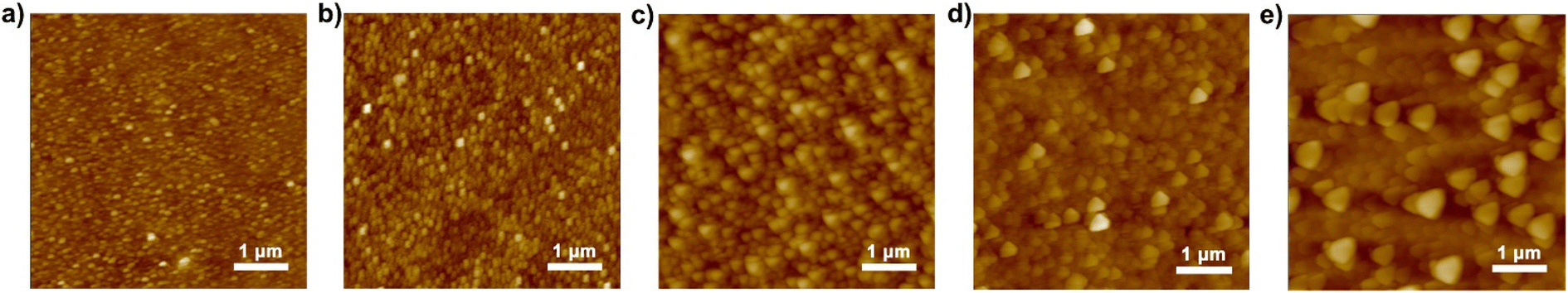 | ||
Fig. 3 AFM scans of PAF-1 growth in polymer brushes with different bromine densities. Feeding ratio of 4-bromostyrene![[thin space (1/6-em)]](https://www.rsc.org/images/entities/char_2009.gif) :styrene, (a) 1:0; (b) 10:1; (c) 3:1; (d) 1:1; (e) 1:10. :styrene, (a) 1:0; (b) 10:1; (c) 3:1; (d) 1:1; (e) 1:10. | ||
In addition, mixed SAMs of APTMS and trimethoxy(propyl)silane (TMPS) (APTMS:TMPS = 1:1000) were prepared for the photografting polymerisation of 4-bromostyrene on a silicon wafer. Since effective sites for grafting polymer chains are amino rather than alkyl functionalities, the grafting polymerisation process occurs selectively at the end of amino groups to obtain PS-Br brushes with lower grafting density. Polymer brushes obtained on mixed SAMs under identical reaction conditions have a thickness of only 20 nm compared to 80 nm on a SAM of APTMS (Fig. 4a), indicating that a low grafting density of PS-Br brushes had been obtained successfully. The PAF-1 nanospheres grown on the prepared polymer brushes with low grafting density are sparsely distributed, as shown in Fig. 4b, and the size of the PAF-1 nanospheres was similar to those formed in solution at the same time. This is because PS-Br brushes with low grafting density adopted a looser conformation in DMF, thus providing more available space for PAF-1 growth.
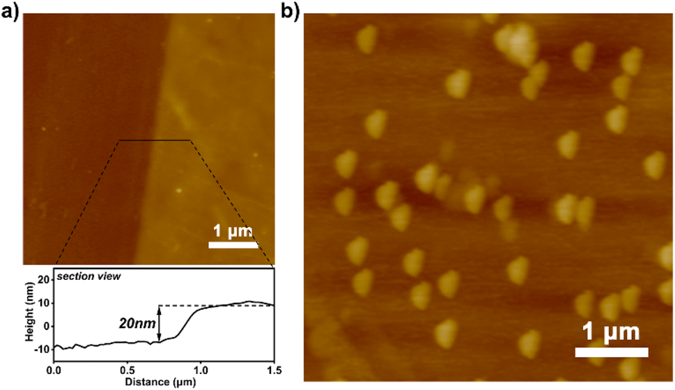 | ||
| Fig. 4 (a) AFM scan of polymer brushes with low grafting densities grown on mixed SAMs and the corresponding sectional view; (b) AFM scan of PAF-1 grown on the brushes. | ||
To verify the confining effect of polymer brushes on the growth of different PAFs, the induced growth of PAF-5 on the surface of PS-Br brushes was attempted.26 According to the synthetic procedure reported previously, we prepared surface-attached PAF-5 by the coupling reaction of 1,3,5-tris-(4-bromophenyl)benzene (TBB) catalysed by Ni(cod)2. The chemical structure of PAF-5 and the corresponding synthetic route are shown in Fig. 5a. Similarly, homogeneous PAF-5 nanospheres with an average diameter of 250 nm were formed in PS-Br brushes, while the diameters of PAF-5 formed simultaneously in solution ranged from 350 to 700 nm (Fig. 5b and c). The formation of PAF-5 in PS-Br brushes was confirmed by FT-IR and XPS measurements. As shown in Fig. 1a, the characteristic peak below 600 cm−1 for C–Br bonds disappears, which proves that the reaction proceeded completely between the brushes and TBB monomer. As shown in Fig. 1f, the disappearance of peaks at 70.4 eV for Br 3d confirms that PAF-5 was successfully formed in the polymer brushes. The formation of PAF-5 in solution was also examined by FT-IR. The disappearance of the peak at 1078 cm−1 of C–Br bonds indicates that PAF-5 was formed (Fig. S4†). These results indicate that PS-Br brushes show an analogous confining effect for PAFs with different structures, demonstrating the universality of the established strategy.
 | ||
| Fig. 5 (a) The chemical structure of PAF-5 and the corresponding synthetic routine; (b) AFM scan of PS/PAF-5; (c) SEM image of PAF-5 formed simultaneously in solution. | ||
The PS-Br brushes were created on a silicon substrate with an oxidized layer, which provides the possibility for the formation of a free-standing polymer membrane after the removal of the silicon oxide layer. According to our previous report,22 the as-synthesized PS/PAF-1-coated silicon substrate was treated in a hydrofluoric acid aqueous solution to remove the silicon oxide layer. As a result, we obtained a free-standing PS/PAF-1 hybrid membrane with good mechanical stability and integrity. The thicknesses of the membrane are almost identical before and after membrane transfer, as shown in the AFM scans (Fig. S5†). This also indicates that HF etches only oxides, i.e. the polymer membranes are not chemically sacrificed during the etching process. The optical image and SEM image (Fig. 6a and b) show that the prepared PS/PAF-1 hybrid membrane is defect-free, flexible, and can be obtained with a dimension up to 1 cm. The high resolution transmission electron microscopy (HRTEM) image (Fig. S6b†) shows that the worm-like texture in the PAF region of the PS/PAF-1 hybrid membrane has a clear porous character.27 In comparison to the less rough PS region (Fig. S6a†), the PAF region has more dense pores and the pores are interconnected.
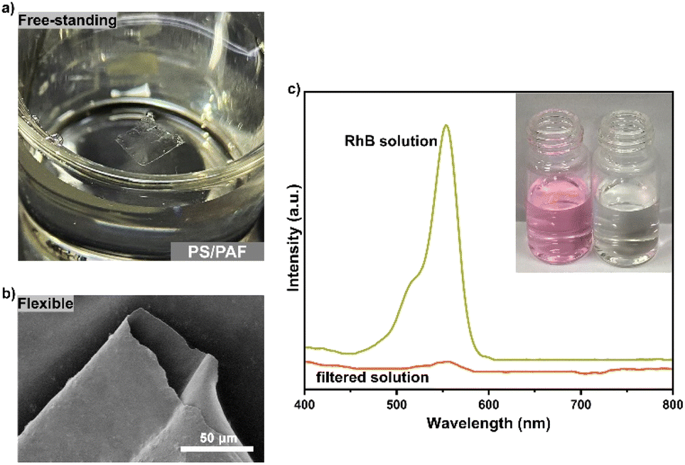 | ||
| Fig. 6 (a) Optical image of the free-standing PS/PAF-1 hybrid membrane after lifted off from the substrate; (b) SEM image of free-standing PS/PAF-1 hybrid membrane after transferred to silicon wafer; (c) UV-vis spectra of RhB aqueous solutions before and after the filtration through the PS/PAF-1 hybrid membrane (inset: optical pictures for RhB aqueous solutions before and after the filtration). | ||
Due to the structural stability and porous character of PS/PAFs, it is expected that the hybrid membrane will be effective in the purification of dye-contaminated water.28 Rhodamine B (RhB), a typical dye molecule, was selected as the contaminant model for successive membrane separation investigation. The continuous flow device is shown in Fig. S7†. RhB aqueous solution (10 ppm) was forced by a peristaltic pump at a flow rate of 2 mL min−1 through the PS/PAF-1 hybrid membrane (1 × 1 cm2), and the filtered solution was collected and tested by UV-vis spectroscopy (Fig. 6c). By comparing the change in absorbance before and after filtration, the removal efficiency of the PS/PAF-1 hybrid membrane was calculated to be 99.9%. The performance stability of the PS/PAF-1 hybrid membrane was investigated by dynamic adsorption experiments. Ct/C0 = 0.02 was defined as a breakthrough point (98% removal). Up to the breakthrough point, the PS/PAF-1 hybrid membrane could continuously produce 290 mL of clear water (Fig. S8†). The membrane separation ability to remove the dye molecules is due to the high porosity of PS/PAF-1, indicating that the PS/PAF-1 hybrid membrane has high retention capacity for dye molecules.
Experimental
Materials and methods
All chemicals were purchased from Aladdin, Energy Chemical Co. Ltd, Beijing Chemical Reagent Company, and Jilin Chinese Academy of Science-Yanshen Technology Co. Ltd, and used without further purification if not otherwise noted. 4-Bromostyrene, styrene, 3-aminopropyltrimethoxysilane (APTMS) and trimethoxy(propyl)silane (TMPS), were purified by heating over CaH2 and subsequent distillation under vacuum before use. SiO2 substrates were purchased from Beijing Ying Zuo Nano Science and Technology Company (China), and were rinsed thoroughly with deionized water, ethanol, and ethyl acetate, and dried in a stream of nitrogen prior to use. A photochemical reactor (PL-DY1600) with a spectral distribution from 300 nm to 400 nm, was purchased from Beijing Princess Technology Co. Ltd.Atomic force microscopy (AFM) was performed using an Oxford Instruments Cypher ES. The modulus measurements were performed in an atomic force microscope system (Brucker, Berlin, Germany). FT-IR spectra were recorded on a Thermo Scientific Nicolet iS20 FT-IR spectrophotometer equipped with an iD5 diamond ATR attachment. X-ray photoelectron spectroscopy (XPS) was performed using a Shimadzu/Krayos AXIS Ultra DLD (Japan), with Al-Kα as the achromatic X-ray source. Surface spectra were collected over a range of 0–1200 eV. Solid-state 13C CP/MAS NMR spectra were obtained using a Bruker Avance III model 500 MHz NMR spectrometer at a MAS rate of 5 kHz. The N2 adsorption–desorption isotherm was determined at 77 K using Quantachrome Autosorb iQ apparatus. The scanning electron microscope (SEM) images were acquired using a JEOL JSM 4800F SEM. High resolution transmission electron microscopy (HRTEM) was recorded using a JEOL JEM-F200 with an acceleration voltage of 200 kV. The UV-vis spectra were collected by an ultraviolet spectrophotometer (Shimadzu).
Preparation of self-assembled monolayers (SAMs)
Aminated silicon wafer substrates were prepared as previously reported.23 Initially, a silicon wafer substrate was cleaned thoroughly with deionized water, ethanol, and ethyl acetate by ultrasonic cleaning, and then dried in a stream of nitrogen before use. Then it was submerged in a Piranha solution (H2O2/H2SO4 = 1/2, caution!) for 24 h at 100 °C. The substrates which were rich in surface hydroxyl groups were heated in a flask with 10 wt% APTMS or a mixture of APTMS and TMPS acetone solution for 48 h at 40 °C under an argon atmosphere for the preparation of SAMs. Ultimately, the SAM-modified silicon wafer substrate was rinsed with deionized water, ethanol, and later ethyl acetate, and then dried for further use.Preparation of PS-Br brushes and poly(4-bromostyrene-co-styrene) brushes
The SAM-modified substrates were submerged in degassed bulk 4-bromostyrene or a mixture of styrene and 4-bromostyrene, which were mixed in proportion for UV irradiation in a photoreaction tube. The reactions were allowed to proceed for a maximum of 5 h to avoid bulk gelation. The substrates were then thoroughly cleaned in toluene, ethanol and later ethyl acetate under constant ultrasonication to remove unreacted monomer and only physically adsorbed polymers on the surface. Ultimately, the polymer brushes were flow-dried with pure nitrogen.Synthesis of PAF-1 in PS-Br brushes (PS/PAF-1)
The synthesis of PAF-1 in PS-Br brushes and in solution was carried out as follows. 1,5-Cyclooctadiene (cod, 0.1 mL, 0.792 mmol, dried over CaH2) was added to a solution of bis(1,5-cyclooctadiene)nickel(0) ([Ni(cod)2], 225 mg, 0.818 mmol) and 2,2′-bipyridyl (128 mg, 0.818 mmol) in dehydrated DMF (12 mL). Meanwhile, PS-Br-modified substrate was added into the flask, and then the reaction system was activated for 1 h at 80 °C. TBMP (100 mg, 0.157 mmol) was added to the resulting purple solution, and the mixture was stirred at 80 °C overnight. After the reaction, HCl was added to the mixture when the reaction system had cooled to room temperature. The silicon wafer substrate was separated from the powder and subjected to separate post-treatment. The PAF-1-anchored substrate was thoroughly rinsed and sonicated repeatedly with methanol and THF. The powder was post-treated as previously reported 5.Synthesis of PAF-5 in PS-Br brushes (PS/PAF-5)
Briefly, 1,5-cyclooctadiene (cod, 0.47 mL, 0.396 mmol, dried over CaH2) was added to a solution of bis(1,5-cyclooctadiene)nickel(0) ([Ni(cod)2], 109 mg, 0.397 mmol) and 2,2′-bipyridyl (62 mg, 0.397 mmol) in dehydrated DMF (4 mL). Meanwhile, PS-Br-modified substrate was added to the flask, and then the reaction system was activated for 1 h at 80 °C. TBB (59.5 mg, 0.11 mmol) was added to the resulting purple solution, and the mixture was stirred at 80 °C for 1 day. After cooling to room temperature, concentrated HCl was added to the mixture. The PAF-5 powder was post-treated as previously reported.26 The PAF-5-anchored substrate was thoroughly rinsed and sonicated repeatedly with methanol and THF, and dried prior to characterisation.Fabrication of free-standing PS/PAF hybrid membranes
According to the previously reported membrane transfer process of CMP, a thin layer of poly(methylmethacrylate) (PMMA) was first spin-coated onto the silicon wafer for thin layer protection.21 The silicon wafer was then placed in 2% HF solution to etch the SiO2 layer. Finally, the PMMA protecting layer on the surface was removed by washing with acetone.Conclusions
In summary, we have established a novel paradigm for the preparation of surface-attached PAFs in polymer brushes bearing bromine functionalities. The semi-fixed polymer chains provide a confined environment for the growth of PAFs to form ultra-small PAF nanospheres. By simply modulating the structural parameters of the polymer brushes, the size of PAFs on the surface can be tailored. The established method not only works for the synthesis of PAF-1 and PAF-5, but is also promising for the controlled synthesis of other surface-attached POFs. Moreover, we have also obtained a free-standing PS/PAF hybrid membrane, which has high mechanical and chemical stability, and good flexibility. We further showed the potential of the membrane for separation, e.g. dyes can be efficiently removed from contaminated water. This strategy may provide a feasible idea for the preparation of other porous organic membranes, which will be promising for applications in liquid separation, gas separation and so on.Data availability
SEM, AFM, HRTEM, FT-IR, solid-state 13C CP/MAS NMR, nitrogen adsorption–desorption isotherm and the adsorption curve of the samples, and the optical image of continuous flow device have been included in the ESI.†Author contributions
N. Z. and G. Z. conceived and directed this work. R. Y. conducted the synthesis and characterisation of PS/PAFs. L. L. prepared PS/PAF hybrid membranes. L. Y., Y. J. and H. B. analysed the experimental data.Conflicts of interest
There are no conflicts to declare.Acknowledgements
We are grateful for financial support from the National Natural Science Foundation of China (Grant No. 51973026, 51903101) and the Department of Science and Technology of Jilin Province (Grant No. YDZJ202201ZYTS592, 20220101230JC).Notes and references
- A. P. Côté, A. I. Benin, N. W. Ockwig, M. O’keeffe, A. J. Matzger and O. M. Yaghi, Science, 2005, 310, 1166–1170 CrossRef PubMed.
- C. D. Wood, B. Tan, A. Triewin, H. Niu, D. Bradshaw, M. J. Rosseinsky, Y. Z. Khimyak, N. L. Campbell, R. Kirk, E. Stöckel and A. I. Cooper, Chem. Mater., 2007, 19, 2034–2048 CrossRef CAS.
- J. Jiang, F. Su, A. Trewin, C. D. Wood, N. L. Campbell, H. Niu, C. Dickinson, A. Y. Ganin, M. J. Rosseinsky, Y. Z. Khimyak and A. I. Cooper, Angew. Chem., 2007, 119, 8728–8732 CrossRef.
- P. Kuhn, M. Antonietti and A. Thomas, Angew. Chem., Int. Ed., 2008, 47, 3450–3453 CrossRef CAS PubMed.
- T. Ben, H. Ren, S. Ma, D. Cao, J. Lan, X. Jing, W. Wang, J. Xu, F. Deng, J. M. Simmons, S. Qiu and G. Zhu, Angew. Chem., Int. Ed., 2009, 48, 9457–9460 CrossRef CAS PubMed.
- M. A. Little and A. I. Cooper, Adv. Funct. Mater., 2020, 30, 1909842 CrossRef CAS.
- Y. Tian and G. Zhu, Chem. Rev., 2020, 120, 8934–8986 CrossRef CAS PubMed.
- M. Sun, S. Huang, L. Chen, Y. Li, X. Yang, Z. Yuan and B. Su, Chem. Soc. Rev., 2016, 45, 3479–3563 RSC.
- S. Das, P. Heasman, T. Ben and S. Qiu, Chem. Rev., 2017, 117, 1515–1563 CrossRef CAS PubMed.
- L. Yin, Z. Wang, Q. Wu, L. Liu, N. Zhang, Z. Xie and G. Zhu, ACS Nano, 2022, 16, 6197–6205 CrossRef CAS PubMed.
- N. Singh, S. Son, J. An, I. Kim, M. Choi, N. Kong, W. Tao and J. S. Kim, Chem. Soc. Rev., 2021, 50, 12883–12896 RSC.
- A. Comotti, S. Bracco, M. Mauri, S. Mottadelli, T. Ben, S. Qiu and P. Sozzani, Angew. Chem., Int. Ed., 2012, 51, 10136–10140 CrossRef CAS PubMed.
- L. Hou, M. Zhou, X. Dong, L. Wang, Z. Xie, D. Dong and N. Zhang, Chem. – Eur. J., 2017, 23, 13337–13341 CrossRef CAS PubMed.
- P. Pachfule, B. K. Balan, S. Kurungot and R. Banerjee, Chem. Commun., 2012, 48, 2009–2011 RSC.
- S. Zhou, X. Kong, B. Zheng, F. Huo, M. Strømme and C. Xu, ACS Nano, 2019, 13, 9578–9586 CrossRef CAS PubMed.
- T. Hasell and A. I. Cooper, Nat. Rev. Mater., 2016, 1, 16053 CrossRef CAS.
- S. T. Milner, Science, 1991, 251, 905–914 CrossRef CAS PubMed.
- R. Barbey, L. Lavanant, D. Paripovic, N. Schüwer, C. Sugnaux, S. Tugulu and H. A. Klok, Chem. Rev., 2009, 109, 5437–5527 CrossRef CAS PubMed.
- S. V. Orski, K. H. Fries, S. K. Sontag and J. Locklin, J. Mater. Chem., 2011, 21, 14135–14149 RSC.
- L. Yin, L. Liu and N. Zhang, Chem. Commun., 2021, 57, 10484–10499 RSC.
- B. Liang, H. Wang, X. Shi, B. Shen, X. He, Z. A. Ghazi, N. A. Khan, H. Sin, A. M. Khattak, L. Li and Z. Tang, Nat. Chem., 2018, 10, 961–967 CrossRef CAS PubMed.
- L. Liu, L. Yin, D. Cheng, S. Zhao, H. Zang, N. Zhang and G. Zhu, Angew. Chem., Int. Ed., 2021, 60, 14875–14880 CrossRef CAS PubMed.
- N. Zhang, T. Pompe, I. Amin, R. Luxenhofer, C. Werner and R. Jordan, Macromol. Biosci., 2012, 12, 926–936 CrossRef CAS PubMed.
- J. Deng, W. Yang and B. Rånby, Macromol. Rapid Commun., 2001, 22, 535–538 CrossRef CAS.
- T. B. Stachowiak, F. Svec and J. M. J. Fréchet, Chem. Mater., 2006, 18, 5950–5957 CrossRef CAS.
- H. Ren, T. Ben, F. Sun, M. Guo, X. Jing, H. Ma, K. Cai, S. Qiu and G. Zhu, J. Mater. Chem., 2011, 21, 10348–10353 RSC.
- Z. Huang, F. Kang, W. Huang, J. Yang, K. Liang, M. Cui and Z. Cheng, J. Colloid Interface Sci., 2002, 249, 453–457 CrossRef CAS PubMed.
- Y. Song, J. Phipps, C. Zhu and S. Ma, Angew. Chem., Int. Ed., 2023, e202216724 CAS.
Footnotes |
| † Electronic supplementary information (ESI) available. See DOI: https://doi.org/10.1039/d2sc06930j |
| ‡ These authors are contributed equally to this work. |
| This journal is © The Royal Society of Chemistry 2023 |