
 Open Access Article
 This Open Access Article is licensed under a Creative Commons Attribution-Non Commercial 3.0 Unported Licence
Detection and differentiation of per- and polyfluoroalkyl substances (PFAS) in water using a fluorescent imprint-and-report sensor array†
Emily E.
Harrison
and
Marcey L.
Waters
 *
*
Department of Chemistry, University of North Carolina at Chapel Hill, Chapel Hill, North Carolina 27599, USA. E-mail: mlwaters@email.unc.edu
First published on 29th December 2022
Abstract
Widespread industrial use of per- and polyfluoroalkyl substances (PFAS) as surfactants has led to global contamination of water sources with these persistent, highly stable chemicals. As a result, humans and wildlife are regularly exposed to PFAS, which have been shown to bioaccumulate and cause adverse health effects. Methods for detecting PFAS in water are currently limited and primarily utilize mass spectrometry (MS), which is time-consuming and requires expensive instrumentation. Thus, new methods are needed to rapidly and reliably assess the pollution level of water sources. While some fluorescent PFAS sensors exist, they typically function in high nanomolar or micromolar concentration ranges and focus on sensing only 1–2 individual PFAS. Our work aims to address this problem by developing a fluorescent sensor for both individual PFAS, as well as complex PFAS mixtures, and demonstrate its functionality in tap water samples. Here we show that dynamic combinatorial libraries (DCLs) with simple building blocks can be templated with a fluorophore and subsequently used as sensors to form an array that differentially detects each PFAS species and various mixtures thereof. Our method is a high-throughput analysis technique that allows many samples to be analyzed simultaneously with a plate reader. This is one of the first examples of a fluorescent PFAS sensor array that functions at low nanomolar concentrations, and herein we report its use for the rapid detection of PFAS contamination in water.
Introduction
Per- and polyfluoroalkyl substances (PFAS) have been recognized as a significant threat to our environment and health as they continue to accumulate in global water sources due to extensive use in industrial production.1–7 Owing to their high stability and both hydro- and oleophobic properties, PFAS have found use in commercial products including cosmetics,8 food packaging,9 cookware,10 stain-resistant furniture coatings,10 and fire-fighting foam,11 among others.12,13In the past couple of decades many studies have shed light on the toxicity of PFAS,14–21 prompting the Environmental Protection Agency (EPA) to impose drinking water limits for several of the most prominent contaminants, namely perfluorooctanesulfonic acid (PFOS) and perfluorooctanoic acid (PFOA). PFOA has been identified as a possible carcinogen leading to higher incidences of testicular and kidney cancers,17 while PFAS generally have been linked to many other health concerns, including higher cholesterol,14 hepatotoxicity,14 thyroid disease,18 immunotoxicity,19,20 and reduced fertility.21 While newer short-chain PFAS have been developed with the goal of decreasing toxicity, such as perfluoro-2-propoxypropanoic acid (GenX),22 they are being linked to many of the same health concerns as legacy PFAS but may possess shorter half-lives.23,24
Sensitive detection methods for these “forever chemicals” are critical for evaluating the safety of our water sources. Many existing methods utilize mass spectrometry (MS),22,25–30 but despite the accuracy and sensitivity of MS, its limitations include the need for expensive instrumentation, time-consuming sequential sample analysis, and often isotope-labeled analytical standards. Alternative detection methods that are more cost-effective and high-throughput, such as fluorescent sensors that can be rapidly analyzed in well plate format, are highly desirable.
One of the largest current challenges among fluorescent detection methods is achieving a measurable output within a relevant PFAS concentration range. While environmental PFAS contamination is typically in the femtomolar to picomolar range,3,4 most fluorescent sensors operate in the high nanomolar or micromolar range.31–35 Among the most successful examples thus far are the use of aggregation-induced emission luminogens assembled on a chip that can detect PFOA and PFOS as low as 100 nM reported by Fang et al.,36 and an indicator displacement assay (IDA) using a guanidinocalix[5]arene and fluorescein to detect PFOA and PFOS with limits of detection (LODs) of 26.4 nM and 21.4 nM, respectively, developed by Zheng et al.37 Sensor arrays have previously been developed as a facile method of detecting and distinguishing several analytes with similar structures from one another using pattern recognition,38–41 but only a couple of sensor arrays for PFAS currently exist.42,43 Typically, developing a sensor array involves identifying and synthesizing a set of hosts that exhibit differential binding profiles towards the analytes and colorimetric or fluorescent reporter(s). When the reporter(s) and analytes are in competition with one another for binding to each host, a unique pattern of outputs is obtained, allowing for visual differentiation via the statistical tool principal component analysis (PCA).44,45 One PFAS sensor array developed by Chen and co-workers utilizes luminescent metal–organic frameworks (MOFs) to distinguish six PFAS at low micromolar concentrations.42 The utility of the array is also demonstrated with a set of PFAS mixtures and in spiked environmental water samples, but the PFAS concentrations detected are several orders of magnitude higher than levels of environmental contamination. Another array developed by Yin et al. is comprised of functionalized nanoparticles and discriminates seven individual PFAS with a reported LOD of 40 nM and various molar ratios of PFOS and PFHxA at a total concentration of 0.6 μM.43 Herein, we describe a novel fluorescent sensor array that differentially detects PFAS, both individual species and complex mixtures in buffer and tap water, at the lowest reported PFAS concentrations (5–40 nM) using dynamic combinatorial chemistry (DCC)46 to generate a set of dynamic combinatorial libraries (DCLs) containing macrocyclic species templated with a fluorophore. We have previously reported this method, called imprint-and-report sensing, as a high-throughput means for differentiating protein post-translational modifications (PTMs),47 as well as a set of dietary metabolites in human plasma samples,48 demonstrating the adaptability and applicability of the system. For the PFAS sensing reported herein, new DCLs containing a fluorinated monomer were optimized to enhance interactions with the fluorinated analytes.
Imprint-and-report sensor arrays use combinations of exchangeable dithiol building blocks to generate a set of DCLs, which are templated with an environmentally sensitive fluorophore. The DCLs are allowed to completely equilibrate and oxidize, such that macrocyclic speciation that is imprinted by the fluorophore template is locked in. Analytes can then be added to aliquots of the imprinted DCL to generate a competitive binding scenario and thus a fluorescence report.47 Unique reported patterns based on the interactions between each analyte with several DCLs create analyte differentiation via PCA (Fig. 1a). The merits of imprint-and-report sensing are that receptors are generated in situ, thereby obviating the need for individual host development and synthesis, and that utilizing a mixture of hosts instead of just one species affords the opportunity for additional host–guest interactions that may lead to enhanced differential signal (Fig. 1b). Moreover, the DCL sensors can readily be adapted for new analytes by modifying the dithiol building blocks that are used.48
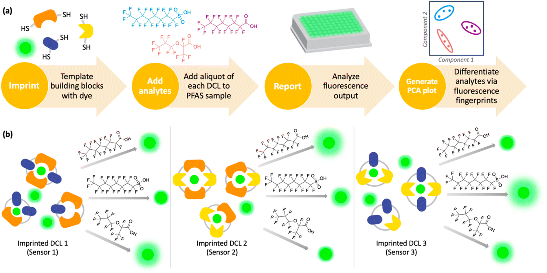 | ||
| Fig. 1 (a) Scheme depicting the workflow of an imprint-and-report sensor array used to sense and differentiate analytes, such as PFAS. DCLs are first imprinted with a fluorophore, followed by analyte addition, fluorescence analysis, and differentiation via PCA. (b) Scheme illustrating the generation of sensor array data using three imprinted DCL sensors and adding PFAS analytes to produce different fluorescent patterns. | ||
Using this imprint-and-report methodology, we developed a PFAS sensor array and observed successful differentiation of six prominent PFAS contaminants: PFOS (perfluorooctanesulfonic acid), PFOA (perfluorooctanoic acid), GenX, perfluoroheptanoic acid (PFHpA), perfluorohexanoic acid (PFHxA), and perfluoropentanoic acid (PFPeA) (Fig. 2). We show that use of a fluorinated building block in the DCL sensors improves sensing capabilities and allows full distinction of these six PFAS at 5 nM, as well as detection and differentiation of various PFAS mixtures at 20 nM. Finally, we demonstrate that tap water samples spiked with PFAS mixtures can be discriminated based on total PFAS concentration at 40 nM, rather than the specific individual components, streamlining sensing of complex mixtures. To our knowledge, this system is the most sensitive fluorescent PFAS sensing technique reported to date and has the widest sensing scope, as it detects several of the most prevalent PFAS as well as complex mixtures. Thus, it represents an important advancement in the detection of environmental contaminants that pose great risks to human health.
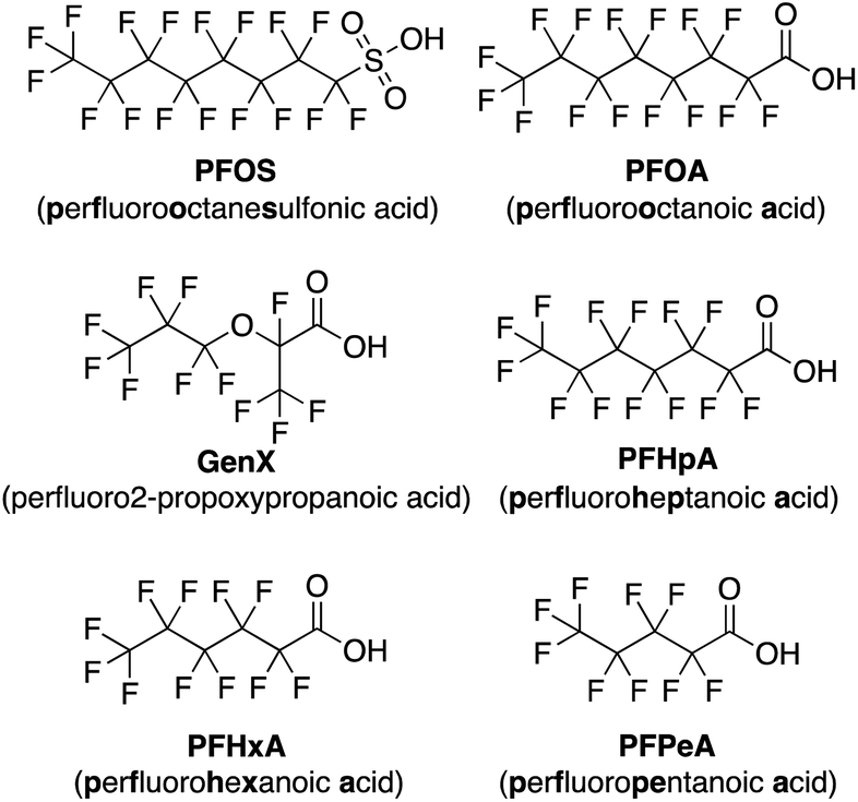 | ||
| Fig. 2 Structures of the PFAS detected by the imprint-and-report array. | ||
Results and discussion
High levels of PFAS are of particular concern in North Carolina, namely in the Cape Fear River Basin, due in part to nearby PFAS manufacturing plants that have released the contaminants into the environment since the 1950s.3 As a result, we narrowed our selection of PFAS for sensor array development to those that are some of the most prevalent contaminants in NC: PFOA, PFOS, GenX, PFHpA, PFHxA, and PFPeA.49 To initially screen for differential fluorescence sensing using the imprint-and-report system, we selected three building blocks (E,50 G,51 and N52) that we have previously used in the detection of PTMs, as well as the fluorophore lucigenin (LCG), which has been used in previous imprint-and-report arrays (Fig. 3).47,48 The four LCG-templated DCLs formed from these building blocks in 50 mM sodium borate buffer at pH 8.5 (E + G, G + N, E + N, and E + G + N) have been characterized47 and thus allowed us to gain a facile understanding of the promise of this system for PFAS detection. Despite the building blocks and PFAS all being negatively charged, we anticipated that the fluorinated tails of the PFAS may bind to receptors in aqueous solution due to the hydrophobicity of both species. Moreover, one of the key advantages of differential sensing is the requirement for differentially binding receptors rather than highly selective receptors.39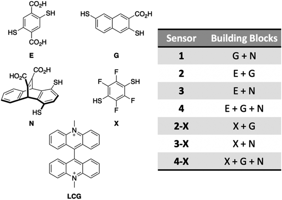 | ||
| Fig. 3 Structures of DCC building blocks E, G, N, and X and the fluorophore template LCG (left), and the composition of each DCL sensor (right). | ||
Using these four DCLs (sensors 1–4; Fig. 3), we first tested for PFAS discrimination at 100 nM DCL (100 nM total building blocks and 100 nM LCG) and 20 nM PFAS. DCLs were first equilibrated at 1.0 mM for five days, which we have previously verified allows for full oxidation and thus imprinted speciation.47 Aliquots of PFAS stock solutions made in 50 mM sodium borate buffer (pH 8.5) were then added to each DCL, such that final assay samples were all in 50 mM borate buffer. After adding PFAS analytes to the DCLs, the assay samples were placed on a shaker plate for one hour prior to analysis on a plate reader. A No Guest sample of borate buffer (pH 8.5) with no added PFAS was included as a negative control.
Fluorescence data from a minimum of three DCLs is needed to generate a 2-dimensional PCA plot, so each assay analyzed using four DCLs can generate a total of five PCA plots: data from DCLs 1 + 2 + 3 + 4, 1 + 2 + 3, 1 + 2 + 4, 1 + 3 + 4, and 2 + 3 + 4. For each assay described herein, all of these PCA combinations were analyzed and the plot displaying the highest degree of ellipse separation (i.e. the fewest overlapping ellipses) was selected. All PCA plots for each assay are shown in the ESI.† For the 20 nM PFAS assay, the best separation was observed using sensors 1, 2, and 3 (G + N, E + G, and E + N DCLs); however, this plot still shows overlap among the ellipses for GenX, PFOS, and PFHxA (Fig. 4a). It is important to note that the No Guest ellipse is fully separated, so while these array conditions cannot confidently distinguish all six PFAS, they can distinguish a sample containing any of the PFAS from one that does not.
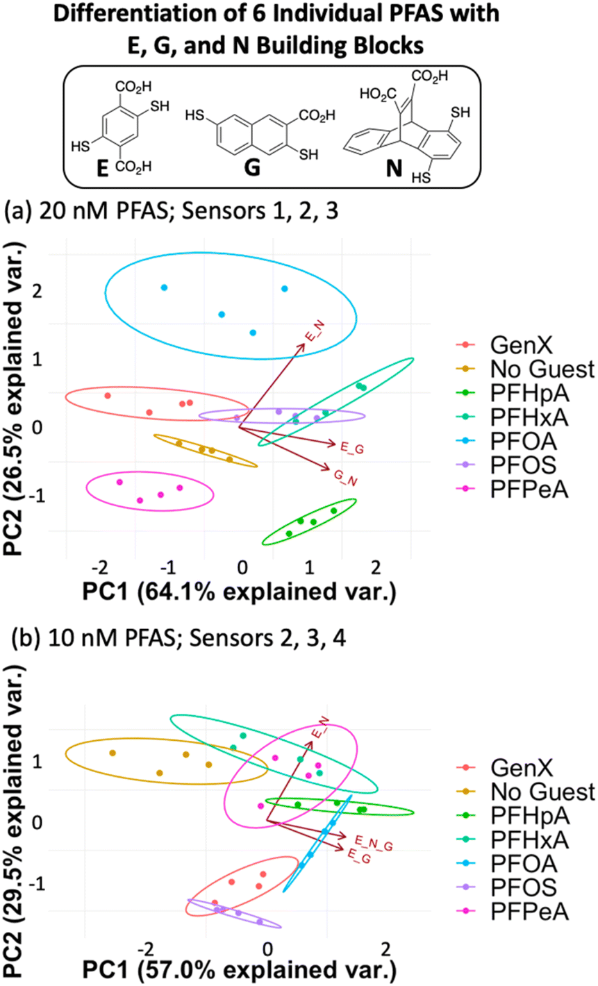 | ||
| Fig. 4 PCA plots displaying detection of six individual PFAS and a No Guest sample in 50 mM sodium borate buffer (pH 8.5) using (a) sensors 1, 2, and 3 (G + N, E + G, and E + N DCLs) at 20 nM PFAS and (b) sensors 2, 3, and 4 (E + G, E + N, and E + G + N DCLs) at 10 nM PFAS. | ||
The data point scatter within an ellipse provides insight into contributions of the sensors to differentiation. Point scatter along a particular vector represents error within the four sample replicates in each cluster for that sensor. For example, in Fig. 4a, the data points for PFHpA and PFHxA exhibit scatter along the vector for the E + N sensor (sensor 3), whereas GenX, PFOA, PFOS, and PFHeA all exhibit scatter along the vectors for the G + N and/or E + G sensors (sensors 1 and 2). This scatter contributes to the lack of differentiation of all PFAS, but the means of many of the data clusters are still separated along both PC1 and PC2. The vectors indicate that the G + N and E + G libraries (sensors 1 and 2) contribute primarily to PC1 and differentiate PFHpA and PFHxA from the shorter-chain GenX and PFPeA. The E + N DCL (sensor 3) contributes primarily to PC2 based on its orientation in the plot and differentiates PFOA from GenX, PFHxA, and PFOS, which are clustered in the middle along PC2, and PFHpA and PFPeA near the bottom of PC2.
Upon lowering the PFAS concentration to 10 nM (Fig. 4b) and 5 nM (Fig. S8†) with the same DCLs at 100 nM, the resulting arrays show no separation, indicating that this set of DCLs is not sensitive enough to achieve differential fluorescence sensing below 20 nM. Nonetheless, the level of separation achieved at 20 nM suggests that the PFAS indeed interact differentially with species in the DCLs, which is surprising given their highly similar structures but promising for array optimization.
We hypothesized that the DCL sensors might be further improved by incorporating a fluorinated building block due to the well-established partitioning of fluoroalkanes, alkanes, and water, known as the fluorous effect.53–56 Thus, replacing building block E with the analogous fluorinated building block X (Fig. 3), which has been reported previously,57 in DCLs within the imprint-and-report array (sensors 2-X, 3-X, and 4-X) may leverage the fluorous effect by introducing fluorine–fluorine host–guest interactions and creating tighter binding. Moreover, X has no carboxylates while E has two in pH 8.5 borate buffer, which may present another advantage of X over E, since removing the negative charges of E will create less repulsion between hosts containing X and the negatively charged PFAS. Conveniently, X maintains water solubility because the electronegative fluorine atoms lower the pKas of the thiols.
We found that using the set of four DCLs with building blocks X, G, and N (sensors 1, 2-X, 3-X, and 4-X), the sensor array has improved discrimination capabilities at even lower PFAS concentrations, consistent with our hypothesis. Full separation of all six PFAS, as well as No Guest, is achieved at 5 nM PFAS with 100 nM of sensors 1, 2-X, and 3-X (G + N, X + G, and X + N DCLs) (Fig. 5a). This plot displays much less data point spread than those using the E, G, and N DCLs, with only slight spread observed in the PFOA and GenX samples along the direction of the G + N and/or X + N vectors, which does not interfere with differentiation of samples. This indicates larger error in the fluorescence measurements of those samples with sensors 1 and 3-X, which is consistent with the error in the raw fluorescence measurements.
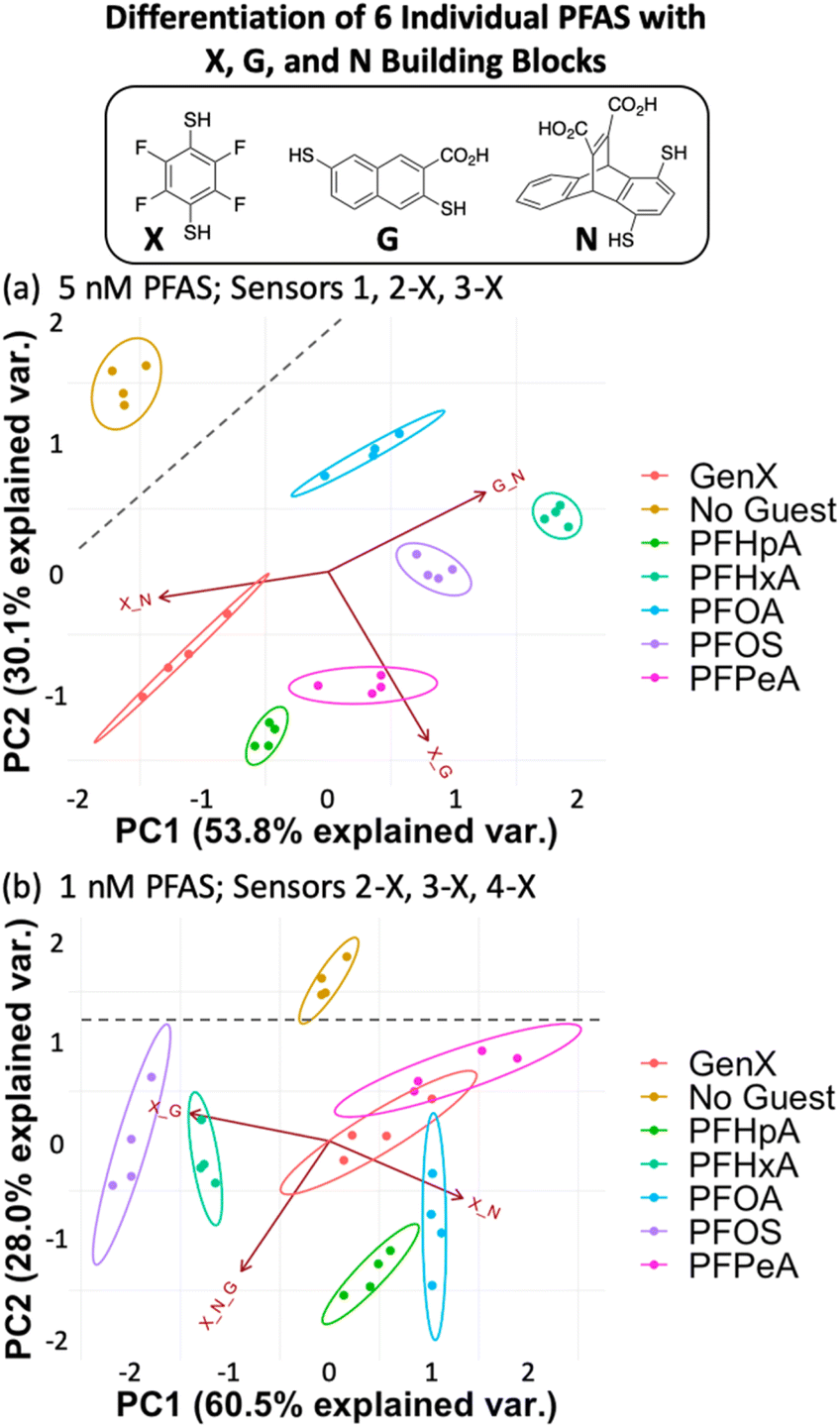 | ||
| Fig. 5 PCA plots displaying detection of six individual PFAS and a No Guest sample in 50 mM sodium borate buffer (pH 8.5) using (a) sensors 1, 2-X, and 3-X (X + G, G + N, and X + N DCLs) at 5 nM PFAS and (b) sensors 2-X, 3-X, and 4-X (X + G, X + N, and X + G + N DCLs) at 1 nM PFAS. Both plots are shown with 95% confidence ellipses. Gray dashed lines denote separation between the No Guest sample and PFAS. | ||
At 1 nM PFAS, we observe slight overlap between GenX, PFPeA, and PFOA, but separation from the No Guest sample is maintained, meaning a sample containing no PFAS can be differentiated from one containing any of the PFAS at this concentration. To assess the limits of the system, we also tested the array at 0.5 nM PFAS and saw no separation (Fig. S11†).
To better understand the sensing system, we analyzed the normalized fluorescence bar graphs for each of the DCLs used to create full separation in the 5 nM PFAS array (Fig. 6). The X + G DCL (sensor 2-X) shows only fluorescence enhancement upon addition of all PFAS relative to the No Guest sample, suggesting LCG is displaced from receptors upon PFAS binding to create turn-on fluorescence, as expected. However, with the G + N DCL (sensor 1), some PFAS result in a fluorescence increase, while others result in quenching, and only quenching is observed with the X + N DCL (sensor 3-X). This suggests there is likely a combination of interaction mechanisms at play; while in some DCLs, PFAS appear to outcompete LCG binding to receptors, giving turn-on fluorescence, in some cases the addition of PFAS seems to result in more bound LCG and thus more quenching (Fig. 7). One possible mechanism for this is the formation a ternary complex, perhaps arising from the combination of both an ion pair between the positively charged LCG and negatively charged PFAS, which then together associate with hosts and lead to a turn-off fluorescence signal.
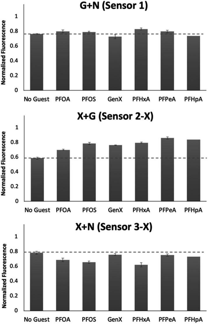 | ||
| Fig. 6 Bar graphs depicting the normalized fluorescence of the G + N (sensor 1), X + G (sensor 2-X), and X + N (sensor 3-X) DCLs upon addition of 5 nM of each PFAS. Error bars represent the standard deviation of four replicate samples. | ||
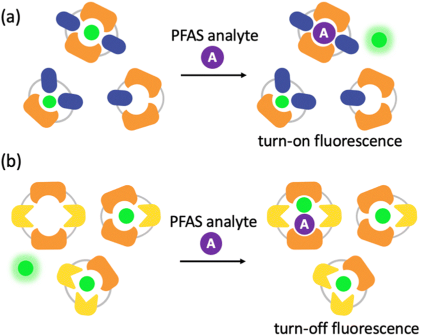 | ||
| Fig. 7 Cartoon schemes representing two possible interaction mechanisms: (a) turn-on fluorescence caused by PFAS binding to a receptor and displacing fluorophore and (b) turn-off fluorescence caused by the formation of a ternary complex between a receptor, fluorophore, and PFAS. | ||
To gain insight into the mechanism of sensing, we evaluated direct interactions between LCG and the PFAS, as in several reported fluorescent PFAS sensors, the PFAS were shown to directly affect the fluorescence of an indicator species.31,33,37 We found, however, that no fluorescence quenching or enhancement of LCG (100 nM) is observed in the presence of 5 nM PFAS (Fig. 8). This indicates that the unique PFAS detection produced by the imprint-and-report array at 5 nM is a result of interactions between the DCL hosts, LCG, and PFAS, not simply due to differential interactions between LCG and PFAS alone. To evaluate the importance of DCL templation by LCG, we performed the same assay with untemplated X + G, G + N, and X + N DCLs in which the PFAS and LCG were added simultaneously to pre-equilibrated DCLs at the same concentrations as in the templated experiments (100 nM LCG and 5 nM PFAS). We found that no differentiation of PFAS is achieved under these conditions (Fig. 9), confirming that LCG templation is also necessary and suggesting that species formed in the presence of LCG bind to the PFAS.
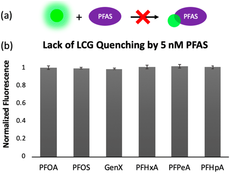 | ||
| Fig. 8 (a) Cartoon representing the lack of fluorescence quenching effect that is observed when 100 nM LCG is exposed to 5 nM PFAS. (b) Normalized fluorescence of samples containing 100 nM LCG and 5 nM PFAS, showing that no fluorescence change is observed without DCLs present. | ||
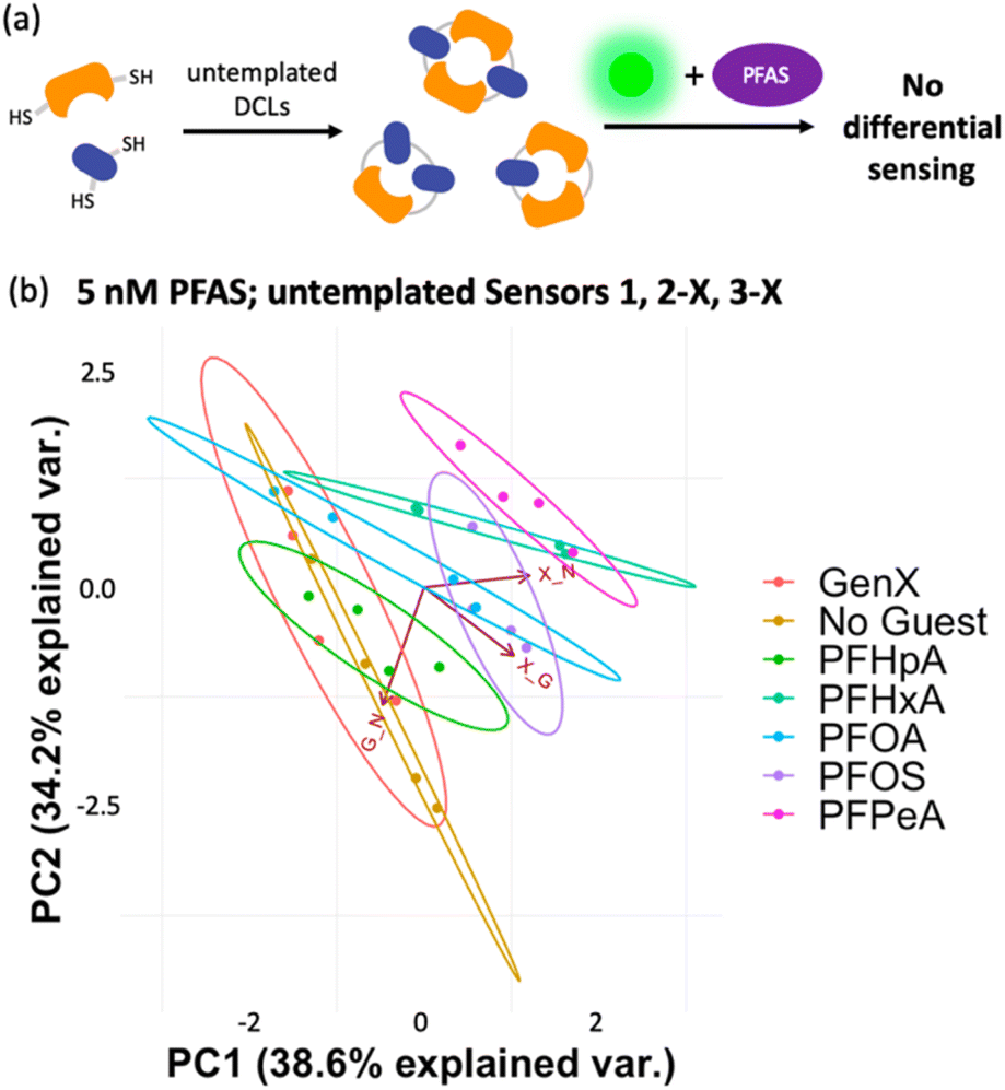 | ||
| Fig. 9 (a) Cartoon representing the workflow of the assay using untemplated DCLs. (b) PCA plot (95% confidence) displaying lack of differentiation of six individual PFAS and a No Guest sample in 50 mM sodium borate buffer (pH 8.5) using the untemplated sensors 1, 2-X, and 3-X (G + N, X + G, and X + N DCLs), to which PFAS and LCG were added simultaneously. | ||
After confirming the functionality of the PFAS sensor array and validating the role of the DCLs, we assessed the ability of the array to discriminate mixtures of PFAS at the same total concentration. While it is often important to detect simply whether PFAS contamination is present in a water sample, in some cases it is useful to understand what specific PFAS are present, since they each have different toxicity and persistence profiles. Thus, we first evaluated application of the array using a simple set of mixtures with different numbers of PFAS components and thus varying levels of mixture complexity (Table 1). We achieved full separation of these mixtures, including a No Guest sample, at 20 nM total PFAS (Fig. 10). However, most separation, notably from the No Guest sample, is lost when the PFAS concentration is lowered to 10 nM (Fig. S13†). Thus, at a total PFAS concentration of 20 nM, the imprint-and-report system is sensitive enough to provide differential signal for mixtures containing different PFAS components.
| Mixture name | Mixture components |
|---|---|
| Binary | PFOS, PFOA |
| Ternary | PFOS, PFOA, PFHxA |
| Quaternary | PFOS, PFOA, PFHxA, GenX |
| Quinary | PFOS, PFOA, PFHxA, GenX, PFPeA |
| Senary | PFOS, PFOA, PFHxA, GenX, PFPeA, PFHpA |
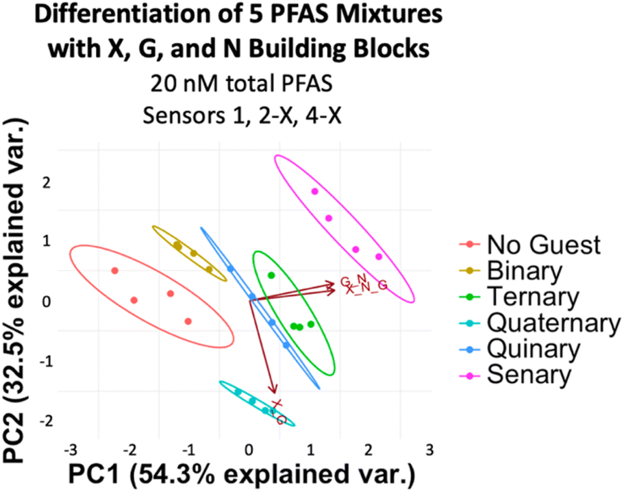 | ||
| Fig. 10 PCA plot displaying detection of five PFAS mixtures in 50 mM sodium borate buffer (pH 8.5) varying in number of components (according to Table 1) and a No Guest sample using sensors 1, 2-X, and 4-X (G + N, X + G, and X + G + N DCLs) at 20 nM total PFAS. PCA plots are shown with 95% confidence ellipses. | ||
To assess more complex PFAS mixtures, we evaluated a set based on the PFAS composition of some of the most highly contaminated areas of North Carolina: Mebane, Raeford, Ramseur, Wallace, and Sanford. We made mixtures representing the ratios found in Mebane, Raeford, Ramseur, and Wallace at a total PFAS concentration of 20 nM, while the Sanford mixture was made to have 4.5 times the total PFAS concentration of the others to reflect the especially high PFAS levels detected in Sanford (Table 2).49 Analysis of the array data indicates that we again achieved full separation of the mixtures at 20 nM total PFAS (or 90 nM for the Sanford sample) and the No Guest sample (Fig. 11). While some separation is maintained at 10 nM PFAS (45 nM Sanford sample), slight overlap is observed between Ramseur and Wallace and between No Guest and Mebane (Fig. S15†). This means a PFAS-free sample may not always be confidently distinguished from a PFAS-contaminated sample using this array at 10 nM PFAS.
| Area | Total [PFAS]rel | PFAS species | Ratio |
|---|---|---|---|
| Mebane | 1 | PFOS, PFOA, PFHxA, PFPeA | 1![[thin space (1/6-em)]](https://www.rsc.org/images/entities/char_2009.gif) :1:2:19 :1:2:19 |
| Raeford | 1 | PFHxA, PFPeA, PFHxS, PFBS, PFOS | 1:1:6:8:12 |
| Ramseur | 1 | PFPeA | — |
| Sanford | 4.5 | PFOA, PFHxS, PFOS, PFPeA, PFHpA, PFHxA | 1:2:91:11:11:6 |
| Wallace | 1 | PFOS, PFPeA | 1:25 |
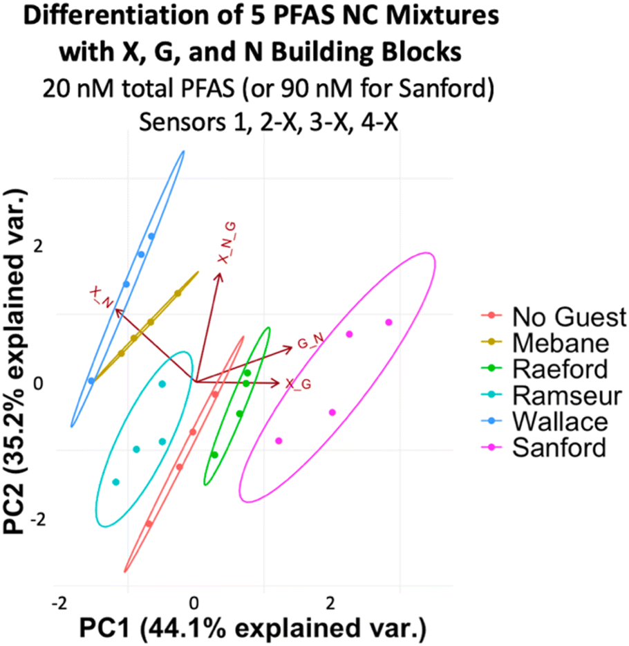 | ||
| Fig. 11 PCA plot displaying detection of five PFAS mixtures in 50 mM sodium borate buffer (pH 8.5) varying in components, ratios, and total concentration (according to Table 2) and a No Guest sample using sensors 1, 2-X, 3-X, and 4-X (G + N, X + G, X + N, and X + G + N DCLs) at 20 nM total PFAS (or 90 nM for the Sanford Sample). PCA plots are shown with 95% confidence ellipses. | ||
To evaluate if the imprint-and-report sensor array can also function in tap water samples, we created the same set of mixtures corresponding to NC areas by spiking tap water from UNC's campus with the PFAS. We also included a sample of unspiked milliQ water and a sample of unspiked UNC tap water as controls. We found that at total PFAS concentrations of 40 nM (180 nM Sanford sample), no separation of the 40 nM mixtures from each other is observed. The array likely loses sensitivity in tap water compared to buffer due to the greater complexity of the background. However, the PCA plot still provides a useful analysis of the samples, as it successfully separates the milliQ water, the unspiked tap water, the 40 nM PFAS mixtures (Mebane, Raeford, Ramseur, and Wallace), and the 180 nM Sanford mixture (Fig. 12a), demonstrating that it can differentiate variation in total PFAS concentrations, even when the composition of the PFAS compounds varies. Moreover, the assay was repeated on a different day with fresh tap water and showed a reproducible trend; the data sets from both days also overlay well when combined into one plot (Fig. 12b and c).
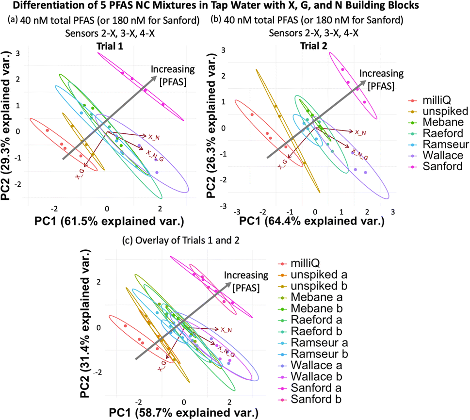 | ||
| Fig. 12 (a) PCA plots displaying detection of five PFAS mixtures varying in components, ratios, and total concentration (according to Table 2) in tap water, as well as a non-spiked tap water sample and a milliQ sample using sensors 2-X, 3-X, and 4-X (X + G, X + N, and X + G + N DCLs) at 40 total PFAS (or 180 nM for Sanford). (b) A second trial performed with a fresh tap water sample shows a reproducible trend, and (c) both trials overlay when combined into one PCA plot. All PCA plots are shown with 95% confidence ellipses. | ||
Once again, analysis of the ellipses provides insight into the function of the sensor array. The ellipses in Fig. 12 trend diagonally towards the upper right corner of the plot as the PFAS concentration increase. The X + G DCL vector (sensor 2-X) is positioned along this diagonal, suggesting that sensor 2-X is most responsible for differentiating these samples in tap water. Perpendicular to the direction of the sample detection, PC1 and PC2 together capture data point scatter that is aligned closely with the X + G + N DCL vector (sensor 4-X) and somewhat with the X + N vector (sensor 3-X). This reflects the larger error within the data sets originating from sensors 3-X and 4-X, possibly due to a larger amount of interference by background species in the tap water with the receptors in these sensors.
Conclusions
We have demonstrated herein that an imprint-and-report fluorescent sensor array comprised of three simple building blocks (X, G, and N) and their four corresponding DCLs generates a fluorescent PFAS detection and differentiation system that provides a new state of the art in fluorescence sensing of this class of compounds. The array is able to fully distinguish between six individual PFAS that are prominent environmental contaminants at 5 nM, as well as two sets of PFAS mixtures at 20 nM, one set that varies in the number of PFAS components and one that is based on environmental contamination components and ratios in several locations in NC. Further, we show that the array is able to differentiate mixtures containing different concentrations of spiked PFAS contamination in tap water. While this 5–20 nM PFAS concentration range is still higher than environmental PFAS contamination levels in real water samples (i.e. non-spiked tap water, lake water, etc.), the imprint-and-report system nonetheless represents the most sensitive fluorescence detection system that has been developed to our knowledge, with the widest scope of detection with respect to different PFAS and mixtures. This proof-of-principle study suggests that further optimization of the DCLs with additional fluorinated building blocks or positively charged moieties to strengthen interactions with the PFAS will increase the sensitivity and applicability of the array.Data availability
The datasets supporting this article have been uploaded as part of the ESI.†Author contributions
M. L. W. and E. E. H. conceived of the research. M. L. W. acquired funding. E. E. H. conducted the research and wrote the original draft of the manuscript. M. L. W. edited the manuscript.Conflicts of interest
There are no conflicts to declare.Acknowledgements
This material is based upon work supported by the National Science Foundation (CHE-2107685), the UNC Collaboratory, and the NC General Assembly.References
- A. B. Lindstrom, M. J. Strynar and E. L. Libelo, Environ. Sci. Technol., 2011, 45(19), 7954–7961 CrossRef CAS PubMed.
- E. S. Baker and D. R. U. Knappe, Anal. Bioanal. Chem., 2022, 414, 1187–1188 CrossRef PubMed.
- M. Sun, E. Arevalo, M. Strynar, A. Lindstrom, M. Richardson, B. Kearns, A. Pickett, C. Smith and D. R. U. Knappe, Environ. Sci. Technol. Lett., 2016, 3(12), 415–419 CrossRef CAS.
- J. S. Boone, C. Vigo, T. Boone, C. Byrne, J. Ferrario, R. Benson, J. Donohue, J. E. Simmons, D. W. Kolpin and E. T. Furlong, Sci. Total Environ., 2019, 653, 359–369 CrossRef CAS PubMed.
- F. Xiao, Water Res., 2017, 124, 482–495 CrossRef CAS PubMed.
- X. C. Hu, D. Q. Andrews, A. B. Lindstrom, T. A. Bruton, L. A. Schaider, P. Grandjean, R. Lohmann, C. C. Carignan, A. Blum and S. A. Balan, Environ. Sci. Technol. Lett., 2016, 3(10), 344–350 CrossRef CAS PubMed.
- G. B. Post, P. D. Cohn and K. R. Cooper, Environ. Res., 2012, 116, 93–117 CrossRef CAS PubMed.
- H. D. Whitehead, M. Venier, Y. Wu, E. Eastman, S. Urbanik, M. L. Diamond, A. Shalin, H. Schwartz-Narbonne, T. A. Bruton, A. Blum, Z. Wang, M. Green, M. Tighe, J. T. Wilkinson, S. McGuinness and G. F. Peaslee, Environ. Sci. Technol. Lett., 2021, 8(7), 538–544 CrossRef CAS.
- X. Trier, K. Granby and J. H. Christensen, Environ. Sci. Pollut. Res., 2011, 18, 1108–1120 CrossRef CAS PubMed.
- D. Herzke, E. Olsson and S. Posner, Chemosphere, 2012, 88(8), 980–987 CrossRef CAS PubMed.
- X. Dauchy, V. Boiteux, C. Bach, C. Rosin and J. F. Munoz, Chemosphere, 2017, 183, 53–61 CrossRef CAS PubMed.
- J. Glüge, M. Scheringer, I. T. Cousins, J. C. DeWitt, G. Goldenman, D. Herzke, R. Lohmann, C. A. Ng, X. Trier and Z. Wang, Environ. Sci.: Processes Impacts, 2020, 22, 2345–2373 RSC.
- M. Kotthoff, J. Müller, H. Jürling, M. Schlummer and D. Fiedler, Environ. Sci. Pollut. Res., 2015, 22(19), 14546–14559 CrossRef CAS PubMed.
- S. E. Fenton, A. Ducatman, A. Boobis, J. C. DeWitt, C. Lau, C. Ng, J. S. Smith and S. M. Roberts, Environ. Toxicol. Chem., 2021, 40(3), 606–630 CrossRef CAS PubMed.
- I. Quaak, M. de Cock, M. de Boer, M. Lamoree, P. Leonards and M. van de Bor, Int. J. Environ. Res. Public Health, 2016, 13(5), 511 CrossRef PubMed.
- A. Kataria, H. Trachtman, L. Malaga-Dieguez and L. Trasande, Environ. Health, 2015, 14(1), 89 CrossRef PubMed.
- V. Barry, A. Winquist and K. Steenland, Environ. Health Perspect., 2013, 121(11–12), 1313–1318 CrossRef PubMed.
- D. Melzer, N. Rice, M. H. Depledge, W. E. Henley and T. S. Galloway, Environ. Health Perspect., 2010, 118(5), 686–692 CrossRef CAS PubMed.
- E. T. Chang, H. O. Adami, P. Boffetta, H. J. Wedner and J. S. Mandel, Crit. Rev. Toxicol., 2016, 46(4), 279–331 CrossRef CAS PubMed.
- P. Grandjean, E. Andersen, E. Budtz-Jørgensen, F. Nielsen, K. Mølbak, P. Weihe and C. Heilmann, JAMA, J. Am. Med. Assoc., 2012, 307(4), 391–397 CrossRef CAS PubMed.
- J. L. Butenhoff, S. C. Chang, D. J. Ehresman and R. G. York, Reprod. Toxicol., 2009, 27(3), 331–341 CrossRef CAS PubMed.
- M. Strynar, S. Dagnino, R. McMahen, S. Liang, A. Lindstrom, E. Andersen, L. McMillan, M. Thurman, I. Ferrer and C. Ball, Environ. Sci. Technol., 2015, 49(19), 11622–11630 CrossRef CAS PubMed.
- Human Health Toxicity Values for Hexafluoropropylene Oxide (HFPO) Dimer Acid and Its Ammonium Salt (CASRN 13252-13-6), EPA, 2018 Search PubMed.
- Fact Sheet: Human Health Toxicity Assessment for GenX Chemicals, EPA, 2021 Search PubMed.
- S. Jia, M. Marques Dos Santos, C. Li and S. A. Snyder, Anal. Bioanal. Chem., 2022, 414, 2795–2807 CrossRef CAS PubMed.
- J. N. Dodds, Z. R. Hopkins, D. R. U. Knappe and E. S. Baker, Anal. Chem., 2020, 92, 4427–4435 CrossRef CAS PubMed.
- J. McCord and M. Strynar, Environ. Sci. Technol., 2019, 53(9), 4717–4727 CrossRef CAS PubMed.
- N. Yamashita, K. Kannan, S. Taniyasu, Y. Horii, T. Okazawa, G. Petrick and T. Gamo, Environ. Sci. Technol., 2004, 38, 5522–5528 CrossRef CAS PubMed.
- J. Shoemaker and D. Tettenhorst, Method 537.1: Determination of Selected Per-and Polyfluorinated Alkyl Substances in Drinking Water by Solid Phase Extraction and Liquid Chromatography/Tandem Mass Spectrometry (LC/MS/MS), US Environmental Protection Agency, Office of Research and Development, 2018 Search PubMed.
- T. Sanan and M. Magnuson, J. Chromatogr., A, 2020, 1626, 461324 CrossRef CAS PubMed.
- M. M. Mann, J. D. Tang and B. W. Berger, Biotechnol. Bioeng., 2021, 119(2), 513–522 CrossRef PubMed.
- J. Park, K. Yang, Y. Choi and J. K. Choe, Environ. Int., 2022, 158, 107000 CrossRef CAS PubMed.
- Z. Cheng, L. Du, P. Zhu, Q. Chen and K. Tan, Spectrochim. Acta, Part A, 2018, 201, 281–287 CrossRef CAS PubMed.
- L. Zheng, Y. Zheng, Y. Lui, S. Long, L. Du, J. Liang, C. Huang, M. T. Swihart and K. Tan, Talanta, 2019, 194, 1–6 CrossRef CAS PubMed.
- Q. Liu, A. Huang, N. Wang, G. Zheng and L. Zhu, J. Lumin., 2015, 161, 374–381 CrossRef CAS.
- C. Fang, J. Wu, Z. Sobhani, M. Amin and Y. Tang, Anal. Methods, 2019, 11, 163–170 RSC.
- Z. Zheng, H. Yu, W. C. Geng, X. Y. Hu, Y. Y. Wang, Z. Li, Y. Wang and D. S. Guo, Nat. Commun., 2019, 10, 5762 CrossRef CAS PubMed.
- L. You, D. Zha and E. V. Anslyn, Chem. Rev., 2015, 115(15), 7840–7892 CrossRef CAS PubMed.
- J. J. Lavigne and E. V. Anslyn, Angew. Chem., Int. Ed., 2001, 40, 3118–3130 CrossRef CAS PubMed.
- Y. Geng, W. J. Peveler and V. Rotello, Angew. Chem., Int. Ed., 2019, 58(16), 5190–5200 CrossRef CAS PubMed.
- Z. Li, J. R. Askim and K. S. Suslick, Chem. Rev., 2019, 119(1), 231–292 CrossRef CAS PubMed.
- B. Chen, Z. Yang, X. Qu, S. Zheng, D. Yin and H. Fu, ACS Appl. Mater. Interfaces, 2021, 13, 47706–47716 CrossRef CAS PubMed.
- M. Yin, L. Che, S. Jiang, Q. Deng and S. Wang, Environ. Sci.: Nano, 2020, 7, 3036–3046 RSC.
- J. Lever, M. Krzywinski and N. Altman, Nat. Methods, 2017, 14(7), 641–642 CrossRef CAS.
- S. Stewart, M. A. Ivy and E. V. Anslyn, Chem. Soc. Rev., 2014, 43, 70–84 RSC.
- P. T. Corbett, J. Leclaire, L. Vial, K. R. West, J. L. Wietor, J. K. M. Sanders and S. Otto, Chem. Rev., 2006, 106(9), 3652–3711 CrossRef CAS PubMed.
- E. E. Harrison, B. A. Carpenter, L. E. St. Louis, A. G. Mullins and M. L. Waters, J. Am. Chem. Soc., 2021, 143(36), 14845–14854 CrossRef CAS PubMed.
- E. E. Harrison and M. L. Waters, Angew. Chem., Int. Ed., 2022, 134(33), e202205193 CrossRef.
- Emerging Compounds Mastersheet, North Carolina Department of Environmental Quality, 2019 Search PubMed.
- L. Vial, R. F. Ludlow, J. Leclaire, R. Perez-Fernandez and S. Otto, J. Am. Chem. Soc., 2006, 128(31), 10253–10257 CrossRef CAS PubMed.
- K. R. West, R. F. Ludlow, P. T. Corbett, P. Besenius, F. M. Mansfeld, P. A. G. Cormack, D. C. Sherrington, J. M. Goodman, M. C. A. Stuart and S. Otto, J. Am. Chem. Soc., 2008, 130(33), 10834–10835 CrossRef CAS PubMed.
- N. K. Pinkin and M. L. Waters, Org. Biomol. Chem., 2014, 12, 7059–7067 RSC.
- R. Pollice and P. Chen, J. Am. Chem. Soc., 2019, 141(8), 3489–3506 CrossRef CAS PubMed.
- X. Tan, M. Sawczyk, Y. Chang, Y. Wang, A. Usman, C. Fu, P. Král, H. Peng, C. Zhang and A. K. Whittaker, Macromolecules, 2022, 55, 1077–1087 CrossRef CAS.
- E. Kumarasamy, I. M. Manning, L. B. Collins, O. Coronell and F. A. Leibfarth, ACS Cent. Sci., 2020, 6(4), 487–492 CrossRef CAS PubMed.
- S. Kawahara, S. Tsuzuki and T. Uchimaru, J. Phys. Chem. A, 2004, 108(32), 6744–6749 CrossRef CAS.
- P. T. Skowron, M. Dumartin, E. Jeamet, F. Perret, C. Gourlaouen, A. Baudouin, B. Fenet, J. V. Naubron, F. Fotiadu, L. Vial and J. Leclaire, J. Org. Chem., 2016, 81, 654–661 CrossRef CAS PubMed.
Footnote |
| † Electronic supplementary information (ESI) available: Synthesis and characterization, sensor preparation sensor array assay methods, principal component analysis, sensor array results, fluorescence data. See DOI: https://doi.org/10.1039/d2sc05685b |
| This journal is © The Royal Society of Chemistry 2023 |