 Open Access Article
Limiting voltage and capacity fade of lithium-rich, low cobalt Li1.2Ni0.13Mn0.54Fe0.1Co0.03O2 by controlling the upper cut-off voltage
Nabil El Halya,
Mohamed Kerroumi,
El Houcine Elmaataouy ,
Amina Amarray,
Mohamed Aqil,
Jones Alami and
Mouad Dahbi
 *
*
Materials Science and Nano-engineering Department, Mohammed VI Polytechnic University, Ben Guerir, Morocco. E-mail: Mouad.dahbi@um6p.ma
First published on 24th November 2023
Abstract
A new Li1.2Ni0.13Mn0.54Fe0.1Co0.03O2 material with a higher content of Fe and lower content of Co was designed via a simple sol–gel method. Moreover, the effect of upper cut-off voltage on the structural stability, capacity and voltage retention was studied. The Li1.2Ni0.13Mn0.54Fe0.1Co0.03O2 electrode delivers a discharge capacity of 250 mA h g−1 with good capacity retention and coulombic efficiency at 4.6 V cut-off voltage. Importantly, improved voltage retention of 94% was achieved. Ex situ XRD and Raman proved that the electrodes cycled at 4.8 V cut-off voltage showed huge structural conversion from layered-to-spinel explaining the poor capacity and voltage retention at this cut-off voltage. In addition, ex situ FT-IR demonstrates that the upper cut-off voltage of 4.8 V exhibits a higher intensity of SEI-related peaks than 4.6 V, suggesting that reducing the upper cut-off voltage can inhibit the growth of the SEI layer. In addition, when the Li1.2Ni0.13Mn0.54Fe0.1Co0.03O2 cathode was paired with a synthesized phosphorus-doped TiO2 anode (P-doped TiO2) in a complete battery cell, it exhibits good capacity and cycling stability at 1C rate. The material developed in this study represents a promising approach for designing high-performance Li-rich, low cobalt cathodes for next-generation lithium-ion batteries.
Introduction
In recent years, lithium-ion batteries have been widely applied in portable electronic devices such as cellular phones, laptops, and power tools due to their high energy density, low self-discharge, and tiny memory effect.1–3 However, LiCoO2, the first commercially available cathode material, is plagued by high costs, toxicity, and safety concerns. Other similar layered structure materials, such as LiNiO2, LiMnO2, and LiMn2O4 have been extensively studied as prospective cathode materials.4–6 Nevertheless, several problems must be addressed. The synthesis of LiNiO2 has been found to be challenging, and its capacity decreases rapidly due to the formation of the NiO2 phase.7–9 Moreover, at higher temperatures, the exothermic decomposition of LiNiO2 in the charged state causes safety issues. In addition, LiMnO2 is thermodynamically unstable and tends to convert rapidly to LiMn2O4 during cycling.10,11 LiMn2O4 also suffers from severe capacity fading at high temperatures due to the Jahn-Teller distortion of Mn3+, Mn ions' dissolution in electrolyte and the formation of two cubic phases and growth of microstrain.10,12,13 One of the most common alternatives has been lithium nickel cobalt manganese oxides Li(NiMnCo)O2 (NMC) due to their relative low cost, high capacity, and better thermal stability.14 However, Li(NiMnCo)O2 has inherent disadvantages such as cation mixing, toxicity and high-capacity losses in the first discharge cycles.15,16 Therefore, the development of low-cost, non-toxic, and high-capacity cathode materials is needed. To improve the structural stability and the electrochemical performance of Li(NiMnCo)O2 based materials, various metal doping such as Al, Cr, Fe, Mo, Mg, Zr, and Si has been studied.17–22Recently, Layered lithium-rich NMC (Li-rich NMC) has been extensively studied due to its enhanced performances, especially the high discharge capacity (>250 mA h g−1).23–30 However, Li-rich NMC cathodes still suffer from serious drawbacks such as the poor rate capabilities and the non-stable electrochemical performances (capacity and voltage fading) caused by the transition metals leaching during cycling and the crystal structures changes. Besides, there is the degradation of the different components of the electrodes such as the binder, conductive additive, and the electrolyte. Several strategies have been adopted to stabilize the crystal structure and decrease the voltage and capacity drop of Li-rich NMC cathode material including surface coating,31–36 doping,29,37–45 structural modification,46–53 lithium extraction,54–57 and electrolyte modification.58–64
Controlling the cut-off voltage can be also an effective strategy for stabilizing the crystal structure and decreasing the capacity and voltage drop of Li-rich NMC cathode materials.65–70 The conventional cycling protocol typically extends the upper cut-off voltage to 4.8 V to achieve higher capacities, however this causes huge structural instability and voltage drop. By setting the upper cut-off voltage to a lower value, the material is not fully charged and remains partially discharged, which can help to stabilize the crystal structure and reduce the voltage drop. This is because the material can maintain a higher average oxidation state, which can reduce the formation of unwanted side reactions and increase the overall stability of the material.67,69,70
Here, a new Li-rich Li1.2 Mn0.54Ni0.13Fe0.1Co0.03O2 (NMCF) cathode material with higher content of Fe and lower content of Co was prepared via a simple sol–gel method. Moreover, the effect of upper cut-off voltage on the capacity and voltage retention of NMCF during charge/discharge cycling was identified. According to our findings, NMCF electrodes undergo phase changes at high charge voltage (4.8 V). Nonetheless, the electrode cycled at a moderate voltage range of 4.6 V displayed enhanced structural stability, as well as low capacity and voltage fading during repeated cycling. By restricting the upper cut-off voltage to lower values, the present study aims to limit the structural rearrangements that cause the capacity and voltage fade and ensure more cycling stability during prolonged charge/discharge cycling.
Experimental
Synthesis of NMCF material
NMCF material was synthesized using a simple sol–gel route. Stoichiometric amount of LiCH3COO·2H2O (with an excess of 5 wt%) (99% Sigma Aldrich), C4H6MnO4·4H2O (99% Sigma Aldrich), C4H6NiO4·4H2O (99% Sigma Aldrich), C4H6CoO4·4H2O (99% Sigma Aldrich), and FeC2O4·2H2O (99% Sigma Aldrich), were mixed in distilled water with citric acid (C6H8O7, 99% Sigma Aldrich), as a chelating agent (molar ratio of citric acid to total metal ions is 1![[thin space (1/6-em)]](https://www.rsc.org/images/entities/char_2009.gif) :
:![[thin space (1/6-em)]](https://www.rsc.org/images/entities/char_2009.gif) 1.2). The pH of the solution was adjusted to 9 using a solution of 0.2 M ammonia. Subsequently, the solution was placed in a water bath at 80 °C and stirred until the formation of a wet gel. The gel was further dried overnight at 120 °C, ground and then calcined at 850 °C for 5 h in an air atmosphere to obtain Li1.2Mn0.54Ni0.13Fe0.1Co0.03O2 powder.
1.2). The pH of the solution was adjusted to 9 using a solution of 0.2 M ammonia. Subsequently, the solution was placed in a water bath at 80 °C and stirred until the formation of a wet gel. The gel was further dried overnight at 120 °C, ground and then calcined at 850 °C for 5 h in an air atmosphere to obtain Li1.2Mn0.54Ni0.13Fe0.1Co0.03O2 powder.
Electrochemical measurements
NMCF electrodes were prepared by mixing 85% wt of active material, 10% wt of carbon black (Sigma Aldrich) and 5% wt of PVDF (Sigma Aldrich) binder. The mixture was dissolved in N-methyl-2-pyrrolidone (NMP, 99.5%, Sigma Aldrich) and casted onto Al current collector using doctor blade. The casting was air dried in oven at 70 °C and punched into circular disks. The coin cells were assembled in an Ar-filled glovebox using lithium foil as counter electrodes, WHATMAN glass microfiber filter as separator and 1 M LiPF6 in EC![[thin space (1/6-em)]](https://www.rsc.org/images/entities/char_2009.gif) :
:![[thin space (1/6-em)]](https://www.rsc.org/images/entities/char_2009.gif) DMC (1
DMC (1![[thin space (1/6-em)]](https://www.rsc.org/images/entities/char_2009.gif) :
:![[thin space (1/6-em)]](https://www.rsc.org/images/entities/char_2009.gif) 1) as electrolyte. For Full Cell measurement, P-doped TiO2 (synthesis process and electrochemical performances are details in our recent studies71,72) was used as negative electrode. This electrode was composed of 85% wt of P-doped TiO2 active material, 10% wt of carbon black, and 5% wt PVDF. The N/P mass ratio was about 1.12. A dis/charge rate of 1C was applied, which corresponds to a specific current of 200 mA g−1 for the positive electrode material.
1) as electrolyte. For Full Cell measurement, P-doped TiO2 (synthesis process and electrochemical performances are details in our recent studies71,72) was used as negative electrode. This electrode was composed of 85% wt of P-doped TiO2 active material, 10% wt of carbon black, and 5% wt PVDF. The N/P mass ratio was about 1.12. A dis/charge rate of 1C was applied, which corresponds to a specific current of 200 mA g−1 for the positive electrode material.
Materials characterizations
The synthesized samples were characterized by a powder X-ray diffractometer (Bruker D8 Advance powder) using an incident X-ray beam coming from a copper anticathode with a wavelength λ = 1.54060 Å of Kα1 and λ2 = 1.54439 Å of Kα2. The samples' morphology and structure were recorded by a field emission scanning electron microscope (ZEISS EVO (SEM) from Carl Zeiss Microscopy) and high-resolution Raman microscopes (Lab RAM HR Evolution Raman microscopes). Chemical bonding of NMCF electrodes after cycling were identified using Fourier transform infrared spectroscopy (FTIR, PerkinElmer Spectrometer). For the electrochemical measurements, cyclic voltammetry at different scan rates, charge–discharge tests, and electrochemical impedance spectroscopy (form 100 kHz to 10 mHz) were performed using a biologic battery tester within two potential window 2.5–4.6 V and 2.5–4.8 V.Results and discussion
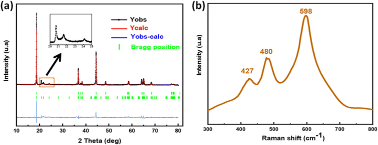
NMCF powder was characterized by X-ray diffraction as shown in Fig. 1a, followed by Rietveld refinement. All diffraction peaks can be indexed to a typical hexagonal–NaFeO2 layered structure with R![[3 with combining macron]](https://www.rsc.org/images/entities/char_0033_0304.gif) m space group, except the weak peaks at around 2θ = 20–25° which are attributed to the Li2MnO3 component (monoclinic structure with space group C2/m). These diffractions are relevant to the LiM6 cation ordering that occurs in the transition metal layers of Li2MnO3. The reliability factors (Rp (%): 8.65, Rwp (%): 9.21, Rexp (%): 10.34 and χ2: 1.02) provide strong evidence that both structural types align effectively with the peaks in the calculated pattern and are in excellent agreement with the observed data. Other impurity peaks were not observed, indicating that the material was successfully synthesized with better crystallinity and pure phase content. Furthermore, the I(003)/I(104) ratio was 1.3, which indicates that the materials have excellent cation ordering (low amount of Li+ and Ni2+ disordering). Tables 1 and 2 provide the structural parameters of Li2MnO3 and LiNi0.13Mn0.54Fe0.1Co0.03O2, which together form the material NMCF. The parameters were compared to those of other Li-rich layered materials with similar stoichiometry that have been previously reported in literature.
m space group, except the weak peaks at around 2θ = 20–25° which are attributed to the Li2MnO3 component (monoclinic structure with space group C2/m). These diffractions are relevant to the LiM6 cation ordering that occurs in the transition metal layers of Li2MnO3. The reliability factors (Rp (%): 8.65, Rwp (%): 9.21, Rexp (%): 10.34 and χ2: 1.02) provide strong evidence that both structural types align effectively with the peaks in the calculated pattern and are in excellent agreement with the observed data. Other impurity peaks were not observed, indicating that the material was successfully synthesized with better crystallinity and pure phase content. Furthermore, the I(003)/I(104) ratio was 1.3, which indicates that the materials have excellent cation ordering (low amount of Li+ and Ni2+ disordering). Tables 1 and 2 provide the structural parameters of Li2MnO3 and LiNi0.13Mn0.54Fe0.1Co0.03O2, which together form the material NMCF. The parameters were compared to those of other Li-rich layered materials with similar stoichiometry that have been previously reported in literature.
| Structure | a (Å) | b (Å) | c (Å) | c/a | Ref. |
|---|---|---|---|---|---|
| Li1.2Mn0.54Ni0.13Fe0.1Co0.03O2 | 2.863 | 2.863 | 14.277 | 4.986 | This work |
| Li1.2Mn0.56Ni0.16Co0.08O2 | 2.866 | 2.866 | 14.304 | 4.990 | 74 |
The Raman spectra are presented in Fig. 1b. The two significant Raman bands appearing at around 594 and 474 cm−1 in the spectra results from the stretching A1g modes (originate from the O–M–O bending vibrations) and bending Eg (originate from the M–O symmetrical stretching), respectively. An additional small Raman band at 424 cm−1 could be attributed to the monoclinic Li2MnO3 phase. This result proves that the prepared material has an excellent layered structure with a R![[3 with combining macron]](https://www.rsc.org/images/entities/char_0033_0304.gif) m symmetry.75
m symmetry.75
Scanning Electron Microscopy (SEM) images of NMCF samples with different magnification levels are shown in Fig. 2a. The NMCF powder appear as homogeneous round-like particles with submicron-size in the range of 150–400 nm. This morphology shortens the migration paths of Li ions by offering an adequate contact between the material and electrolyte. Fig. 2b and c shows the Energy-Dispersive X-ray (EDX) elemental mapping analysis and the EDX spectrum of NMCF material. The sample contains Ni, Co, Mn, Fe and O elements with no other impurities. Moreover, Mn, Co, Ni, Fe, and O atoms are uniformly distributed on the surface of NMCF powder.
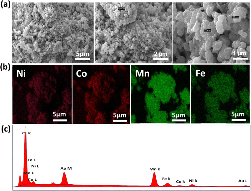 | ||
| Fig. 2 SEM images (a), Energy-Dispersive X-ray (EDX) elemental mapping analysis (b), EDX spectrum of NMCF material (c). | ||
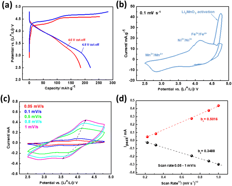
Fig. 3a depicts the initial charge–discharge curves of NMCF electrodes at a current density of 0.1C rate (1C = 200 mA g−1) within the voltage ranges of 2.0–4.6 V and 2.0–4.8 V. Both charge curves exhibit the features of layered Li-rich cathodes. The slope observed at 4.5 V is attributed to the process of lithium disinsertion from the LiMnxNiyFezCo1−x−y−zO2 component of Li1.2Mn0.54Ni0.13Fe0.1Co0.03O2, along with the oxidation of Ni2+ to Ni4+ and Co3+ to Co4+. The plateau observed at 4.5 V is due to the activation of the Li2MnO3 phase and the extraction of Li2O, which result in irreversible capacity loss. Moreover, compared to the electrode cycled under a cut-off voltage of 4.6 V, the electrode cycled under 4.8 V exhibits a higher discharge capacity of 220.5 mA h g−1 due to its fast activation in the initial charge process.
Cyclic voltammetry test of NMCF electrode was carried out within the voltage range of 2.5–4.8 V at 0.1 mV s−1 scan rates to evaluate the redox potential of metal ions (Fig. 3b). The strong anodic peak at 4.6 V is attributed to the activation reaction of Li2MnO3 that lead to oxygen release and remove Li2O from the Li2MnO3 component. This reaction disappears in the subsequent cycles. In addition, the anodic peak at 4.2 V corresponds to the oxidation reaction of Co3+, Fe3+ and Ni2+ ions to Co4+, Fe4+ and Ni4+.76 The cathodic peaks at ∼3.8 V, ∼2.8 V are due to the reduction of Ni4+/Fe4+/Co4+ to Ni2+/Fe3+/Co3+ and Mn4+ to Mn3+, respectively.77 Furthermore, cyclic voltammetry multi-rate was carried out to calculate the lithium-ions diffusion coefficient using the Randles–Sevcik equation:
| Ip = 2.69 × 10⁵An3/2C0D1/2v1/2 |
According to the results displayed in Fig. 3c and d, the calculated anodic and cathodic diffusion coefficients of NMCF electrode are 1.57, and 3.25 (×10−11 cm2 s−1), respectively. The obtained values agree with those reported in previous studies on the most advanced lithium-rich cathodes.78 This agreement suggests that the obtained results could lead to improved electrochemical performance.
The Li-rich materials are well known in the literature by their structural conversion from layered to spinel that occurs during prolonged cycling. This phenomenon results in a huge capacity and voltage fading.74,75 To clearly show this phase evolution during prolonged cycling, charge/discharge profiles and their differential capacity plots for 4.8 and 4.6 V cut-off voltages were plotted (Fig. 4a–d). Under both cut-off voltages, the NMCF electrode shows a peak at 3.3 V which is attributed to the reduction of Mn4+ to Mn3+. However, at 4.8 V cut-off voltage this peak shift to lower potentials after 100 cycles and a new peak appears at 2.8 V suggesting the formation of the spinel phase. More importantly, at 4.6 V, the peak corresponding to the spinel phase was not observed after 100 cycles expect the low shift to lower potentials which can be explained by the modification of the layered structure.79 Fig. 4e presents a comparison of the average discharge voltages at the cut-off voltages of 4.6 V and 4.8 V. Notably, the discharge average voltage at the 4.6 V cut-off voltage is observed to be higher than that at the 4.8 V cut-off voltage. Furthermore, after 100 cycles, the decrease in discharge voltage is significantly lower when the 4.6 V cut-off voltage is applied (94%) in contrast to the 4.8 V cut-off voltage (90%).
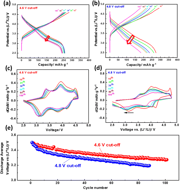 | ||
| Fig. 4 Galvanostatic discharge/charge curves (a and b), dQ/dV plots (c and d), discharge average voltage (e) of NMCF electrode cycled at C/10 under the cut-off voltages of 4.6 and 4.8 V. | ||
Fig. 5a displays the cycling performances and coulombic efficiencies of NMCF electrode cycled under 4.6 V and 4.8 V cut-off voltages to evaluate their galvanostatic charge/discharge properties. At C/10 rate, both electrodes exhibit two contrasting developing trends in terms of cycling performance. As the cycling progresses, the specific capacity of the electrode cycled under a cut-off voltage of 4.6 V gradually increases, with an initial discharge specific capacity of only 183.8 mA h g−1. Similarly, the specific capacity of the electrode cycled under 4.8 V cut-off voltage shows an increasing trend in the initial cycles, and after 10 cycles, a maximum discharge specific capacity of 289.2 mA h g−1 was achieved, which is closely associated with the gradual activation of the redox reaction. Moreover, under 4.6 V cut-off voltage a better cycling stability was achieved. Despite having a lower first discharge specific capacity of 183.8 mA h g−1, the electrode cycled under a cut-off voltage of 4.6 V exhibits higher cycling stability. Notably, compared to previous reports of Fe-based Li-rich materials,80–82 NMCF material displays a significantly higher discharge capacity of 238.6 mA h g−1 after 100 cycles. Moreover, due to the good capacity and voltage stability under the cut-off voltage of 4.6 V, NMCF electrode delivers an energy retention of 89% after 100 cycles at C/10 (Fig. 5b).
 | ||
| Fig. 5 Cycling performance and coulombic efficiency (a), calculated energy density (b) of NMCF electrodes cycled at C/10 under the cut-off voltages of 4.6 and 4.8 V. | ||
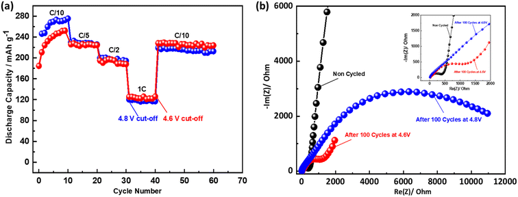
The rate capability of NMCF cathode under 4.6 V and 4.8 V cut-off voltages is shown in Fig. 6a. The NMCF electrodes display comparable reversible capacities under both cut-off voltages. Nevertheless, a lower discharge capacity was obtained for the electrode cycled under 4.8 V cut-off voltage when the rate recovers to C/10, indicating the low structural stability and the poor performance of the electrode cycled under a cut-off voltage of 4.8 V after high-rate cycling. These results prove that maintaining a cut-off voltage of 4.6 V is crucial for achieving stable capacity and voltage, as well as high-rate capability of NMCF cathode.
Electrochemical impedance spectroscopy (EIS) was used in a frequency range from 10 mHz to 10 MHz at room temperature in the discharged state ±2.5 to follow the evolution of charge transfer resistance during cycling (Fig. 6b). The widening of the semicircle observed at the cut-off 4.8 V, indicates that NMCF electrode has undergone accumulated severe defects. Jotti Karunawan et al. have attributed the increased charge transfer resistance to the cracks formation as well as the structural evolution from layered to spinel or rock salt.83 These results explain the poor electrochemical performance for the electrode cycled at 4.8 V.
To identify the effect of upper cut-off voltage on the structural stability of NMCF material upon cycling ex situ XRD was carried out. The XRD patterns of non-cycled and cycled electrodes at C/10 under 4.6 V and 4.8 V cut-off voltages are shown in Fig. 7a. After 100 cycles, the (003), (018) and (113) peaks become broader and weaker for both cut-off voltages indicating a decrease of the material crystallinity.84 Moreover, the two electrodes exhibit a noticeable shift towards lower 2θ angles of the most intense (003) reflection after cycling. This shift is also observed in other reflections, suggesting a lattice expansion along the c-axis. The increased repulsion of the transition metal layers caused by the irreversible loss of lithium after activation is the reason for this expansion. The (110) and (020) reflections, which are attributed to the Li2MnO3 phase, have disappeared after 100 cycles in both cut-off voltages which confirms the charge/discharge results. Furthermore, the I(003)/I(104) ratio after 100 cycles at C/10 was 1.01 for the electrode cycled under 4.6 V cut-off voltage compared to 0.90 for the electrode cycled under 4.8 V, which indicates that a large amount of transition-metal ions immigrate into the Li layers under 4.8 V cut-off voltage. In addition, the peak at 43.6° indicated the formation of the spinel structure. This peak is more intense for the electrode cycled under 4.8 V cut-off voltage. The obtained result proves that the cut-off voltage can be the major factor that control the structural stability of NMCF materials. In addition ex situ Raman spectroscopy was carried out to follow the structural evolution of NMCF cathode during cycling. Fig. 7b compares the Raman spectra of the non-cycled and cycled electrodes under 4.6 V and 4.8 V cut-off voltages after 100 cycles. The first Raman band at 423 cm−1 related to the Li2MnO3 phase is completely disappeared after cycling for both cut-off voltages which prove the result obtained by ex situ XRD. The other two Raman bands are shifted to higher values with significant decrease in the integral intensities indicating the structural changes upon cycling. These changes are clearer for the electrode cycled at 4.8 V comparing to 4.6 V. Thus, working at 4.6 V may suppress the phase transition observed for lithium-rich materials during cycling.
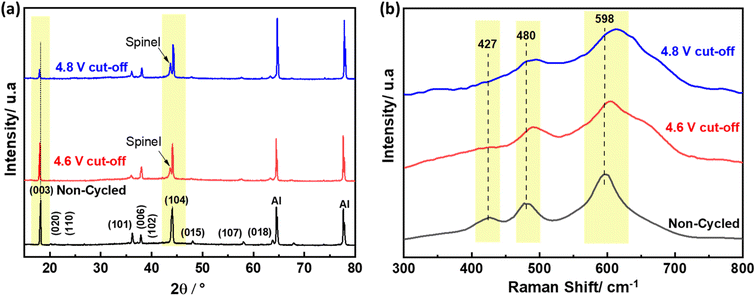 | ||
| Fig. 7 Ex situ XRD (a) and ex situ Raman (b) of NMCF electrodes after 100 cycles at C/10 under the cut-off voltages 4.6 V and 4.8 V. | ||
The effect of upper cut-off voltage on SEI formation was further examined using ex situ FTIR spectroscopy (Fig. 8). After 100 cycles, NMCF electrodes cycled at both upper cut-off voltages exhibit new absorption peaks in their FTIR spectra, which are attributed to SEI species present in the SEI layer. The SEI layer is composed of common species such as Li2CO3, ROCO2Li (lithium alkyl carbonate), and LixPOyFz (species containing fluoride and phosphate).85 It is important to note that non-cycled electrodes do not come in contact with electrolyte, and thus do not form the SEI layer on their surface. The peak at 875 cm−1 is present in all samples and is attributed to Li2CO3 impurity produced from the reaction between unreacted lithium salt and carbon dioxide on the surface of NMCF particles.86,87 The peak at 1412 cm−1 is assigned to the vibration of CO32−.87 Li2CO3 is one of the main SEI components formed on the surface of high voltage cathode materials during cycling. The C–H vibration peaks of ROCO2Li can be seen at 2850 and 2935 cm−1.88 Additionally, the vibration of COO− and C![[double bond, length as m-dash]](https://www.rsc.org/images/entities/char_e001.gif) O bindings related to ROCO2Li are observed at 1378 and 1630 cm−1, respectively. The Li–F vibrations of LixPOyFz can be observed at 1176 and 1288 cm−1.87 These results demonstrate that the cycled NMCF electrode at an upper cut-off voltage of 4.8 V exhibits a higher intensity of SEI-related peaks than that cycled at 4.6 V which agrees with the result obtained from electrochemical impedance spectroscopy. Overall, reducing the upper cut-off voltage can inhibit the growth of the SEI layer resulting in a lower charge transfer resistance.
O bindings related to ROCO2Li are observed at 1378 and 1630 cm−1, respectively. The Li–F vibrations of LixPOyFz can be observed at 1176 and 1288 cm−1.87 These results demonstrate that the cycled NMCF electrode at an upper cut-off voltage of 4.8 V exhibits a higher intensity of SEI-related peaks than that cycled at 4.6 V which agrees with the result obtained from electrochemical impedance spectroscopy. Overall, reducing the upper cut-off voltage can inhibit the growth of the SEI layer resulting in a lower charge transfer resistance.
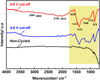 | ||
| Fig. 8 Ex situ FT-IR of NMCF electrodes after 100 cycles at C/10 under the cut-off voltages of 4.6 V and 4.8 V. | ||
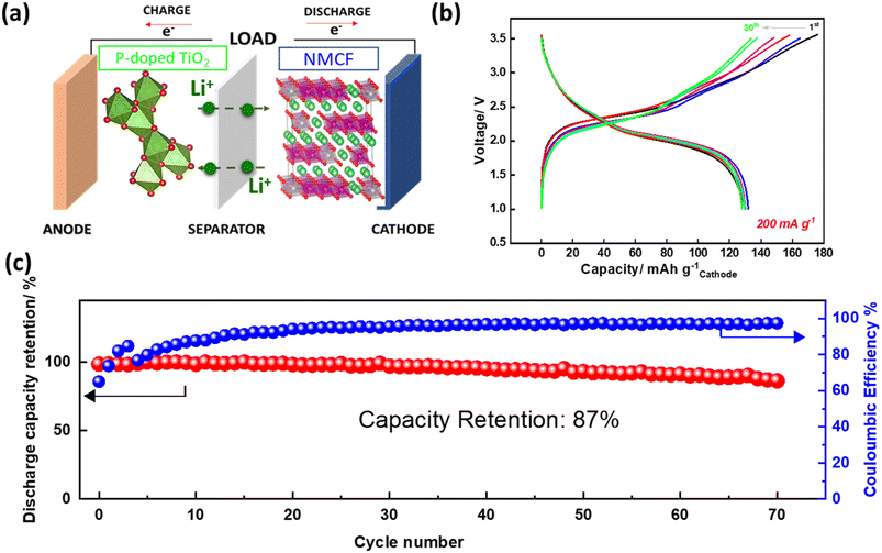
Finally, to evaluate the performance of NMCF material in a complete battery system, a full cell using P-doped TiO2 anode was designed (Fig. 9a). P-doped TiO2 has shown excellent first coulombic efficiency, lithium-ion diffusion, and capacity retention during prolonged cycling.72 The output voltage of the full cell was 2.3 V which match the voltage difference between P-doped TiO2 and NMCF. Moreover, Fig. 9b illustrates the charge/discharge cycles of the full cell at 1C current rate within the voltage window of 1–3.5 V. During the first cycle, the full cell exhibited a capacity of 130 mA h g−1, which is based on the mass of NMCF cathode. The cycling performance of the full cell (shown in Fig. 9c) was further investigated. After 70 cycles, a capacity retention of 87% was achieved at 1C. Additionally, the coulombic efficiency was observed to be 100%. The low capacity of NMCF electrode in the full cell is mainly due to its low first coulombic efficiency which does not exceed 70%. This low first coulombic efficiency of NMCF cathode could be attributed to several factors, including the decomposition of the electrolyte, the formation of a thick SEI layer, and the dissolution of transition metal ions from the cathode material. To overcome these issues, further works must be carried out, such as modifying the electrolyte composition, optimizing the electrode microstructure, and coating the NMCF cathode material with protective layers.
Conclusions
In summary, the present study was carried out to determine the effect of upper cut-off voltage on the structure stability, capacity retention and voltage retention of NMCF cathode material. This material was successfully synthesized by a simple sol–gel method. In addition, as confirmed by XRD Rietveld refinement, the prepared material has a hexagonal–NaFeO2 layered structure with excellent cation mixing. Besides, at 0.1C current rate, the electrode delivers good capacity retention and coulombic efficiency when using an upper cut-off voltage of 4.6 V. Importantly, a discharge voltage retention of 94% was obtained at this cut-off voltage. Ex situ XRD and Raman of the electrode cycled at C/10 were proved that the spinel phase occurs at both cut-off voltages, but is not dominant in 4.6 V. Besides ex situ FT-IR demonstrates that the upper cut-off voltage of 4.8 V exhibits a higher intensity of SEI-related peaks than 4.6 V, suggesting that reducing the upper cut-off voltage can inhibit the growth of the SEI layer and the surface corrosion of NMCF particles. Finally, NMCF cathode material was evaluated in a full cell using P-doped TiO2 anode. The output voltage of the full cell was 2.3 V with acceptable first capacity and capacity retention. The low capacity of NMCF electrode in the Full cell is mainly due to its low first coulombic efficiency which does not exceed 70%. The benefits of lithium-rich cathodes, including their high energy density, improved thermal stability, and lower cost, make them an attractive option for the future of battery technology. However, further research and development are needed to improve their first coulombic efficiency and overall performance.Author contributions
Nabil El Halya: idea conception, experimental investigation and writing of the original draft. Mohammed Kerroumi: formal analysis, experimental part, ElHoucine Elmaataouy: XRD measurement and Rietveld refinement, Amina Amarray: review and editing, Mouad Dahbi and Jones Alami: conceptualization, validation, review & editing, funding acquisition.Conflicts of interest
The authors declare that they have no known competing financial interests or personal relationships that could have appeared to influence the work reported in this paper.Acknowledgements
The authors would like to thank Office Chérifien des Phosphates (OCP S.A.) and Mohammed VI Polytechnic University for financial support.References
- Z. Guo, L. Li, Z. Su, G. Peng, M. Qu, Y. Fu, H. Wang and W. Ge, Electrochim. Acta, 2023, 437, 141525 CrossRef CAS.
- J. Liu, H. Yuan, X. Tao, Y. Liang, S. J. Yang, J. Huang, T. Yuan, M. Titirici and Q. Zhang, EcoMat, 2020, 2(1), e12019 CrossRef CAS.
- R. Razaq, N. Zhang, Y. Xin, Q. Li, J. Wang and Z. Zhang, EcoMat, 2020, 2(2), e12020 CrossRef CAS.
- R. Pan, E. Jo, Z. Cui and A. Manthiram, Adv. Funct. Mater., 2023, 33, 2211461 CrossRef CAS.
- X. Hou, X. Liu, H. Wang, X. Zhang, J. Zhou and M. Wang, Energy Storage Mater., 2023, 57, 577–606 CrossRef.
- X. Zhu, F. Meng, Q. Zhang, L. Xue, H. Zhu, S. Lan, Q. Liu, J. Zhao, Y. Zhuang, Q. Guo, B. Liu, L. Gu, X. Lu, Y. Ren and H. Xia, Nat. Sustainability, 2020, 4, 392–401 CrossRef.
- M. Bianchini, F. Fauth, P. Hartmann, T. Brezesinski and J. Janek, J. Mater. Chem. A, 2020, 8, 1808–1820 RSC.
- E. Bautista Quisbert, F. Fauth, A. M. Abakumov, M. Blangero, M. Guignard and C. Delmas, Small, 2023, 2300616 CrossRef CAS PubMed.
- S. Ober, A. Mesnier and A. Manthiram, ACS Appl. Mater. Interfaces, 2023, 15, 1442–1451 CrossRef CAS PubMed.
- G. Hao, Q. Lai and H. Zhang, J. Energy Chem., 2021, 59, 547–571 CrossRef CAS.
- H. Zhang, X. Gao, Q. Cai, X. Zhang, Y. Tian, M. Jia, W. Xie, Y. Du and X. Yan, J. Mater. Chem. A, 2023, 11, 8426–8452 RSC.
- S. Zhang, H. Chen, J. Chen, S. Fang, L. Ni, H. Wang, W. Deng, G. Zou, H. Hou and X. Ji, Adv. Funct. Mater., 2023, 33, 2210731 CrossRef CAS.
- C.-L. Mu, Y.-X. Qi, W. Liu and Y.-J. Bai, ACS Appl. Electron. Mater., 2023, 5, 1793–1803 CrossRef CAS.
- K. H. Chan, H. Liu and G. Azimi, Ind. Eng. Chem. Res., 2023, 62, 4271–4280 CrossRef CAS.
- Y. Yoon, S. Shin and M. W. Shin, ACS Appl. Polym. Mater., 2023, 5, 1344–1353 CrossRef CAS.
- K. Egorov, W. Zhao, K. Knemeyer, A. N. Filippin, A. Giraldo and C. Battaglia, ACS Appl. Mater. Interfaces, 2023, 15, 20075–20080 CrossRef CAS PubMed.
- A. Hebert, C. David and E. McCalla, ACS Appl. Energy Mater., 2023, 6, 4593–4603 CrossRef CAS.
- H. Darjazi, E. Gonzalo, B. Acebedo, R. Cid, M. Zarrabeitia, F. Bonilla, M. Á. Muñoz-Márquez and F. Nobili, Mater. Today Sustain., 2022, 20, 100236 CrossRef.
- L. Azhari, B. Sousa, R. Ahmed, R. Wang, Z. Yang, G. Gao, Y. Han and Y. Wang, ACS Appl. Mater. Interfaces, 2022, 14, 46523–46536 CrossRef CAS PubMed.
- H. Qian, H. Ren, Y. Zhang, X. He, W. Li, J. Wang, J. Hu, H. Yang, H. M. K. Sari, Y. Chen and X. Li, Electrochem. Energy Rev., 2022, 5, 2 CrossRef CAS.
- X. Wang, H. Zhou, Z. Chen and X. Meng, Energy Storage Mater., 2022, 49, 181–208 CrossRef.
- H. Darjazi, S. J. Rezvani, S. Brutti and F. Nobili, Electrochim. Acta, 2022, 404, 139577 CrossRef CAS.
- P. Vanaphuti, J. Chen, J. Cao, K. Bigham, B. Chen, L. Yang, H. Chen and Y. Wang, ACS Appl. Mater. Interfaces, 2019, 11, 37842–37849 CrossRef CAS PubMed.
- Y. Huang, K. Wu, R. Hao, W. Miao, Y. Cai, P. Wang, J. Cheng, Z. Wang, Q. Li, B. Guo and A. Nie, ACS Appl. Energy Mater., 2021, 4, 2489–2495 CrossRef CAS.
- S. Y. Luchkin, M. A. Kirsanova, D. A. Aksyonov, S. A. Lipovskikh, V. A. Nikitina, A. M. Abakumov and K. J. Stevenson, ACS Appl. Energy Mater., 2022, 5, 7758–7769 CrossRef CAS.
- A. Celeste, M. Tuccillo, A. Santoni, P. Reale, S. Brutti and L. Silvestri, ACS Appl. Energy Mater., 2021, 4, 11290–11297 CrossRef CAS.
- A. V. Morozov, I. A. Moiseev, A. A. Savina, A. O. Boev, D. A. Aksyonov, L. Zhang, P. A. Morozova, V. A. Nikitina, E. M. Pazhetnov, E. J. Berg, S. S. Fedotov, J.-M. Tarascon, E. V. Antipov and A. M. Abakumov, Chem. Mater., 2022, 34, 6779–6791 CrossRef CAS.
- D. Bosubabu, K. B. MG and K. Ramesha, ACS Appl. Energy Mater., 2020, 3, 10872–10881 CrossRef.
- A. Yalçın, M. Demir, M. O. Güler, M. Gönen and M. Akgün, Electrochim. Acta, 2023, 440, 141743 CrossRef.
- M. Akhilash, P. S. Salini, B. John, N. Supriya, S. Sujatha and T. D. Mercy, Ionics, 2023, 29, 983–992 CrossRef CAS.
- U. Nisar, R. Petla, S. A. Jassim Al-Hail, A. A. Quddus, H. Monawwar, A. Shakoor, R. Essehli and R. Amin, RSC Adv., 2020, 10, 15274–15281 RSC.
- B. Zhao, J. Xie, H. Zhuang, X. Liu, W. Li, X. Hu, Y. Jiang and J. Zhang, Solid State Ionics, 2020, 347, 115245 CrossRef CAS.
- A. Shevtsov, H. Han, A. Morozov, J. C. Carozza, A. A. Savina, I. Shakhova, N. R. Khasanova, E. V. Antipov, E. V. Dikarev and A. M. Abakumov, Nanomaterials, 2020, 10, 1870 CrossRef CAS PubMed.
- X. Ji, Y. Xu, H. Feng, P. Wang, Y. Zhou, J. Song, Q. Xia and Q. Tan, ACS Appl. Mater. Interfaces, 2021, 13, 47659–47670 CrossRef CAS PubMed.
- N. H. Vu, J. C. Im, S. Unithrattil and W. Bin Im, J. Mater. Chem. A, 2018, 6, 2200–2211 RSC.
- X. Wan, W. Che, D. Zhang and C. Chang, Mater. Charact., 2020, 169, 110602 CrossRef CAS.
- X. Zhang, Y. Xiong, M. Dong and Z. Hou, J. Electrochem. Soc., 2019, 166, A2960–A2965 CrossRef CAS.
- A. Paulus, M. Hendrickx, M. Bercx, O. M. Karakulina, M. A. Kirsanova, D. Lamoen, J. Hadermann, A. M. Abakumov, M. K. Van Bael and A. Hardy, Dalton Trans., 2020, 49, 10486–10497 RSC.
- Y. Wang, H.-T. Gu, J.-H. Song, Z.-H. Feng, X.-B. Zhou, Y.-N. Zhou, K. Wang and J.-Y. Xie, J. Phys. Chem. C, 2018, 122, 27836–27842 CrossRef CAS.
- C. P. Laisa, R. N. Ramesha and K. Ramesha, Electrochim. Acta, 2017, 256, 10–18 CrossRef CAS.
- Z. Tai, W. Zhu, M. Shi, Y. Xin, S. Guo, Y. Wu, Y. Chen and Y. Liu, J. Colloid Interface Sci., 2020, 576, 468–475 CrossRef CAS PubMed.
- Y. Tang, X. Han, W. Zhang and Y. He, Ionics, 2020, 26, 3737–3747 CrossRef CAS.
- P. Zhang, X. Zhai, H. Huang, J. Zhou, X. Li, Y. He and Z. Guo, Ceram. Int., 2020, 46, 24723–24736 CrossRef CAS.
- A. Celeste, F. Girardi, L. Gigli, V. Pellegrini, L. Silvestri and S. Brutti, Electrochim. Acta, 2022, 428, 140737 CrossRef CAS.
- J. Yang, Y. Chen, Y. Li, X. Xi, J. Zheng, Y. Zhu, Y. Xiong and S. Liu, ACS Appl. Mater. Interfaces, 2021, 13, 25981–25992 CrossRef CAS PubMed.
- S. Maiti, H. Sclar, Rosy, J. Grinblat, M. Talianker, L. Burstein, M. Noked, B. Markovsky and D. Aurbach, ACS Appl. Mater. Interfaces, 2020, 12, 32698–32711 CrossRef CAS PubMed.
- A. Ahuja, A. Kumar, A. Sengupta, M. Gautam, H. Lohani, P. Kumari and S. Mitra, Energy Storage Mater., 2022, 52, 169–179 CrossRef.
- M. Chen, Y. Liu, Y. Zhang, G. Xing and Y. Tang, Chem. Commun., 2022, 58, 3591–3600 RSC.
- B. Li, G. Rousse, L. Zhang, M. Avdeev, M. Deschamps, A. M. Abakumov and J.-M. Tarascon, Energy Environ. Sci., 2023, 16, 1210–1222 RSC.
- P. Vahdatkhah, O. Voznyy and S. K. Sadrnezhaad, Mater. Today Sustain., 2023, 21, 100309 CrossRef.
- H. Liu, C. Li, W. Tong and B. Hu, J. Phys. Chem. Lett., 2023, 14, 2323–2330 CrossRef CAS PubMed.
- J. Wu, H. Li, Y. Liu, Y. Ye and Y. Yang, ACS Sustain. Chem. Eng., 2022, 10, 6165–6180 CrossRef CAS.
- J. Sun, C. Sheng, X. Cao, P. Wang, P. He, H. Yang, Z. Chang, X. Yue and H. Zhou, Adv. Funct. Mater., 2022, 32, 2110295 CrossRef CAS.
- M.-J. Wang, A.-F. Shao, F.-D. Yu, G. Sun, D.-M. Gu and Z.-B. Wang, ACS Sustain. Chem. Eng., 2019, 7, 12825–12837 CrossRef CAS.
- F. Klein, J. Bansmann, Z. Jusys, C. Pfeifer, P. Scheitenberger, M. Mundszinger, D. Geiger, J. Biskupek, U. Kaiser, R. J. Behm, M. Lindén, M. Wohlfahrt-Mehrens and P. Axmann, ChemSusChem, 2022, 15(20), e202201061 CrossRef CAS PubMed.
- W. Yu, Y. Wang, A. Wu, A. Li, Z. Qiu, X. Dong, C. Dong and H. Huang, Green Energy Environ., 2024, 9(1), 138–151 CrossRef.
- X. Liu, C. Jiang, B. Yu, M. Wang, Y. Jin, Z. Fu, J. Chen, Z. Ma, B. Guo, Y. Huang, Z. Yang, R. Huang and X. Li, Electrochim. Acta, 2022, 418, 140379 CrossRef CAS.
- D. Song, Z. Yang, Q. Zhao, X. Sun, Y. Wu, Y. Zhang, J. Gao, C. Wang, L. Yang, T. Ohsaka, F. Matsumoto and J. Wu, ACS Appl. Mater. Interfaces, 2022, 14, 12264–12275 CrossRef CAS PubMed.
- J. Lan, Q. Zheng, H. Zhou, J. Li, L. Xing, K. Xu, W. Fan, L. Yu and W. Li, ACS Appl. Mater. Interfaces, 2019, 11, 28841–28850 CrossRef CAS PubMed.
- Y. Meng, G. Chen, L. Shi, H. Liu and D. Zhang, ACS Appl. Mater. Interfaces, 2019, 11, 45108–45117 CrossRef CAS PubMed.
- L. Wang, Y. Ma, Q. Li, Z. Zhou, X. Cheng, P. Zuo, C. Du, Y. Gao and G. Yin, J. Power Sources, 2017, 361, 227–236 CrossRef CAS.
- B. Jiang, J. Li, B. Luo, Q. Yan, H. Li, L. Liu, L. Chu, Y. Li, Q. Zhang and M. Li, J. Energy Chem., 2021, 60, 564–571 CrossRef CAS.
- N. Srivastava, S. K. Singh, H. Gupta, D. Meghnani, R. Mishra, R. K. Tiwari, A. Patel, A. Tiwari and R. K. Singh, J. Alloys Compd., 2020, 843, 155615 CrossRef CAS.
- J. Zhao, X. Zhang, Y. Liang, Z. Han, S. Liu, W. Chu and H. Yu, ACS Energy Lett., 2021, 6, 2552–2564 CrossRef CAS.
- P. Hou, F. Li, H. Zhang and H. Huang, J. Mater. Chem. A, 2020, 8, 14214–14222 RSC.
- J. Yang, L. Xiao, W. He, J. Fan, Z. Chen, X. Ai, H. Yang and Y. Cao, ACS Appl. Mater. Interfaces, 2016, 8, 18867–18877 CrossRef CAS PubMed.
- Z. Zhao, Z. Wen, C. Li, Y. Ding, Y. Jiang, F. Wu, B. Wu, S. Chen and D. Mu, Electrochim. Acta, 2020, 353, 136518 CrossRef CAS.
- T. Kim, Mater. Today Sustain., 2023, 21, 100326 CrossRef.
- Z. Wei, W. Zhang, F. Wang, Q. Zhang, B. Qiu, S. Han, Y. Xia, Y. Zhu and Z. Liu, Chem.–Eur. J., 2015, 21, 7503–7510 CrossRef CAS PubMed.
- R. Benedek, J. Electrochem. Soc., 2022, 169, 050505 CrossRef CAS.
- N. El Halya, M. Aqil, K. El Ouardi, A. Bano, A. El bendali, L. Hdidou, R. Amine, S.-B. Son, F. Ghamouss, D. T. Major, K. Amine, J. Alami and M. Dahbi, Batter. Supercaps, 2023, e202300424 CrossRef.
- N. El Halya, K. Elouardi, A. Chari, A. El Bouari, J. Alami and M. Dahbi, in Titanium Dioxide – Advances and Applications, IntechOpen, 2022 Search PubMed.
- K. R. Prakasha, M. Sathish, P. Bera and A. S. Prakash, ACS Omega, 2017, 2, 2308–2316 CrossRef CAS PubMed.
- S. Shi, T. Wang, M. Cao, J. Wang, M. Zhao and G. Yang, ACS Appl. Mater. Interfaces, 2016, 8, 11476–11487 CrossRef CAS PubMed.
- J. Zeng, Y. Cui, D. Qu, Q. Zhang, J. Wu, X. Zhu, Z. Li and X. Zhang, ACS Appl. Mater. Interfaces, 2016, 8, 26082–26090 CrossRef CAS PubMed.
- X. Cheng, H. Wei, W. Hao, H. Li, H. Si, S. An, W. Zhu, G. Jia and X. Qiu, ChemSusChem, 2019, 12, 1162–1168 CrossRef CAS PubMed.
- C. P. Laisa, A. K. Nanda Kumar, S. Selva Chandrasekaran, P. Murugan, N. Lakshminarasimhan, R. Govindaraj and K. Ramesha, J. Power Sources, 2016, 324, 462–474 CrossRef CAS.
- Y. Bai, Y. Li, C. Wu, J. Lu, H. Li, Z. Liu, Y. Zhong, S. Chen, C. Zhang, K. Amine and F. Wu, Energy Technol., 2015, 3, 843–850 CrossRef CAS.
- T. Zhao, N. Zhou, X. Zhang, Q. Xue, Y. Wang, M. Yang, L. Li and R. Chen, ACS Omega, 2017, 2, 5601–5610 CrossRef CAS PubMed.
- T. Zhao, S. Chen, L. Li, X. Zhang, H. Wu, T. Wu, C.-J. Sun, R. Chen, F. Wu, J. Lu and K. Amine, ACS Appl. Mater. Interfaces, 2014, 6, 22305–22315 CrossRef CAS PubMed.
- T. R. Penki, D. Shanmughasundaram and N. Munichandraiah, Electrochim. Acta, 2014, 143, 152–160 CrossRef CAS.
- Y. Zhao, Y. Sun, Y. Yue, X. Hu and M. Xia, Electrochim. Acta, 2014, 130, 66–75 CrossRef CAS.
- J. Karunawan, A. Sumboja and F. Iskandar, AIP Conf. Proc., 2022, 1, 2652 Search PubMed.
- S. Sallard, D. Sheptyakov and C. Villevieille, J. Power Sources, 2017, 359, 27–36 CrossRef CAS.
- H. Ouyang, X. Li, Z. Wang, H. Guo, W. Peng and Z. He, Funct. Mater. Lett., 2018, 11, 1850083 CrossRef CAS.
- X. Bian, Q. Fu, X. Bie, P. Yang, H. Qiu, Q. Pang, G. Chen, F. Du and Y. Wei, Electrochim. Acta, 2015, 174, 875–884 CrossRef CAS.
- D. Ostrovskii, F. Ronci, B. Scrosati and P. Jacobsson, J. Power Sources, 2001, 94, 183–188 CrossRef CAS.
- Y. Bai, K. Jiang, S. Sun, Q. Wu, X. Lu and N. Wan, Electrochim. Acta, 2014, 134, 347–354 CrossRef CAS.
| This journal is © The Royal Society of Chemistry 2023 |

