
 Open Access Article
 This Open Access Article is licensed under a Creative Commons Attribution-Non Commercial 3.0 Unported Licence
Green one-step synthesis of mushroom-derived carbon dots as fluorescent sensors for Fe3+ detection
Kodchakorn Klongklawa,
Bunyarak Phiromkaewa,
Praeploy Kiatsuksria,
Bantita Kankitb,
Suranan Anantachaisilp*a and
Kanokorn Wechakorn *bc
*bc
aKamnoetvidya Science Academy, 999 Moo 1, Payubnai, Wangchan, Rayong 21210, Thailand. E-mail: suranan.a@kvis.ac.th
bDepartment of Chemistry, Faculty of Science and Technology, Rajamangala University of Technology Thanyaburi, Pathum Thani 12110, Thailand
cAdvanced Photochemical and Electrochemical Materials Research Unit, Faculty of Science and Technology, Rajamangala University of Technology Thanyaburi, Pathum Thani 12110, Thailand. E-mail: kanokorn_w@rmutt.ac.th
First published on 20th October 2023
Abstract
Blue photoluminescent carbon dots were synthesized from Lentinus polychrous Lèv. via a simple hydrothermal process without additional chemical reagents or functionalization. The carbon dots (hereafter referred to as LCDs) were quasi-spherical with an average diameter of 6.0 nm. The strong fluorescence emissions of LCDs were utilized as the basis of efficient turn-off probes for Fe3+. The quenching phenomenon could be used to rapidly determine Fe3+ concentrations in the range of 0.0–2.0 mM in aqueous solution, with a limit of detection (LOD) of 16 μM. In the presence of interference, LCDs demonstrated good sensitivity and selectivity towards Fe3+ in both solution-based and paper-based systems. The LCDs also exhibited excellent photostability and an eco-friendly nature, making them an ideal choice for environmental monitoring with significant potential for diagnostic applications.
Introduction
Ferric ions (Fe3+) play a vital role in cellular metabolism and electron transfer processes and, from an environmental point of view, are key analytes used for evaluating water quality.1 High levels of Fe3+ in the environment pose a significant threat, being linked to the development of neurodegenerative diseases such as Alzheimer's diseases.2,3 However, conventional analytical techniques for determining Fe3+ concentrations, such as spectrophotometry,4 atomic absorption spectrometry,5 and inductively coupled plasma mass spectrometry6 require complex instrumentation and laborious sample preparation, which hampers their practicality in rapid on-site detection.To address these challenges, fluorescent sensors have emerged as highly promising tools for Fe3+ detection. This is attributed to their simplicity, sensitivity, and cost-effectiveness, without the need for extensive sample pretreatment. However, the reported fluorescent probes, including organic fluorophores,7 metal nanoparticles,8 and semiconductor quantum dots,9 require intricate synthetic routes and may pose potential toxicity risks to the environment and living organisms.10 Overcoming these limitations is required to enhance the potential of fluorescent sensor systems for environmental monitoring applications.
In recent years, carbon dots (CDs), which are novel carbon nanoparticles with diameters below 10 nanometres, have gained significant attention due to their low environmental footprint, ease of preparation, non-toxic nature, strong fluorescence, excellent stability, and high solubility in various solvents.11,12 While they can be synthesized from a wide range of chemical and natural sources,13 the use of green biomass as a carbon source for CDs synthesis has emerged as an area of great interest. The low cost, easy availability, and renewable nature of the feedstock make it an appealing alternative to conventional chemical synthesis methods.14,15 Many studies have successfully demonstrated the utility of biomass-derived CDs in detecting heavy metal ions, such as green tea-derived CDs for Hg2+ detection,16 peanut shell-derived CDs for Cu2+ detection,17 CDs from Ocimum sanctum for Pb2+ detection,18 and lemon peel waste-derived CDs for Cr6+ detection.19
Among the diverse biomass sources, mushrooms have garnered attention as intriguing candidates for producing highly fluorescent CDs due to their high protein content and nitrogen composition.20 Notably, a previous study has demonstrated the effectiveness of enokitake mushrooms in detecting Cr6+ ions.21 However, the synthesis of CDs using Lentinus polychrous Lèv., an edible species with high total phenolic contents and abundantly available in the northern and north-eastern regions of Thailand, remains unexplored.22
The objective of this study is to synthesize CDs derived from Lentinus polychrous Lèv. (LCDs) as fluorescent sensors for detecting Fe3+ ions. LCDs were prepared using a green one-step hydrothermal method. The composition and structure, the optical properties, fluorescence response to Fe3+ ions, and potential applications of these LCDs were investigated in this study. A paper-based sensor was fabricated from the LCDs to improve the portability and practicality of the detection system for real-time environmental analysis.
Experimental
Materials and instruments
Fresh Lentinus polychrous Lèv. mushrooms were obtained from Pathum Thani, Thailand. Quinine hemisulfate monohydrate was purchased from Sigma-Aldrich (Saint Louis, MO, USA). The salts of CoCl2·6H2O, MgCl2·6H2O, and FeSO4·7H2O were purchased from Ajax Finechem (New South Wales, Australia). CuSO4·5H2O was purchased from Suksapanpanich (Bangkok, Thailand). Cr(NO3)3·9H2O, Ca(NO3)2·4H2O, Na3PO4, Na2SO3, HgCl2, and NaNO3 were purchased from Sigma-Aldrich (Berghausen, Germany). ZnSO4 was purchased from Univar Solutions (USA). NaBr was purchased from Carlo Erba (Emmendingen, Germany). NaCl was purchased from Millipore Sigma Chemicals (Darmstadt, Germany). Pb(NO3)2, FeCl3·6H2O, methyl alcohol, and Na2CO3 were purchased from Daejung Chemicals & Metals (Busan, Korea).Synthesis of carbon dots (LCDs)
Fresh Lentinus polychrous Lèv. mushrooms were dried in an oven at 60 °C for 2 days. Dry mushrooms were thoroughly ground using an electric grain mill grinder and then sieved using a standard sieve (200 mesh) to obtain fine particles. LCDs were prepared through a one-step hydrothermal process. In a typical process, 6 g of Lentinus polychrous Lèv. mushroom was added to 200 mL of deionized water (DI water). The mixture was then sonicated (Ultra-Sonicator Bath) for 30 minutes. After that, the mixture was moved to a stainless-steel hydrothermal autoclave reactor with Teflon lining and rinsed with 100 mL of DI water. The reactor was placed into an oven at 200 °C for 12 hours. After this time, the reactor was cooled, opened, and a solid was observed to be suspended in yellow liquid. The solution was separated by paper filtration, followed by centrifugation at 11![[thin space (1/6-em)]](https://www.rsc.org/images/entities/char_2009.gif) 000 rpm for 20 minutes to remove large particles. The resulting solution was dialyzed in DI water by a dialysis bag (1 kDa) for 24 hours and then freeze-dried to obtain a powder (LCDs).
000 rpm for 20 minutes to remove large particles. The resulting solution was dialyzed in DI water by a dialysis bag (1 kDa) for 24 hours and then freeze-dried to obtain a powder (LCDs).
Characterization of mushroom powder and LCDs
The functional groups of mushroom powder and the obtained LCDs were identified by Fourier-transform infrared spectroscopy (FTIR) analysis using a PerkinElmer FTIR spectrophotometer, scanning over a wavenumber range of 4000–450 cm−1. The particle size and morphology of the synthesized LCDs were determined using a Transmission Electron Microscope (TEM, JEM-ARM200F, JEOL). The elemental composition on the surface of LCDs was analyzed by X-ray photoelectron spectroscopy (XPS, AXIS ULTRADLD, Kratos Analytical) at binding energies from 0 to 1200 eV. The crystalline nature of LCDs powders was analyzed by X-ray diffraction (XRD, New D8 Advance, Bruker) analysis (2-theta = 10–80°). The lattice spacing was determined using the Bragg's law as in eqn (1):
 | (1) |
Fluorescence measurement
Fluorescence emission spectra of LCDs solution were recorded using a fluorescence spectrometer (FL 6500, PerkinElmer) by excitation at 360 nm. A stock solution of LCDs (1.0 mg mL−1) was prepared in deionized water. The fluorescence quantum yield (QY) of LCDs was measured using quinine hemisulfate monohydrate in 0.1 M H2SO4 as a reference. The absorbance of LCDs (30, 20, 15, 10, and 5 μg mL−1) was recorded to be less than 0.1 a.u. by ultraviolet-visible (UV-vis) spectroscopy (U-2900, PerkinElmer). The QY of the LCDs was determined by comparing the slope of the integrated fluorescence intensity versus the absorption at 360 nm of LCDs in ultrapure water (R > 18 MΩ cm−1) against that of quinine hemisulfate monohydrate (Φ = 54%), using eqn (2).23
 | (2) |
In eqn (2), Φ represents the quantum yield, S is the slope of the integrated fluorescence intensity vs. the absorption at 360 nm, and η is the refractive index. The subscripts QS and LCD refer to quinine hemisulfate monohydrate and LCDs, respectively.
Fluorescence detection of Fe3+
Stock solutions (10 mM) of different ions (Hg2+, Co2+, Cu2+, Cr3+, Pb2+, Mg2+, Ca2+, Fe3+, Fe2+, Zn2+, Br−, NO3−, PO43−, SO32−, and Cl−) were prepared in deionized water. In a typical measurement, an aliquot (300 μL) of ion solution was mixed thoroughly with 300 μL of LCDs solution (1.0 mg mL−1) and 2400 μL of deionized water. To compare interference effects, fluorescence intensity of the LCDs (1.0 mg mL−1) solution mixed with Fe3+ (1.0 mM) and another interference ion shown above (10 mM) was measured. This was repeated with the entire series of ions above. The limit of detection (LOD) was determined from linear plots of fluorescence intensity versus concentration and can be determined using eqn (3):
 | (3) |
The experiments of selectivity, interference effect, and sensitivity were conducted in triplicate. The fluorescence intensity was measured at the excitation wavelength of 360 nm.
Fluorescence quenching mechanism
Time-resolved photoluminescence (TRPL) studies of the LCDs solutions were performed at various Fe3+ concentrations (0.1, 0.5, and 1.0 mM) using a phosphorescence lifetime spectrometer (FLS, FLS 980, Edinburgh Instruments). To confirm the inner filter effect (IFE) mechanism in fluorescence quenching, fluorescence emission and excitation spectra of the LCDs solutions (1.0 mg mL−1) and UV-vis absorption spectrum of Fe3+ (10 mM) were compared.Determination of phenolic compounds in LCDs
The total phenolic content in LCDs was investigated by the Folin Ciocalteu method from the calibration curve of gallic acid. In this protocol, 50 μL of a stock solution of LCDs (1.0 mg mL−1) was mixed with 500 μL of 10% Folin Ciocalteu solution in a dark room for 5 minutes. After that, 500 μL of 5% Na2CO3 was added, and the solution was left in the dark for 2 hours. The absorbance was then measured at 700 nm. A calibration curve (y = 0.0023x + 0.0137, R2 = 0.9992) of several concentrations of gallic acid (100, 200, 300, 400, and 500 μg mL−1) was performed under the same condition.Photostability of LCDs
The stock solution (1.0 mg mL−1) of LCDs was prepared in DI water. The LCDs solution was irradiated under UV light (365 nm) for 2 hours and visible light for 2 weeks. The fluorescence intensity of LCDs (0.1 mg mL−1) was measured in triplicate.The effect of various concentrations of NaCl (0.0, 0.2, 0.4, 0.6, 0.8, 1.0, and 2.0 mM) was investigated on the stability of LCDs. Additionally, the fluorescence intensity of LCDs in phosphate-buffered saline (PBS, pH 7.4) with different Fe3+ concentrations (0.0, 0.1, 0.5, and 1.0 mM) was measured. The fluorescence emission spectra of the LCDs (0.1 mg mL−1) were recorded at an excitation wavelength of 360 nm.
Paper-based LCDs sensors
Paper-based sensors were fabricated using the following method.24 Cellulose-based Whatman filter papers (No. 1) were cut into rectangles (1 × 8 cm2). Each paper was immersed in an LCDs solution (1.0 mg mL−1) for 5 minutes. Next, the LCDs coated-filter papers were dried at 60 °C for 20 minutes. The LCD coating and drying step were then repeated. After this, the LCDs coated-filter papers were cut into squares (1 × 1 cm2). For the selectivity and interference measurements (same conditions as the solution-based method), the ion solutions (10 μL) were dropped onto the LCDs coated-filter papers. After 20 minutes, the fluorescence changes under UV light were observed through a mobile phone camera (iPhone 14). The color shades and intensities of images were analyzed using the Microsoft Paint program to measure the sum of red-green-blue (RGB) values.25 The limit of detection (LOD) was determined using eqn (3).Results and discussion
Composition and structure of LCDs
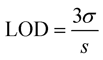
Lentinus polychrous Lèv. mushroom as the natural carbon source was employed for LCDs synthesis due to its high phenolic contents.22 LCDs was green synthesized using hydrothermal method via the condensation reactions of organic molecules, polymerization, and carbonization, respectively.26 Transmission electron microscopic (TEM) images were used to assess the particle size, morphology, and dispersion of the LCDs (Fig. 1). The LCDs were spherical and evenly distributed, in agreement with a previous report.21 From the size distribution, the average size of LCDs was found to be 6.0 nm with a lattice spacing of 0.43 nm (Fig. 1b). The XRD pattern of LCDs shows a diffraction peak at around 20.77°, attributed to (002) graphitic carbon plane (Fig. 1c).27 From the Bragg's law, the interlayer spacing of LCDs was calculated to be 0.43 nm, which is indicative of an amorphous character larger than the lattice graphite (0.34 nm) due to its oxygen-containing functional groups, corresponding to the TEM results.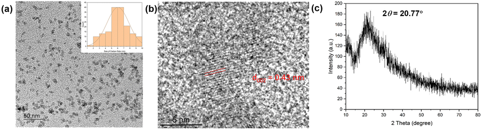 | ||
| Fig. 1 (a) TEM image (inset: size distribution histogram), (b) HRTEM image, and (c) X-ray diffractogram of LCDs. | ||
The surface functional groups and composition of LCDs were elucidated by Fourier transform infrared (FTIR) and X-ray photoelectron spectroscopy (XPS) (Fig. 2). The broad band from 2990 cm−1 to 3660 cm−1 can be attributed to the overlap of –OH/–NH stretching bands, while the peak at 1398 cm−1 is due to O–H bending vibrations. The characteristic peaks at 2890 cm−1 and 1140 cm−1 were assigned to C–H stretching and C–N stretching vibrations, respectively. The strong peak at 1050 cm−1 was assigned to C–O stretching, whereas vibrational absorption peaks at 1668 cm−1 and 1590 cm−1 were arised from C![[double bond, length as m-dash]](https://www.rsc.org/images/entities/char_e001.gif) O and CC functional groups, respectively (Fig. 2a).28–31 Similarities in the FTIR spectra of LCDs and Lentinus polychrous Lév. powder (LLM), the raw materials of LCDs, reveal that the functional groups on the surface of LCDs are inherited from the precursor. Active groups of LLM, such as carboxyl and hydroxyl groups, are abundant, which improves water solubility and also provides more reactivity sites.30,32
O and CC functional groups, respectively (Fig. 2a).28–31 Similarities in the FTIR spectra of LCDs and Lentinus polychrous Lév. powder (LLM), the raw materials of LCDs, reveal that the functional groups on the surface of LCDs are inherited from the precursor. Active groups of LLM, such as carboxyl and hydroxyl groups, are abundant, which improves water solubility and also provides more reactivity sites.30,32
 | ||
| Fig. 2 (a) FTIR spectra of LCDs and LLM, (b) XPS survey spectrum of LCDs, and high-resolution spectra of (c) C1s, (d) N1s, and (e) O1s. | ||
The XPS survey spectrum reveals three peaks at 533.1, 400.1, and 285.1 eV, which correspond to O1s, N1s, and C1s, respectively (Fig. 2b). The LCDs contain 75.84% carbon, 5.11% nitrogen and 19.05% oxygen. The corresponding binding energies indicate the existence of large amounts of carbon and oxygen elements on the surface of the LCDs. The high-resolution XPS spectrum of C1s reveals three peaks at 284.4, 286.1, and 287.7 eV, which correspond to CC/C–C, C–O, and CO groups, respectively (Fig. 2c). The O1s spectrum presents a peak at 531.6 which is assigned to the C–O group (Fig. 2d). The high-resolution spectrum for N1s exhibits two peaks at 399.3 and 401.2 eV, which could be assigned to C–N–C and N–H, respectively (Fig. 2e).29,33,34 These are in line with results from FTIR, which suggests the presence of amine, carboxyl, and hydroxyl groups on the LCDs' surface. Using the Folin–Ciocalteu method, the phenolic content of LCDs was calculated to be 13.65 ± 0.03 mg GAE per g of dry weight, which indicates a high hydroxyl content.
Optical properties of LCDs
The optical features of LCDs were investigated through UV-vis absorption and fluorescence spectroscopy. The appearance of a shoulder at 290 nm can be attributed to π → π* transitions of CC bonds,35 while the shoulder observed at 330 nm can be attributed to n → π* transitions of the CO groups (Fig. 3a).36 Fluorescence emission spectra of LCDs were investigated at excitation wavelengths from 240 to 440 nm. The fluorescence emission spectra of LCDs show the maximum emission wavelengths at 440 nm on excitation at 360 nm (Fig. 3b). The fluorescence emission wavelengths exhibited red shifting as the excitation wavelengths increased (Fig. 3c). This is due to the diverse surface functional groups of LCDs which produce different emissive states, resulting in the excitation-dependent emission.37 The quantum yield (QY) of LCDs showing a strong blue emission was calculated to be 6.4% in an aqueous solution relative to the reference (quinine hemisulfate monohydrate). With a nitrogen content from protein in Lentinus polychrous Lév. mushrooms provide nitrogen-containing functional groups on the surface of LCDs, leading to increasing the fluorescence quantum yield without adding any additional chemicals or functionalization.38
 | ||
| Fig. 3 (a) The UV-vis absorption spectrum, (b) fluorescence emission spectra, (c) normalized fluorescence intensity spectra, and (d) quantum yield of LCDs (1 mg mL−1). Inset (a): a photograph of the LCDs solution under visible light (left) and UV irradiation at 365 nm (right). | ||
The photostability of LCDs was elucidated under UV irradiation and visible light. The relative fluorescence intensity of LCDs exposed to UV light remained approximately 90% of the original level after 2 hours (Fig. 4a), and in the case of visible light exposure remained above 80% after 7 days (Fig. 4b). Furthermore, the fluorescence emission of LCDs with different concentrations of Fe3+ (0–0.6 mM) was investigated in the PBS buffer (pH 7.4) as a mimic of biological fluid (Fig. 4c). The normalized fluorescence intensity of LCDs displayed no change both in deionized water and PBS buffer, indicating that LCDs could be further applied as the fluorescent sensor for sensing Fe3+ in biological system. The effect of high concentrations of sodium chloride (0–2 mM) was also studied (Fig. 4d), and the results indicate that the presence of buffer and salt ions have no significant effect on the fluorescence emission behavior of LCDs.
 | ||
| Fig. 4 Plots of the relative fluorescence intensity (F/F0) of LCDs (1 mg mL−1) under (a) UV light irradiation (365 nm) and (b) visible light, the normalized fluorescence intensity of LCDs (1 mg mL−1) (c) in the presence of Fe3+ (0–0.6 mM) in PBS buffer (pH 7.4), and (d) with the addition of NaCl (0–2 mM). | ||
Fluorescence response of LCDs to Fe3+
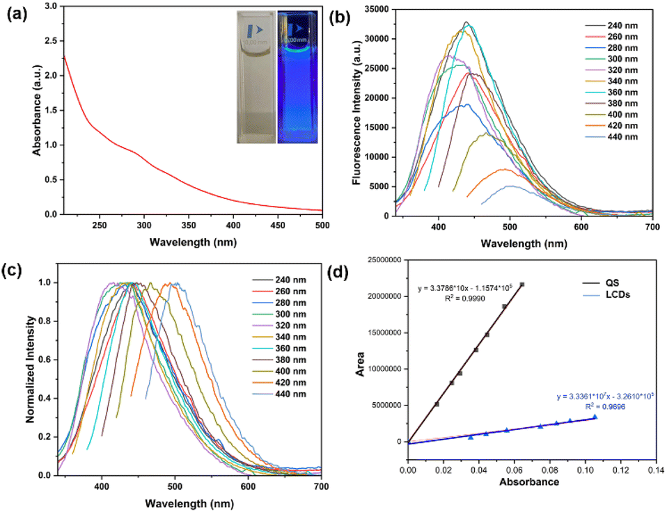
As depicted in Fig. 5a, the fluorescence emission of LCDs is efficiently quenched by Fe3+ ions, and the fluorescence intensity of LCDs exhibits a strong linear relationship in the presence of Fe3+ (0.0 to 2.0 mM). This wide linear range surpasses the reported range in many previous studies.39–44 The limit of detection (LOD) for Fe3+ was estimated to be 16 μM, which exceeds the typical concentration of ferric ions, lower than 0.3 mg L−1 (∼5.4 μM), found in drinking water.45 The LCDs sensor system can thus be effectively employed for detecting ferric ions in natural water sources in the concentrations of 1.0–3.0 mg L−1 (∼18–54 μM), which are considered acceptable for consumption.46 Moreover, it is worth noting that the aquatic life standard for ferric ions is 1.0 mg L−1 (∼18 μM) based on its toxic effects.47 Regardless of Fe3+ concentration, no significant changes in fluorescence emission of LCDs were observed after the addition of Fe3+ (0.1 mM) for 40 minutes (Fig. 5c). To assess the selectivity of LCDs as a detection system, the effect of various ions (Fe3+, Co2+, Cu2+, Cr3+, Pb2+, Mg2+, Ca2+, Fe2+, Zn2+, Hg2+, Br−, NO3−, PO43−, SO32−, and Cl−) on fluorescence behaviour was evaluated (Fig. 5d). Notably, it was observed that Fe3+ induces significant fluorescence quenching of LCDs, whereas the other ions did not. This result suggests that LCDs exhibit high selectivity to Fe3+. Competitive tests in the presence of other potential interference ions, including metal ions and anions, highlight that the selectivity of LCDs for Fe3+ was also maintained. | ||
| Fig. 5 (a) Fluorescence emission spectra of LCDs in the presence of Fe3+ (0–2 mM), (b) linear fluorescence calibration curve of LCDs versus Fe3+ concentration, (c) time-dependent fluorescence response of LCDs in presence of Fe3+ (1.0 mM), and (d) fluorescence intensity of LCDs (1.0 mg mL−1) in the presence of potential interference ions (1 mM) (black bars), and with the same ions at higher concentration (10 mM) and added Fe3+ (1 mM) (red bars). (λex = 360 nm/λem = 440 nm). | ||
To reveal the fluorescence quenching mechanism of LCDs by Fe3+, UV-vis absorption and fluorescence emission spectra were measured. As depicted in Fig. 6a, the UV-vis absorption spectrum of Fe3+ overlaps with both the fluorescence excitation and emission spectra of the LCDs, suggesting that the proposed mechanism of LCDs for Fe3+ binding was the inner filter effect (IFE). The IFE, a nonradiative energy phenomenon, arises from the absorption of excited-emitted light by fluorophores or chromophores present within the system.48,49 The relationship between Fe3+ ion concentration and the relative fluorescence intensity (F/F0) was further studied (Fig. 6b), where F0 and F represent the fluorescence intensities of LCDs in the absence and presence of Fe3+ ions, respectively. The linear relationship occurs in the range of 0–0.8 mM, while this correlation does not extend to higher Fe3+ concentrations (0.8–9 mM), suggesting that the fluorescence quenching mechanism of LCDs for Fe3+ sensing may involve both dynamic and static quenching processes.50 In the dynamic quenching process, the excited fluorescent molecule returns to its ground state due to collision with the quencher.51 The average fluorescence lifetime of the LCDs on excitation at 370 nm was 5.12 ns. In the presence of several Fe3+ concentrations (0.1, 0.5, and 1.0 mM), they were found to be 5.47, 6.65, and 6.75 ns, respectively (Fig. 6c). These results indicate a notable change in the average fluorescence lifetimes of the LCDs, confirming the dynamic fluorescence quenching of LCDs by Fe3+.31 The functional groups in LCDs, such as hydroxyl, amine, and carboxylic acids, are able to coordinate with Fe3+ ions, and accordingly, the static quenching process may involve the formation of a non-fluorescent complex of a quencher and a fluorescent molecule in its ground-state.52 In fact, Fig. 6d shows the aggregation of LCDs in the presence of Fe3+, providing credence to the static fluorescence quenching of LCDs by Fe3+.53 Hence, the quenching mechanism is postulated as being a combination of IFE, dynamic, and static quenching.
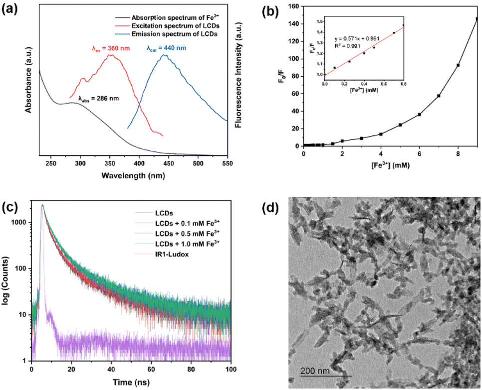 | ||
| Fig. 6 (a) Fluorescence excitation and emission spectra of LCDs and UV-vis absorption of Fe3+ (1.0 mM), (b) the relative fluorescence intensity (F0/F) of LCDs versus Fe3+ concentrations (inset: a linear plot of (F0/F) and Fe3+ concentrations), (c) LCDs fluorescence decay profile in the absence and presence of Fe3+ (monitored at 440 nm), and (d) a transmission electron microscopic image (TEM) of LCDs on addition of Fe3+. | ||
Paper-based LCDs sensor
To examine the selectivity of paper-based LCDs, the RGB values of the paper-based LCDs sensor were measured under identical conditions, including the presence and absence of various ions, including Co2+, Cu2+, Cr3+, Pb2+, Mg2+, Ca2+, Fe2+, Zn2+, Hg2+, Br−, NO3−, PO43−, SO32−, and Cl− (Fig. 7a). Furthermore, the considerable quenching effect was also observed in the presence of the other interference ions (Fig. 7b). Similar to the behavior observed in LCDs solutions, which were highly selective toward Fe3+, the RGB value of the paper-based LCDs sensors was reduced when exposed to Fe3+. For the sensitivity testing, several Fe3+ concentrations (0, 0.2, 0.25, 0.3, 0.4, 0.5, 0.6, 0.7, 0.8, and 1 mM) were dropped on the LCDs coated-filter papers and then observed under a UV irradiation (365 nm), as depicted in Fig. 7c. The blue color of the images darkened as the concentration of Fe3+ was increased, in concert with a reduction in fluorescence intensity. The linear plot between the RGB values extracted from the images and the Fe3+ concentration range (0.2–1.0 mM) displays a well-defined linear response (Fig. 7d). This indicates that the paper-based sensor incorporating LCDs maintained its selectivity and sensitivity towards Fe3+ ions. | ||
| Fig. 7 (a) The plots of RGB values of paper-based LCDs (blank) after the addition of various ions (1 mM), (b) the normalized RGB values under various interferences include Co2+, Cu2+, Cr3+, Pb2+, Mg2+, Ca2+, Fe2+, Zn2+, Hg2+, Br−, NO3−, PO43−, SO32−, and Cl−, (c) images in the presence of Fe3+ (0–1 mM) under UV irradiation (365 nm), and (d) a linear plot of the relative RGB values of paper-based LCDs vs. Fe3+ concentrations (0–1 mM). | ||
Conclusions
This work highlights the synthesis of highly fluorescent Lentinus polychrous Lèv. mushroom-derived carbon dots (LCDs) through a simple one-step hydrothermal method. The resulting LCDs demonstrated blue photoluminescence under UV light. Notably, these LCDs exhibited efficient sensing capabilities for Fe3+ ions, even in the presence of potential interference ions. They displayed good sensitivity with a limit of detection (LOD) of 16 μM in the linear concentration range of 0.0–2.0 mM and sensing was achieved within 40 minutes. Moreover, the LCDs maintained their effectiveness when fabricated as a paper-based sensor. Additionally, their high photostability further indicates the suitability for deployment in diverse environmental conditions. With their sensing properties, environmentally friendly nature, and user-friendly characteristics, these LCDs paper-based sensors hold great promise as a valuable tool for environmental monitoring applications.Conflicts of interest
There are no conflicts to declare.Acknowledgements
The authors acknowledge the support of Kamnoetvidya Science Academy (KVIS). The authors would like to thank technical advice and instrument operation from scientists at the Frontier Research Center (FRC) at Vidyasirimedhi Institute of Science and Technology (VISTEC) and the RMUTT Central Lab, Institute of Research and Development, Rajamangala University of Technology Thanyaburi for facility support. The authors would like to thank Assoc. Prof. Christopher B. Smith and Assoc. Prof. Peerasak Paoprasert for the scientific suggestions, and Dr Taweesak Sudyoadsuk for the fluorescence lifetime suggestion.References
- S. Li, Y. Li, J. Cao, J. Zhu, L. Fan and X. Li, Anal. Chem., 2020, 92, 7988 CrossRef CAS PubMed
.
- G. J. Brewer, Chem. Res. Toxicol., 2010, 23, 319–326 Search PubMed
- T. N. J. I. Edison, R. Atchudan, J.-J. Shim, S. Kalimuthu, B.-C. Ahn and Y. R. Lee, J. Photochem. Photobiol., B, 2016, 158, 235–242 CrossRef CAS PubMed
- S. Lunvongsa, M. Oshima and S. Motomizu, Talanta, 2006, 68, 969–973 CrossRef CAS PubMed
- C. C. Leite, A. de Jesus, M. L. Potes, M. A. Vieira, D. Samios and M. M. Silva, Energy Fuels, 2015, 29, 7358–7363 CrossRef CAS
- J. Lear, D. J. Hare, F. Fryer, P. A. Adlard, D. I. Finkelstein and P. A. Doble, Anal. Chem., 2012, 84, 6707–6714 CrossRef CAS PubMed
- L. Yuan, W. Lin, K. Zheng, L. He and W. Huang, Chem. Soc. Rev., 2013, 42, 622–661 RSC
- X. Wei, H. Li, Z. Li, M. Vuki, Y. Fan, W. Zhong and D. Xu, Anal. Bioanal. Chem., 2012, 402, 1057–1063 CrossRef CAS PubMed
- S. B. Rizvi, S. Ghaderi, M. Keshtgar and A. M. Seifalian, Nano Rev., 2010, 1, 5161 CrossRef PubMed
- G. Ou, J. Zhao, P. Chen, C. Xiong, F. Dong, B. Li and X. Feng, Anal. Bioanal. Chem., 2018, 410, 2485–2498 CrossRef CAS PubMed
- T. S. Atabaev, S. Sayatova, A. Molkenova and I. Taniguchi, Sensing and Bio-Sensing Research, 2019, 22, 100253 CrossRef
- M. Batool, Z. Afzal, H. M. Junaid, A. R. Solangi and A. Hassan, Crit. Rev. Anal. Chem., 2022, 1–28, DOI:10.1080/10408347.2022.2105135
- M. Jorns and D. Pappas, Nanomaterials, 2021, 11, 1448 CrossRef CAS PubMed
- Y. Wang, J. Sun, B. He and M. Feng, Green Chemical Engineering, 2020, 1, 94–108 CrossRef
- J. Fan, L. Kang, X. Cheng, D. Liu and S. Zhang, Nanomaterials, 2022, 12, 4473 CrossRef CAS PubMed
- Y. Xu, Y. Fan, L. Zhang, Q. Wang, H. Fu and Y. She, Spectrochim. Acta, Part A, 2019, 220, 117109 CrossRef CAS PubMed
- X. Ma, Y. Dong, H. Sun and N. Chen, Mater. Today Chem., 2017, 5, 1–10 CrossRef
- S. M. Usman Ali, O. Nur, M. Willander and B. Danielsson, Sens. Actuators, B, 2010, 145, 869–874 CrossRef CAS
- A. Tyagi, K. M. Tripathi, N. Singh, S. Choudhary and R. K. Gupta, RSC Adv., 2016, 6, 72423–72432 RSC
- V. Sharma, P. Tiwari and S. M. Mobin, J. Mater. Chem. B, 2017, 5, 8904–8924 RSC
- M. R. Pacquiao, M. D. G. de Luna, N. Thongsai, S. Kladsomboon and P. Paoprasert, Appl. Surf. Sci., 2018, 453, 192–203 CrossRef CAS
- N. Fangkrathok, J. Junlatat and B. Sripanidkulchai, J. Ethnopharmacol., 2013, 147, 631–637 CrossRef CAS PubMed
- T. Kwamman, T. Chutimasakul, P. Sangangam, N. Puengposop, P. Thangsunan, T. Phonlam and K. Wechakorn, J. Phys. Sci., 2023, 34, 41–57 CrossRef
- C. Seesuea, T. Sangtawesin, P. Thangsunan and K. Wechakorn, J. Fluoresc., 2023 DOI:10.1007/s10895-023-03408-8
- E. Kerr, C. West and S. Kradtap Hartwell, J. Chromatogr. Sci., 2015, 54, 639–646 Search PubMed
- M. L. Liu, B. B. Chen, C. M. Li and C. Z. Huang, Green Chem., 2019, 21, 449–471 RSC
- D. Kumar, K. Singh, V. Verma and H. Bhatti, J. Bionanosci., 2014, 8, 274–279 CrossRef CAS
- A. Dager, T. Uchida, T. Maekawa and M. Tachibana, Sci. Rep., 2019, 9, 14004 CrossRef PubMed
- C. Qi, H. Wang, A. Yang, X. Wang and J. Xu, ACS Omega, 2021, 6, 32904–32916 CrossRef CAS PubMed
- D. Xu, F. Lei, H. Chen, L. Yin, Y. Shi and J. Xie, RSC Adv., 2019, 9, 8290–8299 RSC
- G. Dong, K. Lang, H. Ouyang, W. Zhang, L. Bai, S. Chen, Z. Zhang, Y. Gao, Z. Mu and X. Zhao, RSC Adv., 2020, 10, 33483–33489 RSC
- Y. A. Wang, J. J. Li, H. Chen and X. Peng, J. Am. Chem. Soc., 2002, 124, 2293–2298 CrossRef CAS PubMed
- C. Kang, Y. Huang, H. Yang, X. F. Yan and Z. P. Chen, Nanomaterials, 2020, 10, 2316 CrossRef CAS PubMed
- C. M. Singaravelu, X. Deschanels, C. Rey and J. Causse, ACS Appl. Nano Mater., 2021, 4, 6386–6397 CrossRef CAS
- M. S. Kumar, K. Y. Yasoda, D. Kumaresan, N. K. Kothurkar and S. K. Batabyal, Mater. Res. Express, 2018, 5, 075502 CrossRef
- D. Chang, L. Li, L. Shi and Y. Yang, Analyst, 2020, 145, 8030–8037 RSC
- E. Liu, D. Li, X. Zhou, G. Zhou, H. Xiao, D. Zhou, P. Tian, R. Guo and S. Qu, ACS Sustain. Chem. Eng., 2019, 7, 9301–9308 CrossRef CAS
- N. Fangkrathok, Asian J. Pharm. Sci., 2018, 15, 49–57 Search PubMed
- R. Atchudan, T. N. J. I. Edison, S. Perumal, R. Vinodh, A. K. Sundramoorthy, R. S. Babu and Y. R. Lee, Chemosensors, 2021, 9, 166 CrossRef CAS
- N. Hashemi and M. H. Mousazadeh, Opt. Mater., 2021, 121, 111515 CrossRef CAS
- W. U. Khan, D. Wang, W. Zhang, Z. Tang, X. Ma, X. Ding, S. Du and Y. Wang, Sci. Rep., 2017, 7, 14866 CrossRef PubMed
- Y. Zhao, X. Zhu, L. Liu, Z. Duan, Y. Liu, W. Zhang, J. Cui, Y. Rong and C. Dong, Nanomaterials, 2022, 12, 2377 CrossRef CAS PubMed
- S. Pang and S. Liu, Anal. Chim. Acta, 2020, 1105, 155–161 CrossRef CAS PubMed
- J. Deng, J. Hu, J. Zhao, N. An, K. Liang, Q. Wang, Z. Zhang, R. Wu and F. Zhang, Arabian J. Chem., 2021, 14, 103195 CrossRef CAS
- N. Khatri, S. Tyagi and D. Rawtani, Journal of Water Process Engineering, 2017, 19, 291–304 CrossRef
- Water, Sanitation, Hygiene and Health, World Health Organization, 1998 Search PubMed.
- M. Kumar and A. Puri, Indian Journal of Occupational and Environmental Medicine, 2012, 16, 40–44 CrossRef PubMed
- L. Bu, J. Peng, H. Peng, S. Liu, H. Xiao, D. Liu, Z. Pan, Y. Chen, F. Chen and Y. He, RSC Adv., 2016, 6, 95469–95475 RSC
- H. Shabbir, E. Csapó and M. Wojnicki, Inorganics, 2023, 11, 262 CrossRef CAS
- S. Liu, R. Liu, X. Xing, C. Yang, Y. Xu and D. Wu, RSC Adv., 2016, 6, 31884–31888 RSC
- D. Genovese, M. Cingolani, E. Rampazzo, L. Prodi and N. Zaccheroni, Chem. Soc. Rev., 2021, 50, 8414–8427 RSC
- M. J. Molaei, Anal. Methods, 2020, 12, 1266–1287 RSC
- M. Picard, S. Thakur, M. Misra and A. K. Mohanty, RSC Adv., 2019, 9, 8628–8637 RSC
| This journal is © The Royal Society of Chemistry 2023 |