 Open Access Article
Sustainable hydrogen generation and storage – a review
Mrinmoy Kumar Sarmaha,
Tej Pratap Singh b,
Pankaj Kalita
 *c and
Anupam Dewan
 d
d
aSchool of Energy Science and Engineering, Indian Institute of Technology, Guwahati, India. E-mail: s.mrinmoy@iitg.ac.in
bDepartment of Applied Mechanics, Indian Institute of Technology, Delhi, India. E-mail: tej5050@gmail.com
cSchool of Energy Science and Engineering, Indian Institute of Technology, Guwahati, India. E-mail: pankajk@iitg.ac.in
dDepartment of Applied Mechanics, Indian Institute of Technology, Delhi, India. E-mail: adewan@am.iitd.ac.in
First published on 23rd August 2023
Abstract
In 21st century, the energy demand has grown incredibly due to globalization, human population explosion and growing megacities. This energy demand is being mostly fulfilled by fossil-based sources, which are non-renewable and a major cause of global warming. Energy from these fossil-based sources is cheaper, however challenges exist in terms of climate change. This makes renewable energy sources more promising and viable for the future. Hydrogen is a promising renewable energy carrier for fulfilling the increasing energy demand due to its high energy density, non-toxic and environment friendly characteristics. It is a non-toxic energy carrier as combustion of hydrogen produces water as the byproduct whereas other conventional fuels produce harmful gases and carcinogens. Because of its lighter weight, hydrogen leaks are also easily dispersed in the atmosphere. Hydrogen is one of the most abundant elements on Earth, yet it is not readily available in nature like other fossil fuels. Hence, it is a secondary energy source and hydrogen needs to be produced from water or biomass-based feedstock for it to be considered renewable and sustainable. This paper reviews the renewable hydrogen generation pathways such as water splitting, thermochemical conversion of biomass and biological conversion technologies. Purification and storage technologies of hydrogen is also discussed. The paper also discusses the hydrogen economy and future prospects from an Indian context. Hydrogen purification is necessary because of high purity requirements in particular applications like space, fuel cells etc. Various applications of hydrogen are also addressed and a cost comparison of various hydrogen generation technologies is also analyzed. In conclusion, this study can assist researchers in getting a better grasp of various renewable hydrogen generation pathways, it's purification and storage technologies along with applications of hydrogen in understanding the hydrogen economy and its future prospect.
1. Introduction
Globalization and modernization in the 21st century are based on energy consumption and the majority of the world's energy demand is met by the utilization of fossil fuel-based resources. This continuous and systematic usage has led to dwindling fossil-based resources, and the focus of researchers has shifted towards alternate sources of energy.1 Additionally, escalating prices and serious impacts on the environment due to extensive burning of fossil fuels has shifted the world's focus towards clean and renewable energies.2 This increasing and significant need for developing a renewable and clean energy source owing to greenhouse effects and environmental pollution has aroused interest in hydrogen (H2) as a fuel because of its high calorific value.3Hydrogen is not readily accessible in nature unlike other fuels derived from fossil-based resources and hence it is a secondary energy source which can be produced from different primary sources of energy. It can be produced by fossil fuel gasification (natural gas and coal), water splitting by photolysis, water electrolysis, and thermochemical and biological biomass conversion.4 Hydrogen can be utilized in fuel cells for producing electricity and in internal combustion engines for direct combustion.5
Hydrogen is a clean, non-toxic, and emission-free fuel with an energy yield of 122 kJ g−1 i.e., approximately 2.75 times higher than most hydrocarbon fuels.7 Fig. 1 shows the energy content comparison of different fuels (drawn using data from ref. 6). The renewable energy policies throughout the world are centered on the application of hydrogen as a fuel in combustion engines and electric vehicles by the use of fuel cells. Implementation of hydrogen as a fuel in transportation systems is free of toxic gas and CO2 emission and the byproduct is only water vapour.8 Different industries, such as, chemical, petroleum and food processing plants utilize hydrogen as feedstock in huge amounts. It is also utilized for hydro-treating, desulfurization and chemical manufacturing.9 Despite its unique characteristics, such as, eco-friendly nature, efficient energy carrier and high calorific value, there are some practical limitations of hydrogen, such as, obtaining higher percentage of purity and storage. Due to a low density of hydrogen 0.082 kg m−3 at STP and high inflammability, its storage possess challenges.10
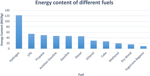 | ||
| Fig. 1 Energy content of different fuels (drawn using data from ref. 6). | ||
Some challenges are encountered during the usage of renewable energy sources for the production of hydrogen. Specific ambient conditions, such as, solar irradiation in the case of solar energy and wind speed for wind energy vary the output of energy produced from these renewable resources. In the case of biomass, the need for the availability of a required amount of biomass at a particular place hampers the energy production from this resource. Such dependence and intermittent nature of renewable resources fluctuate the production of hydrogen.11
An energy storage system is required for utilizing the true potential of renewable energy sources.12 Numerous technologies are available to store hydrogen. The commercial and most common method for hydrogen storage is in high pressure cylinders by compression.13 The volume requirement of cylinders for such hydrogen storage is large as hydrogen has lower density than that of other fuels.14 Other ways in which hydrogen can be stored are metal hydrides and in cryogenic form ref. 15.
The present review article discusses different reported renewable technologies for hydrogen production. It also discusses the purification technologies, storage systems, and presents a brief discussion on the applications of hydrogen and its cost analysis. It provides important details that can be used for design and development of different technologies for hydrogen production, its purification and storage. This review will be helpful in academic research concerning hydrogen and hydrogen economy.
2. Hydrogen economy and future prospects for India
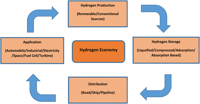
The concept of a hydrogen economy means that hydrogen will be produced from various renewable sources in large quantities, and it would be used to substitute fossil-based fuels in transportation, residential, commercial and industrial sectors. Developing a successful hydrogen economy will mean advantageous for the energy security of a country, its economy and environment, and finally the consumers.16 Although hydrogen is quite scarcely available in its free state, it is abundantly available in the environment in the form of hydrocarbons and water, etc. Because of this scarce availability in free state, we need to first produce hydrogen from various sources, then store (in metal hydrides, cryogenic form or compressed form), and transport it for end-user applications.14 Fig. 2 presents a schematic of a hydrogen economy.Given India's current progress in the renewable energy sector, it is evident that hydrogen derived from renewable resources will have a significant impact on the country's overall energy sector. In the Indian transportation sector, green hydrogen will be the key in providing sustainable solution. The demand for hydrogen will augment from the present 6 Mt to 28 Mt by the year 2050 and the hydrogen generation cost from renewable sources will decline around 50% by the year 2030 as predicted by The Energy and Research Institute (TERI) of India. The institute claims, approximately 80% of hydrogen will be generated using renewable sources in India by the year 2050.17 Fossil fuels provide flexibility to the end user in various applications, which at the time cannot be provided by renewable sources. Nonetheless, hydrogen generation integrated with renewable sources can provide the required flexibility. Hydrogen can become a feasible option in meeting the carbon neutrality targets set by 2015 Paris agreement which targets to restrict global warming below 2 °C. With above-mentioned numerous advantages, hydrogen is considered by researchers as a prospective player to meet energy demands while addressing air pollution challenges and increasing energy security.
Numerous public and governmental institutions in India are making investments in development and research of technology in the field of hydrogen, notably in developing new systems, processes, materials etc. Indian institutions such as Tata Motors, Bharat Heavy Electricals Limited (BHEL), Indian Oil Corporation (IOCL) and Indian Space Research Organization (ISRO) are diligently working in technologies based on fuel cell and hydrogen. This continuous exploration will help India in facing several challenges concerning standards formulations, regulations, fuel cell technology acceptance etc. India is one of the participants in Mission Innovation (MI). It is working on innovation challenges put forth by the mission, which are focused on clean and renewable hydrogen.18
3. Renewable hydrogen generation pathways
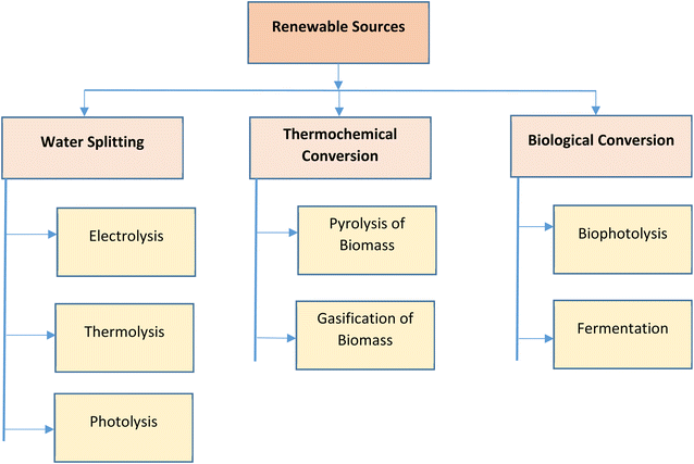
In the past few years, the expenses related to renewable energy has witnessed considerable drop due to uncertainty and variations in oil and natural gas prices in international markets.19 Hydrogen is produced from various energy sources, such as, fossil-based or renewable sources. Various techniques, such as, coal gasification, biomass gasification, steam reforming, biomass pyrolysis, electrolysis of water, etc., are utilized for the extraction of hydrogen. On a commercial scale, hydrogen is majorly produced by steam reforming, which also emits CO2. In recent times, researchers and governments of most countries have put more effort towards developing environmental friendly renewable sources for hydrogen generation. This growth in renewable energy sources has led to the design of additional efficient fuel production systems. In this review, emphasis has been given to the techniques of hydrogen generation using renewable resources, such as, water splitting, thermochemical conversion of biomass and biological conversion of biomass.20 The various renewable hydrogen generation pathways are represented in Fig. 3.3.1. Hydrogen from water splitting
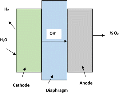
Water consists of hydrogen and oxygen and this makes it the most abundant source for hydrogen generation. Electrical, thermal and photonic energy is used for hydrogen production by splitting of water.21 Hydrogen generation from water can be categorized into three major types, namely, hydrogen from water using electricity (electrolysis),22 using photons (photolysis)23 and using thermal energy (thermolysis).21Alkaline electrolysis is a mature form of technology. The electrolyzers which are being used in alkaline electrolysis are commercially available in MW scales.27 The temperature during the process ranges from 60 °C to 80 °C. The process utilizes NaOH or KOH as electrolytes and nickel is used in electrodes. The electrolyte concentration can vary from 20% to 30%. A diaphragm made of asbestos is used to separate the two electrodes.28 The efficiency of alkaline electrolysis process is approximately 50–60% and the hydrogen produced has a purity of 99.5–99.9%.28 The reactions taking place in cathode and anode of alkaline electrolysis are as follows-
| Reaction at anode: 2OH− → H2O + ½O2 + 2e− |
| Reaction at cathode: 2H2O + 2e− → H2 + 2OH− |
| Net reaction of cell: H2O → H2 + ½O2 |
The schematic diagram of the alkaline electrolysis process is depicted in the Fig. 4.29,30 Anion exchange membrane is a new step towards alkaline electrolysis process of water splitting. The membranes are made up of polymers in place of asbestos.31,32
Solid oxide electrolysis is being researched on laboratory scales and is a relatively new technology. The operating temperature ranges from 700–900 °C and a solid ion-conducting ceramic is utilized as electrolyte.33 The efficiency of solid oxide electrolysis is in the range of 85–90% at higher temperatures. This is due to improvement in reaction kinetics34 and higher thermodynamic efficiency.35
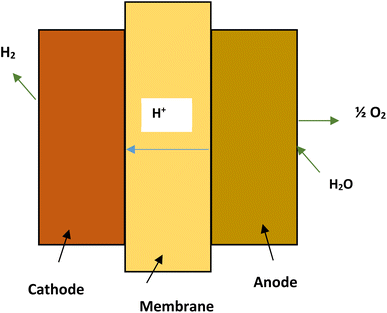
The PEM electrolyzers in proton exchange membrane electrolysis (Fig. 5) use iridium and platinum black electrode catalyst. The membrane separating the electrodes is made of Nafion. The process is limited to a maximum temperature of 80 °C.27 High water purity, system complexity and costs are major drawbacks of proton exchange membrane electrolysis.33 The reactions taking place in the anode and cathode of PEM cell may be written as:22
| Reaction at anode: H2O → 2H+ + ½O2 + 2e− |
| Reaction at cathode: 2H+ + 2e− → H2 |
| Net reaction of cell: 2H2O → H2 + ½O2 |
Let us consider we have 150 kg water and we use the water electrolysis process to produce hydrogen. The molar masses of water (H2O) and hydrogen (H2) are 18.015 and 2.016. According to the reaction H2O → H2 + ½O2, we have 0.1119 kgH2/kgH2O. Hence, for 150 kg water, total mass of hydrogen produced using water electrolysis process = (150 kg) × (0.1119 kgH2/kgH2O) = 16.785 kgH2.
Using renewable energy sources, such as sunshine, PEC water splitting is a useful method for creating hydrogen fuel. A semiconductor substance that serves as a photocatalyst is often used in the process. In the presence of sunshine, this semiconductor material absorbs photons and produces electron–hole pairs. The water-splitting reaction is then fueled by the excited electrons and holes participating in redox reactions.
According to PEC water splitting, the general reaction for producing hydrogen from water (see Fig. 6) is as follows:36
| Energy (sunlight) + 2H2O(l) → 2H2(g) + O2(g) |
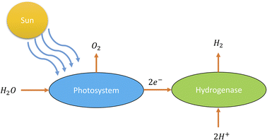 | ||
| Fig. 6 Schematic diagram of photolysis.36 | ||
The energy from sunlight is used in this reaction to split water (H2O) into hydrogen gas (H2) and oxygen gas (O2). This process is greatly aided by the photocatalyst, which is frequently a semiconductor substance like titanium dioxide (TiO2) or other metal oxides. As a result of the photocatalyst absorbing light energy, the photolysis component of this process causes water molecules to disintegrate into their component hydrogen and oxygen atoms. In semiconductors, electrons are excited and form electron–hole pairs when photons with a high enough energy strike the semiconductor surface. The excited electrons can reduce protons (H+) at the semiconductor's surface to generate hydrogen gas, and the holes in the semiconductor's valence band serve as electron acceptors.
The main benefit of using photolysis for hydrogen creation is that it makes use of free, abundant, and renewable solar energy, making it a sustainable and green way to make hydrogen fuel. To make this method more economically viable and scalable for large-scale hydrogen production from water, it is necessary to address some issues, such as enhancing the effectiveness of the photocatalysts and guaranteeing stability and longevity in practical settings. To increase the effectiveness and utility of this process, scientists are still investigating and developing new photocatalysts and engineering methods.
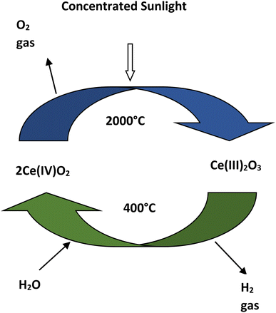
| Reduction: 2Ce(IV)O2 → Ce(III)2O3 + ½O2 |
| Oxidation: Ce(III)2O3 + H2O → 2Ce(IV)O2 + H2 |
| Net reaction: H2O → ½O2 + H2 |
The advantages of thermolysis process is that it has a higher working temperature range of 400–2000 °C and for separating oxygen-hydrogen, membrane is not required.38,39 In this process hydrogen can be produced by the decomposition of water in a single step but it requires temperature higher than 2000 °C.38 Due to the higher temperature requirement in single step decomposition, two or multi step thermolysis process is proposed for hydrogen production using water splitting.40
3.2. Hydrogen from thermochemical conversion of biomass
Pyrolysis and gasification technologies are types of thermochemical conversion of biomass that are utilized to produce hydrogen. In this approach chemical conversion of biomass at elevated temperatures produces hydrogen and hydrogen rich gas mixtures.41Biomass gasification can be defined as the thermochemical conversion of carbonaceous biomass into gaseous fuel. The process begins with biomass being heated to produce a gas which primarily consists of H2, CO2, CO, H2O vapours, CH4 and N2. Char particles, tar and ash are some contaminants which are found in gaseous fuel. The process of gasification occurs in a special type of reactor called a gasifier. The gasification process is a partial oxidation process which occurs at elevated temperature and pressure inside a gasifier. In gasifier, a gasifying agent is inserted which comes in contact with the biomass feed. A series of chemical reactions occur within the gasifier which convert the biomass feed into syngas and ash. The heat released during the partial oxidation process is used for the gasification reactions. Air, steam, oxygen or a combination of these in limited supply serve as the gasifying agent. The process of gasification with oxygen as the gasifying agent is not economical and therefore more attention is being given to steam as a gasifying agent as it produces syngas with a higher percentage of hydrogen. It is also capable of removing contaminants, such as, char and tar through steam reformation.51
The effect of using different gasification agents has been observed in various reported studies which affect the hydrogen concentration and also its yield during the biomass gasification. For example, Song et al.52 in their review found that the concentration of hydrogen ranged 5–25% in response to air gasification while the range of hydrogen concentration varied 20–60% with steam gasification. The yield of hydrogen ranged 0–20 ml g−1 for air gasification and it ranged 200–1400 ml g−1 for steam gasification. It can be observed that the utilization of steam gasification provides syngas with a higher hydrogen concentration and yield. Air is selected as a gasifying agent due to its lower costs, but the heating value of syngas is low (4–7 MJ Nm−3) due to higher concentration of nitrogen in air. The use of oxygen as the gasifying agent helps to increase the heating value of syngas in the range 12–28 MJ Nm−3., but as oxygen is expensive it is used less frequently. Steam is mostly preferred as the gasifying agent to produce hydrogen as it gives a suitable heating value of the obtained syngas in the range 10–18 MJ Nm−3.53 Guan et al.54 reported that the optimal steam-to-biomass ratio (S/B) was 0.6–0.9 for higher hydrogen production in biomass gasification.
Biomass gasification depends on other gasification parameters, such as, temperature inside the gasifier, the biomass feedstock used and also the equivalence ratio (ER). Boudard reaction, steam reformation reaction and water-gas shift reaction are endothermic reactions that take place in biomass gasification and higher temperatures favour the product of endothermic reactions. Li et al.55 observed that with increasing temperature gradient, hydrogen concentration first increased and then decreased before levelling out. Maximum hydrogen concentration was observed at temperature of 917 °C. At 1300 °C tar concentration decreased to less than 0.2 g Nm3 as reported by Briesemeister et al.56 Al-Zareer et al.57 reported that three constituents of biomass, fixed carbon content, ash content and volatile matter, had a positive effect on hydrogen concentration in syngas. The way the temperature influences the syngas characteristics is depicted in Fig. 8.
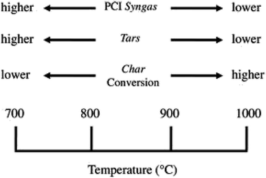 | ||
| Fig. 8 [Fig. 2 influence of temperature process on the syngas characteristics.] Adapted from Molino, A., Chianese, S., & Musmarra, D., Biomass gasification technology: the state of the art overview. Journal of Energy Chemistry, 2016, 25(1), 10–25, DOI: 10.1055/s-0035-1560215. | ||
The chemical reactions taking place in the gasification process within the gasifier may be written as:58
Oxidation reaction
| C + O2 = CO2 + 393.8 MJ kmol−1 |
| H2 + ½O2 = H2O + 242 MJ kmol−1 |
Boudouard reaction
| CO2 + C = 2CO − 172.6 MJ kmol−1 |
Steam reaction:
| C + H2O = CO + H2 − 131.4 MJ kmol−1 |
Water–Shift reaction:
| CO2 + H2 = CO + H2O + 41.2 MJ kmol−1 |
Methanation:
| C + 2H2 = CH4 + 75 MJ kmol−1 |
Other reactions:
| C + CO2 = 2CO |
| CH4 + H2O = CO + 3H2 |
The gasification process is carried out in a reactor termed as a gasifier. Biomass gasifiers have been developed into different types. The differentiation is made based on the direction of flow of biomass feed and the gasifying agent, the way biomass feed is supported on the reactor vessel and how heat is being supplied to the reactor. Table 1 compares various biomass gasifiers in terms of features, advantages and disadvantages.55–60
| Gasifier | Features | Advantages | Disadvantages |
|---|---|---|---|
| Updraft | • Counter current flow leads to effective heat transfer | • Thermal efficiency is high | • High tar content |
| • Biomass feed with high moisture content can be used | • Carbon conversion rate is high | • High ash content | |
| • Feed of various sizes can be used | • Gasifier construction is simple | • Tar cracking required | |
| Downdraft | • Ash and dust entrainment is limited | • Carbon conversion is high | • Pre-treatment of biomass feed is required |
| • Low tar content | • Difficulty in starting and temperature control | ||
| • Clean gas production | • Heat transfer coefficient is low | ||
| • Syngas calorific value is high | |||
| • Low cost | |||
| Bubbling fluidized bed | • Load and process flexibility is good | • Reaction rate is high | • High ash content |
| • Biomass feed and gasifying agent mixing is good | • Carbon conversion is high | • Biomass feed size limitation | |
| • Materials with different properties can be used | • Higher ability for scale-up | • Heterogeneous materials require pre-treatment | |
| Circulating fluidized bed | • Fuel flexibility is high | • Low tar content | • Fine pulverized biomass feed is required (<100 mm) |
| • Carbon conversion is high due to particle re-circulation | • Complex technology | ||
| • Higher ability to scale-up | • Start-up cost and investment cost is high | ||
| Entrained flow | • Uniform temperature can be maintained in gasifier | • High fuel flexibility | • Cold gas efficiency is low |
| • Feed residence time is short inside gasifier | • Tar content is quite low | • Cost of plant set-up and maintenance is high | |
| • Carbon conversion is high | • Requirement of oxidant is large | ||
| • System components have a short life |
3.3. Hydrogen from biological conversion
The hydrogen production technologies based on biological conversion are considered to be environment friendly and sustainable for the future generation.61–67 These biological conversion processes are carbon neutral and renewable. The present work discusses biophotolysis and fermentation technologies involved in biological hydrogen production.The biophotolysis process is classified into indirect and direct biophotolysis. The following biochemical reactions occur during indirect biophotololysis conversion:
| 12H2O + 6CO2 + light → C6H12O6 + 6O2 |
| C6H12O6 + 12H2O → 12H2 + 6CO2 |
| 12H2O + light → 12H2 + 6O2 (overall reaction) |
Microorganisms like microalgae directly produces hydrogen from water through direct biophotolysis process. The following biochemical reaction occurs during the process:
| 2H2O + solar energy → 2H2 + O2 |
It can be observed from the above biochemical conversion reactions taking place during indirect and direct biophotlysis that molecular H2 and O2 are the only products of the process. CO2 gets absorbed by the microorganisms during the biochemical reactions which makes the biophotolysis process carbon neutral. Microalgae and cyanobacteria have received the highest attention among the microorganisms by the researchers which are capable of producing hydrogen by biological conversion.69 The biophotolysis process is confirmed in the laboratory scale and it requires extensive research before commercialization.
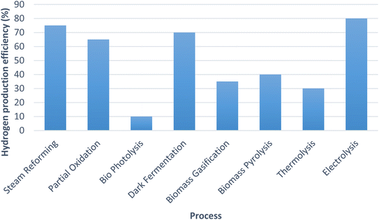
The graph shown (Fig. 9) below compares the hydrogen production efficiencies of various processes which are being used for hydrogen generation worldwide.22,28,73,74
4. Advanced gasification technologies for hydrogen production
To increase and enhance hydrogen yield and concentration, different advanced gasification technologies have been developed and studied. Studies based on these technologies have been conducted to reduce carbon emissions as much as possible. We discuss here steam gasification, supercritical water gasification, multi-stage gasification, chemical looping gasification and solar driven gasification.4.1. Steam gasification
Steam gasification is a thermochemical conversion process of biomass for hydrogen generation. It is believed to produce hydrogen without making a carbon footprint in the environment.75 Hydrogen generated has a higher yield than that by other thermochemical conversion processes, such as, fast pyrolysis, air gasification, oxygen gasification and char steam reforming. The introduction of steam as gasifying agent initiates a more water-gas shift reaction which leads to lesser tar formation and higher hydrogen yield. Biomass with moisture content less than 35% is more suitable for steam gasification.76 Steam gasification has a few advantages; it is an effective process for renewable hydrogen generation with minimal impact on the environment.Florin et al.77 performed steam gasification of biomass with Calcium oxide (CaO), which acts as sorbent and helps in CO2 capture. Without CO2 capture the experimental H2 concentration observed ranged 40–50% volume but with the introduction of CaO as sorbent and CO2 capture the H2 concentration was observed to increase 40–80% volume (dry). Jeong et al.78 carried out steam gasification of polythene using a two-stage gasifier and active carbon. Hydrogen concentration from steam gasification with active carbon was observed in range 60–65% volume, which was the highest ever reported. Table 2 shows the hydrogen yields reported by various researchers while varying the S/B (steam to biomass) ratio.
4.2. Supercritical water gasification
A hydrothermal technology called supercritical water gasification (SWG) is used to transform biomass to a hydrogen rich yield of syngas at elevated temperatures and pressures.85–88 Water in a supercritical state exists when its temperature and pressure are above the critical point (temperature >374 °C and pressure >22 MPa). In this state water has no distinct gaseous and liquid phases i.e., the properties of both gas and liquid phases become identical. In a supercritical state, the surface tension is non-existent as the gas and liquid phase boundary is not relevant. Water above its supercritical state exhibits good solvation properties and improved mass temperature. The high diffusivity and viscosity of supercritical water gasification enhances different reaction rates and contributes to a higher yield of hydrogen in syngas. The various product concentrations of syngas produced by supercritical water gasification depend on process parameters, such as, pressure, temperature, residence time, biomass particle size, feed concentration, presence of catalyst and gasifier configurations. Biomass with high moisture content (>50%) can be directly gasified without drying using a supercritical water gasification process.894.3. Multi-stage gasification
Multiple-stage gasification or staged gasification is a thermochemical conversion gasification process which is carried out in multiple interconnected systems. In this gasification pyrolysis of biomass and gasification is carried out in separate areas within the gasifier. This feature allows the conversion of biomass to syngas to be optimized in steps. The most important reason for the development of staged gasification is to produce syngas with low tar concentration and higher hydrogen yield. Here, the volatile matter present in biomass is released at lower temperatures and then it gets gasified at a higher temperature. Biochar obtained from pyrolysis can be used as a catalyst and heat carrier for enhancing tar cracking and as a result, the overall process efficiency and product yield and quality can be increased in comparison to single-stage gasification.90Recently several multi-staged gasification processes have been developed for conducting biomass pyrolysis and gasification in separate zones in a gasifier. For example, the FLETGAS process was developed at University of Sevilla91 and the 75 kW Viking gasifier was developed at Danish Technical University.92 In another process, a three-stage gasification process for biomass was developed for hydrogen production from biomass. In the first stage the biomass pyrolysis was carried out in a fluidized bed gasifier, in the next stage char was gasified in an entrained bed and in the final stage syngas was produced in a fixed bed gasifier using catalytic steam reform. It was observed that the conversion rate of biomass increased from 78.84% to 92.06% and the hydrogen yield increased from 534.35 to 875.73 ml g−1.93
4.4. Chemical looping gasification
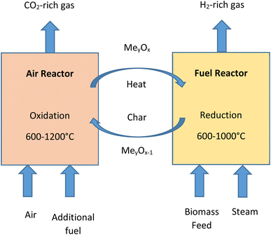
Chemical-looping gasification emerged as a novel gasification process used for the conversion of biomass into gaseous products. The technology has various proven advantages, such as, higher quality of syngas being produced, higher hydrogen yield and lesser impact on the environment.94,95 In the process of chemical-looping gasification the inorganic compounds present in biomass act as effective catalysts and enhance the reactions taking place.52,78 The process is developed to avoid direct contact between fuel and air in reactors. This is accomplished by the circulation of metal/metal oxides which work as oxygen carriers between the reactors. The system of chemical-looping technology consists of two reactors, i.e., fuel reactor (FR) and air reactor (AR).96 In the fuel reactor, biomass undergoes partial oxidation in the presence of metal oxides (MexOy) to produce gases, such as, H2, CO2 and CO. Steam may be added as a gasifying agent in fuel reactor char gasification and reforming reactions. Fig. 10 shows a simple biomass chemical-looping gasification process. The process is capable of decomposing combustion and gasification reaction products by the circulation of the process and thus it helps in situ CO2 separation and makes the process carbon negative.974.5. Solar-driven gasification
In the solar-driven gasification process, solar heating is combined with biomass gasification. The advantage of combining these two processes is that it reduces the energy input, minimizes CO2 production, the energy conversion efficiency is improved and syngas calorific value is increased. In many gasification processes, at times high-temperature heat source is required to promote reactions but by application of solar-driven gasification, this requirement is resolved. Weldeikidan et al.98 reported 35–50% recovery of solar energy during the gasification process.The reactors used in the solar gasification may be classified as directly irradiated and indirectly irradiated reactors. The solid carbonaceous contents in biomass gets directly exposed to solar irradiation in the case of directly irradiated reactors while in the case of indirectly irradiated reactors, the heat from solar radiation is transferred by the use of an opaque wall to the reactor.99 Bellouard et al.100 utilized a solar parabolic condenser for heating wood in temperature range 1100–1300 °C and recorded the rate of carbon conversion to be more than 94%. The yield of the gas exceeded 1568 ml g−1 and there was an increase in biomass energy up to 1.21 times. Wu et al.95 utilized a tracking condenser for obtaining supercritical fluid (500−650 °C). This utilization helped to drive supercritical water gasification.
5. Hydrogen purification
A majority of industrial applications require pure H2 to be used and applied in various processes. Moreover, H2 produced from various sources while being applied to fuel cells needs to satisfy the concentrations determined by the International Organization for Standardization (ISO). Different techniques are used for hydrogen purification such as, cryogenic separation, pressure swing adsorption and membrane-based separation.101 Table 3 shows H2 recovery and purity for different purification technologies.5.1. Membrane separation
The membrane separation technology for hydrogen separation works on the basic principle of selective permeability of particular substances through the membrane. This technology has some advantages, such as, it can be planned in a compact structure, it is flexible in operation depending on the situation and the energy consumption is small.106 These inherent advantages of membrane-based separation have drawn considerable attention of researchers.A selectively permeable membrane is utilized in the membrane separation process. This membrane achieves purification and separation by selectively permeating the gaseous feed through it. The pressure difference, potential difference and concentration difference are the driving forces due to which this selective permeation takes place in the membrane.107 Hydrogen purity of 99.99% or even higher can be achieved by this technology but material selection for the membrane plays a quite important role. The commonly used membrane materials are mainly polymer-based, metal-based, and carbon-based and a new type of metal–organic framework (MOF) has been applied to improve the membrane performance.108 Inside the membrane, the molecules of hydrogen split into electrons and protons on a metal film. The metal film allows the protons to pass through where it combines with electrons on the other side and thus hydrogen regenerates. Gases, such as, CO2, CH4, O2 and N2 are stopped to selectively permeate hydrogen. The most commonly used membrane material is palladium (Pd) since it provides excellent permeability of hydrogen and its higher resistance to decomposition by hydrogen.109
5.2. Pressure swing adsorption
Since the 1950s, the method of adsorption has been in use for the purification and separation of gas on an industrial scale due to high economic performance of this method. Typically, the method consists of two steps adsorption and desorption. The feasibility is determined by the capacity of the adsorbent to remove the undesirable gas in the adsorption step and in the desorption step, the economic viability of the pressure swing adsorption method can be decided.110 Pressure swing adsorption (PSA) is utilized to regenerate the adsorbent and due to fast regeneration capability, it is considered more viable.111 The selection of proper adsorbent and its configuration is critical for an efficient removal of impure gases and obtaining higher purity products. The application of pressure swing adsorption for hydrogen purification depends on the selection of adsorbent and the employed process parameters.112 In addition, for adsorbent selection, it is needed to properly optimize the pressure swing adsorption (PSA) process for a higher efficiency of purification of the product.The commonly used adsorbents in PSA for gas purification are zeolite, activated alumina, molecular sieves, silica gel and activated carbon. Numerous studies have been performed and their outcomes show an improvement in impurity removal through improvements and modifications of these adsorbents. For example, palm shell charcoal, hollow fibres, hydroxyl aluminium silicate, dip-coated Ni foam network, UTSA-16 and MOF have been reported in several studies to have higher adsorption rates and higher selective adsorption performance. In PSA multiple beds are used for hydrogen purification. However, the basic system consists of two adsorption beds. It was established and verified in a study by conducting a theoretical model that the process efficiency improved with an increasing number of adsorption beds.113
5.3. Cryogenic separation
Cryogenic separation is the technique of H2 purification which makes use of condensation properties of materials in accordance with temperature. The principle of separation is quite simple and it uses the difference in volatility of various components in the stream. In the stream of syngas among all the gases and hydrocarbons, H2 has higher volatility. Due to this high volatility of H2, the temperature of the syngas stream is decreased to condense hydrocarbons and other gases. Cryogenic separation is mostly utilized for H2 and hydrocarbon separation. This method is proven for recovery of high H2 yield, but the prior separation of CO2 and other gases is required before feeding the gas to avoid equipment clogging at lower temperatures. The downside of this is the high energy consumption needed in gas cooling and compressor equipment during the actual operation.114 This results in increased costs to be dealt with in the cryogenic separation process.6. Hydrogen storage
The technique of securely and efficiently storing hydrogen gas for eventual use as an energy source is known as hydrogen storage. Because of its high gravimetric energy density and the ability to be utilized in fuel cells or combustion engines, hydrogen is seen as a prospective replacement for traditional fossil fuels. Due to its low weight and high volatility, hydrogen must be stored carefully to ensure its safe and efficient handling. Hydrogen storage has been accomplished using a variety of techniques and technologies, each with advantages and restrictions. Some of the hydrogen storage techniques are underground hydrogen storage, metal hydride storage, compressed gas storage and liquid hydrogen storage.Increasing the use of hydrogen as a sustainable energy source requires the development of efficient and affordable hydrogen storage devices. In order to fulfill different needs of many applications, ranging from transportation to stationary power generation, ongoing research and development activities are aimed at enhancing the energy density, safety, and viability of various hydrogen storage techniques.
6.1. In metal hydride form
In the late 1960s and early 1970s, there was a resurgence of interest in metal hydrides as a way to store hydrogen. This was due to the fuel crisis and the need to develop a hydrogen-based transportation system. Since then, different types of metal hydrides have been created and studied. In metal hydride storage, hydrogen breaks into atoms at the metal surface, enters the metallic lattice as atoms, diffuses through the metal, jumps between interstitial sites, and forms a hydride phase with a more or less organized hydrogen sub-lattice. The hydrogen s electron can be partially given to the conduction band if the (inter) metallic lattice has d or f electron states at the Fermi surface. In addition, the proton can move across the lattice easily because it is electrostatically filtered by the electrons at the Fermi surface.115–117 The most well-known are AB5-type hydrides (LaNi5 is a good example) and AB2-type hydrides.118,119 Certain metals and alloys react with hydrogen to generate metal hydrides, which results in the solid-state storage of hydrogen at moderate temperatures and pressure, giving them a significant safety advantage compared to the gas and liquid storage techniques. The reactions of few metal hydrides are given below:120| Magnesium nickel: LaNi5 + 3H2 → (LaNi5) H6 + heat (charging step) |
| (LaNi5) H6 + heat → LaNi5 + 3H2 (discharging step) |
| Iron titanium: FeTi + H2 → (FeTi) H2 + heat (charging step) |
| (FeTi) H2 + heat → FeTi + H2 (discharging step) |
The hydrogen storage density of metal hydrides is larger (6.5H atoms per cm3 for MgH2) than that of hydrogen gas (0.99H atoms per cm3) or liquid hydrogen (4.2H atoms per cm3).121 As a result, metal hydrides provide a secure, volume-efficient technique for onboard hydrogen storage for vehicle applications. Zaluska et al.122 showed nano-scale processing to improve the performance of known hydrides and to generate completely new systems. Further, they also demonstrated how the hydrogenation characteristics of metal hydrides could be significantly improved by using a systematic combination of reducing structure, catalysis, and atomic reactions to the nanoscale.
Due to their high hydrogen storage capacity per unit weight and low cost, magnesium and related alloys have received significant attention for onboard hydrogen storage.123 Heat resistance, vibration absorption, reversibility, and recyclability are also good qualities of magnesium-based hydrides. In order to develop new useful materials, studies on specific material properties of magnesium alloys have recently attracted a lot of attention. The most effective reversible hydride for storing hydrogen is magnesium hydride (MgH2) which has the highest energy density (9 MJ kg−1 Mg). MgH2 has a high H2 capacity of 7.7 wt%, the advantage of being inexpensive due to the abundant availability of magnesium,124–126 and strong reversibility.127 The primary drawbacks of MgH2 as a hydrogen storage are its high hydrogen discharge temperature, sluggish desorption kinetics, and high reactivity with oxygen and air.128,129 Investigations have been performed on the thermodynamic characteristics of magnesium hydride systems and the findings indicate high operating temperatures that are unsuitable for realistic onboard applications.130
6.2. In compressed form
Compressed hydrogen is used for storage and transportation purposes. For military purposes, hydrogen storage at 12 MPa in wrought iron tanks was first documented around the year 1880. Composite Overwrapped Pressure Vessels (COPV) with usage in hydrogen energy applications in the twenty-first century, pressure ratings of 35 MPa to 70 MPa have been created and certified. Due to their higher cost compared to metallic pressure vessels, the market share of composite pressure vessels is still quite small. The choice of storage relies on the intended usage, requiring a trade-off between technical performance and economic efficiency. For industrial uses, hydrogen is kept in metallic-type cylinders at a 20–30 MPa pressure. These cylinders have a low mass storage efficiency (approximately 1% wt of hydrogen stored) and pressure is limited to 50 MPa, which can fall short of the goals set for hydrogen energy applications.In cryo-compressed storage systems, the characteristics of both liquid and compressed gaseous hydrogen storage technologies are combined. It is designed to maintain a high system energy density while minimizing the boil-off loss (dormancy) from the liquid hydrogen storage. Insulated tanks that are capable of withstanding temperatures as low as 20 K and pressures as high as at least 30 MPa are used to store hydrogen. As such tanks can withstand high pressures, it is possible to increase pressure for longer periods. These cryogenic pressure tanks considerably increase storage autonomy by delaying the onset of evaporative losses during their use. Aceves et al.131 provided further details on the design of the cryo-compressed storage tanks. Moreover, experiments have been carried out to determine the impact of coupled pressure and cryogenic temperature cycling on the characteristics of tank composite materials.132
6.3. In cryogenic form
Liquid hydrogen is kept in cryogenic tanks at a temperature of 21.2 K at atmospheric pressure. Due to hydrogen's low critical temperature (33 K), liquid hydrogen can only be stored in open systems because there is no liquid phase above the critical temperature. In a closed storage system, the pressure may reach 104 bars at room temperature.133 Volumetrically, liquid hydrogen is slightly denser than solid hydrogen (70.6 kg m−3), with a density of 70.8 kg m−3. The energy-efficient liquefaction method and the thermal insulation of the cryogenic storage vessel, which is needed to reduce hydrogen boil-off, are problems for storing liquid hydrogen.113The equilibrium concentration of orthohydrogen changes from 75% at room temperature (RT) to 50% at 77 K and 0.20% at the normal boiling point (nbp = 21.2 K) as hydrogen is cooled from RT to nbp. The rate of self-conversion is an active process that moves quite slowly; at 77 K, its half-life exceeds a year. Ortho to para-hydrogen conversion is an exothermic reaction, and temperature influences the conversion to heat. The heat of conversion starts at 300 K and rises as the temperature falls, peaking to 519 kJ kg−1 at 77 K. The enthalpy of conversion is 523 kJ kg−1 and nearly constant at temperatures below 77 K. At nbp, the latent heat of vaporization of normal and para-hydrogen (HV = 451.9 kJ kg−1) is more than the enthalpy of conversion. When unconverted normal hydrogen is placed in a vessel for storage, the enthalpy of the transformation is released, which results in the evaporation of the liquid hydrogen.134
The rate of hydrogen boil-off from a liquid hydrogen storage vessel owing to heat leakage is determined by the vessel's size, form, and thermal insulation. A sphere is the ideal shape theoretically since it has the lowest surface-to-volume ratio and is evenly distributed in terms of stress and strain. However, due to the difficulties of making them, large-sized spherical containers are expensive. The evaporation rate drops considerably as the storage tank capacity grows because boil-off losses from heat leaks are inversely linked to the surface-to-volume ratio. Boil-off losses for spherical, double-walled, vacuum-insulated.135 Dewar containers are typically 0.4%, 0.2%, and 0.06% per day for tanks with a storage capacity of 50 m3, 100 m3, and 20![[thin space (1/6-em)]](https://www.rsc.org/images/entities/char_2009.gif) 000 m3, respectively.
000 m3, respectively.
The following are the key features of cryogenic storage.
• Higher volumetric energy than compressed gas.
• Significant energy input is required for liquefaction and maintaining low temperatures.
• Hydrogen evaporates and boils off over time, resulting in some loss.
A comparison between three different storage techniques is presented in Table 4.
| Criteria | Gas form compression | Metal hydride storage | Cryogenic storage |
|---|---|---|---|
| Energy density | Moderate | Moderate | Moderate |
| Refueling time | Fast | Moderate | Moderate |
| Safety | Moderate | Good | Good |
| Storage duration | Moderate | Good | Good |
| Infrastructure | Relatively mature | Developing | Developing |
| Cost | Moderate | Higher | Moderate |
| System complexity | Low | Moderate | Moderate |
7. Applications of hydrogen
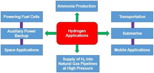
Given its wide range of uses and applications, hydrogen is a significantly important energy source. Several industries including chemical, refining, metallurgy, glass, hydrogen fueled cars, fuel cells and electronics, currently use it (Fig. 11). The main application of hydrogen is as a reactant. Its usage in petroleum refining has recently increased significantly due to a combination of variables related to changes in regulations of crude oil because of the healthy environmental conditions, such as, sulphur limitations for diesel, permitted limits for NOx and SOx in off-gas emissions to the atmosphere, petrol contains high quantities of aromatic and light hydrocarbons, etc.7.1. Ammonia production
The Habere–Bosch process is used to commercially produce ammonia from hydrogen and ambient nitrogen. It is not economically feasible and has a low energy efficiency to produce ammonia from hydrogen and then break down ammonia to produce hydrogen. Ammonia is desirable for mobile applications, where ease of storage and energy density are the main priorities. Hydrogen was produced from ammonia through a breakdown reaction experimentally by Huang et al.136 using Ru or Cs–Ru (cesium-ruthenium) as the catalyst. The ammonia decomposition reaction, catalyst deposition and carbon powder pre-treatment were used in their experimental study. They noted that with a Cs–Ru/C (1![[thin space (1/6-em)]](https://www.rsc.org/images/entities/char_2009.gif) :
:![[thin space (1/6-em)]](https://www.rsc.org/images/entities/char_2009.gif) 3) catalyst, the conversion efficiency of ammonia was 90% and the rate of production of hydrogen was achieved at 30 m mol min−1 gcat−1.
3) catalyst, the conversion efficiency of ammonia was 90% and the rate of production of hydrogen was achieved at 30 m mol min−1 gcat−1.
Life cycle analysis shows that Global warming potential of ammonia is lower that the global average.137 Ammonia is a chemical element that is readily produced from hydrogen, a substance that is found in many products around the world, and nitrogen, which makes up the majority of the atmosphere. With its appealing qualities like high energy density and efficiency, this chemical has a vital role to play in a sustainable future.138 According to Matzen et al.139 ammonia is an indirect hydrogen storage molecule since it contains 17.6 wt% hydrogen. The energy density of ammonia is 4.32 kW h l−1, about twice that of liquid hydrogen, and comparable to that of methanol (CH3OH) (Fig. 12).140
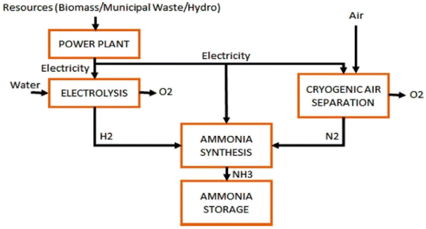 | ||
| Fig. 12 [Fig. 9 ammonia production via hydrogen electrolysis and H–B process.] Adapted from Valera-Medina, A., Xiao, H., Owen-Jones, M., David, W. I., & Bowen, P. J., Ammonia for power. Progress in Energy and combustion science, 2018, 69, 63–102, DOI: 10.1016/j.pecs.2018.07.001. | ||
7.2. Fuel cells
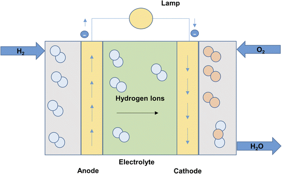
A fuel cell is an electrochemical device that converts chemical energy into electrical energy. The hydrogen is being used as a fuel in the fuel cells. Fuel cells are classified based on the electrolyte substance employed. Proton exchange membrane, alkali, phosphoric acid, solid oxide, and molten carbonate are some examples of electrolytes. The phosphoric acid fuel cell (PAFC) was developed in the year 1960. The schematic of a PAFC is shown in Fig. 13 a typical PAFC cell has two electrodes made commonly of nickel and the electrolyte between the electrodes is phosphoric acid. Few fuel cells use solid electrolytes as well. The fuel which is hydrogen or hydrogen rich gas is supplied at the anode and oxygen is supplied at cathode. Platinum is used as catalyst for enhancing the chemical reaction.141 The anode's fuel, H2, releases electrons that are then delivered to the cathode, where oxygen interacts to generate water, through an external load. The reactions taking place at the anode and cathode of a PAFC cell is as follows:120| Reaction at anode: H2 → 2H+ + 2e− |
| Reaction at cathode: ½O2 + 2H+ + 2e− → H2O |
| Overall reaction: H2 + ½O2 → H2O |
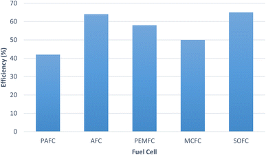
In fuel cell hydrogen is the primary fuel and is the main source of energy. There is a wide range of fuels which can be used in fuel cells. They are classified as direct type fuel and indirect type fuel. In case of direct type, the fuels can be directly introduced in the fuel cell without any pre-treatment, whereas in case of indirect type, these require pre-treatment and reforming. Hydrazine (N2H4), hydrogen, liquid hydrocarbons, methanol, ammonia are few of the common fuels used in fuel cells.142 The plot shows (Fig. 14) the efficiency of the different fuel cells.120
7.3. Hydrogen fueled cars
Since H2 is the fuel with the lowest emissions and is proven to burn more efficiently than gasoline, there is a significant interest in utilizing it as a vehicle fuel. Verhelst and Wallner143 prominently featured the potential of hydrogen as a future energy source. Several manufacturers are already selling hydrogen-fueled internal combustion engines (H2ICEs) and fuel cell vehicles to consumers. To reduce local pollution at a reasonable price, developing countries in particular are pushing for H2ICEs (powering two- and three-wheelers as well as passenger cars and buses). The progress in hydrogen fuel-cell car energy efficiency is examined from the perspective of the supply chain, which includes the government, manufacturers, suppliers, agencies, and consumers.144 The high cost of fuel cells is due to the use of platinum as a catalyst and the missing fueling infrastructure are the key problem associated with hydrogen fuel car at present time. The hydrogen fuel cell car demand and associated profits rise will rise by proper examination of these problem. Compressed hydrogen storage is used for hydrogen cars, as it offers fast refuelling times, low complexity and long storage durations. Especially fast refuelling times make hydrogen cars attractive compared to battery electric vehicles. Hydrogen car prototypes have been built, however, the development has been limited due to their high cost.1457.4. Supply of hydrogen into natural gas pipelines at high pressure
Understanding the effects of injecting H2 in the natural gas (NG) pipelines is quite important given the potential for H2 to begin decarbonizing the NG network. Since a changeover to a fully functional H2 network cannot happen overnight, it is expected that this transitional period will persist for an extended duration, potentially spanning years or even decades. As a result, this topic has received major interest in recent years.146–149 It is observed by Schouten et al.34 that when H2 is introduced, the energy density decreases. The pressure gradient in the pipelines is bigger when the same amount of gas is transmitted on a volumetric basis when transporting NG than it is when transporting a mixture containing H2. The contrary was observed when the identical quantity of gas was transferred on an energy basis rather than a volumetric basis. According to Deymi-Dashtebayaz et al.,149 the addition of H2 enhanced lower heating value (LHV), the lower and upper flammability limits, compressibility factor and higher heating value (HHV) while lowering the density and Wobbe indices. H2 decreased NG mixture density, according to Witkowski et al.148 They further observed that up to 2% of H2 concentration enhanced the viscosity of ordinary NG, whereas concentrations beyond 2% had the opposite effect.7.5. Integrated gasification fuel cell (IGFC)
An integrated gasification fuel cell, often known as an IGFC, is a type of energy generation technology that integrates the gasification and fuel-cell processes to produce power that is both highly efficient. Moreover, in the integrated gasification fuel cell (IGFC) cycle, SOFCs can be operated in a manner that isolates a carbon dioxide-rich anodic exhaust stream, facilitating effective carbon capture to mitigate concerns regarding greenhouse gas emissions in coal-based power generation. As a fuel for fuel cells, hydrogen is essential to the IGFC procedure. Synthesis gas is produced from coal or biomass in an IGFC system through gasification, which includes reacting the feedstock with a gasifying agent at high temperature and pressure (often oxygen or steam). Carbon monoxide (CO), hydrogen (H2), and a few other gases make up most of synthesis gas. Further, impurities and pollutants, such as, sulphur and particle debris, are cleaned and removed from synthesis gas.The hydrogen-rich syngas is fed to a fuel cell, where it combines with atmospheric oxygen to produce power and water. The fuel cell of an IGFC system relies on hydrogen as a fuel, which combines with oxygen to create electricity. Fuel cells require extremely pure hydrogen and therefore syngas needs to be cleaned and prepared to get rid of any contaminants that can harm the fuel cell.
Recently, several researchers150,151 have focused on developing an eco-friendly and effective Combined Heat and Power (CHP) generation system. For CHP generation systems to operate continuously, fuel cells are the best option.150 In comparison to fuel cells, other biomass-based CHP production technologies have higher particulate matter emissions, larger environmental effects, poorer efficiencies, and less feedstock flexibility.151 The integrated gasification SOFC (IGFC) system is one of the novel systems that researchers have developed. An IGFC power system is like an integrated gasification with Gas Turbine (GT) as the power-generating unit, but instead of GT, it uses a fuel cell. Most research on IGFC systems has been theoretical because these are essentially a new thought in CHP-producing systems. Nonetheless, a few experimental investigations have demonstrated the viability of IGFC systems.152,153
Thus, the utilization of hydrogen in an IGFC system has the potential to offer a more effective and environmental friendly method of producing power from coal and biomass feedstock. However, there are substantial barriers to the broad deployment of IGFC systems, including a high cost of hydrogen production and the requirement of advanced gasification and fuel cell technologies.
8. Economic analysis of hydrogen generation technologies
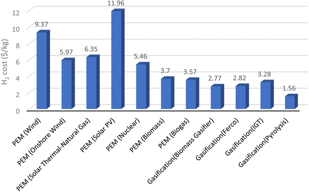
The costs associated with producing, storing, distributing, and utilizing hydrogen must be taken into consideration when evaluating the economics of hydrogen energy systems.154,155 All of these costs are likely to be substantial (in some instances up to 95% (ref. 156) in an era dominated by hydrogen). The cost of producing hydrogen is anticipated to continue to play a significant role in its utilization for the foreseeable future, continuing a trend that has been evident for several decades.The price of the major energy source utilized to produce hydrogen has a significant impact on hydrogen production costs.
8.1. Hydrogen production with electricity
The most popular way to produce hydrogen is the method of electrolysis. Electrolysis costs vary according to the electrical source. Due to fuel costs and related carbon emissions, the cost will be higher if the electricity is produced using fossil fuels. On the other side, the price can be lower and more environmentally benign if electricity is produced using renewable resources. The capital cost of the electrolysis apparatus, maintenance costs, and power costs are all included in the total cost of producing hydrogen using electricity.8.2. Hydrogen production with wind energy
To make hydrogen from wind energy, wind turbines must first produce electricity, which will then be utilized for electrolysis. The price is determined by the initial outlay for wind turbines, maintenance costs, the effectiveness of electrolysis, and the price of power. Factors including the availability of wind resources and the capacity factor of wind turbines will have an impact on the price per kilogram of hydrogen as well.8.3. Hydrogen production with solar energy
Photovoltaic (PV) and solar thermal electrolysis are the two main ways that solar energy can be used to produce hydrogen. PV electrolysis converts sunlight directly into energy, which is then used for electrolysis, using solar panels. On the contrary, solar thermal electrolysis employs concentrated solar power (CSP) to produce high-temperature heat that powers the electrolysis reaction. The cost of producing hydrogen with solar energy relies on the initial investment in solar panels or CSP systems, their upkeep, the effectiveness of electrolysis, and the accessibility of solar resources in the area.Projecting future expenses of conventional and non-conventional hydrogen production technologies is often difficult. Numerous aspects need to be considered, including variations in the price of labor, capital, and feedstocks. Every situation that is taken into consideration needs a new study because these characteristics can differ significantly from one country to the other.
The total production and transportation expenses can be used to calculate the cost of hydrogen energy (CH) which is written as:16
| CH = Cp + CT + CS | (1) |
| Cp = CE + Cw + CF + Co + CM | (2) |
| Hydrogen production method | Energy efficiency | H2 cost range (USD per kilogram) | Key factors |
|---|---|---|---|
| Steam methane reforming (SMR) | 74–85% | 0.75 | Natural gas prices, SMR plant efficiency, carbon capture and storage (CCS) costs |
| Coal gasification | 63% | 0.92 | Established, cost-efficient |
| Electrolysis (PEM) | 60–80% | 2.56–2.97 | Electricity prices, electrolyzer efficiency, capital costs |
| Electrolysis (alkaline) | 59–70% | 1.5–5.0 | Electricity prices, electrolyzer efficiency, capital costs |
| Biomass gasification | 56% | 1.21–2.42 | Biomass feedstock costs, gasification plant efficiency, CCS costs |
| Photoelectrochemical (PEC) | 10–14% | 4.98 | Solar cell efficiency, capital costs, catalyst costs |
| Nuclear thermochemical | 42% | 2.01 | Nuclear power plant costs, thermochemical process efficiency |
| Solar water splitting | 10–14% | 5.0 | Solar panel efficiency, capital costs, catalyst costs |
9. Summary
It is evident from the above review that hydrogen is one of the most promising future energy carriers. Researchers have given numerous efforts to study generation of renewable hydrogen with the help of different techniques such as water splitting, thermochemical conversion of biomass, thermolysis and biophotolysis. These processes of hydrogen production do not produce any toxic substances and are environment friendly.In the thermochemical conversion, a series of chemical reactions (such as oxidation reaction, boudard reaction, steam reaction etc.) takes place within the reactor to produce combustible gas mixture consisting primarily of hydrogen, carbon monoxide, methane, and carbon dioxide. The amount of hydrogen in the gas mixture can be increased by promoting water gas shift reaction. Advanced gasification technologies also help in augmenting the hydrogen percentage in the overall output.
Fermentation (dark and light fermentation) and biophotolysis are technologies of biological conversion which are considered to be sustainable and environment friendly. In biophotolysis many phototropic microorganisms are utilized for hydrogen generation. In dark fermentation, the hydrogen yield is low but the reactor designs are simpler and hence more research is oriented towards dark fermentation.
The success of the hydrogen economy depends on hydrogen production methods, purification and storage technologies and finally, end user applications. Various applications require high purity of hydrogen for which purification technologies such as membrane separation and pressure swing adsorption methods are used. In membrane separation technology, the membrane allows hydrogen to permeate through it and other gases are separated from pure hydrogen. Pressure swing adsorption on the other hand, uses adsorption and desorption for purification. Many researchers have studied various ways of storing hydrogen such as in metal hydride form, in compressed form and in cryogenic form. Metal hydrides being solid state storage provides ease of handling and better duration of storage and can be used to transport hydrogen over longer distances. Researchers also reveal the usefulness of hydrogen in various applications such as in ammonia production, automotive sector, in fuel cells for electricity production and in integrated gasification fuel cell cycle. An economic analysis of hydrogen energy is also carried out to show the cost comparison of various hydrogen generation technologies. It can be summarized that in order to realize the hydrogen economy, this field requires development of efficient, effective and reliable methods of generation, purification and storage. Moreover, the cost involved in hydrogen generation, purification and storage must also be reduced for people to realize the benefits of hydrogen as an energy carrier for the present and future.
Nomenclature
| AR | Air reactor |
| CaCO3 | Calcium carbonate |
| CH | Cost of hydrogen energy |
| CP | Cost of production |
| CT | Cost of transportation |
| CS | Cost of storage |
| CW | Cost of water |
| CF | Cost of production facility |
| CO | Cost of operation |
| CM | Cost of maintenance |
| ER | Equivalence ratio |
| FR | Fuel reactor |
| GT | Gas turbine |
| MexOy | Metal oxides |
| PEC | photoelectrochemical |
| PEM | Proton exchange membrane |
| K2CO3 | Potassium carbonate |
| KOH | Potassium hydroxide |
| NaOH | Sodium hydroxide |
Author contributions
Mrinmoy Kumar Sarmah: investigation, validation, data curation, methodology, resources, software, formal analysis, writing – original draft. Tej Pratap Singh: investigation, validation, data curation, methodology, resources, software, formal analysis, writing – original draft. Pankaj Kalita: conceptualization, visualization, supervision, writing – review & editing, Anupam Dewan: supervision, visualization, writing – review & editing.Conflicts of interest
The authors declare that they have no known competing financial interests or personal relationships that could have appeared to influence the work reported in this paper.References
- S. E. Hosseini, A. M. Andwari, M. A. Wahid and G. Bagheri, A review on green energy potentials in Iran, Renewable Sustainable Energy Rev., 2013, 27, 533–545, DOI:10.1016/j.rser.2013.07.015.
- P. Ibarra-Gonzalez and B.-G. Rong, A review of the current state of biofuels production from lignocellulosic biomass using thermochemical conversion routes, Chin. J. Chem. Eng., 2019, 27(7), 1523–1535, DOI:10.1016/j.cjche.2018.09.018.
- S. Z. Baykara, Hydrogen: A brief overview on its sources, production and environmental impact, Int. J. Hydrogen Energy, 2018, 43(23), 10605–10614, DOI:10.1016/j.ijhydene.2018.02.022.
- E. Biagini, L. Masoni and L. Tognotti, Comparative study of thermochemical processes for hydrogen production from biomass fuels, Bioresour. Technol., 2010, 101(16), 6381–6388, DOI:10.1016/j.biortech.2010.03.052.
- M. Granovskii, I. Dincer and M. A. Rosen, Economic and environmental comparison of conventional, hybrid, electric and hydrogen fuel cell vehicles, J. Power Sources, 2006, 159(2), 1186–1193, DOI:10.1016/j.jpowsour.2005.11.086.
- S. Dutta, A review on production, storage of hydrogen and its utilization as an energy resource, J. Ind. Eng. Chem., 2014, 20(4), 1148–1156, DOI:10.1016/j.jiec.2013.07.037.
- I. K. Kapdan and F. Kargi, Bio-hydrogen production from waste materials, Enzyme Microb. Technol., 2006, 38(5), 569–582, DOI:10.1016/j.enzmictec.2005.09.015.
- R. Chaubey, S. Sahu, O. O. James and S. Maity, A review on development of industrial processes and emerging techniques for production of hydrogen from renewable and sustainable sources, Renewable Sustainable Energy Rev., 2013, 23, 443–462, DOI:10.1016/j.rser.2013.02.019.
- R. Ramachandran, An overview of industrial uses of hydrogen, Int. J. Hydrogen Energy, 1998, 23(7), 593–598, DOI:10.1016/S0360-3199(97)00112-2.
- R. Moradi and K. M. Groth, Hydrogen storage and delivery: Review of the state of the art technologies and risk and reliability analysis, Int. J. Hydrogen Energy, 2019, 44(23), 12254–12269, DOI:10.1016/j.ijhydene.2019.03.041.
- B. N. Stram, Key challenges to expanding renewable energy, Energy Policy, 2016, 96, 728–734, DOI:10.1016/j.enpol.2016.05.034.
- M. M. Rahman, A. O. Oni, E. Gemechu and A. Kumar, Assessment of energy storage technologies: A review, Energy Convers. Manage., 2020, 223, 113295, DOI:10.1016/j.enconman.2020.113295.
- A. M. Elberry, J. Thakur, A. Santasalo-Aarnio and M. Larmi, Large-scale compressed hydrogen storage as part of renewable electricity storage systems, Int. J. Hydrogen Energy, 2021, 46(29), 15671–15690, DOI:10.1016/j.ijhydene.2021.02.080.
- A. M. Abdalla, S. Hossain, O. B. Nisfindy, A. T. Azad, M. Dawood and A. K. Azad, Hydrogen production, storage, transportation and key challenges with applications: A review, Energy Convers. Manage., 2018, 165, 602–627, DOI:10.1016/j.enconman.2018.03.088.
- S. Niaz, T. Manzoor and A. H. Pandith, Hydrogen storage: Materials, methods and perspectives, Renewable Sustainable Energy Rev., 2015, 50, 457–469, DOI:10.1016/j.rser.2015.05.011.
- M. A. Rosen and S. Koohi-Fayegh, The prospects for hydrogen as an energy carrier: an overview of hydrogen energy and hydrogen energy systems, Energy Ecol. Environ., 2016, 1(1), 10–29, DOI:10.1007/s40974-016-0005-z.
- W. Hall, T. Spencer, G. Renjith, and S. Dayal, “The potential role of hydrogen in India,” p. 49, 2020, [Online]. Available: https://www.sustainablefinance.hsbc.com/-/media/gbm/sustainable/attachments/hydrogen-potential-in-india.pdf Search PubMed.
- V. M. Medisetty, R. Kumar, M. H. Ahmadi, D.-V. N. Vo, A. A. V. Ochoa and R. Solanki, Overview on the Current Status of Hydrogen Energy Research and Development in India, Chem. Eng. Technol., 2020, 43(4), 613–624, DOI:10.1002/ceat.201900496.
- O. Bamisile, et al., Environmental impact of hydrogen production from Southwest China's hydro power water abandonment control, Int. J. Hydrogen Energy, 2020, 45(46), 25587–25598, DOI:10.1016/j.ijhydene.2020.06.289.
- J. W. Andrews, Hydrogen production and carbon sequestration by steam methane reforming and fracking with carbon dioxide, Int. J. Hydrogen Energy, 2020, 45(16), 9279–9284, DOI:10.1016/j.ijhydene.2020.01.231.
- F. Safari and I. Dincer, A review and comparative evaluation of thermochemical water splitting cycles for hydrogen production, Energy Convers. Manage., 2020, 205, 112182, DOI:10.1016/j.enconman.2019.112182.
- S. Shiva Kumar and V. Himabindu, Hydrogen production by PEM water electrolysis – A review, Mater. Sci. Energy Technol., 2019, 2(3), 442–454, DOI:10.1016/j.mset.2019.03.002.
- T. Hisatomi, J. Kubota and K. Domen, Recent advances in semiconductors for photocatalytic and photoelectrochemical water splitting, Chem. Soc. Rev., 2014, 43(22), 7520–7535, 10.1039/C3CS60378D.
- R. Bhandari and R. R. Shah, Hydrogen as energy carrier: Techno-economic assessment of decentralized hydrogen production in Germany, Renewable Energy, 2021, 177, 915–931, DOI:10.1016/j.renene.2021.05.149.
- D. Strmcnik, et al., Improving the hydrogen oxidation reaction rate by promotion of hydroxyl adsorption, Nat. Chem., 2013, 5(4), 300–306, DOI:10.1038/nchem.1574.
- L. Xie, Q. Liu, X. Shi, A. M. Asiri, Y. Luo and X. Sun, Superior alkaline hydrogen evolution electrocatalysis enabled by an ultrafine PtNi nanoparticle-decorated Ni nanoarray with ultralow Pt loading, Inorg. Chem. Front., 2018, 5(6), 1365–1369, 10.1039/C8QI00120K.
- S. Schiebahn, T. Grube, M. Robinius, V. Tietze, B. Kumar and D. Stolten, Power to gas: Technological overview, systems analysis and economic assessment for a case study in Germany, Int. J. Hydrogen Energy, 2015, 40(12), 4285–4294, DOI:10.1016/j.ijhydene.2015.01.123.
- J. Chi and H. Yu, Water electrolysis based on renewable energy for hydrogen production, Chin. J. Catal., 2018, 39(3), 390–394, DOI:10.1016/S1872-2067(17)62949-8.
- K. Zeng and D. Zhang, Recent progress in alkaline water electrolysis for hydrogen production and applications, Prog. Energy Combust. Sci., 2010, 36(3), 307–326, DOI:10.1016/j.pecs.2009.11.002.
- P. VERMEIREN, Evaluation of the ZirfonS separator for use in alkaline water electrolysis and Ni-H2 batteries, Int. J. Hydrogen Energy, 1998, 23(5), 321–324, DOI:10.1016/S0360-3199(97)00069-4.
- A. Marinkas, et al., Anion-conductive membranes based on 2-mesityl-benzimidazolium functionalised poly(2,6-dimethyl-1,4-phenylene oxide) and their use in alkaline water electrolysis, Polymer, 2018, 145, 242–251, DOI:10.1016/j.polymer.2018.05.008.
- B. Chakrabarty, A. K. Ghoshal and M. K. Purkait, Preparation, characterization and performance studies of polysulfone membranes using PVP as an additive, J. Membr. Sci., 2008, 315(1–2), 36–47, DOI:10.1016/j.memsci.2008.02.027.
- O. Schmidt, A. Gambhir, I. Staffell, A. Hawkes, J. Nelson and S. Few, Future cost and performance of water electrolysis: An expert elicitation study, Int. J. Hydrogen Energy, 2017, 42(52), 30470–30492, DOI:10.1016/j.ijhydene.2017.10.045.
- A. Buttler and H. Spliethoff, Current status of water electrolysis for energy storage, grid balancing and sector coupling via power-to-gas and power-to-liquids: A review, Renewable Sustainable Energy Rev., 2018, 82, 2440–2454, DOI:10.1016/j.rser.2017.09.003.
- A. Pandiyan, A. Uthayakumar, R. Subrayan, S. W. Cha and S. B. Krishna Moorthy, Review of solid oxide electrolysis cells: a clean energy strategy for hydrogen generation, Nanomater. Energy, 2019, 8(1), 2–22, DOI:10.1680/jnaen.18.00009.
- M. Rafique, et al., A Comprehensive Study on Methods and Materials for Photocatalytic Water Splitting and Hydrogen Production as a Renewable Energy Resource, J. Inorg. Organomet. Polym. Mater., 2020, 30(10), 3837–3861, DOI:10.1007/s10904-020-01611-9.
- S. Abanades and G. Flamant, Thermochemical hydrogen production from a two-step solar-driven water-splitting cycle based on cerium oxides, Sol. Energy, 2006, 80(12), 1611–1623, DOI:10.1016/j.solener.2005.12.005.
- S. Baykara, Experimental solar water thermolysis, Int. J. Hydrogen Energy, 2004, 29(14), 1459–1469, DOI:10.1016/j.ijhydene.2004.02.011.
- S. Baykara and E. Bilgen, An overall assessment of hydrogen production by solar water thermolysis, Int. J. Hydrogen Energy, 1989, 14(12), 881–891, DOI:10.1016/0360-3199(89)90075-X.
- J. E. Funk, Thermochemical hydrogen production: past and present, Int. J. Hydrogen Energy, 2001, 26(3), 185–190, DOI:10.1016/S0360-3199(00)00062-8.
- S. Liu, J. Zhu, M. Chen, W. Xin, Z. Yang and L. Kong, Hydrogen production via catalytic pyrolysis of biomass in a two-stage fixed bed reactor system, Int. J. Hydrogen Energy, 2014, 39(25), 13128–13135, DOI:10.1016/j.ijhydene.2014.06.158.
- A. Demirbaş, Biomass resource facilities and biomass conversion processing for fuels and chemicals, Energy Convers. Manage., 2001, 42(11), 1357–1378, DOI:10.1016/S0196-8904(00)00137-0.
- A. Demirbaş, Yields of hydrogen-rich gaseous products via pyrolysis from selected biomass samples, Fuel, 2001, 80(13), 1885–1891, DOI:10.1016/S0016-2361(01)00070-9.
- R. K. Jalan and V. K. Srivastava, Studies on pyrolysis of a single biomass cylindrical pellet—kinetic and heat transfer effects, Energy Convers. Manage., 1999, 40(5), 467–494, DOI:10.1016/S0196-8904(98)00099-5.
- A. Demirbaş, Gaseous products from biomass by pyrolysis and gasification: effects of catalyst on hydrogen yield, Energy Convers. Manage., 2002, 43(7), 897–909, DOI:10.1016/S0196-8904(01)00080-2.
- L. Garcia, M. L. Salvador, J. Arauzo and R. Bilbao, Influence of Catalyst Weight/Biomass Flow Rate Ratio on Gas Production in the Catalytic Pyrolysis of Pine Sawdust at Low Temperatures, Ind. Eng. Chem. Res., 1998, 37(10), 3812–3819, DOI:10.1021/ie9801960.
- G. Chen, J. Andries and H. Spliethoff, Catalytic pyrolysis of biomass for hydrogen rich fuel gas production, Energy Convers. Manage., 2003, 44(14), 2289–2296, DOI:10.1016/S0196-8904(02)00254-6.
- P. T. Williams and A. J. Brindle, Catalytic pyrolysis of tyres: influence of catalyst temperature, Fuel, 2002, 81(18), 2425–2434, DOI:10.1016/S0016-2361(02)00196-5.
- I. Narváez, J. Corella and A. Orío, Fresh Tar (from a Biomass Gasifier) Elimination over a Commercial Steam-Reforming Catalyst. Kinetics and Effect of Different Variables of Operation, Ind. Eng. Chem. Res., 1997, 36(2), 317–327, DOI:10.1021/ie960235c.
- Y. Wang, L. Huang, T. Zhang and Q. Wang, Hydrogen-rich syngas production from biomass pyrolysis and catalytic reforming using biochar-based catalysts, Fuel, 2022, 313, 123006, DOI:10.1016/j.fuel.2021.123006.
- C. Loha, P. K. Chatterjee and H. Chattopadhyay, Performance of fluidized bed steam gasification of biomass – Modeling and experiment, Energy Convers. Manage., 2011, 52(3), 1583–1588, DOI:10.1016/j.enconman.2010.11.003.
- H. Song, et al., Recent development of biomass gasification for H2 rich gas production, Appl. Energy Combust. Sci., 2022, 10, 100059, DOI:10.1016/j.jaecs.2022.100059.
- N. Chanburanasiri, et al., Hydrogen Production via Sorption Enhanced Steam Methane Reforming Process Using Ni/CaO Multifunctional Catalyst, Ind. Eng. Chem. Res., 2011, 50(24), 13662–13671, DOI:10.1021/ie201226j.
- H. Guan, et al., An experimental investigation on biogases production from Chinese herb residues based on dual circulating fluidized bed, Int. J. Hydrogen Energy, 2018, 43(28), 12618–12626, DOI:10.1016/j.ijhydene.2018.05.141.
- W. Li, Q. Li, R. Chen, Y. Wu and Y. Zhang, Investigation of hydrogen production using wood pellets gasification with steam at high temperature over 800 °C to 1435 °C, Int. J. Hydrogen Energy, 2014, 39(11), 5580–5588, DOI:10.1016/j.ijhydene.2014.01.102.
- L. Briesemeister, M. Kremling, S. Fendt and H. Spliethoff, Air-Blown Entrained-Flow Gasification of Biomass: Influence of Operating Conditions on Tar Generation, Energy Fuels, 2017, 31(10), 10924–10932, DOI:10.1021/acs.energyfuels.7b01801.
- M. Al-Zareer, I. Dincer and M. A. Rosen, Influence of Selected Gasification Parameters on Syngas Composition From Biomass Gasification, J. Energy Resour. Technol., 2018, 140(4), 041803, DOI:10.1115/1.4039601.
- A. Demirbaş, Hydrogen Production from Biomass by the Gasification Process, Energy Sources, 2002, 24(1), 59–68, DOI:10.1080/00908310252712307.
- G. N. Shelke and P. Mahanta, Feasibility study on utilization of biomass briquette in a conventional downdraft gasifier, Int. Energy J., 2015, 15(4), 157–166 Search PubMed.
- A. Molino, S. Chianese and D. Musmarra, Biomass gasification technology: The state of the art overview, J. Energy Chem., 2016, 25(1), 10–25, DOI:10.1016/j.jechem.2015.11.005.
- P. McKendry, Energy production from biomass (part 3): gasification technologies, Bioresour. Technol., 2002, 83(1), 55–63, DOI:10.1016/S0960-8524(01)00120-1.
- J. Ren, Y.-L. Liu, X.-Y. Zhao and J.-P. Cao, Biomass thermochemical conversion: A review on tar elimination from biomass catalytic gasification, J. Energy Inst., 2020, 93(3), 1083–1098, DOI:10.1016/j.joei.2019.10.003.
- H. Ge, H. Zhang, W. Guo, T. Song and L. Shen, System simulation and experimental verification: Biomass-based integrated gasification combined cycle (BIGCC) coupling with chemical looping gasification (CLG) for power generation, Fuel, 2019, 241, 118–128, DOI:10.1016/j.fuel.2018.11.091.
- C. Couhert, S. Salvador and J.-M. Commandré, Impact of torrefaction on syngas production from wood, Fuel, 2009, 88(11), 2286–2290, DOI:10.1016/j.fuel.2009.05.003.
- Y.-D. Kim, S.-H. Jung, J. Jeong, W. Yang and U.-D. Lee, Production of producer gas from waste cooking oil in a fluidized bed reactor: Influence of low-temperature oxidation of fuel, Fuel, 2015, 146, 125–131, DOI:10.1016/j.fuel.2015.01.020.
- R. C. Saxena, D. K. Adhikari and H. B. Goyal, Biomass-based energy fuel through biochemical routes: A review, Renewable Sustainable Energy Rev., 2009, 13(1), 167–178, DOI:10.1016/j.rser.2007.07.011.
- M. Y. Azwar, M. A. Hussain and A. K. Abdul-Wahab, Development of biohydrogen production by photobiological, fermentation and electrochemical processes: A review, Renewable Sustainable Energy Rev., 2014, 31, 158–173, DOI:10.1016/j.rser.2013.11.022.
- L. B. Brentner, J. Peccia and J. B. Zimmerman, Challenges in Developing Biohydrogen as a Sustainable Energy Source: Implications for a Research Agenda, Environ. Sci. Technol., 2010, 44(7), 2243–2254, DOI:10.1021/es9030613.
- B. D. Kossalbayev, et al., Determination of the potential of cyanobacterial strains for hydrogen production, Int. J. Hydrogen Energy, 2020, 45(4), 2627–2639, DOI:10.1016/j.ijhydene.2019.11.164.
- H. Argun, F. Kargi, I. Kapdan and R. Oztekin, Biohydrogen production by dark fermentation of wheat powder solution: Effects of C/N and C/P ratio on hydrogen yield and formation rate, Int. J. Hydrogen Energy, 2008, 33(7), 1813–1819, DOI:10.1016/j.ijhydene.2008.01.038.
- C. N. C. Hitam and A. A. Jalil, A review on biohydrogen production through photo-fermentation of lignocellulosic biomass, Biomass Convers. Biorefin., 2023, 13, 8465–8483, DOI:10.1007/s13399-020-01140-y.
- R. Łukajtis, et al., Hydrogen production from biomass using dark fermentation, Renewable Sustainable Energy Rev., 2018, 91, 665–694, DOI:10.1016/j.rser.2018.04.043.
- A. Züttel, Hydrogen storage methods, Naturwissenschaften, 2004, 91(4), 157–172, DOI:10.1007/s00114-004-0516-x.
- D. A. J. Rand, A journey on the electrochemical road to sustainability, J. Solid State Electrochem., 2011, 15(7–8), 1579–1622, DOI:10.1007/s10008-011-1410-z.
- N. Nipattummakul, I. I. Ahmed, A. K. Gupta and S. Kerdsuwan, Hydrogen and syngas yield from residual branches of oil palm tree using steam gasification, Int. J. Hydrogen Energy, 2011, 36(6), 3835–3843, DOI:10.1016/j.ijhydene.2010.04.102.
- H. de Lasa, E. Salaices, J. Mazumder and R. Lucky, Catalytic Steam Gasification of Biomass: Catalysts, Thermodynamics and Kinetics, Chem. Rev., 2011, 111(9), 5404–5433, DOI:10.1021/cr200024w.
- N. H. Florin and A. T. Harris, Enhanced hydrogen production from biomass with in situ carbon dioxide capture using calcium oxide sorbents, Chem. Eng. Sci., 2008, 63(2), 287–316, DOI:10.1016/j.ces.2007.09.011.
- Y.-S. Jeong, K.-B. Park and J.-S. Kim, Hydrogen production from steam gasification of polyethylene using a two-stage gasifier and active carbon, Appl. Energy, 2020, 262, 114495, DOI:10.1016/j.apenergy.2020.114495.
- S. Fremaux, S.-M. Beheshti, H. Ghassemi and R. Shahsavan-Markadeh, An experimental study on hydrogen-rich gas production via steam gasification of biomass in a research-scale fluidized bed, Energy Convers. Manage., 2015, 91, 427–432, DOI:10.1016/j.enconman.2014.12.048.
- C. Gai, Y. Guo, T. Liu, N. Peng and Z. Liu, Hydrogen-rich gas production by steam gasification of hydrochar derived from sewage sludge, Int. J. Hydrogen Energy, 2016, 41(5), 3363–3372, DOI:10.1016/j.ijhydene.2015.12.188.
- Z. Khan, S. Yusup, M. M. Ahmad and N. A. Rashidi, Integrated catalytic adsorption (ICA) steam gasification system for enhanced hydrogen production using palm kernel shell, Int. J. Hydrogen Energy, 2014, 39(7), 3286–3293, DOI:10.1016/j.ijhydene.2013.12.020.
- J. Li, J. Liu, S. Liao and R. Yan, Hydrogen-rich gas production by air–steam gasification of rice husk using supported nano-NiO/γ-Al2O3 catalyst, Int. J. Hydrogen Energy, 2010, 35(14), 7399–7404, DOI:10.1016/j.ijhydene.2010.04.108.
- R. Alipour Moghadam, S. Yusup, W. Azlina, S. Nehzati and A. Tavasoli, Investigation on syngas production via biomass conversion through the integration of pyrolysis and air–steam gasification processes, Energy Convers. Manage., 2014, 87, 670–675, DOI:10.1016/j.enconman.2014.07.065.
- N. GAO, A. LI, C. QUAN and F. GAO, Hydrogen-rich gas production from biomass steam gasification in an updraft fixed-bed gasifier combined with a porous ceramic reformer, Int. J. Hydrogen Energy, 2008, 33(20), 5430–5438, DOI:10.1016/j.ijhydene.2008.07.033.
- A. Kruse, Supercritical water gasification, Biofuels, Bioprod. Biorefin., 2008, 2(5), 415–437, DOI:10.1002/bbb.93.
- O. Yakaboylu, J. Harinck, K. Smit and W. de Jong, Supercritical Water Gasification of Biomass: A Literature and Technology Overview, Energies, 2015, 8(2), 859–894, DOI:10.3390/en8020859.
- S. N. Reddy, S. Nanda, A. K. Dalai and J. A. Kozinski, Supercritical water gasification of biomass for hydrogen production, Int. J. Hydrogen Energy, 2014, 39(13), 6912–6926, DOI:10.1016/j.ijhydene.2014.02.125.
- Y. Hu, M. Gong, X. Xing, H. Wang, Y. Zeng and C. C. Xu, Supercritical water gasification of biomass model compounds: A review, Renewable Sustainable Energy Rev., 2020, 118, 109529, DOI:10.1016/j.rser.2019.109529.
- P. Basu and V. Mettanant, Biomass Gasification in Supercritical Water -- A Review, Int. J. Chem. React. Eng., 2009, 7(1), 1–61, DOI:10.2202/1542-6580.1919.
- J. Delgado, M. P. Aznar and J. Corella, Biomass Gasification with Steam in Fluidized Bed: Effectiveness of CaO, MgO, and CaO−MgO for Hot Raw Gas Cleaning, Ind. Eng. Chem. Res., 1997, 36(5), 1535–1543, DOI:10.1021/ie960273w.
- A. Gómez-Barea, B. Leckner, A. Villanueva Perales, S. Nilsson and D. Fuentes Cano, Improving the performance of fluidized bed biomass/waste gasifiers for distributed electricity: A new three-stage gasification system, Appl. Therm. Eng., 2013, 50(2), 1453–1462, DOI:10.1016/j.applthermaleng.2011.12.025.
- U. Henriksen, et al., The design, construction and operation of a 75kW two-stage gasifier, Energy, 2006, 31(10–11), 1542–1553, DOI:10.1016/j.energy.2005.05.031.
- Z. Chen, S. Zhang, Z. Chen and D. Ding, An integrated process for hydrogen-rich gas production from cotton stalks: The simultaneous gasification of pyrolysis gases and char in an entrained flow bed reactor, Bioresour. Technol., 2015, 198, 586–592, DOI:10.1016/j.biortech.2015.09.015.
- R. Zhang, J. Zhang, W. Guo, Z. Wu, Z. Wang and B. Yang, Effect of torrefaction pretreatment on biomass chemical looping gasification (BCLG) characteristics: Gaseous products distribution and kinetic analysis, Energy Convers. Manage., 2021, 237, 114100, DOI:10.1016/j.enconman.2021.114100.
- Y. Wu, Y. Liao, G. Liu and X. Ma, Syngas production by chemical looping gasification of biomass with steam and CaO additive, Int. J. Hydrogen Energy, 2018, 43(42), 19375–19383, DOI:10.1016/j.ijhydene.2018.08.197.
- P. Dieringer, F. Marx, F. Alobaid, J. Ströhle and B. Epple, Process Control Strategies in Chemical Looping Gasification—A Novel Process for the Production of Biofuels Allowing for Net Negative CO2 Emissions, Appl. Sci., 2020, 10(12), 4271, DOI:10.3390/app10124271.
- N. M. Nguyen, F. Alobaid, P. Dieringer and B. Epple, Biomass-Based Chemical Looping Gasification: Overview and Recent Developments, Appl. Sci., 2021, 11(15), 7069, DOI:10.3390/app11157069.
- H. Weldekidan, V. Strezov and G. Town, Review of solar energy for biofuel extraction, Renewable Sustainable Energy Rev., 2018, 88, 184–192, DOI:10.1016/j.rser.2018.02.027.
- S. Möller, D. Kaucic and C. Sattler, Hydrogen Production by Solar Reforming of Natural Gas: A Comparison Study of Two Possible Process Configurations, J. Sol. Energy Eng., 2006, 128(1), 16–23, DOI:10.1115/1.2164447.
- Q. Bellouard, S. Rodat, S. Abanades, S. Ravel and P.-É. Frayssines, Design, simulation and experimental study of a directly-irradiated solar chemical reactor for hydrogen and syngas production from continuous solar-driven wood biomass gasification, Int. J. Hydrogen Energy, 2019, 44(35), 19193–19205, DOI:10.1016/j.ijhydene.2018.04.147.
- Z. Du, et al., A Review of Hydrogen Purification Technologies for Fuel Cell Vehicles, Catalysts, 2021, 11(3), 393, DOI:10.3390/catal11030393.
- T. Yurata, et al., Feasibility and sustainability analyses of carbon dioxide – hydrogen separation via de-sublimation process in comparison with other processes, Int. J. Hydrogen Energy, 2019, 44(41), 23120–23134, DOI:10.1016/j.ijhydene.2019.07.032.
- X. He, L. Lei and Z. Dai, Green hydrogen enrichment with carbon membrane processes: Techno-economic feasibility and sensitivity analysis, Sep. Purif. Technol., 2021, 276, 119346, DOI:10.1016/j.seppur.2021.119346.
- L. Lei, A. Lindbråthen, M. Hillestad and X. He, Carbon molecular sieve membranes for hydrogen purification from a steam methane reforming process, J. Membr. Sci., 2021, 627, 119241, DOI:10.1016/j.memsci.2021.119241.
- L. Tong, P. Bénard, Y. Zong, R. Chahine, K. Liu and J. Xiao, Artificial neural network based optimization of a six-step two-bed pressure swing adsorption system for hydrogen purification, Energy AI, 2021, 5, 100075, DOI:10.1016/j.egyai.2021.100075.
- P. Li, et al., Recent developments in membranes for efficient hydrogen purification, J. Membr. Sci., 2015, 495, 130–168, DOI:10.1016/j.memsci.2015.08.010.
- D.-W. Lee, B. Sea, K.-Y. Lee and K.-H. Lee, Preparation and Characterizaton of SiO 2 Composite Membranes for Purification of Hydrogen for PEMFC, Ind. Eng. Chem. Res., 2002, 41(15), 3594–3600, DOI:10.1021/ie010853f.
- T. Wu, N. Prasetya and K. Li, Recent advances in aluminium-based metal-organic frameworks (MOF) and its membrane applications, J. Membr. Sci., 2020, 615, 118493, DOI:10.1016/j.memsci.2020.118493.
- S. Liguori, K. Kian, N. Buggy, B. H. Anzelmo and J. Wilcox, Opportunities and challenges of low-carbon hydrogen via metallic membranes, Prog. Energy Combust. Sci., 2020, 80, 100851, DOI:10.1016/j.pecs.2020.100851.
- S. SIRCAR and T. C. GOLDEN, Purification of Hydrogen by Pressure Swing Adsorption, Sep. Sci. Technol., 2000, 35(5), 667–687, DOI:10.1081/SS-100100183.
- H. T. J. Reijers, S. E. A. Valster-Schiermeier, P. D. Cobden and R. W. van den Brink, Hydrotalcite as CO 2 Sorbent for Sorption-Enhanced Steam Reforming of Methane, Ind. Eng. Chem. Res., 2006, 45(8), 2522–2530, DOI:10.1021/ie050563p.
- S. Kuroda, T. Nagaishi, M. Kameyama, K. Koido, Y. Seo and K. Dowaki, Hydroxyl aluminium silicate clay for biohydrogen purification by pressure swing adsorption: Physical properties, adsorption isotherm, multicomponent breakthrough curve modelling, and cycle simulation, Int. J. Hydrogen Energy, 2018, 43(34), 16573–16588, DOI:10.1016/j.ijhydene.2018.07.065.
- A. Abdeljaoued, F. Relvas, A. Mendes and M. H. Chahbani, Simulation and experimental results of a PSA process for production of hydrogen used in fuel cells, J. Environ. Chem. Eng., 2018, 6(1), 338–355, DOI:10.1016/j.jece.2017.12.010.
- C. Song, Q. Liu, S. Deng, H. Li and Y. Kitamura, Cryogenic-based CO2 capture technologies: State-of-the-art developments and current challenges, Renewable Sustainable Energy Rev., 2019, 101, 265–278, DOI:10.1016/j.rser.2018.11.018.
- P. Muthukumar, A. Satheesh, U. Madhavakrishna and A. Dewan, Numerical investigation of coupled heat and mass transfer during desorption of hydrogen in metal hydride beds, Energy Convers. Manage., 2009, 50(1), 69–75, DOI:10.1016/j.enconman.2008.08.028.
- A. Satheesh, P. Muthukumar and A. Dewan, Computational study of metal hydride cooling system, Int. J. Hydrogen Energy, 2009, 34(7), 3164–3172, DOI:10.1016/j.ijhydene.2009.01.083.
- P. Muthukumar, U. Madhavakrishna and A. Dewan, Parametric studies on a metal hydride based hydrogen storage device, Int. J. Hydrogen Energy, 2007, 32(18), 4988–4997, DOI:10.1016/j.ijhydene.2007.08.010.
- G. Alefeld and J. Völkl, Hydrogen in Metals II, Springer Berlin Heidelberg, Berlin, Heidelberg, vol. 29, 1978. DOI:10.1007/3-540-08883-0.
- M. Gupta and L. Schlapbach, Hydrogen in intermetallic compounds I, Top. Appl. Phys., 1988, 63, 412, DOI:10.1002/crat.2170240416.
- B. H. Khan, Non-Conventional Energy Resources, 2nd edn, 2006 Search PubMed.
- W. M. Haynes, D. R. Lide, and T. J. Bruno, CRC Handbook of Chemistry and Physics, CRC Press, 2016, DOI:10.1201/9781315380476.
- A. Zaluska, L. Zaluski and J. O. Ström-Olsen, Structure, catalysis and atomic reactions on the nano-scale: a systematic approach to metal hydrides for hydrogen storage, Appl. Phys. A: Mater. Sci. Process., 2001, 72(2), 157–165, DOI:10.1007/s003390100783.
- W. Grochala and P. P. Edwards, Thermal Decomposition of the Non-Interstitial Hydrides for the Storage and Production of Hydrogen, Chem. Rev., 2004, 104(3), 1283–1316, DOI:10.1021/cr030691s.
- H. Imamura, K. Masanari, M. Kusuhara, H. Katsumoto, T. Sumi and Y. Sakata, High hydrogen storage capacity of nanosized magnesium synthesized by high energy ball-milling, J. Alloys Compd., 2005, 386(1–2), 211–216, DOI:10.1016/j.jallcom.2004.04.145.
- L. Zaluski, A. Zaluska and J. . Ström-Olsen, Nanocrystalline metal hydrides, J. Alloys Compd., 1997, 253(254), 70–79, DOI:10.1016/S0925-8388(96)02985-4.
- M. Zhu, H. Wang, L. Ouyang and M. Zeng, Composite structure and hydrogen storage properties in Mg-base alloys, Int. J. Hydrogen Energy, 2006, 31(2), 251–257, DOI:10.1016/j.ijhydene.2005.04.030.
- Y. Fukai, The Metal-Hydrogen System, Berlin, Heidelberg, Springer Berlin Heidelberg, vol. 21, 2005, DOI:10.1007/3-540-28883-X.
- A. Zaluska, L. Zaluski and J. . Ström-Olsen, Nanocrystalline magnesium for hydrogen storage, J. Alloys Compd., 1999, 288(1–2), 217–225, DOI:10.1016/S0925-8388(99)00073-0.
- G. Barkhordarian, T. Klassen and R. Bormann, Effect of Nb2O5 content on hydrogen reaction kinetics of Mg, J. Alloys Compd., 2004, 364(1–2), 242–246, DOI:10.1016/S0925-8388(03)00530-9.
- B. Bogdanović, et al., Thermodynamic investigation of the magnesium–hydrogen system, J. Alloys Compd., 1999, 282(1–2), 84–92, DOI:10.1016/S0925-8388(98)00829-9.
- S. M. Aceves, et al., High-density automotive hydrogen storage with cryogenic capable pressure vessels, Int. J. Hydrogen Energy, 2010, 35(3), 1219–1226, DOI:10.1016/j.ijhydene.2009.11.069.
- R. K. Ahluwalia, J.-K. Peng, and T. Q. Hua, “Cryo-compressed hydrogen storage,” in Compendium of Hydrogen Energy, Elsevier, 2016, pp. 119–145, DOI:10.1016/B978-1-78242-362-1.00005-5.
- H. Barthelemy, M. Weber and F. Barbier, Hydrogen storage: Recent improvements and industrial perspectives, Int. J. Hydrogen Energy, 2017, 42(11), 7254–7262, DOI:10.1016/j.ijhydene.2016.03.178.
- M. R. Usman, Hydrogen storage methods: Review and current status, Renewable Sustainable Energy Rev., 2022, 167, 112743, DOI:10.1016/j.rser.2022.112743.
- B. Zohuri, “Cryogenics and Liquid Hydrogen Storage,” in Hydrogen Energy, Cham, Springer International Publishing, 2019, pp. 121–139, DOI:10.1007/978-3-319-93461-7_4.
- D.-C. Huang, C.-H. Jiang, F.-J. Liu, Y.-C. Cheng, Y.-C. Chen and K.-L. Hsueh, Preparation of Ru–Cs catalyst and its application on hydrogen production by ammonia decomposition, Int. J. Hydrogen Energy, 2013, 38(8), 3233–3240, DOI:10.1016/j.ijhydene.2012.10.105.
- A. Makhlouf, T. Serradj and H. Cheniti, Life cycle impact assessment of ammonia production in Algeria: A comparison with previous studies, Environ. Impact Assess. Rev., 2015, 50, 35–41, DOI:10.1016/j.eiar.2014.08.003.
- İ. Dinçer and C. Zamfirescu, Sustainable Energy Systems and Applications, Boston, MA: Springer US, 2012, DOI:10.1007/978-0-387-95861-3.
- M. J. Matzen, M. H. Alhajji and Y. Demirel, Technoeconomics and sustainability of renewable methanol and ammonia productions using wind power-based hydrogen, Adv. Chem. Eng., 2015, 5(3), 1–12, DOI:10.4172/2090-4568.1000128.
- S. Ghavam, M. Vahdati, I. A. G. Wilson and P. Styring, Sustainable Ammonia Production Processes, Front. Energy Res., 2021, 9, 580808, DOI:10.3389/fenrg.2021.580808.
- A. C. Bhosale, S. R. Suseendiran, R. Ramya, S. R. Choudhury, and R. Rengaswamy, “Phosphoric Acid Fuel Cells,” in Comprehensive Renewable Energy, Elsevier, 2022, pp. 437–458, DOI:10.1016/B978-0-12-819727-1.00006-6.
- Y. Wang, et al., Microfluidic fuel cells with different types of fuels: A prospective review, Renewable Sustainable Energy Rev., 2021, 141, 110806, DOI:10.1016/j.rser.2021.110806.
- S. Verhelst and T. Wallner, Hydrogen-fueled internal combustion engines, Prog. Energy Combust. Sci., 2009, 35(6), 490–527, DOI:10.1016/j.pecs.2009.08.001.
- H. Jafari, E. Azad-Farsani and S. Safarzadeh, Effects of Governmental Policies on Energy-Efficiency Improvement of Hydrogen Fuel Cell Cars: A Game-Theoretic Approach, Energy, 2022, 254, 124394, DOI:10.2139/ssrn.4018986.
- R. Shinnar, The hydrogen economy, fuel cells, and electric cars, Technol. Soc., 2003, 25(4), 455–476, DOI:10.1016/j.techsoc.2003.09.024.
- J. A. Schouten, J. P. J. Michels and R. J. Rosmalen, Effect of H2-injection on the thermodynamic and transportation properties of natural gas, Int. J. Hydrog. Energy, 2004, 29(11), 1173–1180, DOI:10.1016/j.ijhydene.2003.11.003.
- A. A. Abd, S. Z. Naji, T. C. Thian and M. R. Othman, Evaluation of hydrogen concentration effect on the natural gas properties and flow performance, Int. J. Hydrogen Energy, 2021, 46(1), 974–983, DOI:10.1016/j.ijhydene.2020.09.141.
- A. Witkowski, A. Rusin, M. Majkut and K. Stolecka, Comprehensive analysis of hydrogen compression and pipeline transportation from thermodynamics and safety aspects, Energy, 2017, 141, 2508–2518, DOI:10.1016/j.energy.2017.05.141.
- M. Deymi-Dashtebayaz, A. Ebrahimi-Moghadam, S. I. Pishbin and M. Pourramezan, Investigating the effect of hydrogen injection on natural gas thermo-physical properties with various compositions, Energy, 2019, 167, 235–245, DOI:10.1016/j.energy.2018.10.186.
- DOE, US, Department of Energy, Office of Fossil Energy, 2003b, An Energy Overview the Republic of the Republic of Poland, US Department of Energy, Office of Fossil Energy, 2003 Search PubMed.
- C. Moretti, et al., Combining Biomass Gasification and Solid Oxid Fuel Cell for Heat and Power Generation: An Early-Stage Life Cycle Assessment, Energies, 2020, 13(11), 2773, DOI:10.3390/en13112773.
- H. Ghezel-Ayagh et al., Solid Oxide Fuel Cell System Development for Stationary Power Applications,” in ASME 2011 9th International Conference on Fuel Cell Science, Engineering and Technology, 2011, pp. 513–523, DOI:10.1115/FuelCell2011-54921.
- L. Fan, E. Dimitriou, M. J. B. M. Pourquie, M. Liu, A. H. M. Verkooijen and P. V. Aravind, Prediction of the performance of a solid oxide fuel cell fuelled with biosyngas: Influence of different steam-reforming reaction kinetic parameters, Int. J. Hydrogen Energy, 2013, 38(1), 510–524, DOI:10.1016/j.ijhydene.2012.09.061.
- P. Ekins, Hydrogen Energy, Routledge, 2010, DOI:10.4324/9781849774949.
- R. Kothari, D. Buddhi and R. L. Sawhney, Comparison of environmental and economic aspects of various hydrogen production methods, Renewable Sustainable Energy Rev., 2008, 12(2), 553–563, DOI:10.1016/j.rser.2006.07.012.
- A. Ajanovic, On the economics of hydrogen from renewable energy sources as an alternative fuel in transport sector in Austria, Int. J. Hydrogen Energy, 2008, 33(16), 4223–4234, DOI:10.1016/j.ijhydene.2008.06.041.
- P. Parthasarathy and K. S. Narayanan, Hydrogen production from steam gasification of biomass: Influence of process parameters on hydrogen yield – A review, Renewable Energy, 2014, 66, 570–579, DOI:10.1016/j.renene.2013.12.025.
- R. S. El-Emam and H. Özcan, Comprehensive review on the techno-economics of sustainable large-scale clean hydrogen production, J. Cleaner Prod., 2019, 220, 593–609, DOI:10.1016/j.jclepro.2019.01.309.
- B. Olateju, A. Kumar and M. Secanell, A techno-economic assessment of large scale wind-hydrogen production with energy storage in Western Canada, Int. J. Hydrogen Energy, 2016, 41(21), 8755–8776, DOI:10.1016/j.ijhydene.2016.03.177.
- G. Saur and T. Ramsden, “Wind Electrolysis: Hydrogen Cost Optimization,” Golden, CO (United States), 2011, DOI:10.2172/1015505.
- R. Boudries, Techno-economic study of hydrogen production using CSP technology, Int. J. Hydrogen Energy, 2018, 43(6), 3406–3417, DOI:10.1016/j.ijhydene.2017.05.157.
- R. S. El-Emam and I. Khamis, International collaboration in the IAEA nuclear hydrogen production program for benchmarking of HEEP, Int. J. Hydrogen Energy, 2017, 42(6), 3566–3571, DOI:10.1016/j.ijhydene.2016.07.256.
- A. Abuşoğlu, S. Demir and E. Özahi, Energy and economic analyses of models developed for sustainable hydrogen production from biogas-based electricity and sewage sludge, Int. J. Hydrogen Energy, 2016, 41(31), 13426–13435, DOI:10.1016/j.ijhydene.2016.05.105.
- Z. Dobó and Á. B. Palotás, Impact of the current fluctuation on the efficiency of Alkaline Water Electrolysis, Int. J. Hydrogen Energy, 2017, 42(9), 5649–5656, DOI:10.1016/j.ijhydene.2016.11.142.
| This journal is © The Royal Society of Chemistry 2023 |

