 Open Access Article
Creative Commons Attribution 3.0 Unported Licence
Photoelectrocatalytic hydrogen evolution reaction stimulated by the surface plasmon resonance effect of copper and silver surrounded with MoS2†
Yuanyuan Tian *,
Chengnan Qi,
Ruihua Zhou,
Dan Li and
Tao Han
College of Materials Industry, Shanxi College of Technology, Shuozhou, Shanxi Province 036000, China. E-mail: tyy20220418@163.com
First published on 23rd August 2023
Abstract
Developing plasmonic metal-based photocatalysts can improve the photoelectrocatalytic hydrogen evolution reaction (HER) and overcome the limitations of semiconductor-based photocatalysts. A MoS2@Ag–Cu foam composite electrode was fabricated on a copper foam and employed for photoelectrocatalytic HER. The optical behavior and photoelectrocatalytic HER test results indicate that the surface plasmon resonance effect of copper and silver is the primary source of light absorption. Additionally, molybdenum sulfide was employed as a hot-electron trap to capture the energetic electrons generated from copper and silver, thereby promoting the hydrogen evolution reaction. Its binder-free electrode exhibits the better HER performance and excellent stability. Low-cost plasmonic metals, copper and silver, were used as the source of photocatalysis, providing a novel perspective for enhancing photoelectrocatalytic HER performance.
Introduction
Photoelectrocatalytic HER has been identified as one of the best ways to address the energy crisis and environmental pollution.1 The first-generation semiconductor-based photoelectrocatalyst materials were proposed by scientists Fujishima and Honda in the 1970s.2 In the following decades, they were continuously utilized for enhancing photoelectrocatalytic reactions through modification3–6 and decoration.7–11 However, low electric conductivity and narrow window for light absorption12,13 became fatal flaws that limited the HER performance. In recent years, plasmonic metal-based materials, such as precious metal Au,14–17 have been considered a novel and reliable means of boosting the photoelectrocatalytic HER.18,19 Research has shown that plasmonic metals can effectively improve photoelectrocatalytic performance due to their three advantages: the antenna effect, adjustable resonance energy, and ultra-sensitive sensing.20–22 Thus, plasmonic metals are expected to become the next generation of photocatalysts. Besides, metals with high conductivity promote electron transfer and rapid electrocatalytic reactions.23 However, the cost of photoelectrodes has increased due to the use of precious metals in the preparation process. Therefore, it is imperative to utilize low-cost plasmonic metals such as copper and silver for efficient light harvesting and hot electron generation. The photogenerated carriers resulting from plasmon resonance effects are more prone to recombination compared to those in semiconductor-based materials.24,25 The most significant subject now is how to capture and utilize the hot electrons generated for stimulating HER.Molybdenum sulfide exhibits a free energy of adsorbed H comparable to that of Pt,26–28 which is considered the best HER catalyst and can replace noble catalysts. Furthermore, amorphous molybdenum sulfide has been demonstrated to exhibit superior catalytic performance due to the presence of catalytically active sites located at lattice defects.29–31 The two-dimensional layered molybdenum sulfide, with a band gap of 1.8 eV, can generate photo-induced carriers under visible light illumination.32,33 The appropriate band structure of molybdenum sulfide can trap the hot electrons34 originated from surface plasmon resonance effect, which synergistically participate in photoelectrocatalytic HER.
In this paper, a hierarchical porous copper foam (Cu foam) was used as a conductive substrate. Ag nano-layers and amorphous molybdenum sulfide were successively grown in situ on the Cu foam by means of wet chemical and electrochemical deposition methods (MoS2@Ag–Cu foam). The prepared electrodes were characterized by scanning electron microscopy (SEM), X-ray diffraction (XRD), X-ray photoelectron spectroscopy (XPS), UV-visible absorption spectroscopy, and photoluminescence spectroscopy (PL). The results of the photoelectrocatalytic HER test indicate that the MoS2@Ag–Cu foam electrode exhibits the strongest photoelectrocatalytic performance, with a photo response current density (ΔJ) 2.88 times higher than that of Cu foam and 1.83 times higher than that of Ag–Cu foam. Additionally, MoS2@Ag–Cu foam electrode demonstrated superb electrochemical stability. It offers a new perspective for the field of photoelectric HER.
Experimental
Materials
Sulfuric acid, hydrochloric acid, ethanol, silver nitrate, potassium chloride, ammonium hydroxide solution, ammonium tetrathromolybdate and sodium sulfide nonahydrate were purchased from Macklin. Copper foam (200 × 100 × 1.5 mm, 99.8% purity) was obtained from ZhongNuo Advanced Material (Beijing) Technology Co., Ltd. Deionized water (DI water) (resistivity > 18.2 MΩ cm−1) was prepared by a pure water equipment (TTL-6B). All chemical reagents were used as received.Preparation of the composite electrode
As shown in Scheme 1, MoS2@Ag–Cu foam electrode was synthesized on the copper foam with 3D hierarchical porous structure through the following two-step procedure.Step 1: Ag nano-layers grown in situ on the Cu foam by wetting chemical deposition method (Ag–Cu foam).
Firstly, Cu foam was cut into rectangle with the area of 2 × 4 cm, and it was washed by acetone, ethanol, hydrochloric acid, and deionized water respectively. After that, 0.75 g AgNO3 was dissolved in the mixture of 12 mL NH3·H2O, 8 mL CH2O and 100 mL deionized waster. Next, the cleaned Cu foam was immersed into the solution with stirring for 15 minutes. At last, the grown in situ Ag nano-layer on Cu foam was washed by deionized water and dried in the N2 stream. The as-obtained electrode was named Ag–Cu foam.
Step 2: molybdenum sulfide grown in situ on the Ag–Cu foam by electrochemical deposition method (MoS2@Ag–Cu foam).
Molybdenum sulfide coated on Ag–Cu foam via a facile electrochemical deposition method described by previous work.35 Specifically, 0.104 g (NH4)2MoS4, 1.5 g KCl and 0.096 g Na2S·9H2O were dissolved in the 200 mL deionized waster. Above solution was used as electrolyte, and carbon rod and saturated calomel electrode (SCE) were used as counter and reference electrodes, respectively. The Ag–Cu foam electrode was directly used as working electrode. The electrodeposition mood was set to chronopotentiometry with 0.075 mA for 10 minutes. After that, the as-obtained electrode was washed by deionized water and dried in the N2 stream, and it was denoted as MoS2@Ag–Cu foam.
Characterization
Scanning electron microscopy (SEM, JEOL JSM-7800F) was employed to investigate the morphology and microstructure of the as-prepared electrodes. A small piece of electrodes can be directly employed as the sample for characterization of SEM and energy dispersive spectrum. X-ray diffraction (XRD) patterns were taken on an X-ray diffractometer (2500VB2+PC, Japan) with Cu Kα radiation. X-ray photoelectron spectroscopy (XPS) analysis was detected on an Thermo ESCALAB 250. The optical behaviours were detected by ultraviolet-visible spectrophotometer (Shimadzu UV3600, Japan). Photoluminescence measurements (PL) were examined on a spectrophotometer (Hitachi F-7000) at an excitation light of 410 nm. The electrodes prepared were directly utilized as the detected samples.Photoelectrochemical measurements
Photoelectrocatalytic HER measurements were conducted using a standard three-electrode system in 0.5 M H2SO4 aqueous solution on the electrochemical workstation (CHI, 760E). The as-prepared electrodes were cut into pieces with a surface area of 0.25 cm2 and directly employed as the working electrode. A saturated calomel electrode (SCE) and a carbon rod were employed as the reference and counter electrode. The electrocatalytic activity was evaluated by recording linear sweep voltammetry (LSV) with a scan rate of 5 mV s−1. The potentials in the LSV curves were IR-corrected based on the ohmic resistance of the solution. The electrochemical impedance spectroscopy (EIS) measurements were performed at −0.2 V vs. RHE over potential in frequency from 10−1 to 104 Hz. The cyclic voltammetric method was taken to evaluate the electrochemical double layer capacitance (Cdl) in the non-Faraday region from 0 to 0.1 V vs. RHE with the scan rates are 150, 120, 100, 80, and 60 mV s−1, respectively. The visible light source was simulated by a 300 W Xe arc lamp (CEL-HXF300) assembled with an AM 1.5 filter.Result and discussion
Structure characterization
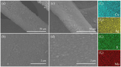
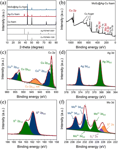
The morphologies of Ag–Cu foam and MoS2@Ag–Cu foam were examined via SEM analysis, as illustrated in Fig. 1. As observed, the Cu foam frame was coated with a layer of Ag nanoparticles (Fig. 1a and b), while still maintaining its initial hierarchical porous structure (Fig. S1a†) after the wetting chemical deposition process. As depicted in Fig. 1c, the skeletons of the Cu foam are uniformly coated with composite catalysts. A higher-magnification SEM image (Fig. 1d) revealed that the diameter of nanoparticles located on Cu foam increased following molybdenum sulfide coating. Furthermore, the corresponding elemental mapping images shown that Mo, S, and Ag elements were uniformly spatially distributed on the Cu foam (Fig. 1f1–4), which suggested that the MoS2@Ag–Cu foam composite electrode can be synthesized through the two-step procedure. For comparison, MoS2@Cu foam were prepared by similar method, as shown in the Fig. S1b and c.†The composition and structure of the synthesized electrodes were also characterized using X-ray diffraction technique, as illustrated in Fig. 2a. The peaks observed at 43.3°, 50.4° and 74.1° can be attributed to (111), (200) and (220) crystallographic planes of copper, respectively, as indicated by JCPDS card no. 85-1326. The peaks identified at 38.1°, 44.3°, 64.4°, 77.4°, and 81.5° were due to (111), (200), (220), (311) and (222) planes of Ag, respectively (JCPDS card no. 87-0597). The diffraction peaks of MoS2 were not obviously sharp due to the amorphous nature of the as-prepared molybdenum sulfide.36 It should be noted that the diffraction peak of MoS2@Ag–Cu foam electrode was significantly attenuated compared to that of Ag–Cu foam electrode, which can be attributed to the amorphous molybdenum sulfide coating covering the diffraction signal of copper and silver.
The chemical states of elements in MoS2@Ag–Cu foam was analyzed in detail by XPS, as depicted in Fig. 2b–f. The XPS survey spectra revealed the presence of major elements including Cu, Ag, S, and Mo (Fig. 2b). In Fig. 2c, two prominent peaks observed at 952.5 eV and 932.8 eV corresponded to Cu 2p1/2 and Cu 2p3/2 orbitals of Cu, respectively. The peaks at 954.4 eV and 934.4 eV were ascribed to Cu2+ 2p1/2 and Cu2+ 2p3/2 of CuO, respectively, which resulted from its oxidation in the air.37 The peaks observed at 374.4 eV and 368.3 eV can be attributed to the Ag 3d3/2 and Ag 3d5/2 orbitals of silver, respectively, as depicted in Fig. 2d. Meanwhile, the peaks at 163.0 eV and 161.8 eV are assigned to the S2− 2p1/2 and S2− 2 p3/2 orbitals of sulfide, respectively (Fig. 2e). In Fig. 2f, the Mo4+ 3d3/2 and Mo4+ 3d5/2 peaks were detected at 231.6 eV and 228.8 eV, respectively. The peaks located at 235.0 eV and 232.1 eV were attributed to Mo6+ 3d3/2 and Mo6+ 3d5/2, respectively, because of the reoxidation process of MoS2. Additionally, two peaks appearing at 226.6 eV and 225.9 eV can be assigned to S22− 2s and S2− 2s orbitals of amorphous MoS2.36 The SEM, XRD and XPS analyses provided comprehensive evidence that the Cu foam substrate was effectively coated with a bilayer of silver nanoparticles and molybdenum sulfide.
Optical property
The rate of photoinduced carrier recombination is a crucial factor that impacts the photoelectrocatalytic performance, which can be evaluated through photoluminescence (PL) emission spectra analysis. Fig. 3a displayed the normalized PL emission spectra of the samples obtained, such as pure Cu foam, Ag–Cu foam, MoS2@Cu foam, and MoS2@Ag–Cu foam, through fluorescence spectroscopy with an excitation wavelength of 410 nm. Evidently, Cu foam and Ag–Cu foam, without MoS2 layer, exhibited the most prominent diffraction signal at 600 nm, indicating that it can generate a significant number of photogenerated carriers originated from the plasmon resonance effect of copper and undergoes rapid recombination.8,15 Significantly weaker emission signals were observed from MoS2@Ag–Cu foam and MoS2@Cu foam, both with a layer of MoS2, compared to those from Cu foam and Ag–Cu foam. This suggested that the presence of MoS2 can effectively trap hot carriers and hinder their recombination. The UV-vis absorption spectra of the obtained samples was analyzed, as illustrated in Fig. 3b. The absorption peak at 580 nm observed in the pristine Cu foam electrode was attributed to the surface plasmon resonance (SPR) absorption of copper.38 In comparison with Cu foam, the additional absorption in Ag–Cu foam at wavelength shorter than 350 nm was ascribed to the SPR absorption of silver.39 More importantly, the light absorption for MoS2@Ag–Cu foam was significantly extended to visible absorption region due to the narrow band gap of MoS2.40,41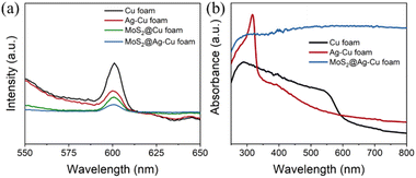 | ||
| Fig. 3 (a) Photoluminescence spectra, and (b) UV-visible absorption spectra of Cu foam, Ag–Cu foam, and MoS2@Ag–Cu foam. | ||
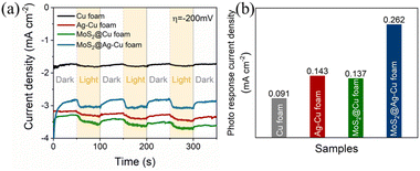
To demonstrate the effective photoelectrocatalytic properties facilitated by the SPR effect and molybdenum sulfide enhancement, we conducted a comparative analysis of the photo response current density for the obtained samples. As illustrated in Fig. 4a, the photocurrent chronoamperometry was performed with chopped light irradiation at potential of −200 mV. The photoresponsivity of Cu foam was evident, while that of Ag–Cu foam electrode exhibited even higher enhancement, and their photo response current densities were 0.091 and 0.143 mA cm−2, respectively. After applying a molybdenum sulfide trap, the photo response current density of MoS2@Ag–Cu foam electrode increased twofold compared to that of Ag–Cu foam, as illustrated in Fig. 4b. On the contrary, MoS2/FTO electrode, in the absence of plasmonic metal, exhibited a negligible photo response current density under identical conditions (Fig. S2†).
The stability of the electrode
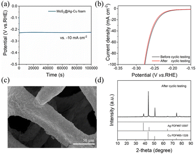
The superior stability of MoS2@Ag–Cu foam composite electrode was confirmed via electrochemical and physical techniques. As shown in Fig. 5a, the composite electrode exhibited exceptional potential stability over 28 hours at 10 mA cm−2. Fig. 5b showed that the LSV curve after cyclic testing exhibited a negligible decline compared to the pristine curve. The SEM image (Fig. 5c), XRD pattern (Fig. 5d), and EDS mapping images (Fig. S3†) of MoS2@Ag–Cu foam after long-term cyclic testing indicated structural and morphological stability.Mechanism analysis
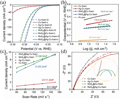
The electrochemical measurements were analyzed to elucidate the mechanism underlying the enhancement of photoelectrocatalytic hydrogen evolution. The electrochemical activity measurements of MoS2@Ag–Cu foam for HER in 0.5 M H2SO4 solution were carried out using a typical three-electrode cell setup in the dark and under illumination, as depicted in Fig. 6a. For comparison, the HER activities of bare Cu foam, Ag–Cu foam, and MoS2@Cu foam were investigated. The LSV curves of the composite electrodes exhibited improved HER performance under illuminated conditions compared to those observed in the absence of light. And the composite electrodes coated with molybdenum sulfide indicated enhanced electrocatalytic activity towards HER. The MoS2@Ag–Cu foam electrode exhibited an overpotential of 218 mV at current density of 10 mA cm−2, surpassing those of bare Cu foam, Ag–Cu foam, and MoS2@Cu foam, whether in the dark or under illumination. The specific overpotential values at 10 mA cm−2 and 50 mA cm−2 under illumination were presented in Table S1.†The Tafel slope, obtained from the LSV curves of prepared electrodes, serves as an indicator of the intrinsic catalytic activity. As is shown in Fig. 6b, the Tafel slope of MoS2@Ag–Cu foam (54.2 mV dec−1) was comparable to that of MoS2@Cu foam (68.5 mV dec−1), yet significantly lower than that of Ag–Cu foam (115 mV dec−1) and pure Cu foam (153 mV dec−1). This suggested that the outer layer of molybdenum sulfide can serve as an electron mediator between plasmonic meatal and H+ in aqueous solution, stimulating rapid kinetics for HER.
The enhanced photoelectrocatalytic performance of MoS2@Ag–Cu foam was also attributed to its higher electrochemically active surface area (ECSA). The estimation of the ECSA at the solid–liquid interface can be achieved through the measurement of electrochemical double-layer capacitance (EDLC) via CV test.42 The EDLC values were determined by calculating the slope of the linear regression analysis of the capacitive current plotted against scan rate (Fig. S4†). As shown in Fig. 6c, the EDLC value of MoS2@Ag–Cu foam (53.2 mF cm−2) was ∼1.4 times than that of MoS2@Cu foam (38.5 mF cm−2), ∼4.8 times than that of Ag–Cu foam (11.2 mF cm−2) and ∼30 times than that of Cu foam (1.8 mF cm−2). This indicated that the MoS2@Ag–Cu foam composite electrode possessed the highest ECSA. The values of Tafel slop and ECSA were exhibited in Table S1.†
The Nyquist plot was generated through EIS analysis to evaluate the surface kinetics of the electrodes prepared, as illustrated in Fig. 6d. The diameter of the fitted semicircle represented the charge transfer resistance (Rct), which denotes the resistance encountered during electron transport. The Nyquist plots of the electrodes with layer of molybdenum sulfide (MoS2@Ag–Cu foam and MoS2@Cu foam) exhibited a narrower semicircle diameter than that of the other electrodes. The as prepared electrodes displayed the smaller Rct values under illumination, especially for electrode with silver nano-layer.
As illustrated in Scheme 2a, upon exposure to resonant optical radiation, the plasmonic metal exhibited oscillation of its free electrons within the conductive band. Then the hot electron–hole pairs were generated via non-radiation attenuated Landau damping within a time frame of 1 to 100 fs.44 The plasmon-induced electric field promotes the transition of electrons from occupied states to the higher energy SPR states.45,46 Unfortunately, the photoelectrocatalytic performance of pure plasmonic metals is severely limited by their high recombination probability for photogenerated carriers (shown in Fig. 3a) and sluggish kinetics for HER (shown in Fig. 6). For MoS2@Ag–Cu hybrids catalyst, on the one hand, silver and copper metals produced a huge number of hot electrons through the SPR effect. On the other hand, the band structure of molybdenum sulfide has been engineered to enable efficient capture and utilization of photoelectrons generated from the SPR effect for stimulating HER reaction, as depicted in Scheme 2b.
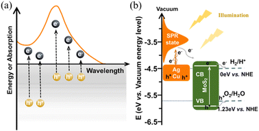 | ||
| Scheme 2 The schematic illustration of (a) hot carriers generation and the corresponding absorption spectrum of plasmonic metals,34 and (b) the energy band alignment for charge transfer in MoS2@Ag–Cu hybrids catalyst.38,43 | ||
Conclusions
In conclusion, the self-supported MoS2@Ag–Cu foam electrode was successfully fabricated as a photocathode through a two-step procedure. The enhanced performance of the MoS2@Ag–Cu foam photocathode originated from surface plasmon resonance (SPR) effect of silver and copper, which served as primary optical absorbers. Molybdenum sulfide acted as a hot electron trap, enhancing the separation efficiency of photogenerated carriers and expediting rapid kinetics, to promote hydrogen evolution reaction. Besides, the superior stability of composite electrode is ascribed to the in situ growth method employed for its preparation. The development of low-cost plasmonic metal-based materials, the next generation photocatalysts, is key to breaking through the bottleneck of photoelectrocatalytic performance improvement.Author contributions
Yuanyuan Tian: conceptualization, methodology, supervision, investigation, funding acquisition, writing-original draft, and writing-review & editing. Chengnan Qi: investigation, formal analysis, data curation, and writing-original draft. Ruihua Zhou, Dan Li: methodology and resources. Tao Han: resources, project administration, and supervision.Conflicts of interest
There are no conflicts to declare.Acknowledgements
This study has been financially supported by Scientific and Technological Innovation Programs of Higher Education Institutions in Shanxi (Grant No. 2021L606), Fundamental Research Program of Shanxi Province (Grant No. 202203021222328) and Research Initiation Fund Programs of Shanxi College of Technology (Grant No. 200101).References
- X. Li, G. Wang, L. Jing, W. Ni, H. Yan, C. Chen and Y. M. Yan, A photoelectrochemical methanol fuel cell based on aligned TiO2 nanorods decorated graphene photoanode, Chem. Commun., 2016, 52, 2533–2536 RSC.
- B. O'Regan and M. Graetzel, A low-cost, high-efficiency solar cell based on dye-sensitized colloidal TiO2 films, Nature, 1991, 353, 737–740 CrossRef.
- B. Cao, G. Li and H. Li, Hollow spherical RuO2@TiO2@Pt bifunctional photocatalyst for coupled H2 production and pollutant degradation, Appl. Catal., B, 2016, 194, 42–49 CrossRef CAS.
- H.-F. Ye, R. Shi, X. Yang, W.-F. Fu and Y. Chen, P-doped ZnxCd1−xS solid solutions as photocatalysts for hydrogen evolution from water splitting coupled with photocatalytic oxidation of 5-hydroxymethylfurfural, Appl. Catal., B, 2018, 233, 70–79 CrossRef CAS.
- Y. Cong, Y. Ge, T. Zhang, Q. Wang, M. Shao and Y. Zhang, Fabrication of Z-Scheme Fe2O3–MoS2–Cu2O ternary nanofilm with significantly enhanced photoelectrocatalytic performance, Ind. Eng. Chem. Res., 2018, 57, 881–890 CrossRef CAS.
- X. Zhang, Y. Wang, B. Liu, Y. Sang and H. Liu, Heterostructures construction on TiO2 nanobelts: a powerful tool for building high-performance photocatalysts, Appl. Catal., B, 2017, 202, 620–641 CrossRef CAS.
- L. Wu, X. Yang, J. Li, Y. Huang and X. Li, Fabrication of titanium dioxide nanotubes with good morphology at high calcination temperature and their photocatalytic activity, Mater. Chem. Phys., 2017, 202, 136–142 CrossRef CAS.
- C. Mahala, M. D. Sharma and M. Basu, ZnO nanosheets decorated with graphite-like carbon nitride quantum dots as photoanodes in photoelectrochemical water splitting, ACS Appl. Nano Mater., 2020, 3, 1999–2007 CrossRef CAS.
- K. Xie, Z. Wu, M. Wang, J. Yu, C. Gong, L. Sun and C. Lin, Room temperature synthesis of CdS nanoparticle-decorated TiO2 nanotube arrays by electrodeposition with improved visible-light photoelectrochemical properties, Electrochem. Commun., 2016, 63, 56–59 CrossRef CAS.
- J. Li and N. Wu, Semiconductor-based photocatalysts and photoelectrochemical cells for solar fuel generation: a review, Catal. Sci. Technol., 2015, 5, 1360–1384 RSC.
- X. Gong, Z. Jiang, W. Zeng, C. Hu, X. Luo, W. Lei and C. Yuan, Alternating magnetic field induced magnetic heating in ferromagnetic cobalt single-atom catalysts for efficient oxygen evolution reaction, Nano Lett., 2022, 22, 9411–9417 CrossRef CAS PubMed.
- P. Lianos, Review of recent trends in photoelectrocatalytic conversion of solar energy to electricity and hydrogen, Appl. Catal., B, 2017, 210, 235–254 CrossRef CAS.
- M. Wang, Y. Yang, J. Shen, J. Jiang and L. Sun, Visible-light-absorbing semiconductor/molecular catalyst hybrid photoelectrodes for H2 or O2 evolution: recent advances and challenges, Sustainable Energy Fuels, 2017, 1, 1641–1663 RSC.
- X. Li, S. Guo, C. Kan, J. Zhu, T. Tong, S. Ke, W. C. H. Choy and B. Wei, Au multimer@MoS2 hybrid structures for efficient photocatalytical hydrogen production via strongly plasmonic coupling effect, Nano Energy, 2016, 30, 549–558 CrossRef CAS.
- Q. Liu, Y. Wei, M. Z. Shahid, M. Yao, B. Xu, G. Liu, K. Jiang and C. Li, Spectrum-enhanced Au@ZnO plasmonic nanoparticles for boosting dye-sensitized solar cell performance, J. Power Sources, 2018, 380, 142–148 CrossRef CAS.
- H. Wang, Y. Gao, J. Liu, X. Li, M. Ji, E. Zhang, X. Cheng, M. Xu, J. Liu, H. Rong, W. Chen, F. Fan, C. Li and J. Zhang, Efficient plasmonic Au/CdSe nanodumbbell for photoelectrochemical hydrogen generation beyond visible region, Adv. Energy Mater., 2019, 9, 1803889–1803898 CrossRef.
- F. Qi, C. Wang, N. Cheng, P. Liu, Y. Xiao, F. Li, X. Sun, W. Liu, S. Guo and X.-Z. Zhao, Improving the performance through SPR effect by employing Au@SiO2 core-shell nanoparticles incorporated TiO2 scaffold in efficient hole transport material free perovskite solar cells, Electrochim. Acta, 2018, 282, 10–15 CrossRef CAS.
- X. Yu, J. Bi, G. Yang, H. Tao and S. Yang, Synergistic effect induced high photothermal performance of Au Nanorod@Cu7S4 yolk–shell nanooctahedron particles, J. Phys. Chem. C, 2016, 120, 24533–24541 CrossRef CAS.
- C. Wang, X.-P. Zhao, Q.-Y. Xu, X.-G. Nie, M. R. Younis, W.-Y. Liu and X.-H. Xia, Importance of hot spots in gold nanostructures on direct plasmon-enhanced electrochemistry, ACS Appl. Nano Mater., 2018, 1, 5805–5811 CrossRef CAS.
- C. Boerigter, U. Aslam and S. Linic, Mechanism of charge transfer from plasmonic nanostructures to chemically attached materials, ACS Nano, 2016, 10, 6108–6115 CrossRef CAS PubMed.
- C. Boerigter, R. Campana, M. Morabito and S. Linic, Evidence and implications of direct charge excitation as the dominant mechanism in plasmon-mediated photocatalysis, Nat. Commun., 2016, 7, 10545 CrossRef CAS PubMed.
- J. Qiu and W. D. Wei, Surface plasmon-mediated photothermal chemistry, J. Phys. Chem. C, 2014, 118, 20735–20749 CrossRef CAS.
- L. Liu, X. Zhang, L. Yang, L. Ren, D. Wang and J. Ye, Metal nanoparticles induced photocatalysis, Natl. Sci. Rev., 2017, 4, 761–780 CrossRef CAS.
- Z. Hu, G. Liu, X. Chen, Z. Shen and J. C. Yu, Enhancing charge separation in metallic photocatalysts: a case study of the conducting molybdenum dioxide, Adv. Funct. Mater., 2016, 26, 4445–4455 CrossRef.
- X. Xu, C. Randorn, P. Efstathiou and J. T. Irvine, A red metallic oxide photocatalyst, Nat. Mater., 2012, 11, 595–598 CrossRef CAS PubMed.
- D. Ko, X. Jin, K.-d. Seong, B. Yan, H. Chai, J. M. Kim, M. Hwang, J. Choi, W. Zhang and Y. Piao, Few-layered MoS2 vertically aligned on 3D interconnected porous carbon nanosheets for hydrogen evolution, Appl. Catal., B, 2019, 248, 357–365 CrossRef CAS.
- Z. Jiang, C. Hu, X. Luo, X. Gong, W. Zeng, C. Zou, H. Zhou, W. Zhou, T. Yu, W. Lei and C. Yuan, Alternating magnetic field improved NiFe@MoS2 monolayer diatomic site catalyst for overall water splitting, Appl. Phys. Lett., 2023, 122, 073901 CrossRef CAS.
- M. Su, W. Zhou, L. Liu, M. Chen, Z. Jiang, X. Luo, Y. Yang, T. Yu, W. Lei and C. Yuan, Micro eddy current facilitated by screwed MoS2 structure for enhanced hydrogen evolution reaction, Adv. Funct. Mater., 2022, 32, 2111067 CrossRef CAS.
- X. Yan, G. Wang, Y. Zhang, Q. Guo and Z. Jin, 3D layered nano-flower MoSx anchored with CoP nanoparticles form double proton adsorption site for enhanced photocatalytic hydrogen evolution under visible light driven, Int. J. Hydrogen Energy, 2020, 45, 2578–2592 CrossRef CAS.
- S. Zhang, H. Yang, H. Gao, R. Cao, J. Huang and X. Xu, One-pot synthesis of cds irregular nanospheres hybridized with oxygen-incorporated defect-rich MoS2 ultrathin nanosheets for efficient photocatalytic hydrogen evolution, ACS Appl. Mater. Interfaces, 2017, 9, 23635–23646 CrossRef CAS PubMed.
- Z. Jiang, W. Zhou, A. Hong, M. Guo, X. Luo and C. Yuan, MoS2 moiré superlattice for hydrogen evolution reaction, ACS Energy Lett., 2019, 4, 2830–2835 CrossRef CAS.
- X. Xu, J. Hu, Z. Yin and C. Xu, Photoanode current of large-area MoS2 ultrathin nanosheets with vertically mesh-shaped structure on indium tin oxide, ACS Appl. Mater. Interfaces, 2014, 6, 5983–5987 CrossRef CAS PubMed.
- W. Zeng, Z. Jiang, X. Gong, C. Hu, X. Luo, W. Lei and C. Yuan, Atomic magnetic heating effect enhanced hydrogen evolution reaction of Gd@MoS2 single-atom catalysts, Small, 2022, 19, 2206155 CrossRef PubMed.
- Y. Zhang, S. He, W. Guo, Y. Hu, J. Huang, J. R. Mulcahy and W. D. Wei, Surface-plasmon-driven hot electron photochemistry, Chem. Rev., 2018, 118, 2927–2954 CrossRef CAS PubMed.
- Y. Tian, Y. Song, M. Dou, J. Ji and F. Wang, Enhanced photo-assistant electrocatalysis of anodization TiO2 nanotubes via surrounded surface decoration with MoS2 for hydrogen evolution reaction, Appl. Surf. Sci., 2018, 433, 197–205 CrossRef CAS.
- J. Tan, W. Yang, Y. Oh, H. Lee, J. Park and J. Moon, Controlled electrodeposition of photoelectrochemically active amorphous MoSX cocatalyst on Sb2Se3 photocathode, ACS Appl. Mater. Interfaces, 2018, 10, 10898–10908 CrossRef CAS PubMed.
- Y. Xu, C. Li, Y. Xiao, C. Wu, Y. Li, Y. Li, J. Han, Q. Liu and J. He, Tuning the selectivity of liquid products of CO2RR by Cu-Ag alloying, ACS Appl. Mater. Interfaces, 2022, 14, 11567–11574 CrossRef CAS PubMed.
- Y. Tian, Y. Song, J. Liu, J. Ji and F. Wang, MoSx coated copper nanowire on copper foam as a highly stable photoelectrode for enhanced photoelectrocatalytic hydrogen evolution reaction via. plasmon-induced hot carriers, Chem. Eng. J., 2020, 398, 125554 CrossRef CAS.
- S. Linic, P. Christopher and D. B. Ingram, Plasmonic-metal nanostructures for efficient conversion of solar to chemical energy, Nat. Mater., 2011, 10, 911–921 CrossRef CAS PubMed.
- Z. Zhang, H. Liu, J. Zhang, F. Wang, Y. Xie, X. Shang, Y. Gu, H. Zhao and X. Wang, In situ constructing interfacial contact MoS2/ZnIn2S4 heterostructure for enhancing solar photocatalytic hydrogen evolution, Appl. Catal., B, 2018, 233, 112–119 CrossRef CAS.
- S. A. Darsara, M. Seifi and M. B. J. O. Askari, One-step hydrothermal synthesis of MoS2/CdS nanocomposite and study of structural, photocatalytic, and optical properties of this nanocomposite, Optik, 2018, 169, 249–256 CrossRef CAS.
- Z. Zhang, S. Ye, J. Ji, Z. Li and F. Wang, Core/shell-structured NiMoO4@MoSe2/NixSey nanorod on Ni foam as a bifunctional electrocatalyst for efficient overall water splitting, Colloids Surf., A, 2020, 599, 124888 CrossRef CAS.
- N. Zhang, M. Li, C. F. Tan, C. K. Nuo Peh, T. C. Sum and G. W. Ho, Plasmonic enhanced photoelectrochemical and photocatalytic performances of 1D coaxial Ag@Ag2S hybrids, J. Mater. Chem. A, 2017, 5, 21570–21578 RSC.
- T. V. Shahbazyan, Landau damping of surface plasmons in metal nanostructures, Phys. Rev. B, 2016, 94, 235431–235440 CrossRef.
- F. Hao, Y. Sonnefraud, P. V. Dorpe, S. A. Maier, N. J. Halas and P. Nordlander, Symmetry breaking in plasmonic nanocavities: subradiant LSPR sensing and a tunable Fano resonance, Nano Lett., 2008, 8, 3983 CrossRef CAS PubMed.
- S. D. Forno, L. Ranno and J. Lischner, Material, size, and environment dependence of plasmon-induced hot carriers in metallic nanoparticles, J. Phys. Chem. C, 2018, 122, 8517–8527 CrossRef.
Footnote |
| † Electronic supplementary information (ESI) available. See DOI: https://doi.org/10.1039/d3ra04357f |
| This journal is © The Royal Society of Chemistry 2023 |


