
 Open Access Article
 This Open Access Article is licensed under a Creative Commons Attribution-Non Commercial 3.0 Unported Licence
Oil-gated isoporous membrane with micro-apertures for controllable pressure-induced passive flow regulator†
Yujin Parka,
Joondong Kim b,
Ju-Hyung Yunb,
Segeun Jang*c and
Sang Moon Kim*a
b,
Ju-Hyung Yunb,
Segeun Jang*c and
Sang Moon Kim*a
aDepartment of Mechanical Engineering, Incheon National University, Incheon, 22012, Republic of Korea. E-mail: ksm7852@inu.ac.kr
bDepartment of Electrical Engineering, Incheon National University, Incheon, 22012, Republic of Korea
cSchool of Mechanical Engineering, Kookmin University, Seoul 02707, Republic of Korea. E-mail: sjang@kookmin.ac.kr
First published on 10th July 2023
Abstract
The pressure-driven liquid flow controller is one of the key components in diverse applications including microfluidic systems, biomedical drug injection devices, and pressurized water supply systems. Electric feedback loop based flow controllers are fine-tunable but expensive and complex. The conventional safety valves based on spring force are simple and low cost, but their diverse application is limited due to their fixed pressure range, size, and shape. Herein, we propose a simple and controllable liquid-flowing system combining a closed liquid reservoir and an oil-gated isoporous membrane (OGIM). The ultra-thin and flexible OGIM acts as an immediately responsive and precisely controlled gas valve to maintain internal pneumatic pressure as designed to induce constant liquid flow. The oil filling apertures act as a gate for gas flow depending on the applied pressure and the threshold (gating) pressure of the gate is determined by the surface tension of the oil and the gate diameter. It is confirmed that the gating pressure is precisely controlled by varying the gate diameter, which agrees with the theoretically estimated pressures. Based on stably maintained pressure due to the function of OGIM, the constant liquid flow rate is achieved even with the high gas flow rate.
1. Introduction
In pressure-driven liquid flow systems such as microfluidics systems, biomedical drug injection devices, and pressurized water supply systems, the liquid flow rate is proportional to the applied gas pressure to the liquid in the channel.1–4 In these systems, controlling and maintaining accurate pneumatic pressure is key to flowing the liquid in the channel constantly and stably at the designed flow rate. However, huge pressure fluctuation and/or overpressure due to failure of fine controlling the designed pressure would induce a high flow rate over the set value. It may cause severe damage including destroying the pipeline or the microfluidic systems, and hindering the delivery of an accurate amount of drug to the human body.3,4 To avoid failures by controlling the flow rate constantly and stably, proportional–integral–derivative (PID) controllers have been widely used in various ways.5,6 A microdroplet device-controlled PID system utilizes a compressed gas supplier, liquid reservoir, proportional valve, and pressure sensor to achieve precise control. The inlet pressure in the microchannel serves as the set value in the feedback loop. Compressed gas passes through the valve, applying pneumatic pressure to the liquid in the reservoir, leading to the liquid flow. If the measured pressure at the inlet deviates from the set pressure, the proportional valve is adjusted automatically via a PID control mechanism. This enables the desired liquid flow rate based on a proportional relationship between flow rate and microchannel inlet pressure.5 While PID controllers offer advantages such as quick response time and high accuracy, they are expensive and require complex systems, limiting their application. Alternatively, self-actuating safety valves utilizing spring force maintain stable internal pressure in pressurized water supply systems. If the pneumatic pressure exceeds the set pressure, the spring compresses, opening the valve to release the excess pressure.7 This design ensures system stability even during power cut-off and is cost-effective compared to PID controllers. However, due to their fixed shapes, sizes, and pressure ranges, these valves limit direct applicability and require adequate installation space. And sophisticated computational fluid dynamics-based modeling is required to predict accurate fluid flow and adequately design the channel.8Recently, unlike rigid and complex conventional systems, flow-rate regulators using soft and flexible components have been extensively studied with diversely devised designs.9–13 These regulators utilize the inlet pressure as a driving force to adjust the fluidic resistance of microchannels automatically. One example is the introduction of a passive flow-rate regulator utilizing a parallel membrane valve. In this design, a gap comprising two parallel membranes acts as a passive valve. As the inlet pressure increases, the fluidic resistance of the gap also increases from the membrane valve deflection, enabling the maintenance of a desired flow rate. However, these types of regulators require relatively high critical pressure (Pc) because constant flow relies on the deformation or deflection of the valves. The relationship between pressure and structural deformation is not linear, and precisely regulating flow rate is challenging since the membrane deformation varies depending on the structural shape and length of the membrane. Moreover, microchannels can be clogged easily unless the channels are regularly cleaned. As another type of soft valve, a dome-shaped elastomeric membrane was proposed recently.14 The dome-shaped membrane acts as a switch by snapping the membrane upward or downward depending on the pneumatic pressure. It enables control of the flow rate at a desired time. However, it is an active-type valve that needs an additional pressure controller, and relatively huge flow rate fluctuation occurs at the opening and closing of the channel. Also, it is challenging to exactly match the critical pressure to the structure shape and thickness. The advantages and limitation of each method are summarized in Table S1.† To address the issues of cost, applicability, and complexity of conventional devices, we propose a passive-type controllable system that can supply liquid with a desired flow rate consistently without electrical power and complicated components. Herein, we adopted the concept of an oil-gated membrane (OGM), which has already proven to have anti-contamination characteristics, critical pressure adjustability, and the possibility of separation of gas/liquid phases.15–20 The membrane pores filled with the capillary-stabilized oil (gating oil) reversibly open and close depending on the difference between the applied pressure and the critical pressure for gas of OGM. If applied pressure exceeds the Pc, the pores open and if the pressure is below the Pc, the pores immediately close. When this OGM has connected to a liquid flowing system, the internal pressure of the system can be kept constant at the designed value even when the internal pressure increases by the continuous gas injection, in turn, inducing a driving force to make a constant water flow rate. It enables the avoidance of corrosion issues and the OGM can be easily replaced for the realization of the designed liquid flow rate based on the fact that the Pc of OGM can be adjusted simply by differing the membrane pore sizes and the surface tension of the gating oil. Furthermore, it is possible to design water-flowing systems more compact and flexible in various ways according to their desired purpose.
Even though OGM has many advantages, it is necessary to fabricate and apply membranes with uniform arrayed apertures, which is an isoporous membrane for the realization of precise control of Pc. However, the traditional fabrication processes have a limitation in precisely manufacturing an isoporous membrane. The fiber-based fabrication process generates randomly distributed aperture sizes. Although laser-perforation methods are being used to make an isoporous membrane,16,21 it is expensive and time-consuming to make a large-scale OGM based on the fact that the perforation process using laser can generate one aperture at once. To deal with those issues, we manufacture polymeric membranes with an isoporous micro-sized aperture array through a simple and facile one-step UV-curing process and construct an oil-gated isoporous membrane (OGIM) by coating specific oil onto the membrane. By using a soft-lithographic method, membranes with isoporous and various pore sizes/thicknesses can be made easily at a low cost in a short time.22,23 Since the membrane is ultra-thin (<120 μm in this study) and flexible, it is space-efficient and easy to integrate even into the curved system, which paves the way for customization of the design, size, and construction of the water-flowing systems. To show the advantages and usefulness of the OGIM based water flowing system, fine-tuned liquid flow systems with OGIM have been demonstrated in this study. The delicate tunability of Pc for gas of isoporous membranes with various pore sizes and gating liquids was confirmed both theoretically and experimentally. Also, the adjustability of the water flow rate depending on the aperture size of the OGIM has been proved and the experimentally obtained flow rates were in good agreement with the estimated theoretical values. Besides, its function as a water flow rate buffer was verified through the rapid change in the applied pressure.
2. Experimental section
2.1. Fabrication of the micro-pillar patterned PDMS molds
In order to fabricate micro-pillar patterned polymethylsiloxane (PDMS; Dow Corning, United States) molds, a hole patterned silicon master is prepared. The silicon master with holes is made by photo-lithography and reactive ion etching (RIE), and subsequently, the surface is treated with C4F8 gas for easy detachment of the PDMS molds. After preparing the PDMS mixture by mixing Sylgard 184 and the curing agent with a weight ratio of 10![[thin space (1/6-em)]](https://www.rsc.org/images/entities/char_2009.gif) :1, the PDMS mixture was poured onto the silicon master and cured in an oven at 70 °C for about 2 hours.24–26
:1, the PDMS mixture was poured onto the silicon master and cured in an oven at 70 °C for about 2 hours.24–26
2.2. Fabrication of the PUA stencils
After detaching the PDMS stamp, UV curable resin (MINS-311RM; Changsung Sheet, Korea) was dispensed onto the patterned PDMS mold and covered with a bare PDMS. Two PDMS molds were pressured by hand slightly and cured by being exposed to UV light for about 30 seconds. Then, OGIM was prepared by dropping oil (Krytox 103 and silicone oil 1000 cSt) onto the surface of the constructed PUA stencils with various aperture sizes.2.3. Characterization
Scanning electron microscopy (SEM) images were obtained using field emission SEM (FE-SEM, JSM-7800F, JEOL, Japan) with 15.0 kV acceleration voltage. To confirm the cross-sectional shape of the apertures for each case, the constructed polymeric stencils were cut by a sharp knife and observed through SEM images.2.4. Measurement of water flow rate and differential pressure
The pressure was measured and logged using a manometer (PS-9110SD, Lutron, United States, max range ± 200 kPa, resolution 0.1 kPa, 1 s per count).3. Results and discussion
3.1. Fabrication and characterization of oil-gated isoporous membrane (OGIM)
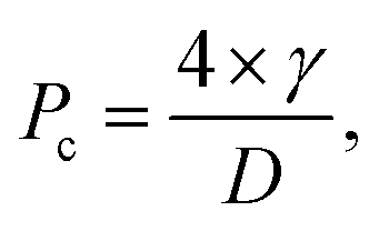
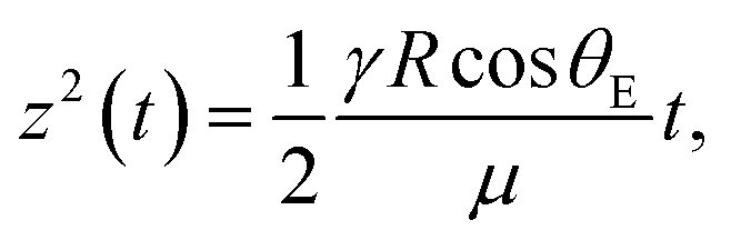
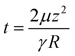
In order to fabricate the OGIM and integrate it into the pneumatic pressure-adjusted water flow rate system, two processes are required. (i) Fabrication of isoporous polymeric membrane with arrayed micro apertures (Fig. 1a). (ii) Infusing the gating oil into the fabricated membrane (Fig. 1b). In the first fabrication process, pillar-patterned polydimethylsiloxane (PDMS) molds were prepared from the hole-patterned silicon master, and the polyurethane acrylate 311 (PUA 311; MINS-311RM), which is UV-curable prepolymer, was dispensed on the patterned PDMS and was covered with a flat PDMS. After the pressure was applied by gentle finger touch (<10 kPa) to spread and squeeze out the excess prepolymer, this assembly was exposed to UV lights for 30 seconds. And the cured PUA stencil was carefully detached from the PDMS molds. In this study, the aperture diameters of the PUA stencil were designed to be 20 μm, 30 μm, 40 μm, 50 μm, and 100 μm to verify the adjustability of Pc depending on the pore size. In the geometry of the array, the spacing ratio (SR), defined as the spacing between the apertures divided by the diameter of the aperture, of all the samples is set to be one. And the open ratio, defined as the area of apertures over the entire area in a unit cell of the membrane, of all the single-layer stencils is 20%. To confirm the dimension and the shape morphology of the fabricated PUA stencil, scanning electron microscope (SEM) images were obtained (Fig. 1c and d). The morphology of the apertures of the PUA stencils corresponds well to the PDMS micro-pillars without clogging. It indicates that the experimental conditions including applied pressure, PDMS pillar dimension, and UV curing time are appropriate to achieve high fidelity between the dimension of the PDMS pillar and PUA stencil aperture without the deformation of the PDMS pillar.24,25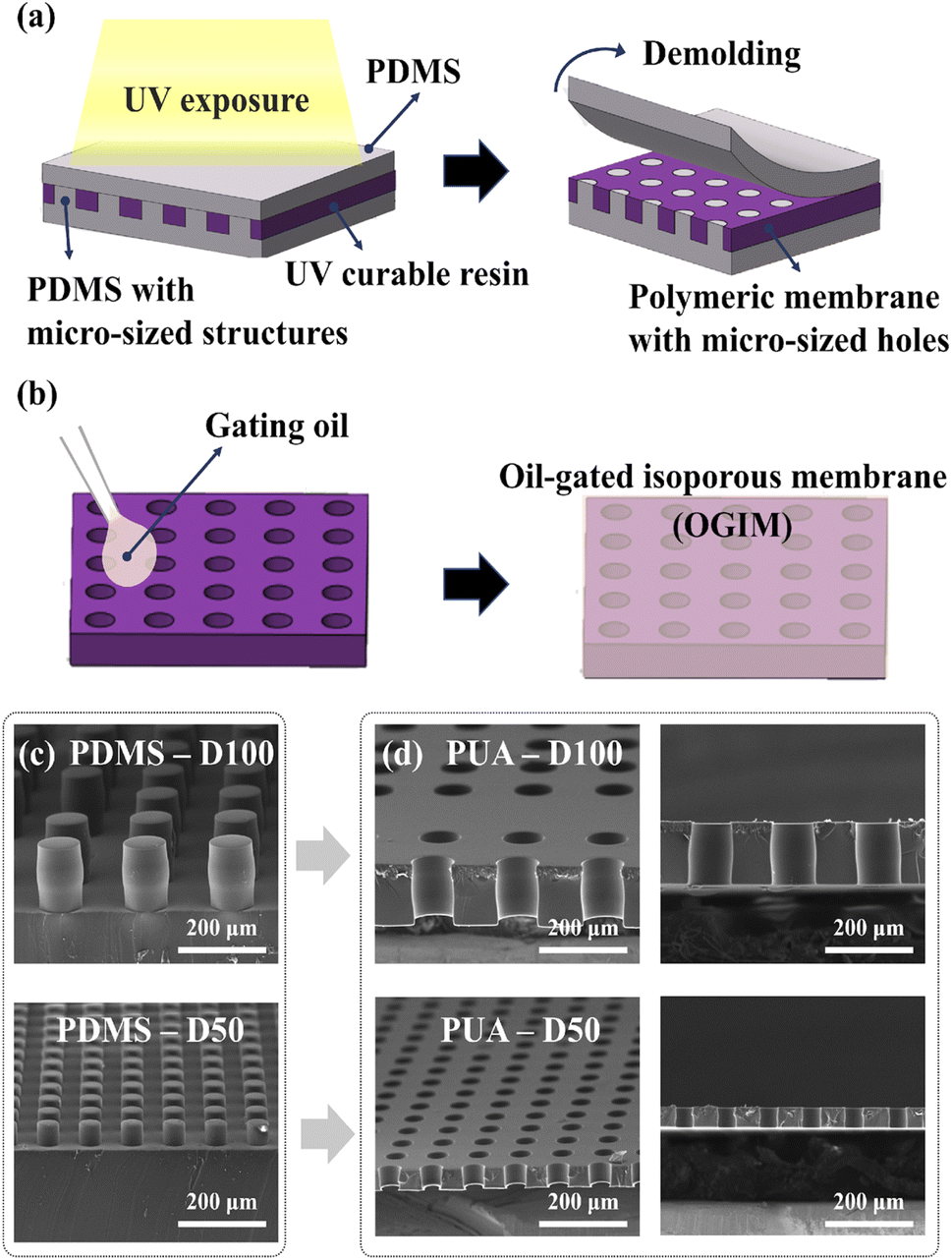 | ||
| Fig. 1 (a) Schematic illustration of a fabrication process of a polymeric membrane with a micro-sized hole array using soft-lithography. (b) Construction of oil-gated isoporous membrane (OGIM) by dropping the gating liquid on the prepared membrane. (c) The SEM images of pillar patterned PDMS mold with a diameter of 100 μm (top) and 50 μm (bottom). (d) The SEM images of PUA membranes replicated from the PDMS molds with a hole diameter of 100 μm (D100) and 50 μm (D50) in bird view and cross-sectional view. | ||
In the second process, the gating oil is filled into the apertures of well-constructed PUA stencils through the capillary-stabilized mechanism to fabricate the OGIM. Here, the pore-filling oil has to be stably sustained even when the transport fluid passes through the pores.
There are 3 requirements that must be met to construct a stable OGIM system as follows:
1. Gating oil has to be compatible with the membrane substrate.
2. The transport fluid and the gating oil should not be mutually soluble.
3. The affinity between the substrate and the gating oil should be higher than the affinity between the substrate and the transport fluid.
When the transport fluid is gas, only the wettability between the gating oil and the substrate needs to be satisfied.16,20 In this study, since OGIM was only used to emit pneumatic gas, the contact angles (CAs) of each gating oil on the flat PUA substrate were measured. The CA of Krytox 103 is 30° ± 1° and the CA of silicone oil is 10.7° ± 0.5°, both of which showed high wettability with the PUA substrate as displayed in Fig. 2a. Therefore, the tunability of Pc depending on the aperture size and the surface tension of the gating oil was confirmed by using Krytox 103 and silicone oil as a gating oil, and the PUA as a material of the membrane. After constructing the reliable OGIM system, pressure-dependent gating opening and closing of the OGIM were investigated. If the applied pressure is not sufficient to push out the pore-filling oil, oil acts as a separator of the gas at the two faces of the OGIM, whereas if the applied pressure is sufficient enough to push out the pore-filling oil, the gate opens and the apertures act as a passage for the gas. The criterion of the two cases is determined by the critical pressure, derived from the competence between the pressure-induced force on the aperture area and the surface tension force of the gating oil. The critical pressure for transporting the gas through the OGIM is expressed as below:
 | (1) |
 | (2-1) |
 | (2-2) |
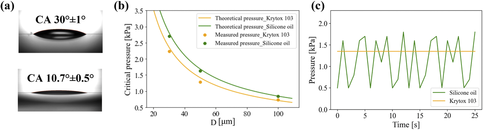 | ||
| Fig. 2 The critical pressure, which is the threshold pressure of gas through the pores of the membrane, depending on the aperture diameter and types of gating liquid. (a) Measured contact angles (CAs) of the gating oils, Krytox 103 (top) and silicone oil 1000 cSt (bottom), on the PUA substrate. (b) Plot of measured and estimated Pc at a constant gas injection flow rate of 0.1 LPM to the closed system equipped with OGIMs on the top of the system. The lines represent the theoretical Pc, and the scattered dots represent the experimentally obtained data. The green-colored data are for the OGIM with silicone oil, and the orange-colored data are for the OGIM with Krytox 103. In both cases, the Pc of the membranes with the aperture diameter of 100 μm (D100), 50 μm (D50), and 30 μm (D30) were measured. (c) Plot of system internal pressure with D50 OGIM at a constant gas injection flow rate of 0.1 LPM. The green-colored data are for the OGIM with silicone oil, and the orange-colored data are for the OGIM with Krytox 103. | ||
Based on this equation, time constants are calculated to be 1.6 ms for Krytox 103, and 9.2 ms for silicone oil. This indicates that the time required for reconfiguring silicone oil is more considerable by 6-fold compared to Krytox 103, which leads to pressure fluctuation. Even though the calculated time constant for a single aperture does not totally reflect system pressure fluctuation, it is still valid for the relative comparison of system pressure fluctuation. This inconsistency in response time can be attributed to the measuring time resolution of the manometer used in this study, which has a resolution of 1 s per count. And it is deduced that every single pore does not respond simultaneously. The accumulation effect of the single pores delays the response time of the overall system. Moreover, the opening/reconfiguration time is a function of the flow rate. Further study is needed to establish an accurate prediction model for system pressure fluctuation.
To address temperature effect on the pressure oscillation since the viscosity of an oil is temperature-dependent. Based on the data sheet provided from the supplier, temperature-dependent kinematic viscosity of the silicone oil and Krytox 103 at some specific temperature is summarized in Table S3.† Based on this, we have conducted the valving test with the OGIM with silicone oil and Krytox at high temperature as shown in Fig. S3 and Table S4.† To raise the temperature of both the injected gas and the pore-filling oil, a hot plate was placed beneath the chamber. The air temperature in the chamber was measured using a thermocouple, and the experiment was conducted when the air temperature reached 50 °C. Also, to measure the pressure of the chamber, the pressure gauge was connected to the chamber. In the case of OGIM infused with Krytox, the oscillating phenomenon was not observed in the temperature and ambient temperature and 50 °C. For the OGIM infused with silicone oil exhibited the huge pressure oscillation at ambient temperature due to the high viscosity. However, the pressure oscillation decreases noticeably at the temperature of 50 °C, since the viscosity of the silicone oil is estimated to be 600 mm2 s−1 at 50 °C, which is 40% reduced viscosity compared to that of at ambient temperature. While the limitations of our experimental setup hindered conducting experiments at higher temperatures, further investigations are necessary to examine the impact of various variables, including environmental temperature, gas flow rate, and membrane area, on pressure oscillation. In this study, Krytox 103 was selected as a gating oil for constructing OGIM for a constant water flow rate system.
3.2. Construction of water flow rate system with OGIM
In order to demonstrate the water-flowing system with a constant flow rate, we combined the water-flowing system with the OGIM system as shown in Fig. 3 and S4.† The OGIM part makes the system a semi-open state, which makes the compressive gas exit as much as the difference between the internal pressure and the Pc of the OGIM. Simultaneously, it is used to maintain internal pressure stably. The water-flowing part is where the water is ejected outside. Since it is key to controlling the water flow rate by changing only the OGIM, the water flowing part is not changed in all the cases. Commercial cellulose acetate (CA) membrane with a pore diameter of 0.45 μm was used in the water-flowing part, which does not have critical pressure. Hydrophilic property of the CA membrane, denoting a static contact angle of less than 90°, induces spontaneous filling of the water into the pores inside the membrane without an external driving force.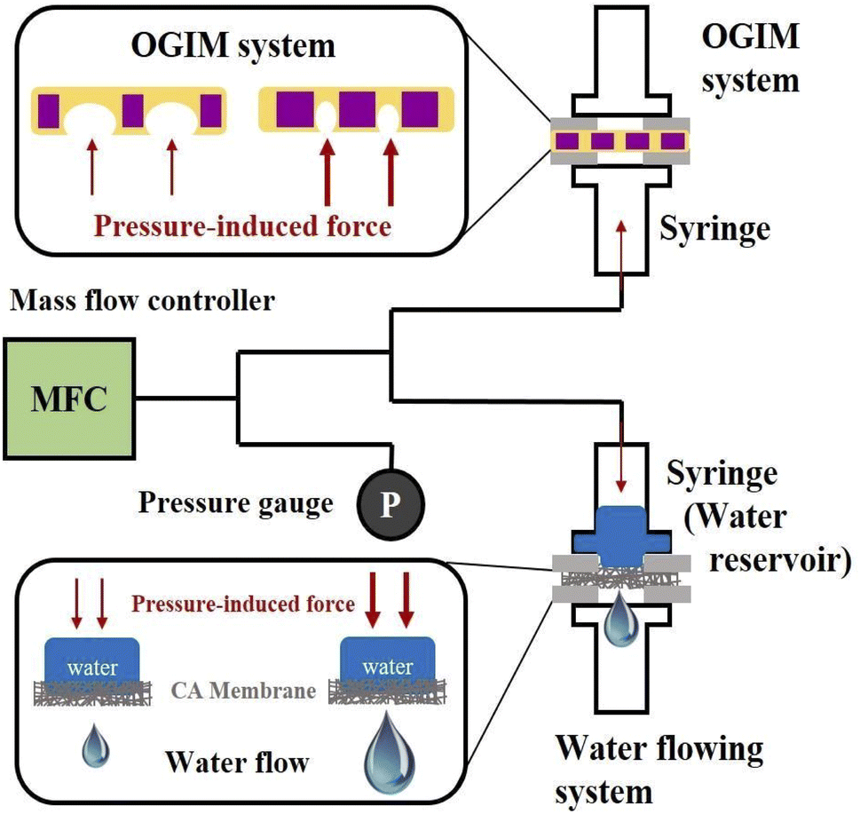 | ||
| Fig. 3 Schematic illustration of the experimental set-up. A mass flow controller (MFC) is used to inject the compressive gas into the closed system with a flow rate of 0.1 LPM. The MFC is connected to the differential pressure gauge for monitoring the internal system pressure and the OGIM/water flowing system. The OGIM releases over-pressurized gas to the outside of the system and stably maintains the internal pressure as designed. The water-flowing system releases water inside to the outlet with a specific flow rate depending on the internal pressure. | ||
Both the water-flowing part and the OGIM part have a chamber made of the syringe, and the CA membrane or the OGIM is inserted between the PDMS blocks with a hole diameter of 1 cm in the center to prevent gas and water leakage. Then, two syringes above/below the PDMS blocks with the OGIM or the CA membrane are fixed using the double-clips. MFC (Bronkhorst, max flow rate 2 LPM, resolution: 0.01 LPM) is used to give a continuous pneumatic gas to the system and it supplies the gas at flow rates of 0.1, 0.2, 0.5, 0.6, and 1.0 LPM. Due to the accumulation of continuous injected gas, the internal pressure is increasing. Manometer, a differential pressure gauge, is connected to the chamber to measure the internal pressure of the system, and the pressure data is logged per second. To measure the water flow rate, the volume of a water drop was measured, and the time taken for one water drop to fall was measured. And the flow rate was obtained by dividing the volume of a water drop by the time taken for a water drop to fall.
3.3. Demonstration of controllable liquid flow rate using OGIM
Although the simple predictability of the internal pressure and the water flow rate are the main advantages of the proposed water-flowing system, if the open area of the OGIM in which the excessive pressure of the system can alleviate is not sufficient, the unexpected increment of the internal pressure may occur. Since the amount of injected gas flow rate that the OGIM can buffer is related to the overall aperture area, it is required to investigate the capacity to release excessive gas per unit area of OGIM. Therefore, the valving capacity of the OGIM, which is the ability to release excessive gas without undesirable internal pressure increment above the Pc, was experimentally measured by varying the open ratio with the fixed overall membrane area. In order to investigate the effect of the open area on the membrane capacity, multi-layer OGIM with 4% open ratio and single-layer OGIM with 20% open ratio were prepared.31 The internal pressure was measured when using the single-layered or multi-layered OGIMs respectively while varying the injecting gas flow rate. Since the PDMS blocks with a hole diameter of 1 cm were placed below/above the OGIM, the actual open area is calculated by multiplying the PDMS hole area by each open ratio. The open area of single-layered OGIM is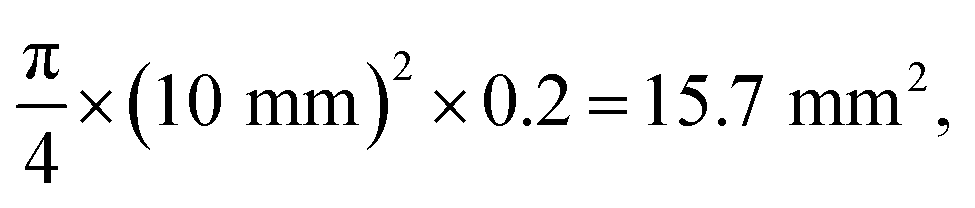 and the maximum capacity for single-layered OGIM was 0.5 LPM as shown in Fig. 4a. The open area of the multi-layered OGIM is
 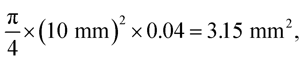 and the maximum capacity for multi-layered membrane was 0.1 LPM as shown in Fig. 4b. To calculate the valving capacity per unit open area was calculated by dividing the affordable maximum flow rate by the open area of each membrane. It is calculated to be 0.0318 LPM per mm2 for the single-layered OGIM, and 0.0317 LPM per mm2 for the multi-layered OGIM, which are comparable and indicates the valving capacity is 0.032 LPM per mm2. As for the fluidic resistance of OGIM, the resistance is defined as below:
 | (3) |
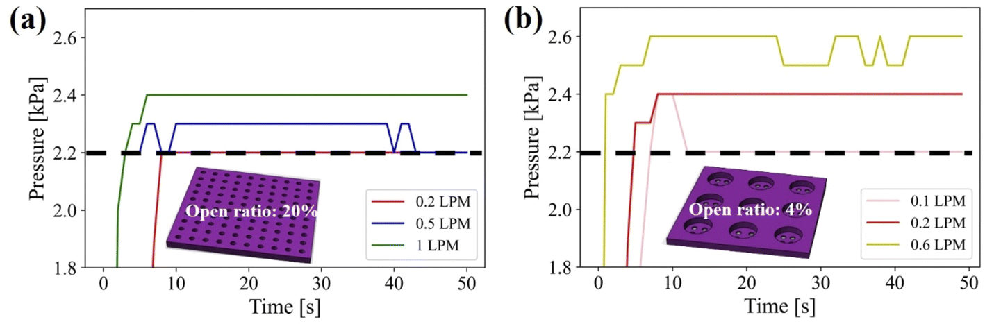 | ||
| Fig. 4 (a) The measured internal system pressure by varying gas injection flow rates with a single-layer membrane with an open ratio of 20% (open area: 15.7 mm2). (b) The measured internal system pressure by varying gas injection flow rates with a multi-layered membrane with an open ratio of 4% (open area: 3.15 mm2). | ||
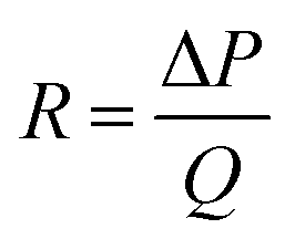
For single-layer stencil, the pressure and volume flow rate of gas is 2.2 kPa and 0.5 LPM, which resistance is 4.4 kPa per LPM (2.64 × 10⁸ Pa s m−3). And for multi-layer stencil 22 kPa per LPM (1.32 × 10⁹ Pa s m−3). And when considering the opening area of the stencil membrane for single- (3.15 mm2) and multi-layer stencil (15.7 mm2), the opening area specific resistance (R′) is defined by dividing the fluidic resistance by opening area. The area specific resistance of single- and multi-layer stencil are 1.40 × 10⁶ kPa per LPM m2 (8.38 × 10¹³ Pa s m−5) and 1.40 × 10⁶ kPa per LPM m2 (8.41 × 10¹³ Pa s m−5), which values are comparable. Since the open area of the single-layered OGIM is 5 times greater than that of the multi-layered OGIM, it is confirmed that the capacity is also 5 times greater. The results imply that even if the injecting gas flow rate increases fivefold, all excessive gas can be released. Designing a system with a larger capacity can result in greater stability. In other words, if a gas flow rate greater than the flow rate of the valving capacity of OGIM suitable for each open area is injected into the system, the predictability of the internal pressure becomes difficult due to the undesired pressure increment.
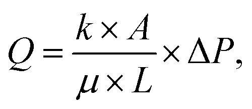
To validate the constant water flow rate by controlling the internal pressure with a variation of the aperture sizes of the OGIM, the water flow rates were measured with the custom-built water flow control system with the OGIM. The experiments for proving that the aperture size of the OGIM can function as a valve that controls the water flow rate were carried out. Here, based on the results in Fig. 4, the experiment was conducted using a flow rate of less than 0.5 LPM, which is the valving capacity of the single-layered OGIM. When the diameter of the OGIM aperture is 20 μm, 40 μm, 50 μm and 100 μm, the maintained internal pressure was at 3.6 kPa, 1.8 kPa, 1.4 kPa and 0.7 kPa (Fig. 5a). To address the issue of the standard manufacturing tolerances for stencils, the aperture sizes are statistically measured. The OM images of membranes for the D100, D50, D40 and D20 are shown in Fig. S5.† The diameter of the PDMS pillars are 98.2 ± 1.44 μm, 50.78 ± 0.77 μm, 40.75 ± 0.38 μm, and 18.89 ± 0.34 μm for D100, D50, D40, and D20, respectively. However, the aperture size of the fabricated polymer stencils has tolerances of 93.1 ± 1.42 μm, 49.7 ± 0.57 μm, 41.2 ± 0.78 μm, and 18.5 ± 0.87 μm for D100, D50, D40, and D20, respectively. Although there may be slight inaccuracies in pressure measurements due to these manufacturing tolerances, they do not significantly affect the critical pressure as exhibited in Fig. 5. And it is confirmed that the critical pressure is independent on the oil loading amount (Fig. S6†). The stable water flowing is confirmed, which is derived from the constant internal pressure (Fig. 5b). The detailed values are provided in Table S5.† Since the actual water flowing part is the same, the water flow rate (Q) and the system internal pressure (ΔP) can be expressed in a linear equation with constant dynamic viscosity (μ), length of the pipe (L), permeability (k), cross-sectional area (A) in Darcy's law as below:
 | (4-1) |
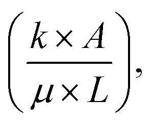 which is defined as gradient, is a system-specific value and is determined by the water flowing part. The gradient can be calculated through the experiment because there is only one variable existing in eqn (4-1), and the gradient was measured to be 0.0155 ml kPa−1 in this study. Also, the tendency that the measured data is following the regression line of Q = 0.0155 × ΔP is verified as shown in Fig. 5c. Since the internal pressure (ΔP) is maintained at the Pc of OGIM, ΔP can be substituted to
  in the eqn (4-1). Therefore, the water flow rate can be predicted directly and simply by using the aperture size of the OGIM as below:
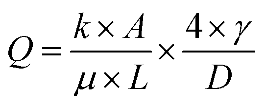 | (4-2) |
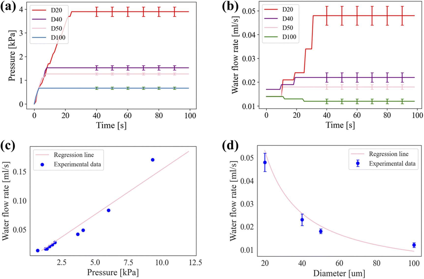 | ||
| Fig. 5 Demonstration of regulating water flow rate by using OGIM with a variation of aperture size functioning as a gas valve. (a) Measured internal system pressure with OGIM-D20, -D40, -D50, and -D100, which acts as a driving force for the water flowing. (b) Measured water flow rate depending on the aperture size of the OGIM. Error bars are inserted every five seconds after stabilization. (c) A plot of the predicted flow rate depending on the internal pressure (line) from Darcy's law and experimentally obtained data (dot). (d) A plot of the predicted flow rate depending on the aperture diameter of the OGIM (line) from Darcy's law and experimentally obtained data (dot). Error bars for five samples are inset. | ||
It can be expressed as 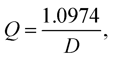 where 1.0974 was calculated by multiplying the system gradient by 4 × γ. Also, the agreement that the measured data is following the regression line is confirmed as shown in Fig. 5d. To consider the water gravity effect on the water flow rate, the pressure induced by the water inside the syringe is calculated. The height (h) of the filled water inside the syringe is 1.2 cm, and the pressure induced by the water is expressed as ρ × g × h, where ρ is density of water (1000 kg m−3) and g is gravitational acceleration (9.8 m s−2). The calculated pressure is ∼0.12 kPa, and this value is not significant compared to critical pressure of OGIMs. It will open the possibility of constructing the desired liquid-flowing system and predicting the water flow rate simply by using the specific aperture diameter of the OGIM and the internal pressure of the system.
While it is proven that the internal pressure of the chamber is controlled depending on the aperture diameter of the OGIM, leading to regulating the water flow rate, in order for the proposed water-flowing system to be stable, it should be able to act as a buffer against sudden pressure changes. Here, the OGIM-based water-flowing system is a semi-open system, hence it can react as a buffer to the undesired change in pressure. The internal pressure of the water-flowing system was suddenly changed by changing the air flow rate from the MFC. The flow rate of injecting gas flow into the system was changed in the order of 0.1 LPM, 1.5 LPM, 0.5 LPM, and 0.1 LPM and was maintained for about 20 seconds. The internal pressure and the water flow rate of the system were measured. When injecting the gas with 1.5 LPM, the internal pressure of the closed system increases sharply to 21.6 kPa in just 20 seconds, while the internal pressure of OGIM based water-flowing system only increases to 1.9 kPa. It means that even if the external gas flow rate suddenly increases by 15 times (1500%), the internal pressure of the system increases by only 26.7% compared to the critical pressure of the OGIM, and the water flow rate of the system increases by only 25% compared to the initial flow rate. Consequently, the stable internal pressure acts as a driving force, and stable water flowing is also confirmed without significant fluctuations in water flowing as Fig. 6b. The functioning as a self-actuating and buffering valve was proved without inserting or installing any complex components.
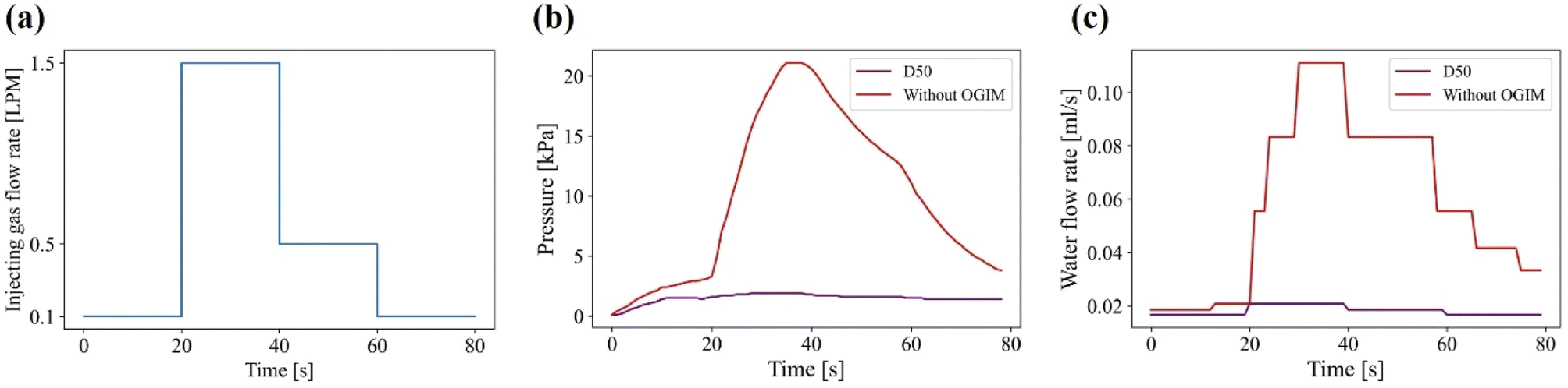 | ||
| Fig. 6 Demonstration of the damping effect of the OGIM in the condition of high gas injection rate. (a) The pneumatic gas was injected into the system in the order of 0.1 LPM, 1.5 LPM, 0.5 LPM, and 0.1 LPM every 20 seconds. (b and c) The plots of the internal pressure (b) and the water flow rate (c) of the closed system without OGIM (red) and the system with OGIM-D50 (purple). | ||
4. Conclusion
In summary, we proposed the liquid flow regulating system by controlling the pneumatic pressure with OGIM, which is arrayed micro apertures filled with gating oil. The system consists of the closed water reservoir connected with the OGIM in the condition of continuous gas injection. Since the stable pneumatic pressure acts as a driving force and induces water flow, OGIM was used as a self-actuating gas valve. When the internal pressure becomes higher than the Pc of the OGIM, the excessive gas gets immediately released outside of the system. In order to design reliable and stable OGIM systems, the effect of the viscosity of gating oil on the delay in recovering and reconfiguring which causes the pressure-oscillating phenomenon was investigated, as well as temperature dependent pressure-oscillation and valving capacity per unit open area. It is experimentally verified that the function of OGIM as a precisely controllable valve in response to the internal pressure by varying the aperture diameters of OGIM can regulate the water flow rate. Furthermore, the predictability of the water flow rate only by using the internal pressure or the aperture diameter of the OGIM was proved both theoretically and experimentally. The proposed liquid flow controller has an advantage not only in setting the desired water flow rate simply by varying the aperture diameters but also in its operating pressure range, valve size, and the ways to install to the system can be customized in various ways with a low cost. The OGIM based valve system is expected to be applied to diverse applications such as microfluidics systems, biomedical drug injection devices, and pressurized water supply systems.Conflicts of interest
The authors declare that they have no known competing financial interests or personal relationships that could have appeared to influence the work reported in this paper.Acknowledgements
This work was supported by the National Research Foundation (NRF) of Korea (NRF-2021M3H4A1A02042957) and was also supported by Incheon National University Research Grant in 2021 (2021-0010).References
- A. Raj, P. P. Suthanthiraraj and A. Sen, Microfluid. Nanofluid., 2018, 22, 1–25 CrossRef CAS.
- T. Braschler, L. Metref, R. Zvitov-Marabi, H. Van Lintel, N. Demierre, J. Theytaz and P. Renaud, Lab Chip, 2007, 7, 420–422 RSC.
- C. Fütterer, N. Minc, V. Bormuth, J.-H. Codarbox, P. Laval, J. Rossier and J.-L. Viovy, Lab Chip, 2004, 4, 351–356 RSC.
- L. Bik, M. B. van Doorn, E. Biskup, V. K. Ortner, M. Haedersdal and U. H. Olesen, Lasers Surg. Med., 2021, 53, 141–147 CrossRef PubMed.
- W. Zeng, S. Li and Z. Wang, Sens. Actuators, A, 2015, 233, 542–547 CrossRef CAS.
- W. Zeng and H. Fu, Chem. Eng. Res. Des., 2020, 160, 321–325 CrossRef CAS.
- A. Singh, Nucl. Eng. Des., 1982, 72, 197–204 CrossRef.
- R. Wang, X. Xiang, C. Zong, F. Zheng and X. Song, 2019 IEEE 8th International Conference on Fluid Power and Mechatronics (FPM), 2019, pp. 338–345 Search PubMed.
- I. Doh and Y.-H. Cho, Lab Chip, 2009, 9, 2070–2075 RSC.
- X. Zhang, K. Xia and A. Ji, Sens. Actuators, B, 2020, 304, 127331 CrossRef CAS.
- B. Yang and Q. Lin, J. Microelectromech. Syst., 2007, 16, 411–419 Search PubMed.
- E. P. Kartalov, C. Walker, C. R. Taylor, W. F. Anderson and A. Scherer, Proc. Natl. Acad. Sci. U. S. A., 2006, 103, 12280–12284 CrossRef CAS PubMed.
- E. Chappel, Appl. Sci., 2020, 10, 8858 CrossRef CAS.
- X. Zhang, A. E. Oseyemi, K. Ma and S. Yu, Sens. Actuators, B, 2022, 367, 132035 CrossRef CAS.
- X. Hou, Y. Hu, A. Grinthal, M. Khan and J. Aizenberg, Nature, 2015, 519, 70–73 CrossRef CAS PubMed.
- Z. Sheng, H. Wang, Y. Tang, M. Wang, L. Huang, L. Min, H. Meng, S. Chen, L. Jiang and X. Hou, Sci. Adv., 2018, 4, eaao6724 CrossRef PubMed.
- S. Wang, Y. Zhang, Y. Han, Y. Hou, Y. Fan and X. Hou, Acc. Mater. Res., 2021, 2, 407–419 CrossRef CAS.
- W. Liu, M. Wang, Z. Sheng, Y. Zhang, S. Wang, L. Qiao, Y. Hou, M. Zhang, X. Chen and X. Hou, Ind. Eng. Chem. Res., 2019, 58, 11976–11984 CrossRef CAS.
- B. Chen, M. Zhang, Y. Hou, H. Wang, R. Zhang, Y. Fan, X. Chen and X. Hou, Innovation, 2022, 3, 100231 Search PubMed.
- X. Xu, J. Liu, M. Cao, J. Zhang, X. Huang and X. Hou, Membranes, 2022, 12, 642 CrossRef CAS PubMed.
- J. Wang, X. Ma, L. Su, C. Zhang, X. Dong, C. Teng, L. Jiang and C. Yu, Sep. Purif. Technol., 2022, 282, 120114 CrossRef CAS.
- D. Qin, Y. Xia and G. M. Whitesides, Nat. Protoc., 2010, 5, 491 CrossRef CAS PubMed.
- C. Seol, S. Jang, J. Lee, L. V. Nam, T. A. Pham, S. Koo, K. Kim, J.-H. Jang, S. M. Kim and S. J. Yoo, ACS Sustainable Chem. Eng., 2021, 9, 5884–5894 CrossRef CAS.
- H. Cho, S. Moon Kim, Y. Sik Kang, J. Kim, S. Jang, M. Kim, H. Park, J. Won Bang, S. Seo and K.-Y. Suh, Nat. Commun., 2015, 6, 8484 CrossRef CAS PubMed.
- M. Kim, J. Lee, J. Kim, S. Jang and S. M. Kim, Polymers, 2021, 13, 4361 CrossRef CAS PubMed.
- S. M. Kim, J. H. Koh, H. S. Suh, H. Yoon, K.-Y. Suh and K. Char, Soft Matter, 2013, 9, 4145–4149 RSC.
- S. Orvalho, M. C. Ruzicka, G. Olivieri and A. Marzocchella, Chem. Eng. Sci., 2015, 134, 205–216 CrossRef CAS.
- G. S. Sariyerli, O. Sakarya and U. Y. Akcadag, Int. J. Metrol. Qual. Eng., 2018, 9, 7 CrossRef.
- A. Wolak, G. Zając and T. Słowik, Sensors, 2021, 21, 2530 CrossRef CAS PubMed.
- P.-G. Gennes, F. Brochard-Wyart and D. Quéré, Capillarity and Wetting Phenomena: Drops, Bubbles, Pearls, Waves, Springer, 2004 Search PubMed.
- C. Seol, S. Jang, J. Kim, T.-S. Jun and S. M. Kim, Soft Matter, 2018, 14, 9522–9527 RSC.
Footnote |
| † Electronic supplementary information (ESI) available. See DOI: https://doi.org/10.1039/d3ra03017b |
| This journal is © The Royal Society of Chemistry 2023 |