
 Open Access Article
 This Open Access Article is licensed under a Creative Commons Attribution-Non Commercial 3.0 Unported Licence
UV ozone treatment for oxidization of spiro-OMeTAD hole transport layer†
Ryotaro Hayashia,
Ayane Murotaa,
Kengo Okaa,
Yuhi Inadab and
Kenichi Yamashita *a
*a
aFaculty of Electrical Engineering and Electronics, Kyoto Institute of Technology, Matsugasaki, Sakyo-ku, Kyoto 606-8585, Japan. E-mail: yamasita@kit.ac.jp
bFaculty of Material Science and Engineering, Kyoto Institute of Technology, Matsugasaki, Sakyo-ku, Kyoto 606-8585, Japan
First published on 20th June 2023
Abstract
For practical application of perovskite photovoltaic devices, it is vital to choose an appropriate carrier extraction material with high mobility, high conductivity, and appropriate molecular energy levels. One of the most frequently used hole transport materials, spiro-OMeTAD, is known to show an improvement in its electrical properties after the oxidation reaction. However, this oxidation reaction is generally accomplished by simple atmospheric exposure, often taking one or more nights under atmospheric conditions, and thus the development of a rapid oxidation strategy without the degradation of device performance is strongly required. Here, we propose a rapid and reproducible oxidation route employing a UV ozone treatment process that enables quick oxidation of spiro-OMeTAD in solution, as short as 30 seconds. Optical and electrical characterization reveals that this method modifies the highest occupied molecular orbital energy level of spiro-OMeTAD to reduce the voltage loss, and also improves the conductivity and mobility, leading to the enhancement in the photovoltaic properties. This finding will provide useful insights into the further development of spiro-OMeTAD-based perovskite solar cell devices.
Introduction
Perovskite solar cells are one of the most promising next-generation solar cells, with a certified power conversion efficiency of 25.7%.1–3 It is apparent that the most important requirement for achieving excellent device performance is perovskite light-absorbing layers having excellent photoelectric conversion ability.4–8 Meanwhile, in order to transport photogenerated carriers to electrodes, selection of carrier extraction materials with high mobility, high conductivity, and appropriate molecular energy levels is also important.9–12 So far, 2,2′,7,7′-tetrakis-(N,N-di-4-methoxyphenylamino)-9,9′-spirobifluorene (spiro-OMeTAD) has been widely used as the hole transport material in perovskite solar cells with high power conversion efficiency.13 This material exhibits a large band gap (∼3.0 eV), deep highest-occupied molecular orbital (HOMO) energy, high melting point, and thermal stability in device operation,14–17 which are very compatible features with perovskite absorption layers. However, as non-doped spiro-OMeTAD does not exhibit sufficiently high conductivity and hole mobility, some kinds of additives are generally used to enhance the electrical properties.18 Most typically, lithium bis(trifluoromethanesulfonyl)imide (LiTFSI) and 4-tert-butylpyridine (tBP) are used as doping material and additive, respectively, which accelerate the oxidation of spiro-OMeTAD.19–21 It has been suggested that tBP prevents the phase separation between LiTFSI and spiro-OMeTAD, and also provides excellent interfacial contact with the perovskite layer.22It is known that LiTFSI is responsible for promoting the redox reaction of spiro-OMeTAD as shown below.19,20
| Spiro-OMeTAD + O2 ↔ spiro-OMeTAD+ + O2− | (1) |
| Spiro-OMeTAD+ + O2− + LiTFSI ↔ spiro-OMeTAD+ + TFSI− + LixOy | (2) |
Ionized spiro-OMeTAD (spiro-OMeTAD+) produced by the oxidation process can increase hole concentration in spiro-OMeTAD.23 The density of spiro-OMeTAD+ is positively correlated with electrical conductivity.24,25 Furthermore, the existence of spiro-OMeTAD+ can improve the hole extraction ability from perovskite absorbing layer, leading to the higher power conversion efficiency. From these aspects, promoting the oxidation of spiro-OMeTAD is an essential factor for improving the device performance. In most studies, however, the oxidation reactions are made by simple atmospheric exposure, often taking one or more nights.24 The simple atmospheric exposure is of general concern as it affects the stability of PSCs. In particular, moisture and oxygen in air will accelerate the decomposition of perovskite, further reducing the device performance and stability.25,26 To accelerate the oxidation of spiro-OMeTAD, the use of Co(III) complexes,27,28 Cu(II) complexes,29 CuSCN (or CuI),30 ionic liquids,31 and ex situ synthesized p-type dopants such as spiro-OMeTAD2+(TFSI−)2 radicals have been suggested.32,33 However, these dopants show low solubility in spiro-OMeTAD film and/or require the additional atmospheric exposure process to obtain the desired electrical properties. Also, they may produce undesirable byproducts that behave as impurities. As these are crucial drawbacks for the large-scale production and hinder the commercialization, an oxidation process that can reduce the atmospheric exposure time without the degradation of final device performance is required.
In this study, we focus on UV ozone treatment process as a convenient way to promote the oxidation of spiro-OMeTAD in solution (see Fig. 1). The O− ions (reactive oxygen species) produced by the UV ozone treatment are activated to the electronic excited state and act as a good oxidant for spiro-OMeTAD. As a result, this process enables the rapid oxidation of spiro-OMeTAD, as short as 30 seconds. Furthermore, we show that the oxidized spiro-OMeTAD+ modifies the HOMO level energy of spiro-OMeTAD to improve the energy alignment with the valence band of perovskite, as well as improvements in the conductivity and mobility. These results demonstrate that the UV ozone treatment is promising as a quick oxidation scheme of spiro-OMeTAD, which helps the development of mass production processes for the perovskite solar cell modules.
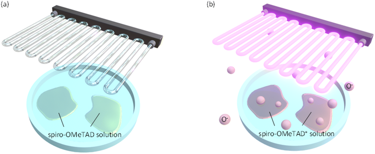 | ||
| Fig. 1 Schematic depiction of UV ozone treatment for spiro-OMeTAD in solution. (a) Before and (b) after the treatments. The O− ions generated by a UV ozone treatment promote oxidization of spiro-OMeTAD molecule. After oxidization, solution is used for spin-coating. | ||
Materials and methods
Preparation of precursor solutions
Aqueous solution of SnO2 (15% in H2O, colloidal dispersion) was purchased from Alfa Aeser. Lead(II) iodide (PbI2), lead(II) bromide (PbBr2), formamidine hydroiodide (FAI, low water content), formamidine bromide (FABr), and cesium iodide (CsI) were purchased from TCI. Phenylethylammonium iodide (PEAI) was purchased from Greatcell solar. Spiro-OMeTAD was purchased from Sigma-Aldrich. All chemicals were used as provided.For preparing the solution for hole transport layer (HTL), spiro-OMeTAD (50 mg) was dissolved in chlorobenzene (CBZ, 700 μL). This solution was then mixed with LiTFSI (14 μL of acetonitrile solution dissolving 155.03 mg of LiTFSI) and tBP (25.2 μL) and stirred at room temperature for 20 minutes, followed by the filtering using a hydrophobic syringe filter with a pore diameter of 1 μm.34 The mixture was then held at room temperature for 20 minutes and spread on a Petri dish. The mixture was exposed to UV ozone in a UV ozone cleaner (PC-440, Bioforce Nanoscience) for 0–2 minutes. The UV ozone cleaner emitted UV lights at wavelengths of 184.9 nm and 253.7 nm. The total power of UV light was ∼20 mW cm−2.
For preparation of SnO2 precursor solution, the purchased 15% aqueous solution was mixed with distilled water so that the SnO2 concentration is 7.5%. The prepared solution was sonicated for 30 minutes and filtered using a hydrophilic syringe filter with a pore diameter of 0.45 μm.
Precursor solution for perovskite absorption layer was prepared by mixing three solutions: solutions of FAPbI3, FAPbBr3, and CsPbBr3 with mixed solvent of N,N-dimethylformamide (DMF) and dimethyl sulfoxide (DMSO). For the solutions of FAPbI3 and FAPbBr3, the mixing volume ratio of DMF![[thin space (1/6-em)]](https://www.rsc.org/images/entities/char_2009.gif) :DMSO was 4:1. For the solution of CsPbBr3, DMSO:DMF = 4:1. For preparing the solution of FAPbI3, 599.3 mg of PbI2 powder was dissolved in 1.0 mL of the DMF/DMSO mixed solvent. Then, 180.0 mg of FAI powder was added to 947.0 μL of the DMF/DMSO solution of PbI2. To prepare the solution of FAPbBr3, 201.9 mg of PbBr2 powder was dissolved in 0.5 mL of the DMF/DMSO mixed solvent. Then, 50.0 mg of FABr powder was added to 362.0 μL of the DMF/DMSO solution of PbBr2. For preparing the solution of CsPbI3, 149.8 mg of PbI2 powder was dissolved in 250.0 μL of the DMSO/DMF mixed solvent. Following that, 50 mg of CsI powder was added to 174.2 μL of the solution. Finally, we mixed the solution of FAPbI3 (750 μL), the solution of FAPbBr3 (100 μL), and the solution of CsPbI3 (150 μL) and filtered the mixed solution using a hydrophobic syringe filter with a pore diameter of 1 μm. The stoichiometric ratio in the mixed solution leads to the resultant composition of perovskite film fabricated by spin-coating method to be FA0.9Cs0.1Pb(I0.85Br0.15)3. For preparation of solution of PEAI, 8.94 mg of PEAI powder was dissolved in 3.0 mL of the 2-propanol as the solvent.
:DMSO was 4:1. For the solution of CsPbBr3, DMSO:DMF = 4:1. For preparing the solution of FAPbI3, 599.3 mg of PbI2 powder was dissolved in 1.0 mL of the DMF/DMSO mixed solvent. Then, 180.0 mg of FAI powder was added to 947.0 μL of the DMF/DMSO solution of PbI2. To prepare the solution of FAPbBr3, 201.9 mg of PbBr2 powder was dissolved in 0.5 mL of the DMF/DMSO mixed solvent. Then, 50.0 mg of FABr powder was added to 362.0 μL of the DMF/DMSO solution of PbBr2. For preparing the solution of CsPbI3, 149.8 mg of PbI2 powder was dissolved in 250.0 μL of the DMSO/DMF mixed solvent. Following that, 50 mg of CsI powder was added to 174.2 μL of the solution. Finally, we mixed the solution of FAPbI3 (750 μL), the solution of FAPbBr3 (100 μL), and the solution of CsPbI3 (150 μL) and filtered the mixed solution using a hydrophobic syringe filter with a pore diameter of 1 μm. The stoichiometric ratio in the mixed solution leads to the resultant composition of perovskite film fabricated by spin-coating method to be FA0.9Cs0.1Pb(I0.85Br0.15)3. For preparation of solution of PEAI, 8.94 mg of PEAI powder was dissolved in 3.0 mL of the 2-propanol as the solvent.
Device fabrication
Photovoltaic devices studied here consist of a layered structure of glass/ITO/SnO2/FA0.9Cs0.1Pb(I0.85Br0.15)3/PEAI/spiro-OMeTAD/Au. To fabricate the device, a glass/ITO substrate was cleaned with detergent (diluted 10 times with distilled water), acetone, and 2-propanol, in an ultrasonic bath. Next the SnO2 precursor solution was spin-coated at 4000 rpm for 30 seconds and then annealed at 150 °C for 30 minutes. Before and after coating the SnO2 precursor solution, the sample was exposed to UV light for 15 minutes under ozone atmosphere to increase the hydrophilicity. After that, the samples were transferred into a glove box (UNICO, UL-1000A) filled with dry nitrogen gas (<0.7% RH). To fabricate the perovskite absorption layer, perovskite precursor solution was spin-coated by the 1-step anti-solvent method. The sequential spin-coating was performed at 1000 rpm for 10 seconds followed by that at 6000 rpm for 20 seconds. As the anti-solvent crystallization procedure, CBZ was dropped at 10 seconds from the start time of the second spin-coating sequence. The perovskite film was annealed at 100 °C for 1 hour. Onto the perovskite layer, the spiro-OMeTAD HTL was fabricated with the spin coating method at 500 rpm for 5 seconds followed by that at 4000 rpm for 35 seconds. The substrate was dried at room temperature for 30 minutes. Finally, a gold top electrode was deposited by vacuum evaporation.Characterizations
UV absorption measurements were performed by using a UV-vis spectrometer (UV-2550, Shimadzu). PYS measurement was employed for evaluating the HOMO energy level of spiro-OMeTAD by using an ionization energy measurement system (BIP-KV202GTGK, Bunkoukeiki).Conductivity and mobility were evaluated by measuring current density–voltage (J–V) characteristics. We used a source meter (Model 2400, Keithley) for the electrical measurements. When we measured the photovoltaic performance, a solar simulator (XES-40SI, SAN-EI) was employed. The illumination condition was 100 mW cm−2 of AM1.5G. The current density–voltage curves measured under both the forward and reverse voltage scanning directions were recorded.
The J–V curve measured for a very thin conductive film can be distinguished into two regions: the ohmic region at low applied voltages and the SCLC region at high applied voltages. In the ohmic region, the current increases linearly with the applied voltage. When the voltage is further increased, the SCLC region is reached and the current shows a quadratic response. Using the J–V data in the SCLC region, the mobility μh is calculated according to the Mott–Gurney equation as shown below.
 | (3) |
Results and discussion
To accelerate the oxidation of spiro-OMeTAD, the excited state of O− ion plays an important role. UV radiation at 184.9 nm decomposes molecular oxygen in the atmosphere, forming atomic oxygen. The atomic oxygen combines with a molecular oxygen in the atmosphere and forms ozone. Ozone is then UV-irradiated further at a wavelength of 253.7 nm and is decomposed again to the excited O− ions. The O− ions act as the oxidant for spiro-OMeTAD. In this study, we apply the UV ozone treatment for spiro-OMeTAD in chlorobenzene solution (see Fig. 1).Progress of oxidation with UV ozone treatment is monitored by absorption spectroscopy. Fig. 2 shows absorbance spectra of spiro-OMeTAD films at various UV ozone treatment times. A strong absorption peak around 380 nm is attributed to the non-oxidized spiro-OMeTAD. This peak position does not change even after the UV treatment, suggesting that the spiro-OMeTAD undergoes no significant degradation upon the UV exposure. On the other hand, the appearance of a relatively small peak around ∼530 nm is a signal from the oxidized spiro-OMeTAD+.19,24,35 This signal becomes strong with UV ozone treatment time and demonstrates that the O− ion acts as the oxidizer for spiro-OMeTAD.
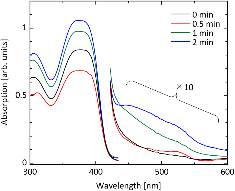 | ||
| Fig. 2 UV-vis absorption spectra of spiro-OMeTAD before and after UV ozone treatment. An absorption peak observed at ∼380 nm is attributed to the non-oxidized spiro-OMeTAD. A relatively small signal around ∼530 nm, which is grown by UV ozone treatment, is a signal from the oxidized spiro-OMeTAD+. | ||
Next, we evaluate the energy levels of spiro-OMeTAD varied with UV ozone treatment time. Photoelectron yield spectroscopy (PYS) is employed to measure the ionization energy as shown in Fig. S1 in the ESI.† The ionization energy is found to shift from −5.126 eV to −5.143 eV by UV ozone treatment for just 30 seconds. Further UV ozone treatment leads to the larger energy shift, i.e., −5.163 eV at 1 minute and −5.184 eV at 2 minutes. This result indicates that the HOMO level energy of spiro-OMeTAD increases with the dose amount of UV ozone.
The bandgap energy (Eg) is estimated from the absorption spectroscopy. Fig. S2 in the ESI† exhibits the Tauc plot analyses for the absorption spectra of spiro-OMeTAD films. The Eg of spiro-OMeTAD without the UV ozone treatment is estimated to be 3.014 eV, whereas the Eg at the UV exposing time of 0.5, 1, and 2 minutes are 3.015 eV, 3.016 eV, and 3.015 eV, respectively, indicating that UV ozone treatment does not significantly change the Eg of spiro-OMeTAD.
From the results of PYS and absorption measurements, we find that both the HOMO and the lowest unoccupied molecular orbital (LUMO) levels are deepened with the UV ozone treatment (see Fig. 3). The oxidized spiro-OMeTAD+ ion acts as a dopant and modifies the Fermi level of spiro-OMeTAD. It has been reported that the single occupied molecular orbital (SOMO) level of oxidized spiro-OMeTAD+ ion accepts an electron from the HOMO level of spiro-OMeTAD, resulting in the increase of hole density.36,37 In other words, the UV ozone treatment results in p-type doping for spiro-OMeTAD film and deepens the HOMO and LUMO levels. We also evaluated the energy diagram of perovskite films used for solar cell device in this study, by using absorption and PYS measurements [see Fig. S3(a) and (b) in the ESI†]. The smaller offset between the valence band of perovskite (∼−5.73 eV) and the HOMO level of spiro-OMeTAD (see Fig. 3) results in the better band alignment and lower offset energy loss. This allows the fast carrier extraction from perovskite layer and suppress the nonradiative recombination at the interface due to defect states, resulting in the lower voltage loss and recombination loss.38–40
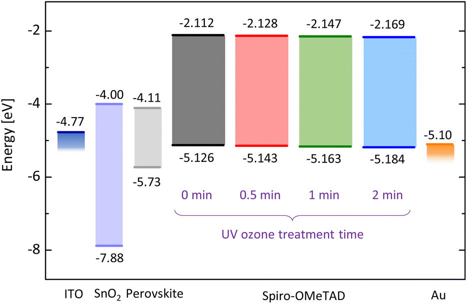 | ||
| Fig. 3 HOMO and LUMO levels of UV ozone treated spiro-OMeTAD films and energy diagram in solar cell device. Energies for spiro-OMeTAD and perovskite were evaluated from absorption and PYS measurements. | ||
Next, we investigate the electrical characteristics of UV ozone treated spiro-OMeTAD film. Fig. 4(a) shows the results of conductivity measurement for devices with the structure of glass/ITO/spiro-OMeTAD/Au. While the conductivity σ of film without UV ozone treatment is 0.252 × 10⁻⁵ S m−1, the UV exposure for 30 seconds increases σ to 0.409 × 10⁻⁵ S m−1. The increasing tendency of σ is observable up to 2 minutes and is attributed to the increased concentration in the film owing to the formation of oxidized spiro-OMeTAD+ ions.24,39,41 After 5- or 10 minutes UV ozone exposure, however, the σ begins to decrease, as shown in Fig. S4 in the ESI.† This result is likely due to the formation of unexpected by-products by the UV ozone treatment, which leads to resistive factors in the spiro-OMeTAD film. The acceleration of oxidation by UV ozone treatment is possible to improve conductivity, but the optimization of the exposure time is needed.
 | ||
| Fig. 4 Electrical characteristics of spiro-OMeTAD films as a function of UV ozone treatment time. (a) Conductivity measured for /ITO/spiro-OMeTAD/Au device. (b) Hole mobility measured for ITO/PEDOT:PSS/spiro-OMeTAD/Au device. | ||
The hole mobility μ varied with UV ozone treatment is also investigated. The space-charge-limited current (SCLC) method is applied for the hole-only device with a structure of glass/ITO/PEDOT:PSS/spiro-OMeTAD/Au.42,43 As shown in Fig. S5 in the ESI,† the current density–voltage profiles exhibit two regimes, i.e. ohmic and SCLC regimes. This result is in contrast to the case of perovskite film, in which a trap-filling regime appears in the voltage range between ohmic and SCLC, implying the low trap-state density.44 As shown in Fig. 4(b), the μ of spiro-OMeTAD film without UV ozone treatment is evaluated to be 7.52 × 10⁻⁴ cm2 V−1 s−1. After the UV ozone treatment for 30 seconds, μ increases to 7.80 × 10⁻⁴ cm2 V−1 s−1, and for 1 and 2 minutes, μ is further increased to 7.94 × 10⁻⁴ and 8.36 × 10⁻⁴ cm2 V−1 s−1, respectively. While the slight increasing trend seems to be a fluke, the almost unchanged μ indicates that the carrier density is simply proportional to σ.45
Finally, we evaluate an impact of UV ozone treatment on current–voltage characteristics in solar cell devices. The investigated solar cell structure is ITO/SnO2/perovskite/PEAI/spiro-OMeTAD/Au. A typical morphology of the perovskite surface is confirmed in a scanning electron microscopic (SEM) image [see Fig. S6(a) in the ESI†]. Cross-sectional SEM observation exhibits a good physical contact at the SnO2/perovskite and perovskite/spiro-OMeTAD interfaces [see Fig. S6(b) in the ESI†]. Fundamental structural, optical, and electrical properties of perovskite film fabricated in this study are shown in Fig. S3 in the ESI.† Note that, as our focus in this study is only the UV-ozone treatment affecting device performance, we are not concerned about the relatively low absolute values of device parameters due to unoptimized perovskite absorption layers (see Fig. S7 in the ESI†). As shown in Fig. S8(a) in the ESI,† the short-circuit current density exhibits an increased tendency with the UV ozone treatment time. This result is consistent with the enhanced conductivity and mobility shown above.41,46,47 The open-circuit voltage is also slightly improved by the UV ozone treatment [see Fig. S8(b)†] due to the deep HOMO energy level causing the low voltage loss. The filling factor is highest at the UV ozone treatment time of 30 seconds [see Fig. S8(c)†], which is consistent with the saturation tendency observed in the conductivity measurement [see Fig. 4(a)]. Overall, the power conversion efficiency (PCE) shows a maximum at the exposure time of 30 seconds as shown in Fig. 5(a). These results reveal that there is an appropriate dose amount to earn the maximum effect of UV ozone treatment.
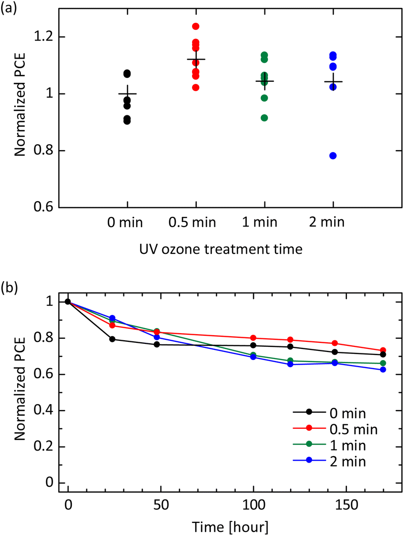 | ||
| Fig. 5 Photovoltaic characterization of perovskite solar cell with UV ozone treated spiro-OMeTAD HTL. (a) Normalized PCE of solar cell samples at various UV ozone treatment times. The data are normalized by the averaged PCE of devices without the treatment. (b) Evolution of the normalized PCE of devices left in an atmospheric environment. | ||
More importantly, the dose amount of UV ozone treatment also affects device stability. Fig. 5(b) exhibits degradation of PCE for devices left in an atmospheric environment. The initial degradation in PCE within 48 hours, which is clearly observed in pristine samples, is mitigated by UV ozone treatment. This is likely owing to a fact that the UV ozone treatment promotes a reaction of LiTFSI described in eqn (2). The well-reacted and well-stabilized Li+ complex do not affect the device stability whereas the device without UV ozone treatment is considered to have dense Li+ ions, which can migrate through the perovskite layer and accumulate in the electron transport layer (ETL), causing degradation.15,26,48 On the other hand, a long-term degradation observed after 100 hours becomes pronounced at the UV ozone treatment time of 1 or 2 minutes. This result implies that the excessive O− ions produced by the UV ozone treatment and remaining in the spiro-OMeTAD layer have a negative impact on the perovskite absorption layer. Specifically, highly active species such as O− ions are possible to decompose the perovskite structure, leading to the degradation in device performance. It is worth noting that at the UV ozone treatment time of 30 seconds, both the initial degradation and the long-term degradation are mitigated simultaneously. This result is well consistent with the initial device performance shown in Fig. 5(a) and exhibits that the UV ozone treatment as long as 30 seconds is appropriate also in terms of device stability.
Conclusions
In this study, we proposed UV ozone treatment as a rapid oxidization method of spiro-OMeTAD in solution. Absorption measurements showed that UV ozone treatment time more than 30 seconds is effective to produce the oxidized spiro-OMeTAD+. Furthermore, PYS measurements showed that UV ozone treatment modifies HOMO energy of spiro-OMeTAD so that voltage loss in solar cell device is suppressed. Electrical characterizations demonstrated that the conductivity and the mobility are also improved, which were confirmed as the enhanced PCE in solar cell devices. These results reveal that our oxidization strategy is more effective than the conventional methods, allowing for reducing the device manufacturing time. It is therefore expected to provide useful insights into the further development of spiro-OMeTAD-based perovskite solar cell devices and to contribute to the development of mass production processes of perovskite solar cell modules.Dara availability
The datasets generated during and/or analysed during the current study are available from the corresponding author on reasonable request.Author contributions
R. H. and K. Y. conceived and planned the experiments. R. H., A. M., and K. O. fabricated samples and devices, and performed absorbance measurements, PYS measurements, conductivity measurements, mobility measurements, and device characterizations. Y. I. performed X-ray diffraction measurements. R. H. and K. Y. drafted the manuscript and complied figures, with discussion of results and feedback from all authors.Conflicts of interest
The authors declare no conflict of interests.Acknowledgements
K. Y. acknowledges funding from Japan Society for the Promotion of Science, JSPS KAKENHI (No. 20KK0088, 22K18794, and 22H00215) and from JST CREST (JPMJCR20T4). The authors acknowledge Dr Y. Numata and Prof. T. Miyasaka of Toin Yokohama University for their advice on device fabrication.References
- Best Research-Cell Efficiency Chart, https://www.nrel.gov/pv/cell-efficiency.html, accessed April 6, 2023 Search PubMed.
- A. Kojima, K. Teshima, Y. Shirai and T. Miyasaka, J. Am. Chem. Soc., 2009, 131, 6050–6051 CrossRef CAS.
- O. Almora, D. Baran, G. C. Bazan, C. I. Cabrera, S. Erten-Ela, K. Forberich, F. Guo, J. Hauch, A. W. Y. Ho-Baillie, T. J. Jacobsson, R. A. J. Janssen, T. Kirchartz, N. Kopidakis, M. A. Loi, R. R. Lunt, X. Mathew, M. D. McGehee, J. Min, D. B. Mitzi, M. K. Nazeeruddin, J. Nelson, A. F. Nogueira, U. W. Paetzold, B. P. Rand, U. Rau, H. J. Snaith, E. Unger, L. Vaillant-Roca, C. Yang, H.-L. Yip and C. J. Brabec, Adv. Energy Mater., 2023, 13, 2203313 CrossRef CAS.
- S. De Wolf, J. Holovsky, S.-J. Moon, P. Löper, B. Niesen, M. Ledinsky, F.-J. Haug, J.-H. Yum and C. Ballif, J. Phys. Chem. Lett., 2014, 5, 1035–1039 CrossRef CAS PubMed.
- Z. Xiao, Z. Song and Y. Yan, Adv. Mater., 2019, 31, 1803792 CrossRef CAS PubMed.
- W.-J. Yin, T. Shi and Y. Yan, Adv. Mater., 2014, 26, 4653–4658 CrossRef CAS.
- H.-S. Duan, H. Zhou, Q. Chen, P. Sun, S. Luo, T.-B. Song, B. Bob and Y. Yang, Phys. Chem. Chem. Phys., 2014, 17, 112–116 RSC.
- S. O. Ali Ahmad, A. Ashfaq, M. U. Akbar, M. Ikram, K. Khan, F. Wang, M. Ikram and A. Mahmood, J. Mater. Chem. C, 2021, 9, 14065–14092 RSC.
- L. Calió, S. Kazim, M. Grätzel and S. Ahmad, Angew. Chem., Int. Ed., 2016, 55, 14522–14545 CrossRef PubMed.
- J. H. Kim, P.-W. Liang, S. T. Williams, N. Cho, C.-C. Chueh, M. S. Glaz, D. S. Ginger and A. K.-Y. Jen, Adv. Mater., 2015, 27, 695–701 CrossRef CAS PubMed.
- N. J. Jeon, H. Na, E. H. Jung, T.-Y. Yang, Y. G. Lee, G. Kim, H.-W. Shin, S. Il Seok, J. Lee and J. Seo, Nat. Energy, 2018, 3, 682–689 CrossRef CAS.
- A. Murota, K. Oka, R. Hayashi, K. Fujiwara, T. Nishida, K. Kobayashi, Y. Numata and K. Yamashita, Appl. Phys. Lett., 2022, 120, 191604 CrossRef CAS.
- M. Jeong, I. W. Choi, E. M. Go, Y. Cho, M. Kim, B. Lee, S. Jeong, Y. Jo, H. W. Choi, J. Lee, J.-H. Bae, S. K. Kwak, D. S. Kim and C. Yang, Science, 2020, 369, 1615–1620 CrossRef CAS.
- L. K. Ono, P. Schulz, J. J. Endres, G. O. Nikiforov, Y. Kato, A. Kahn and Y. Qi, J. Phys. Chem. Lett., 2014, 5, 1374–1379 CrossRef CAS PubMed.
- Z. Hawash, L. K. Ono, S. R. Raga, M. V. Lee and Y. Qi, Chem. Mater., 2015, 27, 562–569 CrossRef CAS.
- J. Salbeck, N. Yu, J. Bauer, F. Weissörtel and H. Bestgen, Synth. Met., 1997, 91, 209–215 CrossRef CAS.
- J. Salbeck, F. Weissörtel and J. Bauer, Macromol. Symp., 1998, 125, 121–132 CrossRef CAS.
- D. Poplavskyy and J. Nelson, J. Appl. Phys., 2003, 93, 341–346 CrossRef CAS.
- U. B. Cappel, T. Daeneke and U. Bach, Nano Lett., 2012, 12, 4925–4931 CrossRef CAS PubMed.
- Z. Hawash, L. K. Ono and Y. Qi, Adv. Mater. Interfaces, 2016, 3, 1600117 CrossRef.
- E. J. Juarez-Perez, M. R. Leyden, S. Wang, L. K. Ono, Z. Hawash and Y. Qi, Chem. Mater., 2016, 28, 5702–5709 CrossRef CAS.
- S. Wang, M. Sina, P. Parikh, T. Uekert, B. Shahbazian, A. Devaraj and Y. S. Meng, Nano Lett., 2016, 16, 5594–5600 CrossRef CAS PubMed.
- G. Ren, W. Han, Y. Deng, W. Wu, Z. Li, J. Guo, H. Bao, C. Liu and W. Guo, J. Mater. Chem. A, 2021, 9, 4589–4625 RSC.
- S. Wang, W. Yuan and Y. S. Meng, ACS Appl. Mater. Interfaces, 2015, 7, 24791–24798 CrossRef CAS.
- R. L. Forward, K. Y. Chen, D. M. Weekes, D. J. Dvorak, Y. Cao and C. P. Berlinguette, ACS Energy Lett., 2019, 4, 2547–2551 CrossRef CAS.
- I. Lee, J. H. Yun, H. J. Son and T.-S. Kim, ACS Appl. Mater. Interfaces, 2017, 9, 7029–7035 CrossRef CAS.
- J. Burschka, A. Dualeh, F. Kessler, E. Baranoff, N.-L. Cevey-Ha, C. Yi, M. K. Nazeeruddin and M. Grätzel, J. Am. Chem. Soc., 2011, 133, 18042–18045 CrossRef CAS PubMed.
- L. Nakka, A. G. Aberle and F. Lin, Energies, 2023, 16, 354 CrossRef CAS.
- C. Chen, W. Zhang, J. Cong, M. Cheng, B. Zhang, H. Chen, P. Liu, R. Li, M. Safdari, L. Kloo and L. Sun, ACS Energy Lett., 2017, 2, 497–503 CrossRef CAS.
- M. Li, Z.-K. Wang, Y.-G. Yang, Y. Hu, S.-L. Feng, J.-M. Wang, X.-Y. Gao and L.-S. Liao, Adv. Energy Mater., 2016, 6, 1601156 CrossRef.
- C. Geffroy, E. Grana, T. Bessho, S. Almosni, Z. Tang, A. Sharma, T. Kinoshita, F. Awai, E. Cloutet, T. Toupance, H. Segawa and G. Hadziioannou, ACS Appl. Energy Mater., 2020, 3, 1393–1401 CrossRef CAS.
- W. H. Nguyen, C. D. Bailie, E. L. Unger and M. D. McGehee, J. Am. Chem. Soc., 2014, 136, 10996–11001 CrossRef CAS PubMed.
- B. Tan, S. R. Raga, A. S. R. Chesman, S. O. Fürer, F. Zheng, D. P. McMeekin, L. Jiang, W. Mao, X. Lin, X. Wen, J. Lu, Y.-B. Cheng and U. Bach, Adv. Energy Mater., 2019, 9, 1901519 CrossRef.
- M. Saliba, J.-P. Correa-Baena, C. M. Wolff, M. Stolterfoht, N. Phung, S. Albrecht, D. Neher and A. Abate, Chem. Mater., 2018, 30, 4193–4201 CrossRef CAS.
- X. Wang, J. Wu, Y. Yang, X. Liu, Q. Guo, Z. Song, G. Li, Z. Lan and M. Huang, J. Mater. Chem. A, 2019, 7, 13256–13264 RSC.
- T. H. Schloemer, J. A. Christians, J. M. Luther and A. Sellinger, Chem. Sci., 2019, 10, 1904–1935 RSC.
- K. Walzer, B. Maennig, M. Pfeiffer and K. Leo, Chem. Rev., 2007, 107, 1233–1271 CrossRef CAS.
- P. Caprioglio, M. Stolterfoht, C. M. Wolff, T. Unold, B. Rech, S. Albrecht and D. Neher, Adv. Energy Mater., 2019, 9, 1901631 CrossRef.
- Y. Cho, H. D. Kim, J. Zheng, J. Bing, Y. Li, M. Zhang, M. A. Green, A. Wakamiya, S. Huang, H. Ohkita and A. W. Y. Ho-Baillie, ACS Energy Lett., 2021, 6, 925–933 CrossRef CAS.
- R. J. E. Westbrook, I. Sanchez-Molina, J. Manuel Marin-Beloqui, H. Bronstein and S. A. Haque, J. Phys. Chem. C, 2018, 122, 1326–1332 CrossRef CAS.
- J. Kong, Y. Shin, J. A. Röhr, H. Wang, J. Meng, Y. Wu, A. Katzenberg, G. Kim, D. Y. Kim, T.-D. Li, E. Chau, F. Antonio, T. Siboonruang, S. Kwon, K. Lee, J. R. Kim, M. A. Modestino, H. Wang and A. D. Taylor, Nature, 2021, 594, 51–56 CrossRef CAS PubMed.
- V. M. Le Corre, E. A. Duijnstee, O. El Tambouli, J. M. Ball, H. J. Snaith, J. Lim and L. J. A. Koster, ACS Energy Lett., 2021, 6, 1087–1094 CrossRef CAS PubMed.
- M. Taukeer Khan, A. Almohammedi, S. Kazim and S. Ahmad, Chem. Rec., 2020, 20, 452–465 CrossRef CAS PubMed.
- T. Webb, X. Liu, R. J. E. Westbrook, S. Kern, M. T. Sajjad, S. Jenatsch, K. D. G. I. Jayawardena, W. H. K. Perera, I. P. Marko, S. Sathasivam, B. Li, M. Yavari, D. J. Scurr, M. R. Alexander, T. J. Macdonald, S. A. Haque, S. J. Sweeney and W. Zhang, Adv. Energy Mater., 2022, 12, 2200666 CrossRef CAS.
- S. Olthof, S. Mehraeen, S. K. Mohapatra, S. Barlow, V. Coropceanu, J.-L. Brédas, S. R. Marder and A. Kahn, Phys. Rev. Lett., 2012, 109, 176601 CrossRef PubMed.
- I. Gelmetti, N. F. Montcada, A. Pérez-Rodríguez, E. Barrena, C. Ocal, I. García-Benito, A. Molina-Ontoria, N. Martín, A. Vidal-Ferran and E. Palomares, Energy Environ. Sci., 2019, 12, 1309–1316 RSC.
- V. M. Le Corre, M. Stolterfoht, L. Perdigón Toro, M. Feuerstein, C. Wolff, L. Gil-Escrig, H. J. Bolink, D. Neher and L. J. A. Koster, ACS Appl. Energy Mater., 2019, 2, 6280–6287 CrossRef CAS.
- Z. Li, C. Xiao, Y. Yang, S. P. Harvey, D. H. Kim, J. A. Christians, M. Yang, P. Schulz, S. U. Nanayakkara, C.-S. Jiang, J. M. Luther, J. J. Berry, M. C. Beard, M. M. Al-Jassim and K. Zhu, Energy Environ. Sci., 2017, 10, 1234–1242 RSC.
Footnote |
| † Electronic supplementary information (ESI) available. See DOI: https://doi.org/10.1039/d3ra02315j |
| This journal is © The Royal Society of Chemistry 2023 |