
 Open Access Article
 This Open Access Article is licensed under a Creative Commons Attribution-Non Commercial 3.0 Unported Licence
Self-diffusion in polycrystalline Li1+xTi2−xAlx(PO4)3 (0.2 ≤ x ≤ 0.4) samples followed by 7Li PFG (pulse field gradient) NMR spectroscopy†
Virginia Diez-Gómez a,
Isabel Sobradosa,
Cristina Ruiz-Santaquiteriaa,
Wilmer Buchelia,
Ricardo Jiménez*ab and
Jesús Sanza
a,
Isabel Sobradosa,
Cristina Ruiz-Santaquiteriaa,
Wilmer Buchelia,
Ricardo Jiménez*ab and
Jesús Sanza
aDpto. Energy, Materials Science Institute of Madrid, ICMM-CSIC, Cantoblanco, 28049 Madrid, Spain. E-mail: riqjim@icmm.csic.es
bDpto. Materials for the Information Technologies, Materials Science Institute of Madrid, ICMM-CSIC, Cantoblanco, 28049 Madrid, Spain
First published on 27th April 2023
Abstract
Short and long range lithium motions in powder Li1+xTi2−xAlx(PO4)3 (LTAP) NASICON compounds prepared by ceramic (x = 0.2 and 0.4) and sol–gel (x = 0.3 and 0.4) routes are discussed. ND diffraction and MAS-NMR spectroscopy were previously used to investigate structural features of these compounds. In particular, Fourier map differences showed that the amount of Li atoms allocated at M3 increases at the expense of M1 sites when the Li content increases. In this work, PFG-NMR results show that diffusion coefficients rise with the amount of lithium and temperature. The restricted diffusion inside NASICON particles is compared with “free” diffusion processes. At 300 K, diffusion coefficients DPFG ∼ 5 × 10⁻¹² m2 s−1 have been deduced in ceramic x = 0.2 and 0.4 samples, decreasing with diffusion time Δ used in PFG experiments. In sol–gel samples, diffusion coefficients are near those of ceramic samples, but decrease faster with diffusion Δ times, as a consequence of the Li confinement inside sub-micrometric crystallites. The NMR spin-echo signal displays minima at specific q(γgδ) values that are related to the crystallite size. From Rdif ∼ qm−1 distances, calculated from the position of minima, and from diffusion coefficients deduced for high Δ values, the mean crystallite size was estimated. Finally, from the temperature dependence of conductivity and diffusion coefficients, the activation energy and charge carriers concentrations were determined.
Introduction
LiR2(PO4)3 NASICON-type phosphates are considered promising electrolytes for all solid-state lithium (ASSB) batteries because of their chemical stability against water and CO2, and their high three-dimensional mobility.1,2 The structural investigation of Li LiR2(PO4)3 compounds showed that the NASICON network is built of LiR2(PO4)3 lanterns, that share oxygen atoms with neighbouring units to form 3D conduction channels.3 In Ge and Ti phases, a rhombohedral R![[3 with combining macron]](https://www.rsc.org/images/entities/char_0033_0304.gif) c space group was deduced at RT, however, in Sn, Zr and Hf phases, an additional triclinic C
c space group was deduced at RT, however, in Sn, Zr and Hf phases, an additional triclinic C![[1 with combining macron]](https://www.rsc.org/images/entities/char_0031_0304.gif) one was detected at lower temperatures.4–8 In LiR2(PO4)3 doped compounds, the amount of Li charge carriers can be modified by changing the valence of R cations. In solid solutions Li1+xTi2−xRx3+(PO4)3 (R3+ = Al, Sc, In), the amount of lithium increases with trivalent cations, improving considerably Li mobility at room temperature (σdc ∼ 10−3 S cm−1).9–11 Taken into account the big increment of conductivity of Li1+xTi2−xAlx(PO4)3 (LTAP) with respect to that of LiTi2(PO4)3, structural investigations were addressed to elucidate Li motion mechanisms.
one was detected at lower temperatures.4–8 In LiR2(PO4)3 doped compounds, the amount of Li charge carriers can be modified by changing the valence of R cations. In solid solutions Li1+xTi2−xRx3+(PO4)3 (R3+ = Al, Sc, In), the amount of lithium increases with trivalent cations, improving considerably Li mobility at room temperature (σdc ∼ 10−3 S cm−1).9–11 Taken into account the big increment of conductivity of Li1+xTi2−xAlx(PO4)3 (LTAP) with respect to that of LiTi2(PO4)3, structural investigations were addressed to elucidate Li motion mechanisms.
In Li1+xTi2−xAlx(PO4)3 (x = 0.2 and 0.4) samples, Fourier map-differences performed on neutron diffraction patterns recorded between RT and 500 K, showed that Li ions occupy two structural sites: M1 sites at ternary axes and M3/M3′ sites of M2 cavities disposed around ternary axes11 (Fig. 1).
 | ||
| Fig. 1 Schematic view of the NASICON structure (space group Rc) where Li sites along conduction channels are visualized. | ||
The allocation of Li ions at M3 sites, displaces neighbouring Li from M1 sites, playing an important role the creation of M1 vacancies on the onset of long-range motions in Li1+xTi2−xAlx(PO4)3 compounds.11–13 The 7Li NMR technique was used to investigate residence times and Li exchanges between structural sites.14,15 The temperature dependence of 1/T1 and 1/T2 relaxation rates of the 7Li NMR signal, confirmed the presence of two relaxation mechanisms assigned to local and extended motions of lithium.16–19 The lower temperature mechanism was ascribed to local motions around M1 sites, and the higher temperature mechanism, ascribed to long range Li motions along …M1–M3–M1… pathways. In previous works, some compositional heterogeneity was deduced from the analysis of 31P MAS-NMR spectra, that could affect bulk and grain boundary contributions to conductivity.20,21
In NASICON compounds, Li motions are not simple, requiring several techniques to deduce motion mechanisms. In the present work, long-range lithium motions are investigated in Li1+xTi2−xAlx(PO4)3 (LTAP) samples prepared by sol–gel and ceramic routes. The Pulse Field Gradient (PFG)-NMR technique has been used to deduce long-range self-diffusion coefficients (DPFG). The effect of the particle size on the measured DPFG will be discussed with respect to the intrinsic self-diffusion coefficient DS without the constraint of the particle size. The parallel PFG-NMR and dc-conductivity study, carried out at the same temperature, has been used to estimate mean distances and charge carrier concentrations.22–25
Experimental
Sample preparation
Ceramic Li1+xTi2−xAlx(PO4) (x = 0.2 and 0.4) named LTAP02-C and LTAP04-C samples were prepared by heating stoichiometric mixtures of Li2CO3, TiO2, Al2O3 and (NH4)2H(PO4)3 from 300 to 1000 °C, following the procedure described elsewhere.16 Here, the study will be focused on Li1.2Ti1.8Al0.2(PO4)3 and Li1.4Ti1.6Al0.4(PO4) samples, because their high conductivity and absence of secondary phases.Li1+xTi2−xAlx(PO4) (x = 0.3 and 0.4) compositions named LTAP03-SG and LTAP04-SG were prepared by the sol–gel route.26 In these preparations, Ti(OC4H9)4 was first mixed with ethylene glycol and dropped at 120 °C into a citric acid solution; then, stoichiometric LiNO3, NH4H2PO4 and Al(NO3)3·9H2O were added to the solution. After precipitation (pH ∼ 6), samples were heated at 500 °C until complete decomposition of organic compounds and nitrates, and heated between 800° and 900 °C to form NASICON phases.
Techniques
X-Ray diffraction (XRD) patterns were analyzed with Cu-Kα radiation (λ = 1.5406 Å) to follow the formation of NASICON phases. To determine the particle and agglomerates size, powders were examined by XRD and scanning electron microscopy (SEM) techniques. In the last case, a JEOL 6400 electron microscope, working at 20 kV was used.Self-diffusion coefficients were determined with the PFG (pulse field gradient) technique. In these experiments, the stimulated echo π/2–t1–π/2–t2–π/2 sequence was used, in which two field gradient pulses of δ width and g intensity were applied between the two first π/2 pulses and after the third π/2 radiofrequency pulse (Fig. S1†). A spoiler gradient was used between the second and third π/2 pulses. From the echo-signal attenuation, induced by the increment of exponent parameters, self-diffusion coefficients (DPFG) were deduced, using the Stejskal and Tanner expression deduced for free diffusion22
| A(2t1 + t2)/A0(2t1 + t2) = exp[−γ2g2δ2(Δ − δ/3)DPFG] = exp(−bDPFG) | (1) |
These experiments were performed keeping δ and Δ values constant and increasing the gradient pulse intensity g from 0 to 2500 G cm−1. Similar determinations can be performed by fixing g and Δ, and increasing δ values; however, in this case the short pulses approximation is difficult to comply.25 The range of DPFG values, explored with PFG NMR technique, ranges from 10−8 to 10−13 m2 s−1.27 In the present work, δ values were fixed at 2 ms, but Δ values increased (10–100 ms) to deduce the DPFG dependence on diffusion times. In Pulse Field Gradient (PFG) measurements, relaxation T2 values corrected from B0 inhomogeneity, must be longer than 2 ms, and the repetition rate five times T1 values (5 × 10⁻² to 1 s).27 Both requirements were complied in PFG experiments performed in the temperature range 300–425 K. Diffusion coefficients were analyzed vs. inverse temperature to deduce activation energy. Finally, minima detected at specific q (γgδ) values in ln(A/A0) vs. q plots, were discussed and used, in some cases, to estimate crystallite size due to (diffraction effects).
Previously, the gradient was calibrated using a LiCl 4 M aqueous solution and a value of the diffusion coefficient equal to 6.8 × 10⁻¹⁰ m2 s−1. The linear ln[A(2t1 + t2)/A0(2t1 + t2)] dependences on b (γ2g2δ2(Δ − δ/3)) values were used to determine diffusion coefficients. The fittings were done in the low gradient region (g < 500 G cm−1) where the linearity was obeyed for diffusion times longer than 10 ms.
Results
SEM results
SEM micrographs show large differences in ceramic and sol–gel samples. The samples prepared by the ceramic route display a wide distribution of grain sizes, but sol–gel samples show narrower distributions. In LTAP02-C micrographs, large grains near 10 micron coexist with 1–3 μm grains (Fig. 2a and b). A similar situation was found in LTAP04-C powders, where large 6 μm grains and smaller grains (1–2 μm) were observed in micrographs (Fig. 2d and e). | ||
| Fig. 2 SEM micrographs of (a and b) LTAP02-C, (d and e) LTAP04-C, (c) LTAP03-SG and (f) LTAP04-SG samples. | ||
In samples prepared by the sol–gel method, particles display lower size. In LTAP03-SG sample, particle sizes are sub-micrometer varying between 200 and 300 nm (Fig. 2c). In LTAP04-SG sample, grains are fused, keeping grain sizes between 300 to 400 nm (Fig. 2f). From XRD patterns, the size of crystalline domains was deduced, yielding 159 nm and 122 nm respectively in LTAP03-SG and LTAP04-SG samples.
NMR PFG measurements
In static samples, the NMR line broadening decreases with Li motions. At high temperatures, the line-width is mainly given by the magnetic field inhomogeneity. To further decrease the signal broadening, echo π/2–τ–π sequence is used to refocus the lithium magnetization. In these experiments, the spin phase coherence is lost when long term motions are produced. The application of a magnetic field gradient across the sample volume labels magnetically NMR sensitive nuclei enabling the tracking of their motion over a given time, the diffusion time. The magnetic labeling is accomplished by applying two gradient pulses of amplitude and duration g and δ, respectively, spaced by a time Δ, the diffusion time. In the absence of motion, the loss of phase coherence of the NMR signal caused by the first gradient pulsed would be compensated by the second gradient pulse, but this would not be the case if diffusion occurs during the time Δ.Since the PFG methods are based on the observation of an echo, the rapid decay of the signal (short  ) leads to a significant reduction in the signal-to-noise ratio of the spectrum, thus limiting the practical range of some experimental parameters, i.e., diffusion times, and requiring an increase in signal averaging to improve detection. Thus, a stimulated spin echo sequence was chosen because it allows short echo times and the diffusion time is limited by T1. Based on the DiffDELTA experiments in which the signal is obtained with and without a gradient, the decay of the signal can be estimated by applying the experiment without a gradient. That is, only due to the relaxation (mixture of T1 and T2) that takes place in the DiffSte pulse sequence and depends on the nature of the sample. Applying these sequences to the Li- NASICON samples of this work, it is found that for 60 ms the signal is approximately 25% (experimental value over 100% estimate, Δ = 0), for 100 ms it is approximately 10% (estimated value over 100% estimate, Δ = 0). Going to values above 100 ms would mean getting a residual signal from the equilibrium magnetization. This is why it is not suitable to carry out experiments at very long Δ in our samples.
Experiments were collected with spoiler gradients that dephase the remaining magnetization using spatial phase encoding. In the event that in our acquisitions there is undesired contributions to the gradient and more important for high gradients, the following considerations and additional experimentation have been analyzed: different pulse shapes, the influence of δ values and the influence of increasing the stabilization time after the gradient pulse.
To generate rectangular gradient pulses using a real gradient coil having a finite resistance and inductance, an infinite voltage would be required. Shaped gradient pulses allow the required voltage to be limited to a value the amplifier can reasonably produce. We have verified that with sine and optgradient pulse shapes (each one in the ranges that we have considered linear) we obtain similar diffusion coefficient values within the error of the measurements.
It is important to note how the δ values affect the measurements. In the ideal case, this parameter should not influence. In the acquisitions with δ = 1 and δ = 2, opt type pulses, with the same diffusion time and with adjustments for gradient values below 800 G cm−1, we have obtained similar values for the diffusion coefficients in the experiments with Δ ≥ 20 ms.
PFG experiments were performed keeping δ and Δ values constant and increasing the gradient pulse intensity g from 0 to 2500 G cm−1. In this work, DPFG coefficients were determined at increasing Δ values (10–100 ms). To obtain adequate signal/noise ratios, the number of accumulations amounted to 50 and 2400 in ceramic and sol–gel samples.
| SD(δt) = |r(t + δt) − r(t)|2 | (2) |
In systems composed by N equivalent particles, the mean square displacement (MSD) is given by
 | (3) |
In each direction, MSDi(Δ) = 2. Di. Δ; but mean MSD values of three-dimensional systems are expressed as
| MSD(Δ) = MSDxx(Δ) + MSDyy(Δ) + MSDzz(Δ) = 6DSΔ | (4) |
| DS = 1/3(DSx + DSy + DSz) | (5) |
In expression (4), the factor 6 is related to three dimensional motions with forwards and backwards directions to move.
From MSD values, it can be deduced if ions are bound or diffusing in restricted or free regimes. When DPFG(Δ) values remain constant, averaged MSD values are proportional to Δ time. If motions are confined inside particles, MSD values increase towards a constant value, but if Li ions are bounded, MSD values could decrease to zero.
 | ||
| Fig. 3 (a) Plot of ln echo attenuations against b values for different Δ times in the ceramic Li1.2Ti1.8Al0.2(PO4)3 sample. (b) Dependences of diffusion coefficients and mean square displacements (MSD) on diffusion times (Δ). | ||
In liquids, diffusion coefficients are independent of diffusion time Δ, but in solid samples, where restricted motions are produced, DPFG values decrease with increasing Δ values.25 The relation between confined (DPFG) and free diffusion (DS) coefficients will be discussed later.
Mean square displacements (MSD) performed by Li ions can be calculated with the Nernst–Einstein equation, for isotropic three-dimensional motions (expression (6))
| MSD = 6DPFGΔ | (6) |
In Fig. 3b, DPFG and MSD values obtained at increasing Δ times are given. For short Δ values, diffusion DPFG coefficients ∼ 4.3 × 10⁻¹² m2 s−1 were deduced, but when Δ values increase DPFG values decreased. Despite DPFG coefficients decrease, MSD distances increase in a monotonous way with Δ from 2 × 10⁻¹³ to 10−12 m2.
At increasing temperatures, deviations from linearity, detected for medium/high attenuations, were associated with the presence of two decays in Li1.2Ti1.8Al0.2(PO4)3, Fig. 4a. The results described here suggest the presence of two diffusing species (aprox 80![[thin space (1/6-em)]](https://www.rsc.org/images/entities/char_2009.gif) :20; fast:slow). DPFG, MSD and RMSD values for the fast species are given in Table S1.† From the inverse temperature dependence of DPFG values, activation energy of two species were deduced, 0.18 and 0.09 eV.
:20; fast:slow). DPFG, MSD and RMSD values for the fast species are given in Table S1.† From the inverse temperature dependence of DPFG values, activation energy of two species were deduced, 0.18 and 0.09 eV.
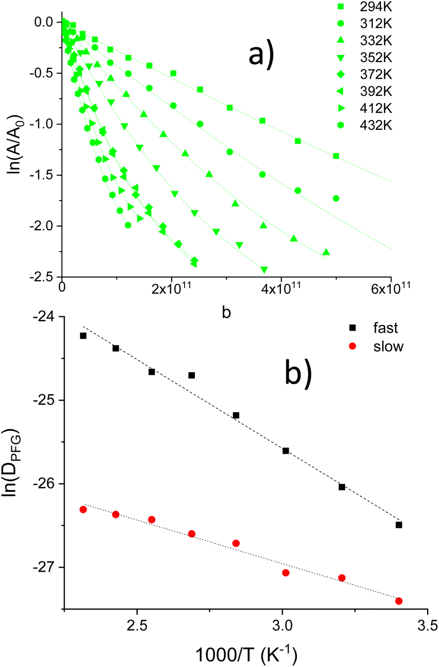 | ||
| Fig. 4 (a) Ln echo attenuations vs. b values in LTAP02-C sample (Δ = 20 ms) in the T = 294–432 K range. Dashed lines were fitted to two exponential contributions, (b) Arrhenius plots of DPFG values deduced for two diffusing species. | ||
 | ||
| Fig. 5 (a) Dependence of ln echo attenuations on b values in the ceramic Li1.4Ti1.6Al0.4(PO4)3 sample. Only linear regions (solid symbols) were considered in determination of DPFG values. (b) Plot of echo signal attenuations (log scale) vs. q(γδg) values. | ||
In Fig. S2,† the attenuation of the echo signal (log scale) is depicted in the q-space, for δ = 2 ms and Δ = 10, 20 and 40 ms (a, b and c, respectively), at different temperatures.
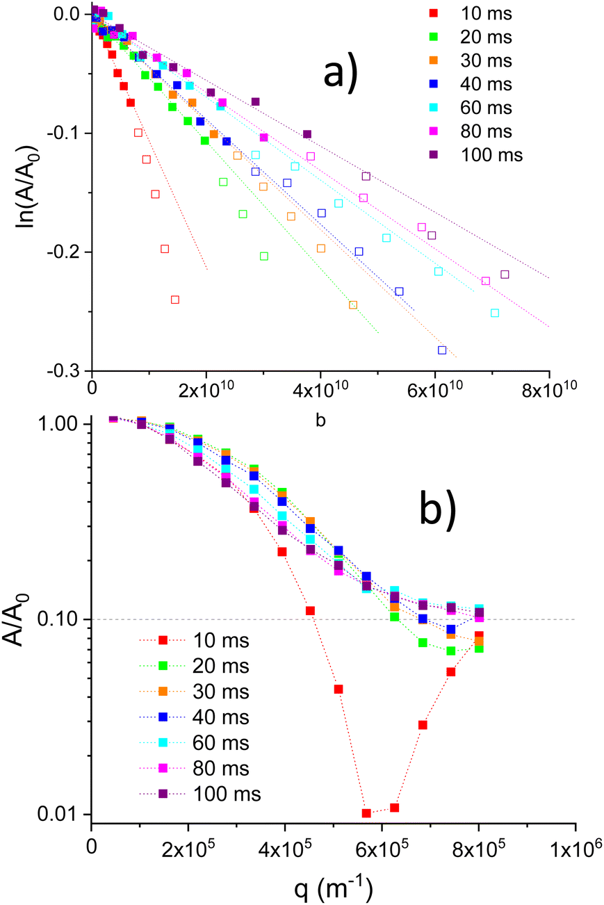
For high gradient values, negative values for attenuation were observed. In order to obtain a A/A0 plot (log scale) vs. q (Fig. 5b), a positive 0.1 shift was applied to attenuation values. A dash line at A/A0 = 0.1 denote the original 0 value. Fig. 5b, illustrates the presence of minima associated with restricted Li motions inside particles (diffraction effects). In Li1.4Ti1.6Al0.4(PO4)3, qmin values deduced from minima, show a shift towards higher q values when Δ values increase (Fig. 5b). From the position of minima, distances Rdif ∼ qmin−1 were deduced, decreasing from 1.7 to 1.3 μm when Δ increases from 10 to 40 ms (Fig. 6b).
 | ||
| Fig. 6 (a) RT dependence of diffusion (DPFG) coefficients and mean square displacements (MSD) on diffusion time (Δ) for the Li1.4Ti1.6Al0.4(PO4)3 sample. (b) Variation of the inverse position of minima, qmin−1, with diffusion Δ times. | ||
Because of the presence of minima detected above q ∼ 6 × 10⁵ m−1 values, only linear lnA/A0 regions (solid symbols) were considered in determinations of DPFG values (Fig. 5a). Deduced diffusion coefficients decrease with the diffusion Δ time (Fig. 6a). For Δ = 10 ms, the diffusion coefficient was near 1.1 × 10⁻¹¹ m2 s−1, but, above 20 ms, DPFG values decrease slowly towards the 3 × 10⁻¹² m2 s−1 value. MSD distances calculated with the expression (6), increase in a monotonous way from 6 × 10⁻¹³ to 1.7 × 10⁻¹² m2 when Δ increases from 10 to 100 ms. For higher Δ values, errors in MSD values increase considerably (Fig. 6a).
Variable temperature measurements (300 to 420 K) were done for Δ = 10, 20, 40 and 80 ms. In Fig. 7a, the (A/A0) vs. q for Δ = 10 ms is plotted, after the positive displacement of the curve at the different temperatures. Diffraction minima shift slightly towards a lower limit q value ∼ 5.7 × 10⁻⁶ m−1, when temperature increase (Fig. 7a), indicating that Rdif increases towards the 1.8 μm value when temperature increases (Fig. 7b). The observed minima is less evident on increasing T, the diffraction effect is strongly affected by the temperature. These results will be discussed later.
 | ||
| Fig. 7 (a) The echo signal attenuation vs. q (m−1) in LTAP04-C (Δ = 10 ms) for different temperatures. (b) Evolution of qmin−1 values with temperature (Δ = 10 ms). | ||
In the determination of diffusion coefficients, only low ln(A/A0) attenuations were again considered; despite the possible existence of a second type of diffusing species. In Fig. 8a the ln attenuation vs. b for Δ = 40 ms is shown. The temperature dependence of DPFG values with the inverse of temperature (Arrhenius plots) is depicted in Fig. 8b. Table S2† summarizes DPFG, MSD and RMSD values for these experiments. From Arrhenius plots, activation energies, deduced for Δ = 20, 40 and 80 ms diffusion times, were deduced (0.11–0.12 eV), indicating the presence of a single activation energy for long-range diffusing species.
 | ||
| Fig. 8 (a) Ln of attenuation vs. b for (Δ = 40 ms) in the temperature range 300–420 K. (b) Arrhenius plots of DPFG values for three diffusion Δ times (20, 40 and 80 ms) in the LTAP04-C sample. | ||
Fig. 9a shows the dependence of DPFG and MSD values on Δ values in LTAP03-SG. In this sample, diffusion coefficients decrease from ∼3 × 10⁻¹² to 3 × 10⁻¹³ m2 s−1 with Δ times. The MSD distances calculated from DPFG coefficients give values near 3 × 10⁻¹³ m2, suggesting the Li confinement inside small particles (∼0.6 μm). The DPFG coefficients and MSD values deduced for LTAP04-SG sample are near those of the LTAP03-SG sample at room temperature. The fast decrease observed in DPFG values with Δ times, indicates that lithium diffusion is strongly restricted in sol–gel samples (see Discussion).
 | ||
| Fig. 9 (a) Dependence of diffusion DPFG coefficients and mean square displacements on Δ values in LTAP03-SG sample. (b) Variation of diffraction distances (qm−1) with Δ values. | ||
Finally, Rdif ∼ qmin−1 distances deduced from echo attenuated minima in LTAP03-SG and LTAP04-SG samples, decrease towards values near 1.1 μm, when diffusion Δ time increase from 10 to 30 ms. The grain diameter deduced by SEM in sol–gel samples was near 300 nm. Table S3† summarizes DPFG, MSD, RMSD and q−1 values for LTAP03-SG and LTAP04-SG samples (Δ = 20 ms).
PFG experiments were also analyzed at increasing temperatures; however, DPFG values practically did not change in both LTAP03-SG and LTAP04-SG samples.
Discussion
Structural model
The Rietveld analysis of neutron diffraction (ND) patterns confirmed the rhombohedral Rc symmetry of LTAP samples. In structural refinements performed on ceramic samples, atom positions, site occupations and thermal factors were deduced in the temperature range 300–500 K. In this analysis, most Al was allocated at octahedral sites of NASICON phases; but, a small part was detected in tetrahedral positions of secondary AlPO4 phases.11,16,26 ND Fourier map differences performed on ceramic samples, indicated that most Li occupy M1 sites, but part of Li occupies M3 sites (near M12 windows) of the NASICON network. As a consequence of the Li increment, the occupation of M3 sites was favoured at expenses of that of M1 sites.
In agreement with structural analyses, 7Li MAS-NMR spectra of LTAP samples, showed an intense signal at 0 ppm, with CQ ∼ 35 kHz and η = 0 parameters, that was ascribed to Li ions allocated at M1 sites.16,18,28 The CQ parameter increased from 35 to 60 kHz as temperature increases, suggesting that Li1 ions shift to more distorted sites.16,29 A deeper analysis of NMR spectra showed the presence of an additional signal at ∼−0.5 ppm that was ascribed to Li ions at M3 sites (Fig. 1). In this case, the absence of quadrupolar interactions, was associated with a higher mobility of lithium.
NMR relaxometry
The allocation of Li at M1 sites favoured the occupation of M12 windows during heating. When unit cell expands, quadrupolar interactions increase considerably as a consequence of the planar coordination of Li ions. The occupation of M3 sites (M2 cavities) was favoured when further Li is incorporated into NASICON phases. In this case, two Li ions are disposed at two opposite triangular windows that surround M1 sites (Li3–Li3 distances ∼ 6.5 Å).11 The formation of Li pairs decreased electrostatic repulsions between Li ions (Li1–Li3 distances ∼ 3.5 Å); however, the unfavourable coordination of Li at M3 sites favours mobility of lithium.The hopping between M1 to M12 and between M12 to M3 sites is responsible for two relaxation mechanisms detected in 1/T1 and 1/T2 plots (Fig. S4†). At the HT 1/T1 maxima (300 K), residence times are ∼1/υ0 ∼ 10−8 s. Taken into account that hopping distance between equivalent sites is ∼6 Å, a self-diffusion coefficient DS ∼ 5 ×10⁻¹² m2 s−1 was estimated.
Pulse field gradient determinations
In the narrow gradient pulse approximation, δ was fixed to 2 ms and Δ increased from 10 to 100 ms.30 From linear ln(A/A0) vs. b plots, diffusion coefficients along the field gradient direction (z-axis) were deduced. In PFG determinations, the low g-values region was used to eliminate diffraction effects in DPFG determinations.27,31In the study of DPFG values, different length scales can be considered:30,32,33 (1) the  distance required for Li spins to dephase 2π radians along the field gradient direction was first analyzed. If we assume g = 2500 gauss cm−1 and Δ = 10 ms, the spin phase change several cycles per μm, what makes possible the cancellation of the magnetization inside particles for a given g value (see next section). (2) In the case of isotropic diffusion along three axes, the distance that diffusing species travel during Δ time, is estimated with the expression
  (3) In small particles a restricted diffusion is produced, what decreases DPFG values when Δ time increases. In the case of spherical particles, structural (LS) lengths were associated with the particle diameter. From the comparison of LS and LD values, three different regions can be considered. When LD < LS, diffusion motions are not restricted (free diffusion); when LD ∼ LS, restriction effects appear, and when LD ≥ LS ions, restriction effects become important, making difficult the analysis of DPFG values.
In compounds with rather low diffusion coefficients it is important to use larger g values to get reliable DPFG values. Also and in order to be close to the short pulse approximation (no diffusion occurs during the gradient pulse duration) δ values should be short as possible. The combination of large g with short δ produces the appearance of artefacts in the attenuation typically at short Δ, that changes the estimated DPFG(Δ) values. Usually these effect enhance the DPFG(Δ) at the shortest Δ. In our results it can be observed that the DPFG (10 ms) values are much larger than the DPFG (20 ms) ones. This important decrease can be related to the existence of eddy currents and/or some phase shift between the gradient pulses due to experimental (hardware) problems34,35 The PFGSTE sequence used in our experiments is good to minimize eddy currents, but maybe some phase shift is unavoidable using this sequence. The existence of diffraction effects in the attenuation curve due to restricted diffusion can also produce the overestimation of DPFG(Δ). The MSD evolution with Δ, see Fig. 6a, is clearly anomalous at short Δ. It should be born in mind that MSD should increase with until reaching the diffusion space limit (particle size). The MSD (10 ms) value is almost the same as MSD (20 ms); this is a clear indication of overestimation of DPFG (10 ms). So for further discussion of restricted diffusion in our samples the DPFG (10 ms) results will not be used, despite it can appear in plots.
In the literature, the PFG technique was used to investigate diffusion coefficients in single Li6.5La3Zr1.5Ta0.5O12 (LLZTO) crystals of 3 × 3 × 30 mm3 dimensions.36 In this work, PFG experiment were done in the free diffusion regime (LD ≪ LS), making unlikely the presence of restriction/diffraction effects.34 In this case, deduced DPFG values were ∼2.5 × 10⁻¹² m2 s−1 at 300 K, not being affected considerably by Δ times (20–100 ms). The activation energy, 0.43 eV, agreed with that deduced from ion conductivity. In this case experimental DPFG ≈ DS.
In the ceramic LTAP02-C sample, diffusion LD distances remain below the crystallites LS size (LD/LS < 1) making the determination of DPFG coefficients reliable. For short Δ times, diffusion coefficients are near DS values deduced by NMR relaxometry, 3 × 10⁻¹² m2 s−1 compared to 5 × 10⁻¹² m2 s−1. In the case LTAP04-C sample DPFG values are lower than that deduced from relaxation measurements. In the latter case, from 1/T1ρ measurements (τc@300 K = 10−7.5 s), DS ≈ 1.14 × 10⁻¹¹ m2 s−1 (ref. 18) compared with DPFG ≈ 5 × 10⁻¹² m2 s−1, see Fig. 6a. In LTAP samples, the increment of lithium increases electrostatic Li–Li repulsions, enhancing Li mobility when going from LTAP02-C to LTAP04-C samples. This makes LD to increase, enhancing restriction effects for similar particle size and Δ times.
When DS values increase or the crystallite size decrease (LTAPO4-C sample), more pronounced restriction effects appear, which causes a faster decrease in DPFG values with diffusion Δ times. In the (LD ∼ LS) regime, DPFG coefficients decrease and MSD distances increase with Δ times towards constant values (Fig. 3b and 6a). For LTAP04-C sample, DPFG and MSD values increase at increasing temperature, suggesting that restriction effects are stronger but not still dominant.
In smaller sol–gel particles, LD ≥ LS, restriction effects increase, considerably, making that DPFG coefficients decrease faster with Δ, and MSD values become almost constant. Taken into account differences observed in analyzed samples, a parallel discussion of DPFG and RMSD values must be undertaken in different analyzed samples.
In literature, several models have been proposed to explain diffusion coefficients for restricted motions. The observed decrease of DPFG coefficients with Δ values can be described, for isolated spherical particles, with the Mitra expression:37
 | (7) |
Another simple approximation has been proposed in ref. 31; where, authors propose a simplified equation for diffusion coefficients in isolated spherical particles
 | (8) |
DPFG decrease in a linear way with Δ. In this regime, diffusion coefficients are given by the expression DR = a2/5Δ, that affords information about the mean particle volume.
In Fig. 10, three regions are resolved in logDPFG (Δ) vs. Δ plots. In the LTAP04-C sample (red lines), it was concluded that DPFG are near DS values deduced for short Δ values (Δ < 0.01 s). In the intermediate range (0.01 s < Δ < 0.1 s), DPFG decreases as a consequence of restriction effects. Finally for long Δ values (Δ > 0.1 s), where restrictions effects are important, logDPFG values decrease in a linear way with Δ values.
 | ||
| Fig. 10 Dependence of experimental PFG DPFG values on diffusion Δ times. These values were reproduced with eqn (8), solid lines. The symbols notation and experimental errors are included. The values considered in this analysis are given in Table 1. DPFG (10 ms) values are not used in the fitting of the restricted diffusion model. | ||
The fit of DPFG(Δ) values with eqn (8) affords an estimation of DS values in ceramic samples, that are not strongly affected by restrictions. In the case of sol–gel samples, where Li motion is restricted (DSΔ/a2 ≥ 1), DS can only estimated in an approximated way. In this case, DPFG values must be bigger than a2/0.02 ∼ 1 × 10⁻¹¹ m2 s−1, that were near of that deduced for short Δ = 0.02 s values.
From the analysis of DPFG values (Table 1), it can be concluded that DS values are high in all the LTAP samples (DS > 3 10−12 m2 s−1). The measured DPFG decrease faster in presence of restricted motions. Restriction effects are bigger in LTAP04-C than in LTAP02-C, but much lower than in sol–gel LTAP03-SG and LTAP04-SG samples. To reduce restriction effects, the powders sintering could be improved, increasing the particle size and making more efficient the connection between grains.
| Sample | DS (m2 s−1) | a (m) |
|---|---|---|
| LTAP02-C | 3.2 × 10⁻¹² | 1.81 × 10⁻⁶ |
| LTAP04-C | 6.5 × 10⁻¹² | 1.45 × 10⁻⁶ |
| LTAP03-SG | >1 × 10⁻¹¹ | 0.45 × 10⁻⁶ |
| LTAP04-SG | >1 × 10⁻¹¹ | 0.47 × 10⁻⁶ |
In LTAP samples, the increment of the Li content increases electrostatic Li–Li repulsions, favouring the occupation of M3 sites and the creation of M1 vacancies, which increases lithium mobility. Above 300 K, the Li1.2Ti1.7Al0.2(PO4)3 (LTAP02-C) sample showed the presence of two diffusion species in PFG determinations, with activation energies: 0.18 and 0.09 eV (Fig. 4b). These two values were previously ascribed to the presence of core–shell structures.21 In LTAP04-C sample, two populations could not be deduced because the presence of diffraction effects. In the case of the LTAP04-C sample, activation energy decrease to 0.12 eV. In two analyzed ceramics, activation energy deduced from DPFG values, 0.18 and 0.12 eV, that were not far from those deduced by HT conductivity, (0.22 eV) when correlation effects strongly diminished. To deduce structural reasons that increase Li mobility, Density Functional Theory (DFT) and Molecular Dynamics (MD) simulations should be used.28,29,38
Diffraction effects
During application of pulse field gradients, the magnetic field is given by B0 + g(z) inside particles, making that different Li ions display different resonance frequencies. From this fact the orientation of magnetic spins change along the g direction, affecting the intensity of the resulting echo magnetization. When the spin de-phasing along the particles diameter covers n-times the [0,2π] interval, the resultant magnetization could disappear as a consequence of the pulse field gradient application. This observation results from the space calibration with gradient pulses; that makes to decrease considerably the echo signal intensity at specific qm(γgδ) values, when qmRdif ∼ 1 (diffraction effects).39,40 However, spin memory is preserved in PFG experiments, making that magnetization be recovered for higher q > qm values.The position and importance of minima must also depend on the size and shape distributions of particles is solid electrolyte powder. This influence has not been taken into account in the present work. Where just average particle size and spherical particles were considered. In analyzed samples, the position of minima changed with temperature, indicating that distances over which magnetization is averaged, changes. In particular, Rdif values increase with temperature, making that the position of minima shifts towards lower q values, approaching in an asymptotic way to specific values that must be related with the crystallites size distribution (Fig. 5b and 7a) in sample.
At this point, it is interesting to analyze MSD and Rdif values deduced for different Δ values. To compare equivalent parameters, root mean square distances (RMSD) were deduced from DPFG values, with the expression
 | (9) |
In Fig. 2, SEM micrographs allowed an estimation of the averaged crystallites size. In this analysis, only smaller particles (more abundant) have been considered. In ceramic samples, the particles size (diameter) was ∼2 μm in LTAP02-C and ∼1.5 μm in LTAP04-C, but in sol–gel samples, the particles size were ∼300 and 400 nm in LTAP03-SG and LTAP04-SG samples respectively. The particle radius obtained at room temperature from de application of eqn (8) to the DPFG(Δ) values is in good agreement with the results of Rdif at RT in the LTAP04-C sample ≈ 1.5 μm, see Fig. 7b. The result obtained from PFG is related to the 〈a〉V mean radius in the volumetric distribution, so larger particles should have a weight in this value even if they are much less abundant. The values deduced at room temperature, from the fit to eqn (8) and Rdif values are much different for the sol–gel samples. The calculated value (Table 2) are closer to the value deduced form the SEM micrographs, but Rdif values differ considerably.
| Sample | T (K) | bσbulk(T) (S cm−1) | DS (m2 s−1) | N(T) | N(T)a |
|---|---|---|---|---|---|
| a N(T) calculated from extrapolated σbulk(T) at 103 Hz.b From ref. 21. | |||||
| LTAP02-C | 290 | 0.00214 | 3.2 × 10⁻¹² | 6.24 × 10²¹ | 1.57 × 10²¹ |
| LTAP04-C | 293 | 0.0025 | 6.5 × 10⁻¹² | 3.64 × 10²¹ | 9.12 × 10²⁰ |
| LTAP04-C | 300 | 0.00327 | 8.2 × 10⁻¹² | 3.87 × 10²¹ | 9.72 × 10²⁰ |
| LTAP04-C | 330 | 0.00758 | 1.4 × 10⁻¹¹ | 5.79 × 10²¹ | 1.44 × 10²¹ |
| LTAP04-C | 360 | 0.01415 | 2.2 × 10⁻¹¹ | 7.50 × 10²¹ | 1.87 × 10²¹ |
| LTAP04-C | 390 | 0.02528 | 3.4 × 10⁻¹¹ | 9.42 × 10²¹ | 2.35 × 10²¹ |
| LTAP04-C | 420 | 0.04104 | 4.2 × 10⁻¹¹ | 1.32 × 10²² | 3.31 × 10²¹ |
Taken into account that this comparison has been performed at room temperature, the analysis was extended to higher temperatures.
In Fig. 11, a comparison of Rdif and RMSD distances is performed for different temperatures. In the ceramic LTAP04C sample, Rdif distances (qm−1) increases slowly from 1.5 to 1.7 μm, but RMSD distances increase from 1.2 to 1.6 μm in the 300–420 K temperature range. In this figure, Rdif and RMSD values extrapolated at high temperatures approach the value deduced by SEM micrographs, 1.5 μm. In the case of the LTAP02-C sample, only the temperature dependence of RMSD values could be deduced. The absence of important restrictions make that RMSD values increase in a monotonous way with temperature, approaching the crystallite size, 1.5 μm, at the highest temperatures. In the case of sol–gel samples, only SEM and Rdif values at 300 K (∼0.4 and 1 μm) could be deduced.
 | ||
| Fig. 11 Variation of Rdif distances (triangles) with temperature for the ceramic LTAP04 sample. In this figure, RMSD values obtained for Δ = 10 and 20 ms, are denoted by squares and circles (RMSD1 and RMSD2). Average grain size deduced by SEM are denoted by horizontal segments (—). In this plot results obtained in ceramic LTAP02 and sol–gel LTAPSG samples are included. | ||
In LTAP04-C, Rdif ∼ qm−1 values changed from 1.6 to 1.3 μm when going from Δ = 20 to Δ = 40 ms. These values are near those deduced from DPFG(Δ) values measured at increasing temperatures, SEM microscopy 1.5 μm and particle radius deduced by the restricted diffusion model, Table 1. In sol–gel samples, Rdif values deduced from minima vary from 1.5 to 1.2 μm when going from Δ = 10 to 30 ms in LTAP03-SG and from 1.8 to 1.3 μm when going from Δ = 10 to 30 ms in LTAP04-SG. Differences detected with respect SEM values, and model results in Table 1, suggest that connectivity between grains is improved at the highest temperatures, as a consequence of the fused glassy phases formed (Fig. 2).
The dependence of the minima position and RMSD values on Δ times and temperature is similar to that detected on DPFG coefficients, suggesting that kinetics parameters are not strictly separated from geometrical ones. The agreement in the deduced Rdif value among the sol–gel samples and the LTAP04-C one make that these results should be regarded with care, specially the evolution of the diffraction effect with Δ. In the echo attenuation of spins trapped in an spherical inclusion (particle) with perfectly reflecting boundaries the diffraction effect is stronger in attenuation magnitude for larger Δ. Short δ values also increases the diffraction attenuation. If magnetization relaxation is present in the particle surface the effect is to reduce the diffraction effect on increasing Δ, but with an effective narrowing of the particle.39,41 The diffraction effect due to the phase shift between gradient pulses artefact, can explain the observed phenomena and the evolution of the echo attenuation with Δ. Further experiments are necessary to elucidate the origin of the diffraction effect. A similar behaviour of qm−1 with Δ was reported in LAGP compounds,25 where, authors related this behaviour to the existence of faster Li species that diffuses to longer distances before reaching boundaries.
Charge carrier concentration
Li1+xTi2−xAlx(PO4)3 LTAP ceramic compounds are among the best lithium conductors. In this series, ion conductivity increased considerably from x = 0 to x = 0.2, passing through a broad maximum (5 × 10⁻³ S cm−1 at RT) at x = 0.4 and decreasing above this composition.42 In sol–gel samples, RT bulk conductivity increased slowly up to 7.0 × 10⁻³ S cm−1 in x = 0.4 sample, and then decreases.26Ion-conductivity is related to the conductivity diffusion coefficient (Dσ) by the expression:
| σdc(T) = [e2N/kT]Dσ(T) | (10) |
The calculated N values deduced from eqn (10) for sample LTAP04-C as a function of temperature are included in Table 2, showing an increase of the charge carrier concentration with temperature. The activation energy deduced for the bulk conductivity at analyzed temperatures is 0.24 eV.21 The activation energy for the Li diffusion process, calculated DS(T), is 0.15 eV (Fig. S2b†), so the increment of N with temperature can be related to the activated charge carrier formation. The increment of the charge carrier number N, is a factor four in the analyzed temperature range (300–430 K).
The expected concentrations of Li in LTAP02-C and LTAP04-C are close to 5.5 × 1021 cm−3 and 6.4 × 1021 cm−3 respectively. These values are smaller than deduced from N values calculated from DS(T) and “bulk” dc conductivity. At RT for LTAP02-C and at T > 330 K for LTAP04-C, see Table 2. As, N values are the result of σ/DS ratio, an error in the determination of any of two magnitudes has a strong effect. If “bulk” conductivity is assumed correct, these results support the idea that deduced DS(T) are smaller than true ones. However, if “bulk” dc conductivity, defined at the frequency range 107 to 109 Hz, is not appropriate, N values should not make sense.
At this point it is interesting to comment that in fast solid electrolytes related to the β′′ Al2O3 structure, it is not possible to find a true dc plateau in the log(σ(ω)) vs. log(ω) plots. A slope close to n = 0.15 instead of ≈ 0 has been found in single crystals of these solid-electrolytes.44 Despite the influence of the Maxwell–Wagner polarization due to the electrode blocking, this effect should be mainly associated with the sub-diffusive nature of ion transport. In the case of the LTAP phases, the dc “plateau” presented a slope in the range 0.15 < n < 0.11, see Fig. 8 in ref. 21. The compositional heterogeneity seems to be behind this lack of pure dc “plateau”.41,42 In LTAP samples, a clustering of Al has been deduced from the analysis of 31P spectra, concluding the existence of external regions (shell) with higher Al concentration than inside particles (core).26 In other fast electrolytes ceramics like La0.6Li0.2TiO3 and La0.5Li0.16Sr0.16TiO3 the slope in the dc “plateau” is much lower (n = 0.05), see Fig. 7 and 9 of ref. 45.
In PFG experiments performed here DS values deduced by eqn (8) in LTAP02-C not differ much from DS ≈ 5 × 10⁻¹² m2 s−1 obtained from relaxation measurements, see Fig. S2a and 10.† In the case of LTAP04-C the difference is larger (from 6.5 × 10⁻¹² m2 s−1 to 1.14 × 10⁻¹¹ m2 s−1). On the other hand, the absence of a true “bulk” conductivity plateau related to a sub-diffusive behaviour implies a variation of sample conductivity with frequency, decreasing in value on decreasing frequency. In the calculation of DS with the simple model of eqn (8) no sub-diffusion is considered, so a correction of the “bulk” conductivity value to a time measuring window closer to that used in the PFG experiment can be implemented. If the log(σ(ω)) values are extrapolated to 103 Hz for each temperature, it is possible to take conductivity value at the same time scale that used in DS(T) determinations. In this case, N(T) values deduced from comparison of DS(T) and σdc conductivity are better justified. This correction produces a reduction of ∼0.25 times of the “bulk” conductivity for 4 order of magnitude of frequency reduction. Using the extrapolated value, the concentration of charge carriers N is reduced in the same amount, see Table 2. Using this approximation the charge carrier concentration is below the nominal one in the analyzed temperature range. From these results, an enthalpy of carriers formation Hf = 0.1 eV is obtained; adding up both enthalpies (Hf + HDS) = 0.25 eV, resulting values are near activation energy deduced from the “bulk” conductivity, 0.24 eV.21
The possible sub-diffusion deduced in the LTAP can have important implication for the application of these materials in electrochemical devices.
As the majority of the crystalline solid electrolytes are obtained in powder form, special effort must be done in determination of the powder microstructure, because the importance of the diffusion space (grain size) on diffusion coefficients. In particular, the presence of core–shell effects, internal barriers46 or compositional heterogeneities limits the long range diffusion of lithium. The study of powder samples with a narrow distribution of grain sizes and rather large crystallites will permit to better model experimental results. From this fact, the use of the powerful NMR PFG technique will permit to obtain good estimations of intrinsic lithium diffusion coefficients. In all cases, this study will afford important information for the optimization of solid electrolytes.
Conclusions
Extended motions were investigated with the NMR-PFG technique in LTAP samples prepared by sol–gel and ceramic routes. In PFG experiments, time scales differ considerably from those involved in 1/T2 and 1/T1 measurements, however, DPFG values deduced for short Δ times are in the range of those deduced by NMR relaxometry. The diffusion coefficients measured in two ceramic samples confirm the increment of conductivity produced at increasing Al/Li contents in LTAP samples.Special care must be taken to avoid experimental artifacts that can overestimate the DPFG(Δ) values at short Δ, by a fine selection of the PFGSTE sequence and experimental parameters.
In all analyzed samples, diffusion coefficients measured at short Δ times are between 5 × 10⁻¹² and 1 × 10⁻¹¹ m2 s−1. At increasing Δ times, diffusion coefficients decrease due to restriction. In ceramic LTAP02-C sample, Li diffusion is less restricted than in LTAP04-C sample, where DPFG values increase and particle size decreases. The analysis of DPFG coefficients in sol–gel LTAP03-SG and LTAP04-SG samples, shows strong restriction effects that considerably reduce DPFG values when Δ times increase, suggesting that Li diffusion is strongly restricted when the LTAP particles are smaller than 1 μm.
Reliable DS values can be deduced from experimental DPFG(Δ)values by using simple models that take into account the distribution of particle sizes in the solid electrolyte powder.
From diffusion measurements performed at increasing temperatures, particle size was estimated from MSD and qm−1 values. To reduce restriction effects, denser samples with large crystallites should be prepared.
The estimation of charge carrier concentration form deduced DS values and “bulk” dc conductivity, supports the possibility of sub-diffusion in the Li transport along the LTAP crystallites.
In future works, the PFG technique will permit a deeper understanding of transport properties in fast ionic conductors and the influence of the preparation conditions for their optimization.
Conflicts of interest
There are no conflicts to declare.Acknowledgements
Authors thank the Spanish Agency MINECO (project PID2019-106662RB-C42, MAT2016-78362-C4-2R) and the Regional Agency CAM (project S2013/MIT-2753), M-Era-Net 2016/PCIN-110-2017 for financial support.Notes and references
- X. Xu, Z. Wen, X. Yang, J. Zhang and Z. Gu, Solid State Ionics, 2006, 177, 2611 CrossRef CAS.
- N. Anantharamulu, K. Koteswara Rao, G. Rambabu, B. Vijaya Kumar, V. Radha and M. Vithal, J. Mater. Sci., 2011, 46, 2821 CrossRef CAS.
- J. B. Goodenough, H. Y. P. Hong and J. A. Kafalas, Mater. Res. Bull., 1976, 11, 203 CrossRef CAS.
- M. Alami, R. Brochu, J. L. Soubeyroux, P. Graverau, G. Le Flem and P. Hagenmuller, J. Solid State Chem., 1991, 90, 185 CrossRef CAS.
- D. Tran Qui, S. Hamdoune, J. L. Soubeyroux and E. J. Prince, J. Solid State Chem., 1988, 72, 309 CrossRef.
- E. Morin, J. Angenault, J. C. Couturier, M. Quarton, H. He and J. Klinowski, Eur. J. Solid State Inorg. Chem., 1997, 34, 947 CAS.
- E. R. Losilla, M. A. G. Aranda, M. Martinez-Lara and S. Bruque, Chem. Mater., 1997, 9, 1678 CrossRef CAS.
- M. Catti, S. Stramare and R. Ibberson, Solid State Ionics, 1999, 123, 173 CrossRef CAS.
- H. Aono, E. Sugimoto, Y. Sadaoka, N. Imanaka and G.-Y. Adachi, J. Electrochem. Soc., 1990, 137, 1023 CrossRef CAS.
- K. Arbi, J. M. Rojo and J. Sanz, J. Eur. Ceram. Soc., 2007, 27, 4215 CrossRef CAS.
- K. Arbi, M. Hoelzel, A. Kuhn, F. García-Alvarado and J. Sanz, Inorg. Chem., 2013, 52, 9290 CrossRef CAS PubMed.
- M. Monchack, T. Hupfer, A. Senyshyn, H. Boysen, D. Chernyshov, T. Hansen, K. G. Schell, E. C. Bucharsky, M. J. Hoffmann and H. Ehrenberg, Inorg. Chem., 2016, 55, 2941 CrossRef PubMed.
- Y. K. Shin, M. Y. Sengul, A. S. M. Jonayat, W. Lee, E. D. Gomez, C. A. Randall and A. C. T. van Duin, Phys. Chem. Chem. Phys., 2018, 20(34), 22134–22147, 10.1039/C8CP03586E.
- K. Arbi, S. Mandal, J. M. Rojo and J. Sanz, Chem. Mater., 2002, 14, 1091 CrossRef CAS.
- J. Emery, T. Salkus, A. Abramova, M. Barré and A. Orliukas, J. Phys. Chem. C, 2016, 120, 26173 CrossRef CAS.
- K. Arbi, M. Tabellout, M. G. Lazarraga, J. M. Rojo and J. Sanz, Phys. Rev. B: Condens. Matter Mater. Phys., 2005, 72, 094302 CrossRef.
- N. V. Kosova, E. T. Devyatkina, A. P. Stepanov and A. L. Buzlukov, Ionics, 2008, 14, 303 CrossRef CAS.
- C. Vinod Chandran, S. Pristat, E. Witt, F. Tirtz and P. Heitjans, J. Phys. Chem. C, 2016, 120, 8436–8442 CrossRef.
- K. Arbi, M. A. París and J. Sanz, Dalton Trans., 2011, 10195 RSC.
- S. Breuer, D. Prutsch, Q. Ma, V. Epp, F. Preishuber-Pflugl, F. Tietz and M. Wilkening, J. Mater. Chem. A, 2015, 3, 21343 RSC.
- K. Arbi, W. Bucheli, R. Jiménez and J. Sanz, J. Eur. Ceram. Soc., 2015, 35, 1477–1484 CrossRef CAS.
- J. E. Tanner and E. O. Stejskal, J. Chem. Phys., 1968, 49, 1768–1777 CrossRef CAS.
- J. E. Tanner, J. Chem. Phys., 1970, 52, 2523–2536 CrossRef CAS.
- V. Epp, Q. Ma, E.-M. Hammer, F. Tietzcd and M. Wilkening, Phys. Chem. Chem. Phys., 2015, 17, 32115 RSC.
- K. Hayamizu and S. Seki, Phys. Chem. Chem. Phys., 2017, 19, 23483 RSC.
- R. Jiménez, I. sobrados, S. Martínez-Chaparro, N. Criado, B. Perea and J. Sanz, J. Alloys Compd., 2020, 844, 156051 CrossRef.
- J. Kärger, M. Avramovska, D. Freude, J. Haase, S. Hwang and R. Valiullin, Adsorption, 2021, 27, 453–484 CrossRef.
- J. Emery, T. Salkus and M. Barré, J. Phys. Chem. C, 2016, 120, 26235 CrossRef CAS.
- B. Lang, B. Ziebarth and C. Elsässer, Chem. Mater., 2015, 27, 5040 CrossRef CAS.
- M. E. Hayden, G. Archibald, K. M. Gilbert and C. Lei, J. Magn. Reson., 2004, 169, 313–322 CrossRef CAS PubMed.
- A. Guillermo and M. Bardet, Anal. Chem., 2007, 79(17), 6718–6728 CrossRef CAS PubMed.
- M. D. Hürlimann, K. G. Helmer, T. M. de Swiet and P. N. Sen, J. Magn. Reson., Ser. A, 1995, 113, 260–264 CrossRef.
- D. S. Grebenkov, N. Moutal and D. S. Grebenkov, J. Magn. Reson., 2020, 320, 106836 CrossRef PubMed.
- K. S. Han, J. David Bazak, Y. Chen, T. R. Graham, N. M. Washton, J. Z. Hu, V. Murugesan and K. T. Mueller, Chem. Mater., 2021, 33(22), 8562–8590 CrossRef CAS.
- W. S. Price, K. Hayamizu, H. Ide and Y. Arata, J. Magn. Reson., 1999, 139, 205–212 CrossRef CAS PubMed.
- A. Dorai, N. Kuwata, R. Takekawa, J. Kawamura, K. Kataoka and J. Akimoto, Solid State Ionics, 2018, 327, 18–26 CrossRef CAS.
- P. P. Mitra, Phys. Rev. B, 1993, 47, 8565–8574 CrossRef PubMed.
- V. Diez-Gómez, P. L. de Andrés and J. Sanz, ChemSusChem, 2020, 13–5, 1027–1036 CrossRef PubMed.
- S. L. Cod and P. T. Callaghan, J. Magn. Reson., 2199, 132, 358–372 Search PubMed.
- P. T. Callaghan, S. L. Cod and J. D. Seymour, Concepts in Magnetic Resonance, John Wiley & Sons, Inc., 1999, vol. 11, ch. 4, pp. 181–202, CCC 1043-7347r99r040181-22 Search PubMed.
- M. D. Hürlimann, T. M. de Swiet and P. N. Sen, J. Non-Cryst. Solids, 1995, 182, 198–205 CrossRef.
- D. Rettenwander, A. Welzl, S. Pristat, F. Tietz, S. Taibl, G. J. Redhammer and J. Fleig, J. Mater. Chem. A, 2016, 4, 1506 RSC.
- G. E. Murch, Solid State Ion., 1982, 7, 177–198 CrossRef CAS.
- O. Kamishima, Y. Iwai and J. Kawamura, Solid State Ionics, 2015, 281, 89–95 CrossRef CAS.
- W. Bucheli, R. Jiménez and J. Sanz, Solid State Ionics, 2012, 227, 113–118 CrossRef CAS.
- S. Vasenkov and J. Kärger, Microporous Mesoporous Mater., 2002, 55, 139–145 CrossRef CAS.
Footnote |
| † Electronic supplementary information (ESI) available. See DOI: https://doi.org/10.1039/d3ra02094k |
| This journal is © The Royal Society of Chemistry 2023 |