 Open Access Article
Synergistic effect of porous carbon shell confinement and catalytic conversion of nickel nanoparticle cores for improved lithium–sulfur batteries†
Liu Jianminga,
Zhang Jin *a,
Jiang Shanga and
Zhao Jianguo*ab
aEngineering Research Center of Coal-based Ecological Carbon Sequestration Technology of the Ministry of Education, Shanxi Datong University, Datong, 037009, China. E-mail: zhangjing8014484@163.com
bResearch Institute of Shaoxing, Shanghai University, Shaoxing, 312000, China
First published on 25th April 2023
Abstract
Lithium–sulfur batteries (LSBs) are some of the most promising energy storage systems to break the ceiling of Li-ion batteries. However, the notorious shuttle effect and slow redox kinetics give rise to low sulfur utilization and discharge capacity, poor rate performance, and fast capacity decay. It is proved that the reasonable design of the electrocatalyst is one of the important ways to improve the electrochemical performance of LSBs. Here, a core–shell structure with gradient adsorption capacity for reactants and sulfur products was designed. The Ni nanoparticles core coated with graphite carbon shell was prepared by one-step pyrolysis of Ni-MOF precursors. The design takes advantage of the principle that the adsorption capacity decreases from the core to the shell, and the Ni core with strong adsorption capacity is easy to attract and capture soluble lithium polysulfide (LiPS) during the discharge/charging process. This trapping mechanism prevents the diffusion of LiPSs to the outer shell and effectively inhibits the shuttle effect. In addition, the Ni nanoparticles within the porous carbon, as the active center, expose most of the inherent active sites to the surface area, thus achieving a rapid transformation of LiPSs, significantly reducing the reaction polarization, and improving the cyclic stability and reaction kinetics of LSB. Therefore, the S/Ni@PC composites exhibited excellent cycle stability (a capacity of 417.4 mA h g−1 for 500 cycles at 1C with a fading rate of 0.11%) and outstanding rate performance (1014.6 mA h g−1 at 2C). This study provides a promising design solution of Ni nanoparticles embedded in porous carbon for high-performance, safe and reliable LSB.
1 Introduction
Currently, the theoretical capacity of traditional lithium-ion batteries is limited and it is difficult to meet the demand, especially in large-scale and electric transportation applications.1 Therefore, the next generation of secondary batteries with higher theoretical energy density, lower cost, and longer cycle life is urgently needed.2 Lithium–sulfur batteries (LSBs) have been considered promising energy storage devices due to their high theoretical capacity and energy density, as well as their abundant sulfur storage.3 However, there are still some inherent major obstacles, such as the low electron/ionic conductivity of sulfur,4 rapid expansion (≈80%) in the charge–discharge process,5 and shuttle effect of soluble intermediates in electrochemical reactions.6–8 These problems inevitably lead to low sulfur utilization rate, severe structural instability, limited capacity, rapid capacity decay, poor coulomb efficiency and so on.4–8To handle these challenges, various carbon/sulfur composites, such as nanostructured porous conducting carbon (e.g., Micro/mesoporous carbon, carbon nanotubes (CNTS), graphene, activated carbon),9–13 have been paid close attention by improving electrode conductivity, providing fast ion/electron transport paths and capturing polysulfide via physical domain. For instance, Nazar et al.9 reported a simple and widely available method for encapsulating sulfur into the porous structure of ordered mesoporous carbon (CMK-3) to provide both electrical contacts with sulfur and adequate controlled porosity for trapping polysulfides species. The nanostructured composite had an initial capacity of up to 1320 mA h g−1 and excellent cycling performance. But the conversion of LiPS is kinetically sluggish due to the weak affinity between the non-polar carbon material and the polar sulfur material, which inevitably brings about severe capacity degradation.14 Therefore, it is put forward to introduce an effective catalyst for LiPSs conversion to significantly reduce the shuttle effect and improve the conversion kinetics of LiPSs. Metallic nanocatalysts (e.g., Ni,15 Co,16 and Fe17) with high conductivity utilized in sulfur cathodes have a considerable affinity and catalytic capability for polysulfide conversion. Meanwhile, uniformly dispersed metal nanoparticles can be also used as LiPSs anchoring centers and electrocatalytic active sites to obtain satisfactory LSBs performance.18 Therefore, the incorporation of metal nanoparticles into the conductive porous carbon skeleton is considered to be an effective integration of their advantages to obtain an ideal sulfur material.
As far as we know, the metal–organic framework (MOF) is composed of metal ions or clusters connected with organic ligands through coordination bonds. MOFs possess richer pore structures and larger specific surface areas than porous carbon materials.19 Moreover, due to their inherent porous structure and adjustable chemical composition, MOFs have been used as precursors/templates to prepare metal-porous carbon nanostructures with specific morphology and composition.20–23 The presence of polar metal species can effectively trap polysulfide and catalyze the redox reaction of sulfur species by providing some active sites. And their high conductivity and ionic conductivity provide fast lithium ion and electron transport paths.
Here, we design a core–shell structure in which the core of Ni nanoparticles is encased by a graphite-carbon shell with an adsorption gradient (Fig. 1). Among them, the carbon skeleton and the derived porous carbon are together handled to construct a conductive network and sufficient ion pathways. The Ni nanoparticles cores with strong LiPS adsorption ability attract and capture soluble LiPS during the discharge/charge process, which significantly prevents LiPSs from diffusing to the outer shell and effectively inhibits the shuttle effect. The construction of interconnected macroscopic/mesopore channels effectively alleviates the accumulation of metal Ni nanoparticles and exposes most of the inherent active sites to the surface region, while the transition metal interface ensures rapid electron transfer, thus achieving efficient capture of lithium polysulfide (LiPSs) and rapid conversion during electrochemical processes. Based on these synergistic effects, the S/Ni@PC cathodes exhibit excellent electrochemical performance with a low capacity decay rate of 0.11% for 500 cycles at 1C and a high capacity of 1014.6 mA h g−1 at 2C.
2 Experimental
2.1 Material preparation
![[thin space (1/6-em)]](https://www.rsc.org/images/entities/char_2009.gif) :
:![[thin space (1/6-em)]](https://www.rsc.org/images/entities/char_2009.gif) 7 and ball-milled for 2 h. The S/Ni@PC and S/SP complexes were then obtained at 155 °C for 10 h.
7 and ball-milled for 2 h. The S/Ni@PC and S/SP complexes were then obtained at 155 °C for 10 h.![[thin space (1/6-em)]](https://www.rsc.org/images/entities/char_2009.gif) :
:![[thin space (1/6-em)]](https://www.rsc.org/images/entities/char_2009.gif) 2
2![[thin space (1/6-em)]](https://www.rsc.org/images/entities/char_2009.gif) :
:![[thin space (1/6-em)]](https://www.rsc.org/images/entities/char_2009.gif) 1. Then, the formed slurries are pasted onto the aluminum foils and allowed to dry overnight in a vacuum at 60 °C. The mass loading of the sulfur specie was ∼1.0 mg cm−2.
1. Then, the formed slurries are pasted onto the aluminum foils and allowed to dry overnight in a vacuum at 60 °C. The mass loading of the sulfur specie was ∼1.0 mg cm−2.2.2 Physical characterizations
X-ray diffraction (XRD) patterns were performed on a RINT2000 apparatus (Rigaku). The Scanning Electron Microscopy (SEM, JSM-6700E) and Transmission Electron Microscope (TEM, JEM-2010) were operated to analyze the morphology of the structure. Thermogravimetric analysis (TGA, HCT-1) was used to assess the sulfur loading in the composites at a heating rate of 10 °C min−1 in N2 atmospheres.2.3 Electrochemical measurements
The CR2025 coin-type cells were assembled in an argon-filled glovebox (M Braun), where 1 M LiTFSI dissolved in DOL/DME (1![[thin space (1/6-em)]](https://www.rsc.org/images/entities/char_2009.gif) :
:![[thin space (1/6-em)]](https://www.rsc.org/images/entities/char_2009.gif) 1, vol) with 1 wt% LiNO3, Celgard 2400 polypropylene, lithium plate, and S/Ni@PC or S/SP were served as electrolytes, separator, anode, and cathodes, respectively. The cells were aged for 12 h prior to electrochemical measurements to guarantee a completely wetted electrode. A program-controlled test system (LAND CT2001A) was used to carry out the galvanostatic charge/discharge tests in the range of 1.6 to 2.8 V at room temperature. On an Autolab electrochemical workstation (PGSTAT302N), cyclic voltammetry measurements were measured from 1.6 to 2.8 V at 0.1 mV s−1. If not specified, the loading mass of sulfur in the electrode was ∼1.0 mg cm−2, and the electrolyte/sulfur ratio (E/S) is 25 μL mg−1.
1, vol) with 1 wt% LiNO3, Celgard 2400 polypropylene, lithium plate, and S/Ni@PC or S/SP were served as electrolytes, separator, anode, and cathodes, respectively. The cells were aged for 12 h prior to electrochemical measurements to guarantee a completely wetted electrode. A program-controlled test system (LAND CT2001A) was used to carry out the galvanostatic charge/discharge tests in the range of 1.6 to 2.8 V at room temperature. On an Autolab electrochemical workstation (PGSTAT302N), cyclic voltammetry measurements were measured from 1.6 to 2.8 V at 0.1 mV s−1. If not specified, the loading mass of sulfur in the electrode was ∼1.0 mg cm−2, and the electrolyte/sulfur ratio (E/S) is 25 μL mg−1.
2.4 Symmetric cell assembly
The identical working and counter electrodes of Ni@PC and SP were assembled with 0.2 M Li2S6 (50 μL) electrolyte, respectively. The CV measurements were carried out on the electrochemical workstation with scanning speeds from 1 to 30 mV s−1.2.5 Adsorption tests
Ni@PC (10 mg) or SP (10 mg) and 3 mL of diluted Li2S6 solution (∼3 mM) were put into a transparent vial and aged 24 h to observe the change of liquid color.3 Results and discussion
The morphology and composition of the prepared samples are detected by XRD and microscopy. The uniform spherical Ni-MOF particles with an average diameter of ∼500 nm are shown in Fig. 2(a and b). After pyrolysis at high temperatures, the typical diffraction peaks of nickel are found at 44.5°, 51.8°, and 76.3°, indicating that Ni2+ in Ni-MOF is reduced to metal Ni.18 And another small diffraction peak of ∼26° is attributed to the (002) crystal surface of graphitic carbon (Fig. 2c). The average particle size of Ni nanoparticles calculated by the Scherrer formula is ∼25 nm. A rough surface is formed because many smaller Ni nanoparticles are embedded inside the carbon sphere, while the original skeleton of the MOF is preserved (Fig. 2d and e). The TEM images (Fig. 2d and e) reveal that the highly dispersed Ni nanoparticles with average diameters of ∼25 nm (ranging from ∼10 to ∼50 nm), which is match with the XRD results. And the Ni core is coated with graphitic carbon (Fig. 2f), indicating the formation of a core–shell structure. The lattice spacing of 0.2 nm is consistent with Ni(111), indicating the presence of metallic Ni nanoparticles.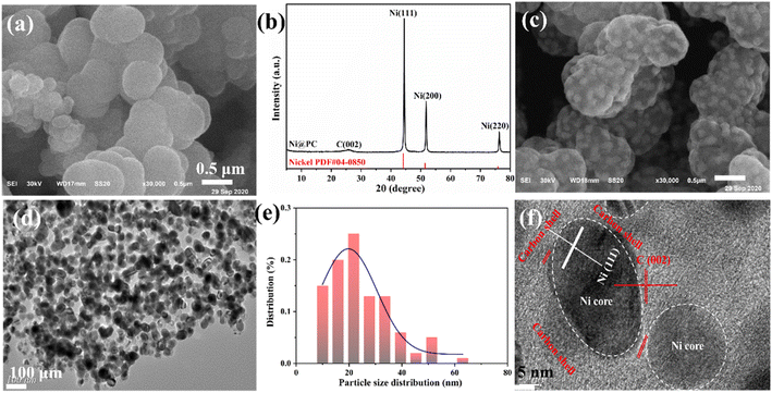 | ||
| Fig. 2 (a) SEM images of Ni-MOF. (b) XRD pattern of Ni@PC. SEM (c) and TEM (d, f) images of Ni@PC. (e) The particle size distribution of Ni. | ||
The pore structures of Ni@PC are evaluated via the N2 adsorption–desorption isotherm (Fig. 3a). Mixed isotherms of type I and type IV with hysteresis loops are exhibited, indicating the presence of mesoporous and microporous structures. Accordingly, the calculated pore size distribution indicates that the internal pores of Ni@PC composites consist of mesopore and macropore (Fig. 3b). These pores not only facilitate the penetration of the electrolyte but also are beneficial to the encapsulation of sulfur particles.18 Moreover, the Brunauer–Emmett–Teller (BET) surface area and total pore volume of Ni@PC are 129.4 m2 g−1 and 0.504 cm3 g−1, respectively. This high-porosity porous structure is favorable for the penetration of electrolytes, providing sufficient space for sulfur loading, the rapid and durable electrochemical reactions. In addition, the XRD pattern of S/Ni@PC cathodes prepared by the typical melting diffusion method demonstrates the typical diffraction peak of S (Fig. 3c), and the peak intensity of Ni decreases significantly (Fig. S2†), indicating that the sulfur powder has successfully diffused into the pores of Ni@PC.18 Meanwhile, the S content in S/Ni@PC composites determined by TGA is 69 wt% (Fig. 3d), which is close to the theoretical value.
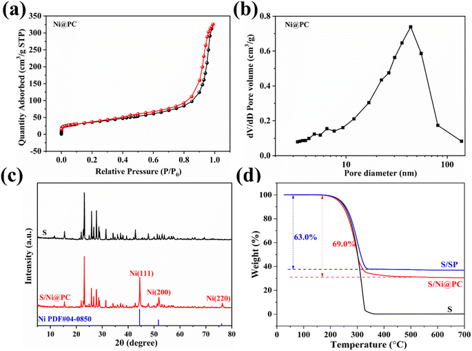 | ||
| Fig. 3 N2 adsorption and desorption isotherms (a), calculated pore-size distributions (b) and (c) XRD patterns of S@Ni@PC. (d) TGA curve of S/Ni@PC and S/SP in the N2 environment. | ||
The interaction between Ni@PC and LiPS is tested by static visible adsorption. After 24 h, the color of the vials labeled Ni@PC becomes colorless, while the Li2S6 solution remains primrose yellow after adding SP, indicating there is a strong interaction between Ni@PC and LiPSs. In order to further investigate the mechanism of chemisorption, XPS tests are performed before and after adsorption. As shown in the S 2p spectrum (Fig. 4a), except for bridge S (165.3 eV) and terminal S (164.0 eV) of Li2S6. The appearance of the Ni–S bond (162.3 eV) further verifies the interaction between LiPSs and metal Ni.24 Meanwhile, three peaks are also found at 167.6, 169.2 and 170.4 eV in the high binding energy region, indicating the formation of sulfate and thiosulfate complexes.24 For the Ni 2p spectrum (Fig. 4b), the Ni 2p spectrum can be deconvolved into four peaks assigned to Ni0 2p3/2 (853.1 eV), Ni2+ 2p3/2 (855.6 eV), Ni0 2p1/2 (871.1 eV) and Ni2+ 2p1/2 (873.6 eV) peaks.24 After adsorption, the peaks of Ni shift towards higher binding energy, indicating that the electrons are transferred from metal Ni to the S atoms of Li2S6, thus changing the electron cloud density. Furthermore, the content of Ni2+ in Ni@PC-Li2S6 is higher than that in Ni@PC. The change of chemical valence indicates that the Ni metal in Ni@PC may also participate in the redox reaction. By interacting with LiPSs, it can act as a medium/catalyst to improve reaction kinetics.24
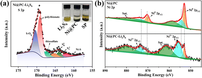 | ||
| Fig. 4 The images of LiPSs solutions samples adsorbed by Ni@PC and SP (a). S 2p (a) and Ni 2p (b) high-resolution XPS spectra of Li2S6 adsorbed by Ni@PC. | ||
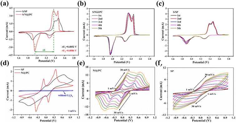
In order to demonstrate the advantages of S/Ni@PC, the cyclic voltammetry (CV) is performed on S/Ni@PC and S/SP cathodes in the voltage range of 1.6–2.8 V in Fig. 5a. At the scanning rate of 0.1 mV s−1, the CV curves of S/Ni@PC and S/SP show two reduction peaks, corresponding to the reduction of S8 to high-order Li2Sx (4 ≤ x ≤ 8) and the further reduction of these polysulfides to solid Li2S2/Li2S.25 The oxidation peaks are attributed to the oxidation of Li2S2/Li2S back to long-chain LiPS and S8.25 Compared with the S/SP cathode, a shift of the cathodic toward higher potential and the anodic peak toward lower potential in the CV curves of the S/Ni@PC cathode are exhibited. A decreased potential difference (i.e. lower polarization) between these two peaks indicates an improved redox reaction kinetics for the S/Ni@PC cathode.26 Moreover, the apparent positive shift and a negative shift in the onset reduction and oxidation peaks are exhibited in the CV curve of the S/Ni@PC cathode, accompanied by a higher peak current, confirming the excellent catalytic performance of uniformly dispersed Ni nanoparticles.26 In addition, excellent electrochemical reversibility with satisfactory overlap is also achieved (Fig. 5b and c).
The CV of the Li2S6 symmetrical cell is conducted to further reveal the electrocatalytic efficiency of Ni nanoparticles (Fig. 5d). There are two pairs of redox peaks in the CV curves of Ni@PC, corresponding to electrochemical steps of Li2S6 ↔ Li2S2/Li2S (at −0.36/−0.08 V) and Li2S8 ↔ Li2S6 (at 0.08/0.36 V).26,27 In contrast, no CV peak is observed without the Li2S6 electrolyte, confirming that the well-defined redox peaks originate from the LiPS conversion step.27 However, only a pair of redox peaks in the CV curves of SP appears at −0.63/0.65 V, indicating the limited and incomplete conversion rate of LiPSs without an effective catalyst27 (Fig. 5d). In addition, for Ni@PC materials, the peak current increases after the 10th cycle (Fig. S3†), and the redox peaks remain with only slight offsets even at the high scanning rates of 30 mV s−1 (Fig. 5e), suggesting that the polysulfide conversion process is progressing smoothly and efficiently.18,27 In contrast, the redox peak of SP is greatly shifted at a high scanning rate, indicating its poor catalytic capacity (Fig. 5f).
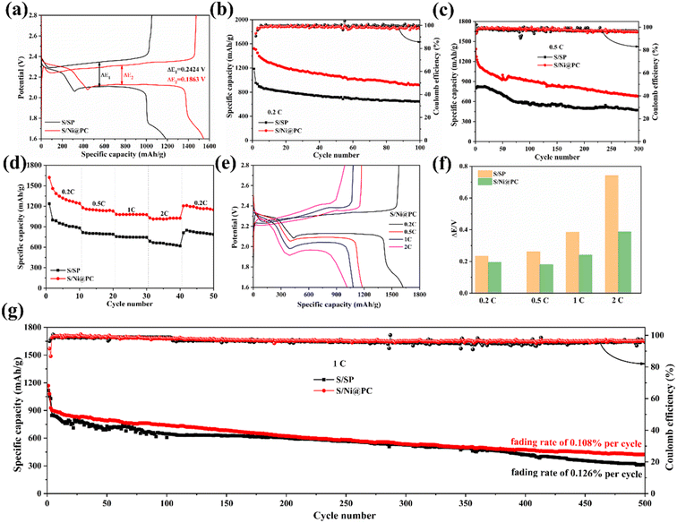
The enhanced catalytic activity and kinetics are also reflected in galvanostatic current discharge/charge curves, where the discharge plateau is consistent with the CV curves (Fig. 6a). The polarization (ΔE) is defined as the voltage difference between charge and discharge at a half discharge capacity.26 The S/Ni@PC cathode shows a lower polarization potential than the S/SP positive electrode and still maintains an extremely lower polarization potential even after 50 cycles (Fig. S4 and S5†). At such a low polarization potential, the S/Ni@PC cathode obtains the initial discharge capacity of 1544.6 mA h g−1 and a reversible capacity of 915.0 mA h g−1 even after 100 cycles (Fig. 6b), showing high capacity and excellent cyclic stability. In contrast, the S/SP cathode exhibits a humble capacity and poor capacity retention rate (54.3%) during the charge/discharge process due to its limited conversion rate of LiPSs. Furthermore, a high discharge capacity of 1387.4 mA h g−1 and a stable discharge capacity of 677.7 mA h g−1 over 300 cycles for S/Ni@PC cathode are exhibited at 0.5C (Fig. 6c and S6†), which is significantly higher than that of the S/SP cathode. These all prove that the reasonable design of Ni@PC catalyst is helpful to enhance sulfur utilization rate and obtain high capacity.
In addition to cyclic behavior, the rate performance is also critical to batteries. The rate performance of S/Ni@PC and S/SP cathodes at different current densities of 0.2–2C are tested. As shown in Fig. 6d, the discharge capacities of S/Ni@PC cathode are 1620.7, 1179.1, 1081.1, and 1029.4 mA h g−1 at 0.2, 0.5, 1, and 2C, respectively, which is obviously larger than that of S/SP cathode (1235.6, 814.5, 757.4 and 687.7 mA h g−1 at 0.2, 0.5, 1 and 2C). The enhanced rate performance of the S/Ni@PC cathode is attributed to the presence of Ni nanoparticles, resulting in the rapid redox kinetics of LiPSs.18 When the current density is returned to 0.2C, the discharge capacity of the S/Ni@PC cathode is restored to 1211.0 mA h g−1, indicating its excellent structural stability. The corresponding charge/discharge curves and polarization behavior of the two cathodes are shown in Fig. 6e and f and S7.† When the current density increases from 0.2C to 2C, S/Ni@PC maintains a small increase in ΔE. In contrast, the S/SP cathode exhibits greater polarization due to limited active sites.
In addition, the cyclic performance of the S/Ni@PC and S/SP positive electrode at a high rate of 1C is further measured (Fig. 6g). After being activated for two cycles at 0.2C, the initial discharge capacity of the S/Ni@PC cathode is 927.7 mA h g−1 and a capacity of 424.4 mA h g−1 remains, corresponding to a decay rate of 0.108% per cycle. These results clearly show that high sulfur utilization and capacity are achieved by introducing Ni nanoparticles into the porous carbon.
In conclusion, the high capacity and excellent rate capability of S/Ni@PC are attributed to (Fig. 7): (1) core (Ni)–shell (carbon) structure with gradient adsorption capacity makes the Ni nanoparticles expose more active sites, providing efficient electrocatalytic activity and effectively suppresses shuttle effect; (2) the porous structures, especially suitable mesopore and macropore, allow efficient charge transfer and rapid diffusion of ions. The synergistic effect effectively enhances the conversion rate of LiPSs and improves the utilization of sulfur.
4 Conclusions
In conclusion, the Ni@PC core–shell structure with adsorption gradient was successfully synthesized by a simple hydrothermal method and one-step pyrolysis. Ni nanoparticles not only inhibit the shuttle effect by trapping LiPSs but also reduce the electrochemical reaction polarization and catalyze the redox reaction. Simultaneously, appropriate pore volume can enhance the electrolyte wettability, adapt to volume expansion, and improve sulfur utilization and structural stability. As a result, the S/Ni@PC cathode exhibited an impressive capacity of 1544.6 mA h g−1 at 0.2C, and still had a capacity of 1014.6 mA h g−1 even at 2C, and a loss rate of 0.11% per cycle was obtained after 500 cycles at 1C.Conflicts of interest
There are no conflicts to declare.Acknowledgements
The authors gratefully acknowledge the financial support by the Basic Research Project Fund of Shanxi Province of China (no 20210302124491 and 20210302123341), Scientific and Technologial Innovation Programs of Higher Education Institutions in Shanxi (STIP, 2021L383).References
- M. Nojabaee, B. Sievert, M. Schwan, J. Schettler, F. Warth, N. Wagner, B. Milow and K. A. Friedrich, J. Mater. Chem. A, 2021, 9(10), 6508–6519 RSC.
- X. F. Yang, X. Li, K. Adair, H. M. Zhang and X. L. Sun, Electrochem. Energy Rev., 2018, 1(3), 239–293 CrossRef CAS.
- G. L. Cui, G. R. Li, D. Luo, Y. G. Zhang, Y. Zhao, D. R. Wang, J. Y. Wang, Z. Zhang, X. Wang and Z. W. Chen, Nano Energy, 2020, 72, 104685–104693 CrossRef CAS.
- Y. H. Ge, Z. Chen, S. J. Ye, Z. F. Zhu, Y. F. Tu and X. M. Yang, J. Mater. Chem. A, 2018, 6(30), 14885–14893 RSC.
- T. Wang, G. L. Cui, Y. Zhao, A. Nurpeissova and Z. Bakenov, J. Alloys Compd., 2021, 853, 157268 CrossRef CAS.
- T. T. Li, C. He and W. X. Zhang, J. Energy Chem., 2021, 52, 121–129 CrossRef CAS.
- J. M. Han, Q. Fu, B. J. Xi, X. Y. Ni, C. L. Yan, J. K. Feng and S. L. Xiong, J. Energy Chem., 2021, 52, 1–11 CrossRef CAS.
- Y. Z. Song, W. Zhao, L. Kong, L. Zhang, X. Y. Zhu, Y. L. Shao, F. Ding, Q. Zhang, J. Y. Sun and Z. F. Liu, Energy Environ. Sci., 2018, 11(9), 2620–2630 RSC.
- X. L. Ji, K. T. Lee and L. F. Nazar, Nat. Mater., 2009, 8(6), 500–506 CrossRef CAS PubMed.
- M. Zhao, Y. Q. Peng, B. Q. Li, X. Q. Zhang and J. Q. Huang, J. Energy Chem., 2021, 56, 203–208 CrossRef CAS.
- N. N. Wang, Y. Hong, T. X. T. Liu, Q. Wang and J. R. Huang, Ceram. Int., 2021, 47(1), 899–906 CrossRef CAS.
- W. L. Wei and P. Liu, Microporous Mesoporous Mater., 2021, 311, 110705 CrossRef CAS.
- J. Z. Wang, L. Lu, M. Choucair, J. A. Stride, X. Xu and H. K. Liu, J. Power Sources, 2011, 196(16), 7030–7034 CrossRef CAS.
- H. J. Peng, G. Zhang, X. Chen, Z. W. Zhang, W. T. Xu, J. Q. Huang and Q. Zhang, Angew. Chem., Int. Ed., 2016, 55(42), 12990–12995 CrossRef CAS PubMed.
- Q. Li, J. N. Guo, J. Zhao, C. C. Wang and F. Yan, Nanoscale, 2019, 11(2), 647–655 RSC.
- H. L. Ye, J. G. Sun, S. L. Zhang, H. B. Lin, T. R. Zhang, Q. F. Yao and J. Y. Lee, Stepwise electrocatalysis as a strategy against polysulfide shuttling in Li-S batteries, ACS Nano, 2019, 13(12), 14208–14216 CrossRef CAS PubMed.
- X. Zhou, R. j. Meng, N. Zhong, S. F. Yin, G. Q. Ma and X. Liang, Small Methods, 2021, 5(10), 2100571–2100580 CrossRef CAS PubMed.
- P. P. Liu, X. X. Liu, Q. Guo, X. T. Ma, J. M. Liu, X. X. Zhou and S. B. Liu, Solid State Ionics, 2022, 385, 116022 CrossRef CAS.
- J. Li, C. M. Jiao, J. H. Zhu, L. B. Zhong, T. Kang, S. Aslam, J. Y. Wang, S. F. Zhao and Y. J. Qiu, J. Energy Chem., 2021, 57, 469–476 CrossRef CAS.
- H. B. Wu, S. Y. Wei, L. Zhang, R. Xu, H. H. Hng and X. W. Lou, Chem.–Eur. J., 2013, 19(33), 10804–10808 CrossRef CAS PubMed.
- C. G. Wang, H. W. Song, C. C. Yu, Z. Ullah, Z. X. Guan, R. R. Chu, Y. F. Zhang, L. Y. Zhao, Q. Li and L. W. Liu, J. Mater. Chem. A, 2020, 8(6), 3421–3430 RSC.
- F. Zhou, Z. S. Qiao, Y. G. Zhang, W. J. Xu, H. F. Zheng, Q. S. Xie, Q. Luo, L. S. Wang, B. H. Qu and D. L. Peng, Electrochim. Acta, 2020, 349, 136378 CrossRef CAS.
- Z. Q. Li and L. W. Yin, ACS Appl. Mater. Interfaces, 2015, 7(7), 4029–4038 CrossRef CAS PubMed.
- W. J Wang, Y. Zhao, Y. G. Zhang, N. Liu and Z. Bakenov, J. Mater. Sci. Technol., 2021, 74, 69–77 CrossRef.
- D. H. Wang, G. X. Zheng, W. Y. Zhang, X. X. Niu, J. Z. Yan, T. S. Nie, Z. Ji, Y. S. Gu and X. Q. Yan, J. Alloys Compd., 2021, 881, 160496–160504 CrossRef CAS.
- H. Zhang, M. C. Zou, W. Q. Zhao, Y. S. Wang, Y. J. Chen, Y. Z. Wu, L. X. Dai and A. Y. Cao, ACS Nano, 2019, 13(4), 3982–3991 CrossRef CAS PubMed.
- Q. P. Wu, Z. G. Yao, X. J. Zhou, J. Xu, F. H. Cao and C. L Li, ACS Nano, 2020, 14(3), 3365–3377 CrossRef CAS PubMed.
Footnote |
| † Electronic supplementary information (ESI) available. See DOI: https://doi.org/10.1039/d3ra01339a |
| This journal is © The Royal Society of Chemistry 2023 |


