DOI:
10.1039/D3RA01260C
(Paper)
RSC Adv., 2023,
13, 11557-11568
Lumino-structural properties of Dy3+ activated Na3Ba2LaNb10O30 phosphors with enhanced internal quantum yield for w-LEDs
Received
24th February 2023
, Accepted 24th March 2023
First published on 13th April 2023
Abstract
With an intend to develop white light emitting phosphor, for w-LED application, a series of dysprosium (Dy3+) doped novel Na3Ba2LaNb10O30 phosphors were prepared using solid state reaction technique at 1300 °C. Their structural, morphological and vibrational spectroscopic analysis was performed. We illustrate the luminescence characteristics of the prepared phosphors for various Dy3+ ion doping concentration. The XRD analysis demonstrates that the prepared phosphors were in single phase, and of tetragonal tungsten bronze structure of the P4bm space group. The FE-SEM image reveals that the prepared phosphors contained irregular shaped both nano and micro particles. Under near-ultraviolet (n-UV) irradiation at 387 nm, the photoluminescence (PL) emission spectra shows three characteristic bands at 481 nm (blue), 575 nm (yellow) and 666 nm (red). Obtained optimized Dy3+ ion concentration for the prepared sample is 7.0 mol%, beyond which the concentration quenching begins. Bonding between Dy–O is covalent in nature as confirmed by bonding parameters and the Dexter theory revealed that the energy transfer among Dy3+ ions is dipole–diploe interaction. CIE chromaticity coordinates, CCT and color purity confirms the formation of warm white light emitting phosphors. Lifetime analysis demonstrates the longer decay time in the phosphors. The Internal Quantum Yield (IQE) and brightness (B) for the optimised phosphor is calculated as 45.35% and 11.41% respectively, which makes it a suitable phosphor for w-LED.
1 Introduction
Phosphor is any material that exhibits the phenomenon of luminescence when subjected to UV radiation, X-rays, electron bombardment, friction or any other form of excitation. A phosphor primarily comprises of a host matrix and an activator ion in its lattice.1 These activators act as the luminescent centres, i.e. the electron relaxes radiatively at this activator site, within the host matrix. Rare earth elements such as Eu3+, Eu2+, Dy3+, Pr3+ are few example of activators. Phosphors are used, in the creation of several optoelectronic devices, including light converters, solid state lasers, solid state lighting, optical thermometer and optical amplifiers, etc.2–7 In the last decade, phosphor-converted white light emitting diodes (pc-wleds) have been studied significantly owing to their key characteristic, such as efficient light output, low power consumption, longer operational lifetime (>100![[thin space (1/6-em)]](https://www.rsc.org/images/entities/char_2009.gif) 000 hours), sturdiness and environmentally safer as compared to their predecessors, fluorescent and incandescent lamp.8–12 Nowadays, w-LEDs are widely used in plant cultivation (including vegetables, flowers, herbs, etc.), display, medical lighting, and outdoor lighting.13–15
000 hours), sturdiness and environmentally safer as compared to their predecessors, fluorescent and incandescent lamp.8–12 Nowadays, w-LEDs are widely used in plant cultivation (including vegetables, flowers, herbs, etc.), display, medical lighting, and outdoor lighting.13–15
White light emission can be obtained in three ways from solid state lighting sources.16,17 The first way is to setup an array of multiple LED chips emitting light at different frequencies. Multiple LED setup has excellent colour rendering index and the white point can be easily controlled. However, there is no control on correlated colour temperature, since each LED needs an independent output power control and has its own different lifetime. The second way is to use a single UV LED chip coated with a combination of red, green and blue down-converting phosphors. This setup is quite cost efficient than LED matrix, as it gives excellent colour rendering and a control over white light-CCT. Because of stokes conversion, this approach becomes less energy efficient, and it is difficult to manage the homogeneity of the phosphor coating. Another demerit is that phosphors deteriorate faster than LEDs. The third way is utilizing a single LED (blue) with a coating of yellow down-converting phosphor. The blue light bleeds through the phosphor to give white light. This setup is small, light-weight, easy to operate and has a long lifetime. Demerit of this setup is that it is less efficient because of stokes shift and has a very poor colour rendering.
Since niobates have better chemical and physical stability, they make excellent luminous matrixes. Some rare-earth ion doped niobates, such as Sr2LaNbO6:Eu3+,Sm3+; LaNbO4:Bi3+/Dy3+ and Ca2LaNbO6:Sm3+, have been shown to exhibit outstanding luminous characteristics along with high thermal stability.18–20 It is important to note that the tungsten bronze structure (TTB) exhibits chemical and magnetic stability with excellent crystal structure. Niobates having TTB structures are excellent candidates for ferroelectric and piezoelectric materials. The deficient perovskite TTB niobates consist of corner-sharing NbO6 octahedra arrays and three different tunnels for cation filling, leading to large spontaneous polarization and high dielectric constants.21 In deformed metal–oxygen polyhedra, they likewise show dominating electron–hole separation and transport through static electric fields between structure-induced dipole moments. As a result, a little structural change such as changing the cation-site occupancy has a huge influence on charge mobility. Utilising this property, we have opted to use niobate based TTB structure to investigate its photoluminescence properties. Moreover, the tungsten bronze phosphors such as Sr5YTi3Nb7O30, NaSr2Nb5O15 and Ba4LaTiNb9O30 have been reported to have potential applications in photonics, especially in w-LED.22–24 The tetragonal tungsten bronze structure has been shown to readily accept lanthanides or transition metals as constituents or dopants because of its tetragonal crystal structure, which enables the manufacture of high-quality doped single crystals.25 The general practice to prepare niobate-based phosphors is the solid state reaction method, which has the benefit of producing samples with excellent morphology and luminosity, over other methods.26
In search of a suitable host lattice, scientists have been conducting research in order to prepare phosphor-converted white light emitting diode (pc-wled).27 In our present study, we focus towards the generation of white light from dysprosium doped Na3Ba2LaNb10O30 phosphors via solid state reaction technique. We examine the structure parameter, surface morphology and elemental analysis of the as prepared phosphors using the X-ray diffraction (XRD), field emission scanning electron microscopy (FESEM) and energy dispersive X-ray spectroscopy (EDX), respectively. Further, optical properties were examined employing the steady-state and time resolved photoluminescence.
Generally, Dy3+ ions exhibit three emission bands in the visible spectra, the blue emission (450–490 nm) corresponds to 4F9/2 → 6H15/2 transition, yellow emission (550–590 nm) corresponds to 4F9/2 → 6H13/2 hypersensitive transition and the red emission (640–680 nm) corresponds to 4F9/2 → 6H11/2 transition, latter being a feeble transition.28–30
2 Experimental procedure
2.1 Phosphor preparation
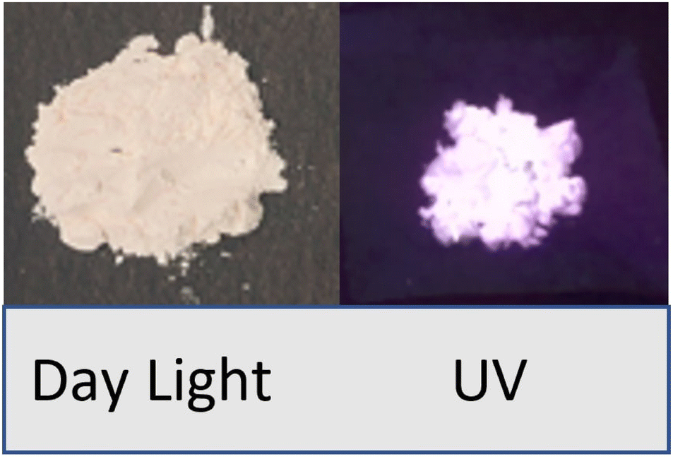
The samples of dysprosium doped niobate-based Na3Ba2LaNb10O30:xDy3+ (x = 0, 1, 3, 5, 7 and 10 mol%) phosphors have been synthesized via high-temperature solid-state reaction technique. The raw materials Na2CO3 (99.5%), BaCO3 (99.9%), La2O3 (99.9%), Dy2O3 (99.9%) and Nb2O5 (99.9%) used for the synthesis were of Sigma Aldrich and analytical grade quality. The precursor were taken in their stoichiometric ratios and were thoroughly mixed and milled together in a mortar and pestle for 2 hours. The grounded samples were subsequently calcinated at a heating rate of 3 °C min−1, in a programmable muffle furnace of Metrex Scientific Instruments (Model: MF-14P). The heating process consisted of two steps. The reaction time for the first step of calcination was 5 hours at 800 °C and the second step was 1300 °C for 7 hours. Finally the samples were rigorously grounded to make a fine powder and the phosphorescence for the optimised sample (7 mol%) can be easily seen in Fig. 1. The chemical reaction involved in this process is shown in eqn (1).| |
 | (1) |
 |
| | Fig. 1 Image of Na3Ba2LaNb10O30:xDy3+ (x = 7 mol%) phosphor sample under daylight and 365 nm UV light. | |
2.2 Characterization techniques
The structural parameter of the prepared phosphors were investigated by XRD analysis using Panalytical model X'pert Pro with Cu-Kα radiation (λ = 1.5406 Å) in the 2θ range from 20° to 80°. The surface morphology, energy dispersive spectroscopy (EDS), and elemental mapping of the prepared samples were investigated by FESEM. A thin layer of gold (Au) was coated on the as-synthesized samples and were analysed using FESEM utilising JEOL JSM-6490 operated at the accelerating voltage of 5 kV. The Fourier transform infrared (FT-IR) spectrum of Na3Ba2LaNb10O30 were recorded using a PerkinElmer Frontier Spectrometer in the middle infrared region (4000–400 cm−1) after the pellets were prepared by mixing the samples with potassium bromide (KBr2, A.R. grade) and then compressed using a hydraulic press at 10 ton load. The steady state photoluminescence spectra (PL) of the prepared phosphors were recorded using Cary Eclipse Fluorescence Spectrophotometer. The lifetime decay spectra has been studied using Horiba Spectroscope excited through a 150 watts microsecond xenon flash lamp. The excitation and emission spectra was collected in the range of 320–470 nm and 400–700 nm, respectively. The internal quantum efficiency (IQE) was collected by Horiba Scientific QuantaPhi-2 equiped with an integrating sphere coated with BaSO4. Commission international de l'Eclairage (CIE) 1931 chromaticity coordinates were calculated and plotted for the emission spectra. All measurements were carried out at room temperature.
3 Results and discussion
3.1 X-ray diffraction and structural analysis
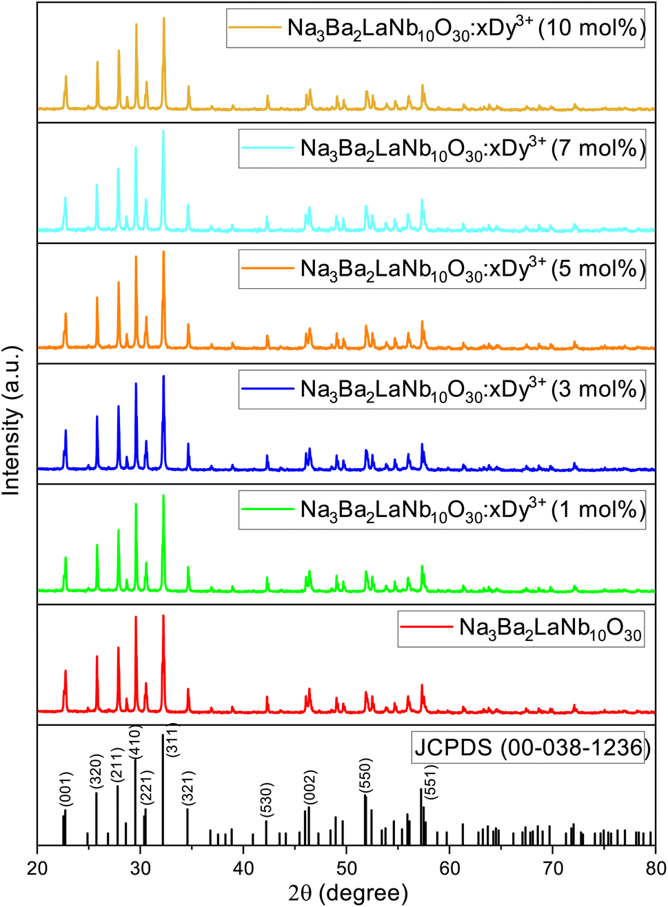
The powder X-ray diffraction (XRD) analysis demonstrated the crystal structure of Na3Ba2LaNb10O30:xDy3+ (x = 0, 1, 3, 5, 7 and 10 mol%) phosphors and matches well with the JCPDS card no. 00-038-1236 corresponding to Na3Ba2LaNb10O30, as shown in Fig. 2. XRD peaks reveals that the inclusion of dysprosium ion does not effect the crystal structure of Na3Ba2LaNb10O30. Furthermore, the crystal structure of Na3Ba2LaNb10O30:xDy3+ (x = 0, 1, 3, 5, 7 and 10 mol%) phosphor belongs to the filled tetragonal tungsten bronze (TTB) structure of the P4bm space group. The general representation of tungsten bronze structure is [(A1)2(A2)4]C4[(B1)2(B2)8]O30. It can be seen that the TTB structure consists of three different crystal sites namely six A sites, ten B sites (B crystal sites are located in the center of the [BO6] octahedrons), and the triangular interstitial C site (mostly empty).31 In the present study of Na3Ba2LaNb10O30:xDy3+ (x = 0, 1, 3, 5, 7 and 10 mol%), Ba2+ and La3+ present at two A1 crystal sites while Na1+ and Ba2+ are present at four A2 crystal sites whereas Nb5+ occupies all ten B sites. In order to figure out which element of the matrix is swapped with Dy3+ ion, the ionic radii percentage difference (Dr) is calculated and reproduced using the following expression.32| |
 | (2) |
where, Rs and Rd are the ionic radii of the cation in the matrix and doped Dy3+ ion respectively. The ionic radii of cations that corresponds to the coordination number six are Na1+(Rs = 1.02 Å), Ba2+(Rs = 1.35 Å), La3+(Rs = 1.032 Å), Nb5+(Rs = 0.64 Å) and doped ion Dy3+(Rd = 0.912 Å). The calculated Dr values are 10.59%, 32.44%, 11.63% and −42.5% respectively. Among all the cations, Na1+ and La3+ are the closest ions to be replaced by the Dy3+ ion. Since both La and Dy exist in trivalent oxidation state, Dy3+ ions would occupy the site of La3+ ion. Dy3+ will not substitute Na1+ as it leads to chemically nonequivalent substitution and the host lattice acquires an excess positive charge.
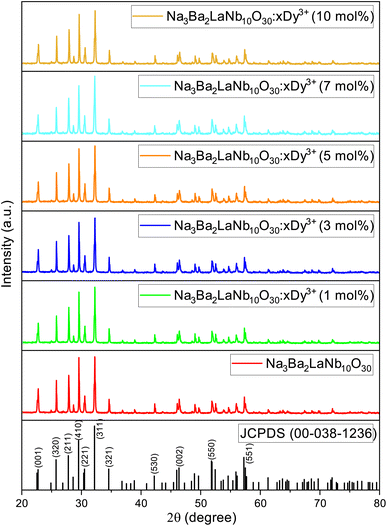 |
| | Fig. 2 XRD patterns of JCPDS 00-038-1236 and Na3Ba2LaNb10O30:xDy3+ (x = 0, 1, 3, 5, 7 and 10 mol%) phosphors. | |
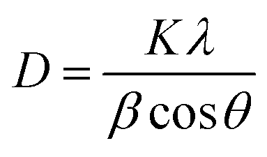
The Debye–Scherrer formula (eqn (3)) is employed to compute the average crystallite size of the prepared phosphors.33,34
| |
 | (3) |
where
K is the form factor (usually 0.94),
λ denotes the X-ray wavelength (1.5406 Å, for Cu-K
α),
θ represents the Braggs diffraction angle and
β denotes the FWHM (full-width at half maxima). For Na
3Ba
2LaNb
10O
30:
xDy
3+ (
x = 0, 1 and 10 mol%) phosphor, the average crystallite size is summarized in
Table 1. The results show that as the Dy
3+ ion concentration increased the
D value declines.
Table 1 Crystallite size of Na3Ba2LaNb10O30:xDy3+ (x = 1, 3, 5, 7 and 10 mol%) phosphors
| Dy3+ (mol%) |
Average crystallite size, D (nm) |
| 0.0 |
41.45057 |
| 1.0 |
40.35571 |
| 10.0 |
40.25051 |
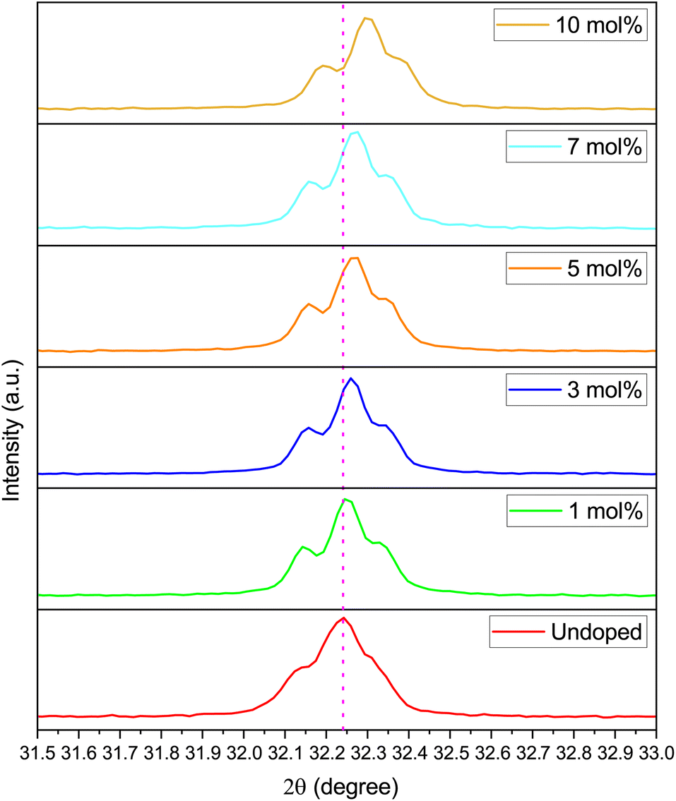
A very slight shift (of the order of 10−2 Å) in the 2θ angle of the most intense peak of Na3Ba2LaNb10O30 ((311) plane) is observed to shift towards the higher 2θ angle as we increase the doping concentration. This propensity may be brought on by the mismatch between the ionic radii of Dy3+ and La3+ ions, which further raises the possibility of Dy3+ ion incorporation into Na3Ba2LaNb10O30. This slight shift can be easily seen from Fig. 3.
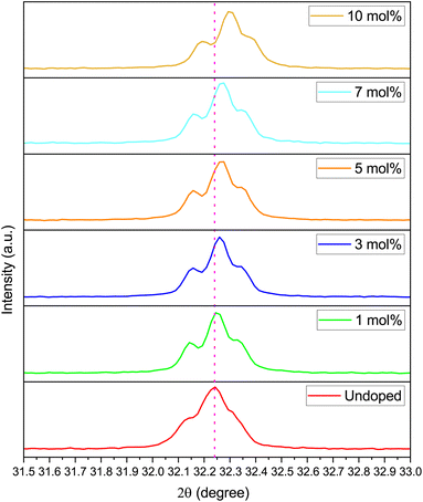 |
| | Fig. 3 XRD peak corresponding to 311 plane of Na3Ba2LaNb10O30:xDy3+ (x = 0, 1, 3, 5, 7 and 10 mol%) phosphors. | |
3.2 Field emission scanning electron microscopy and energy dispersive X-ray spectroscopy
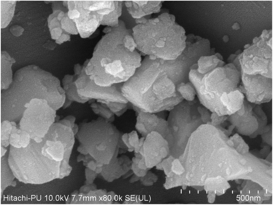
Surface morphology of the prepared Na3Ba2LaNb10O30:xDy3+ (x = 7 mol%) phosphor is obtained using FE-SEM depicted in Fig. 4. From FE-SEM images, the phosphor particles were inferred as non-uniform, inhomogeneous and irregular in shape. The agglomeration of particles were expected in the preparation of phosphor through high-temperature solid state reaction method. The agglomerated particle size range from few micrometers to few nanometers, and are tightly packed with each other. Because of the large surface area to volume ratio, number of voids are observed inside the agglomerated nanoparticles. No change in the morphology is observed with the change in dopant ion concentrations.
 |
| | Fig. 4 FE-SEM micrograph of Na3Ba2LaNb10O30:xDy3+ (x = 7 mol%) phosphor sintered at 1300 °C. | |
The EDX spectrum and elemental mapping reveals the chemical composition and elemental distribution in the prepared Na3Ba2LaNb10O30:xDy3+ (x = 7 mol%) phosphor. EDX is a typical approach for detecting and measuring the qualitative and quantitative elemental composition of a sample in an area of few square nanometer dimensions. The elemental peaks corresponding to sodium (Na), barium (Ba), lanthanum (La), niobium (Nb), oxygen (O) and dysprosium (Dy) of the prepared sample was observed in the EDX spectrum and are shown in Fig. 5. Their elemental mapping is demonstrated in Fig. 6 which depicts the even distribution of constituent elements. The atomic% shown in Fig. 5 also confirms the agglomeration of Na3Ba2LaNb10O30:xDy3+ (x = 7 mol%) doped phosphor.
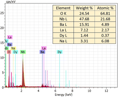 |
| | Fig. 5 EDX spectrum of Na3Ba2LaNb10O30:xDy3+ (x = 7 mol%) phosphor. | |
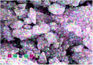 |
| | Fig. 6 Elemental mapping of Na3Ba2LaNb10O30:xDy3+ (x = 7 mol%) phosphor. | |
3.3 Raman and Fourier transform infrared spectroscopy
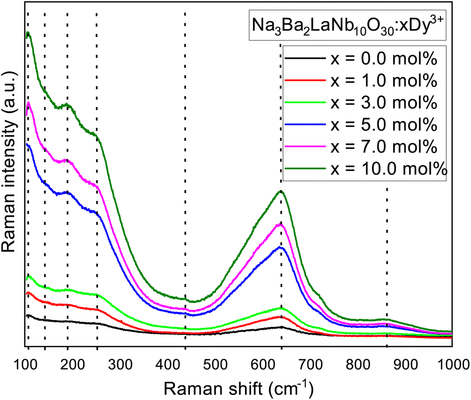
Raman spectra of the synthesized Na3Ba2LaNb10O30:xDy3+ (x = 7 mol%) phosphor in the tetragonal structure, with the octahedral ion [NbO6]7−, recorded at room temperature from 100–1000 cm−1 wavenumber as shown in Fig. 7. The three Raman active modes centered at 252 cm−1 (ν5) corresponds to O–Nb–O bend vibrations, 639 cm−1 (ν2) assign to Nb–O stretch vibrations, and 862 cm−1 (ν1) corresponds to Nb–O stretch vibrations, is similar to one other in tetragonal tungsten bronze structure with the point group C4ν (ref. 35 and 36) and C2ν.37 For the tungsten bronzes structure, all Raman lines except for the three characteristic vibrational modes originate from the external vibrations for oxygen octahedron. Therefore, the Raman spectra of Na3Ba2LaNb10O30 can be discussed in terms of internal vibrations of the (NbO6) octahedra and external vibrations involving the motions of Na1+, Ba2+ and La3+ cations. As shown in Fig. 7, the peaks centered at 108 cm−1, 142 cm−1, 189 cm−1 and 438 cm−1 originate from external vibration modes.
 |
| | Fig. 7 Raman spectrum of Na3Ba2LaNb10O30:xDy3+ (x = 0, 1, 3, 5, 7 and 10 mol%) phosphor at room temperature. | |
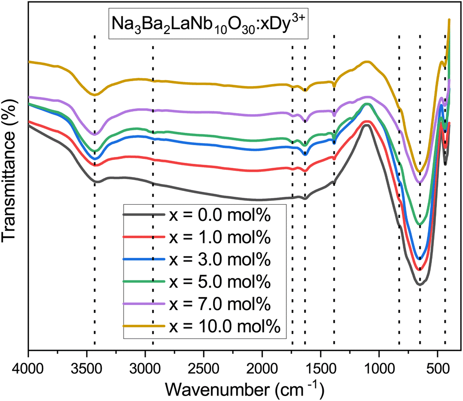
The FT-IR spectra are recorded from 4000–400 cm−1 wavenumber to know about the structural units and functional groups in the as-prepared Na3Ba2LaNb10O30:xDy3+ (x = 1, 3, 5, 7 and 10 mol%) phosphor. Fig. 8 depicted the FT-IR spectra of as-synthesized phosphor. The quality of product is best checked by the FT-IR spectroscopy and is used in the initial stage process for the analysis of material. The shift in the peaks of spectra suggests the inclusion of contaminate. All the spectra shows similar shoulder positions as demonstrated in the Fig. 8. FT-IR spectra contain eight shoulders about 435, 654, 829, 1386, 1633, 1743, 2921 and 3432 cm−1. The shoulders in the spectra are assigned according to the previously published research papers. The shoulder near 435 and 829 cm−1 consigned to the coupling between Nb–O stretching mode.38 The shoulder about 654 cm−1 is owing to the La–O stretching vibrations.39 The shoulder about 1386 cm−1 is because of symmetric stretching of COO− functional group.40 The shoulder in the region 1633 and 3432 cm−1 is because of water molecules.41 The shoulder near 1743 cm−1 is contributed by C–O stretching mode in free carboxylic group.42 The shoulder about 2921 cm−1 may correspond to the residual organic presence.43
 |
| | Fig. 8 Fourier transformed infrared (FT-IR) spectrum of Na3Ba2LaNb10O30:xDy3+ (x = 0, 1, 3, 5, 7 and 10 mol%) phosphor at room temperature. | |
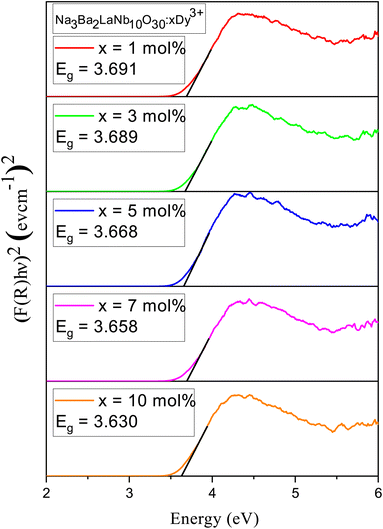
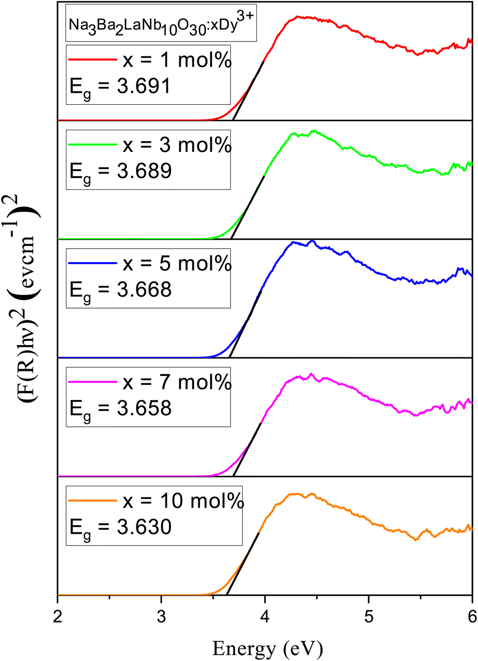
3.4 Bandgap and electronic structure
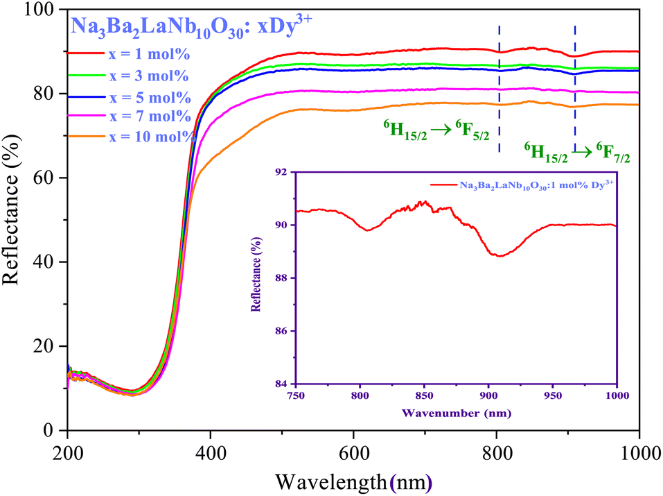
Using reflectance spectra we can explore optical characteristics of phosphors. Bandgap (Eg) of Na3Ba2LaNb10O30:xDy3+ (x = 1, 3, 5, 7 and 10 mol%) phosphor samples can be calculated using Tauc plot44 derived from the plot of diffuse reflectance spectra of the phosphors. Fig. 9 exhibit UV-Vis diffuse reflectance spectra of Na3Ba2LaNb10O30:xDy3+ (x = 1, 3, 5, 7 and 10 mol%) phosphor and Fig. 10 shows the corresponding Tauc plot determined from eqn (4). The transition 6H15/2 → 6F5/2 and 6H15/2 → 6F7/2 at 808 nm and 908 nm, respectively can be easily seen in Fig. 9.| | |
(αabshνph)n = A(hνph − Eg)
| (4) |
where A represents a constant, αabs denotes the absorption coefficient, νph represents the photon frequency and n is the transition dependent parameter (n = 1/2 corresponds to allowed electronic transition (direct), n = 2 for allowed electronic transition (indirect), while n = 3/2 and 3 corresponds to forbidden direct and indirect electronic transition, respectively). A red shift is represented in the optical bandgap of the Na3Ba2LaNb10O30:xDy3+ (x = 1, 3, 5, 7 and 10 mol%) phosphor with increase in Dy3+ ion concentration, as seen in Fig. 10. Table 2 shows the bandgap for Na3Ba2LaNb10O30:xDy3+ (x = 1, 3, 5, 7 and 10 mol%) phosphor.
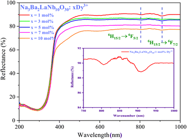 |
| | Fig. 9 Diffuse reflectance spectra of Na3Ba2LaNb10O30:xDy3+ (x = 1, 3, 5, 7 and 10 mol%) phosphor. | |
 |
| | Fig. 10 Tau plot of un-doped and Na3Ba2LaNb10O30:xDy3+ (x = 1, 3, 5, 7 and 10 mol%) phosphors for the determination of optical bandgap Eg (assuming indirect transitions). | |
Table 2 Bandgap, nephelauxetic ratio (β) and bonding parameter (δ) in Na3Ba2LaNb10O30:xDy3+ (x = 1, 3, 5, 7 and 10 mol%) phosphors
| Dy3+ (mol%) |
Bandgap (eV) |
Nephelauxetic |
Bonding |
| Ratio (β) |
Parameter (δ) |
| 1.0 |
3.691 |
0.99980 |
0.00021 |
| 3.0 |
3.689 |
0.99973 |
0.00028 |
| 5.0 |
3.668 |
0.99938 |
0.00062 |
| 7.0 |
3.658 |
0.99883 |
0.00117 |
| 10.0 |
3.630 |
0.99601 |
0.00401 |
3.5 Steady state photoluminescence
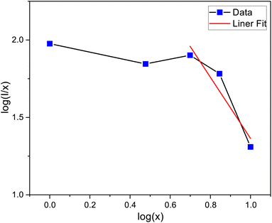
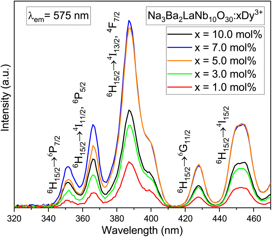
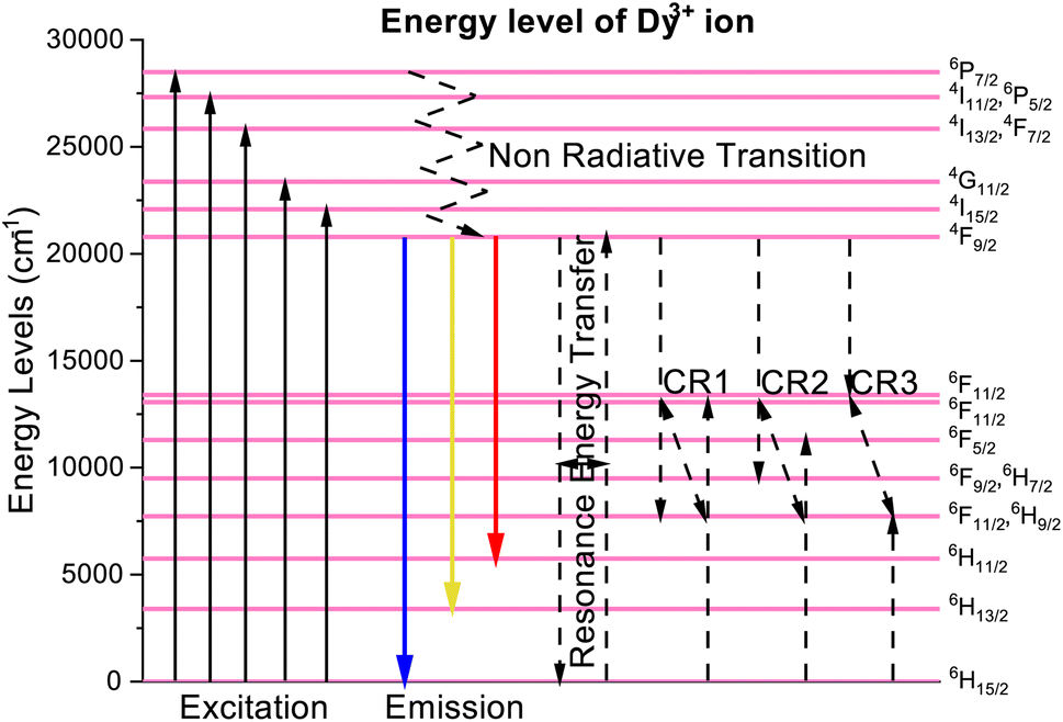
The photoluminescence excitation (PLE) spectra of dysprosium doped niobate-based Na3Ba2LaNb10O30:xDy3+ (x = 1, 3, 5, 7 and 10 mol%) phosphors are demonstrated in Fig. 11, which were performed in wavelength range 320–470 nm for fixed emission wavelength of 575 nm. Several excitation peaks were observed at 351, 366, 387, 427 and 453 nm due to the characteristic Dy3+ ion transitions from 6H15/2 (ground state) to several excited states as exhibited in Fig. 15. The five intense peaks correspond to 6H15/2 → 6P7/2(351 nm); 6H15/2 → 4I11/2, 6P5/2(366 nm); 6H15/2 → 4I13/2, 4F7/2(387 nm); 6H15/2 → 4G11/2(427 nm) and 6H15/2 → 4I15/2(453 nm) transitions.45,46 Hence, one can conclude that the synthesised phosphor shows potential for applications in near-Ultraviolet chips.
 |
| | Fig. 11 PLE spectra of Na3Ba2LaNb10O30:xDy3+ (x = 1, 3, 5, 7 and 10 mol%) phosphors by fixing emission at 575 nm. | |
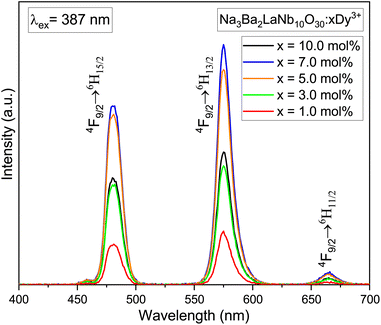
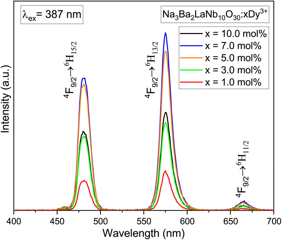
The photoluminescence (PL) emission spectra of Na3Ba2LaNb10O30:xDy3+ (x = 1, 3, 5, 7 and 10 mol%) phosphors taken in the range of 400–700 nm while keeping excitation wavelength fixed at 387 nm are presented in Fig. 12. The emission spectra shows three characteristic bands centred at 481, 575 and 666 nm which correspond to blue (4F9/2 → 6H15/2 transition), yellow (4F9/2 → 6H13/2 transition) and red (4F9/2 → 6H11/2 transition) respectively. Further, due to magnetic dipole nature of the 4F9/2 → 6H15/2 transition the surrounding crystal field lays no effect on it. Whereas, the forced electric dipole 4F9/2 → 6H13/2 transition of Dy3+ ion is sensitive to surrounding environment. Moreover the intensity of the yellow band is greater than the blue band signifying that the Dy3+ ions are present at the sites lacking inversion center in the host lattice.47,48 The optimized Dy3+ ion concentration is 7.0 mol%, beyond which the concentration quenching begins.
 |
| | Fig. 12 PL emission spectra of Na3Ba2LaNb10O30:xDy3+ (x = 1, 3, 5, 7 and 10 mol%) phosphors under the excitation wavelength of 387 nm. | |
3.6 Nephelauxetic ratio (β) and bonding parameter (δ)
To understand the behaviour of ligand field that surrounds the Dy3+ ions in the host matrix and to determine the nature of bonding, the (β) and (δ) are evaluated using the following expression:49| |
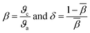 | (5) |
where, ϑc and ϑa are the wavenumbers in cm−1 for a specific transition of RE ion and the same transition of an aqua ion respectively and β represents the average value of all β. Nephelauxetic effect occurs because of the partially filled f-shell. When host matrix is incorporated with RE ions, the 4f shell gets deformed due to the influence of ligand field. The calculated values of β for Na3Ba2LaNb10O30:xDy3+ (x = 1, 3, 5, 7 and 10 mol%) are shown in Table 2.
The δ value strongly relate to the ligand field environment around the Dy3+ ions. The value may be positive/negative indicating ionic/covalent nature. The calculated values of δ for Na3Ba2LaNb10O30:xDy3+ (x = 1, 3, 5, 7 and 10 mol%) are shown in Table 2. The positive value indicates that the bond present between Dy–O is covalent in nature,50 which increases with the increase in Dy3+ ions concentration.
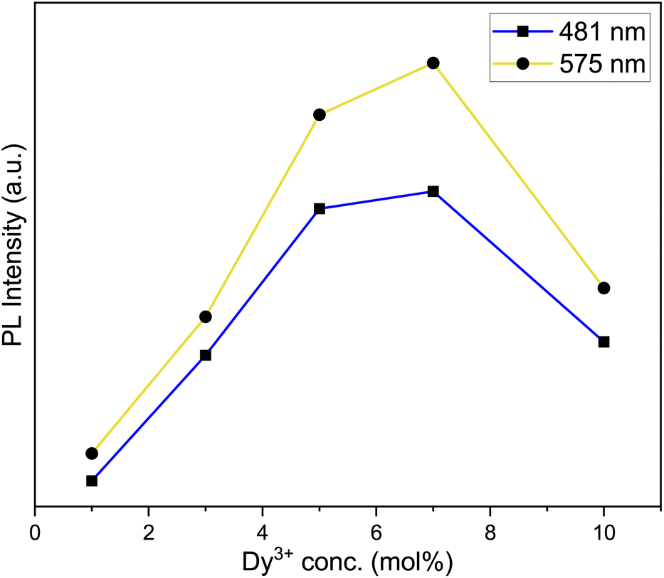
3.7 Effect of dysprosium doping concentration
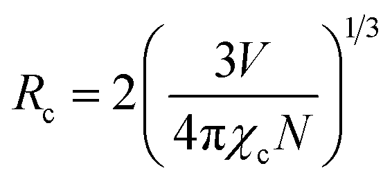
The emission spectra of Na3Ba2LaNb10O30:xDy3+ (x = 1, 3, 5, 7 and 10 mol%) in Fig. 12 showed the same peak positions for all the Dy3+ ions concentration. Fig. 13 shows the yellow and blue peak emission intensity of Na3Ba2LaNb10O30:Dy3+ phosphor with change in Dy3+ ion concentration. Fig. 13 reveals that the emission intensity depends upon the concentration of Dy3+ ion, and is seen to increase with steady increase in the latter upto 7 mol%. Beyond 7 mol% of Dy3+ ion concentration, the luminescence intensity in Na3Ba2LaNb10O30 phosphor begins to decrease due to quenching of the concentration. This supported the fact that as Dy3+ ion concentration increases beyond a certain value, here 7 mol%, the non-radiative energy transfer probability between dysprosium ions tends to increase. Theoretically, the critical distance (Rc) between Dy3+ ions after which concentration quenching begins can be calculated using the Blasse formula:51| |
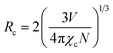 | (6) |
where V denotes the unit cell volume, N denotes the number of cation sites in the host unit cell and χc represents the fraction of activator concentration at which quenching occurs. For Na3Ba2LaNb10O30:Dy3+ phosphor, χc = 0.07, N = 1, V = 604.4425 Å, hence Rc can be calculated as 25.45 Å. Resonant energy transfer is primarily caused by exchange and multipolar interactions. The distance between the adjacent Dy3+ ions falls below the critical distance beyond the 7 mol% concentration of Dy3+ ions. Given that the calculated Rc value is greater than 5 Å, the multipolar interactions will be dominant in the concentration quenching of Na3Ba2LaNb10O30:Dy3+ phosphor as the probability of energy transfer via exchange interaction mechanism is very low.52
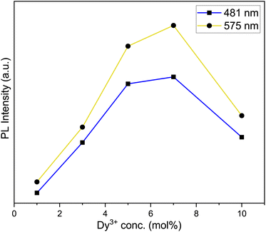 |
| | Fig. 13 Variation of emission intensity of the emission peaks to various Dy3+ ions concentration. | |
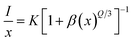
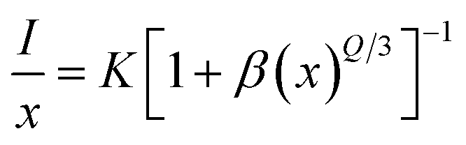
In line with Dexter's hypothesis,53 type of multipolar interaction mechanism between Dy3+–Dy3+ ions can be obtained using the eqn (7).
| |
 | (7) |
here
β and
K denote constants specific to the host lattice,
x represents the activator ion concentration, and
I denotes the photoluminescence emission intensity. The
Q value defines the multipolarity of electric interaction between the adjacent activator ion.
54 The multipolar character function
Q can take values of 3,6,8 and 10 according to the interaction mechanism being nearest neighbour, dipole–dipole (d–d), dipole–quadrupole (d–q) and quadrupole–quadrupole (q–q) respectively.
55 The
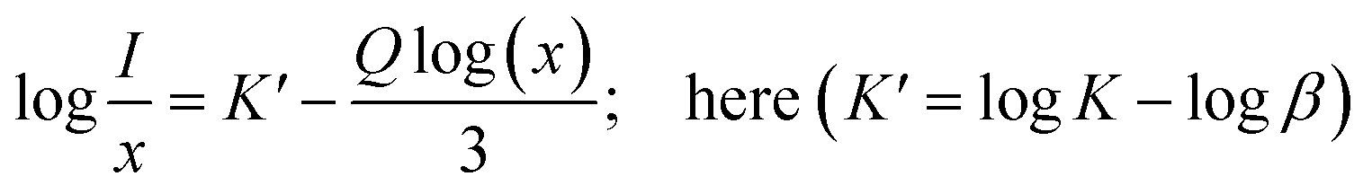
eqn (7) can be approximated to:
| |
 | (8) |
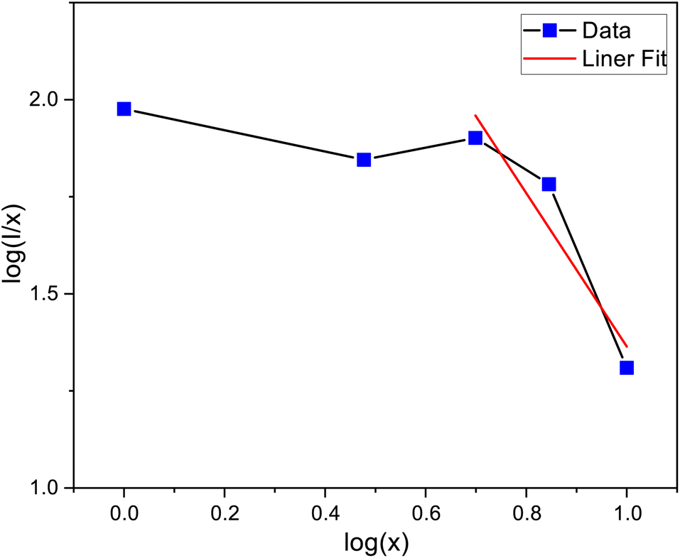
The linear dependance of log(I/x) and log(x) was analysed using 4F9/2 transition of dysprosium ion and is shown in Fig. 14. The calculated slope value prior to linear fit is −1.70753, which gives the Q value equivalent to 5.13 (close to 6). Thus, it can be stated that the main mechanism through which energy transfer occurs between the adjacent dysprosium ions is dipole–dipole interaction.
 |
| | Fig. 14 The linear fitting plot between log(I/x) and log(x). | |
The partial energy states of Na3Ba2LaNb10O30:Dy3+ phosphor is drawn in Fig. 15. The synthesized phosphor absorbs near ultraviolet light corresponding to it's absorption band originating from 6H15/2 (ground state) to different excited states. The phosphor Na3Ba2LaNb10O30:Dy3+ gets excited at 387 nm to populate the short-lived 4I13/2 and 4F7/2 excited state. The excited ions undergo multiphonon non-radiative transitions to relax to the low lying metastable 4F9/2 state. Since beyond this level, the energy spacing between various energy levels is negligible, hence the energy transfer mainly occurs through the non-radiative transitions. The rate of phonon emission (w) can be determined using eqn (9):
where
K is the Boltzmann constant,
E is the energy gap and
hνmax is the maximum energy of phonons.
 |
| | Fig. 15 Partial energy level diagram of Dy3+ in Na3Ba2LaNb10O30 phosphor. | |
Because of significant energy difference between 4F9/2 level and 6H15/2, 6H13/2, 6H11/2 levels, radiative photonic emission takes place. Cross relaxation (CR) channels and resonance energy transfer (RET) between nearby dysprosium ions may be responsible for the non-radiative energy transfer and concentration quenching. According to the energy match rule, the three cross-relaxation channels (CR1, CR2, and CR3) and potential resonant energy transfer are as follows:50,56,57
CR1: (4F9/2 + 6H15/2 → 6F11/2, 6H9/2 + 6F3/2) CR2: (4F9/2 + 6H15/2 → 6F9/2, 6H7/2 + 6F5/2) CR3: (4F9/2 + 6H15/2 → 6F1/2 + 6F11/2, 6H9/2) RET: (4F9/2 + 6H15/2 → 6H15/2 + 4F9/2).
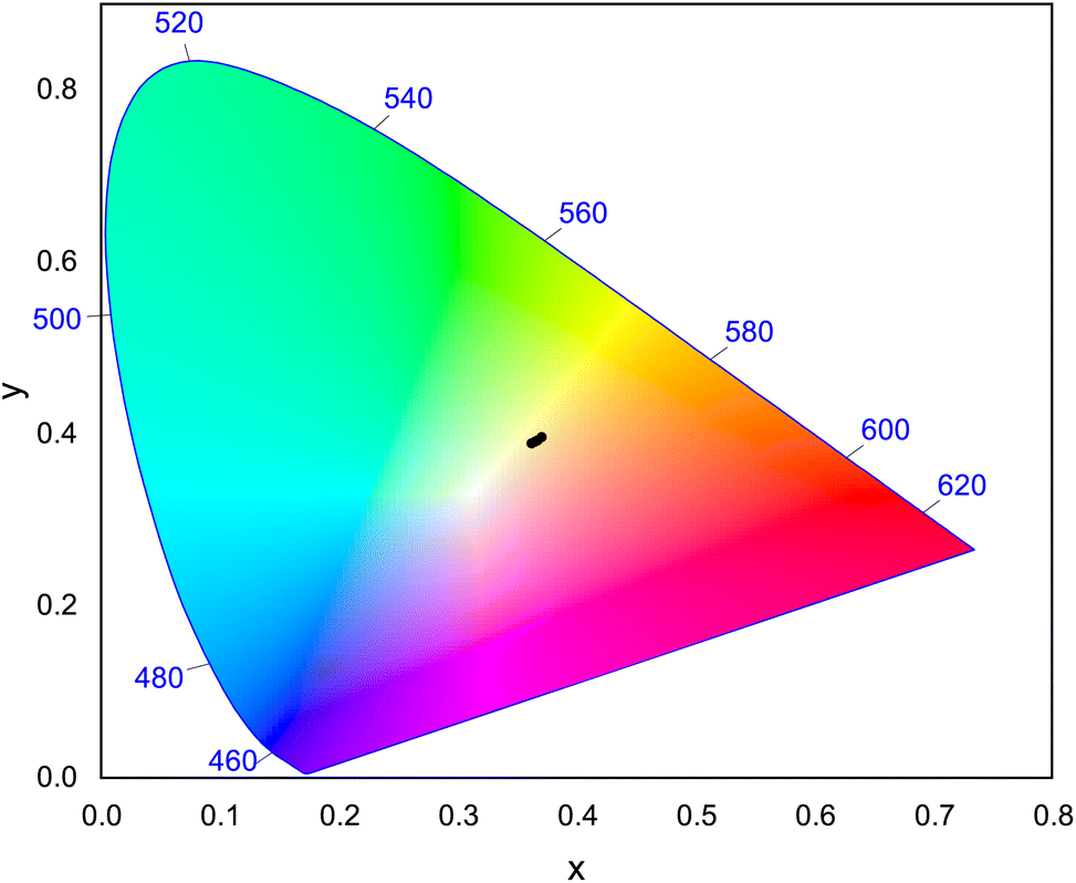
3.8 CIE chromaticity coordinate
CIE chromaticity58 coordinates were calculated and plotted on CIE 1931 chromaticity diagram, as shown in Fig. 16, using the emission spectra of Na3Ba2LaNb10O30:Dy3+ phosphors. Here, x and y correspond to the chromaticity coordinates in the CIE 1931 and were obtained as follows:| |
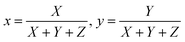 | (10) |
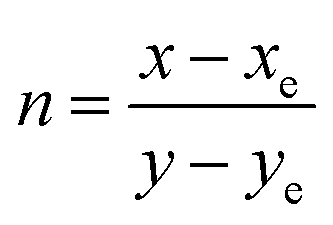
where X, Y, Z are the tristimulus values for the three primary colors i.e. red, green and blue, respectively. The calculated CIE coordinates are found to be quite close to the center white light point (0.33333, 0.33333), as observed in Fig. 16. Correlated color temperature (CCT)59 relate its color to the color of the light emitted by the black body at a particular temperature, and is measured in Kelvins. Based on the CCT, the phosphors fall in the warm white light region. McCamy's empirical formula60 was employed to calculate the CCT as stated in the eqn (11):| | |
CCT = −449n3 + 3525n2 − 6823.3n + 5520.33
| (11) |
where (xe = 0.332, ye = 0.186) is the epicenter and  is the inverse slope line.
 |
| | Fig. 16 CIE 1931 chromaticity diagram showing the color coordinates of Na3Ba2LaNb10O30:xDy3+ (x = 1, 3, 5, 7 and 10 mol%) phosphors. | |
Furthermore, the asymmetry ratio i.e. Y/B ratio is the relative measure of band intensities at 575 nm and 481 nm that is used to assess the effectiveness of Dy3+ ion doped phosphors. The asymmetry ratio is found close to 1, indicating the appropriate white emission for as prepared Dy3+ ion doped phosphor.61 The Y/B ratio for this investigation lies in the range of 1.18329 to 1.34318 as shown in Table 3. With the increase in Dy3+ ion concentration, the position of peak remains unaffected. The color purity of the prepared Na3Ba2LaNb10O30:xDy3+ (x = 1, 3, 5, 7 and 10 mol%) phosphor are calculated using the following formula:
| |
 | (12) |
where (
x,
y) denotes the CIE coordinates of the prepared phosphors, (
xd,
yd) denotes the dominant wavelength coordinates corresponding to the dominant wavelength (
λd), and (
xi,
yi) denotes the CIE coordinates of the reference white light. The color purity for the prepared samples are calculated between 19% and 24%. The low color purity value is the evident aspect indicating the purity for white light emission which is significantly lower than the previously indicated Dy
3+ doped phosphors.
62,63 CIE coordinates, CCT, Y/B ratio and color purity are shown in
Table 3.
Table 3 CIE coordinate, correlated color temperature, Y/B ratio and average decay time for Na3Ba2LaNb10O30:xDy3+ (x = 1, 3, 5, 7 and 10 mol%) phosphors
| Dy3+ (mol%) |
CIE coordinate |
CCT (K) |
Y/B ratio |
Color purity |
Average decay time (μs) |
| x |
y |
| 1.0 |
0.36724 |
0.39237 |
4455.777 |
1.322 |
23.001 |
302.559 ± 0.859 |
| 3.0 |
0.36210 |
0.38917 |
4585.400 |
1.183 |
19.645 |
249.539 ± 0.906 |
| 5.0 |
0.36695 |
0.39261 |
4464.850 |
1.263 |
22.842 |
242.453 ± 1.164 |
| 7.0 |
0.37063 |
0.39636 |
4383.463 |
1.343 |
25.364 |
238.778 ± 2.054 |
| 10.0 |
0.36496 |
0.39091 |
4512.177 |
1.240 |
21.508 |
207.428 ± 3.567 |
3.9 Lifetime analysis
The phenomenon responsible for the longer decay time is illustrated systematically in the Fig. 17. The Dy3+ ion happens to be a potent trap creating ion, and formation of these traps is a major cause for longer decay time. Moreover, the phosphor's luminescence intensity is influenced by the densities of the trapped electrons, whereas its duration is influenced by the depth of the trapped electrons. Phosphor materials when exposed to radiation, cause excitation of the charge carriers and they shift to a higher energy conduction band through process 1 illustrated in Fig. 17. There are two possible choices for these charge carriers to occupy the luminescence centres made by Dy3+ ions. One way is for the charge carriers to directly approach the luminescence centres via host conduction band (as directed by process 2). However, a fraction of the excited charge carriers get confined into electron traps (as directed by process 3), eventually storing some part of excitation energy. These trapped electrons do not come to the ground state directly, instead they are released from these traps, due to thermal excitations at proper temperature, and get transferred to the luminescent centres via host lattice. At these luminescent centres, Dy3+ characteristic emissions are observed (as directed by process 4). In physical systems, number of electron and hole traps may not be exactly equal and this embodies the cause for the characteristic luminescence.64
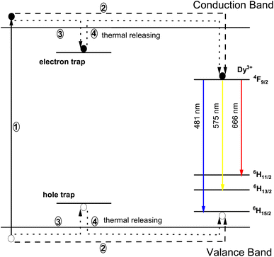 |
| | Fig. 17 Schematic diagram of the mechanism in Na3Ba2LaNb10O30:Dy3+ phosphor. | |
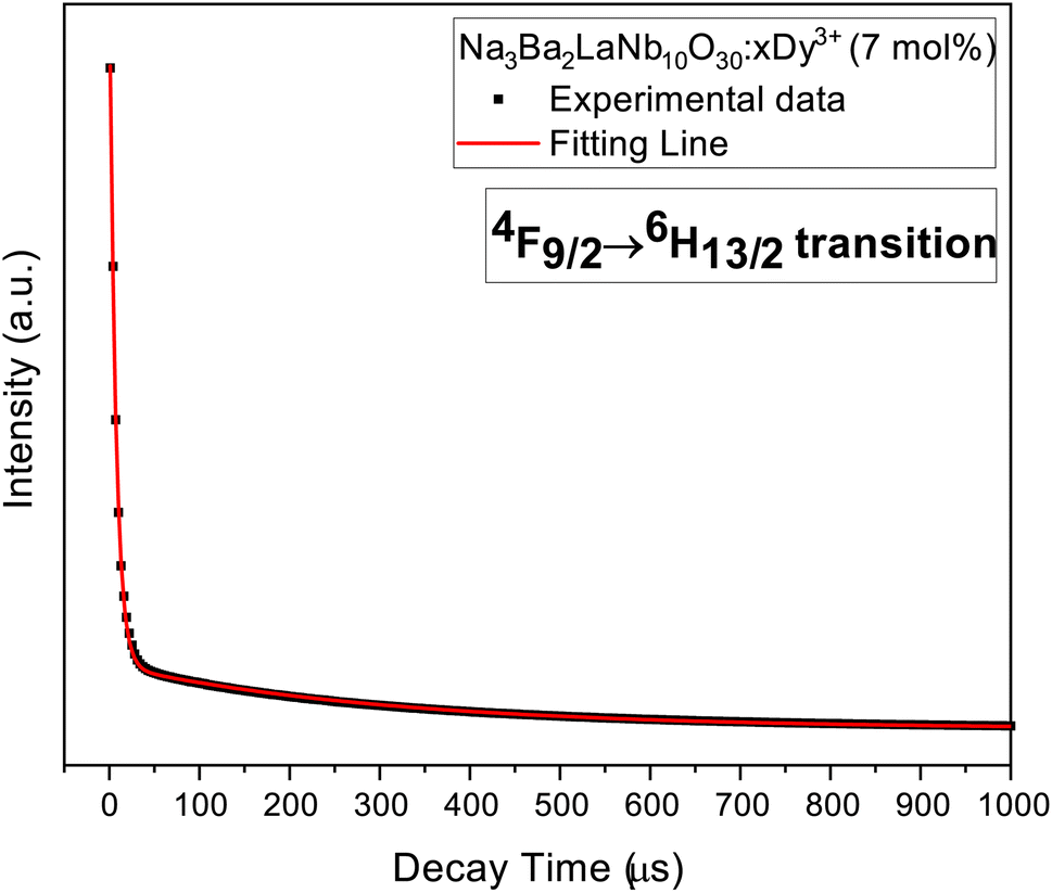
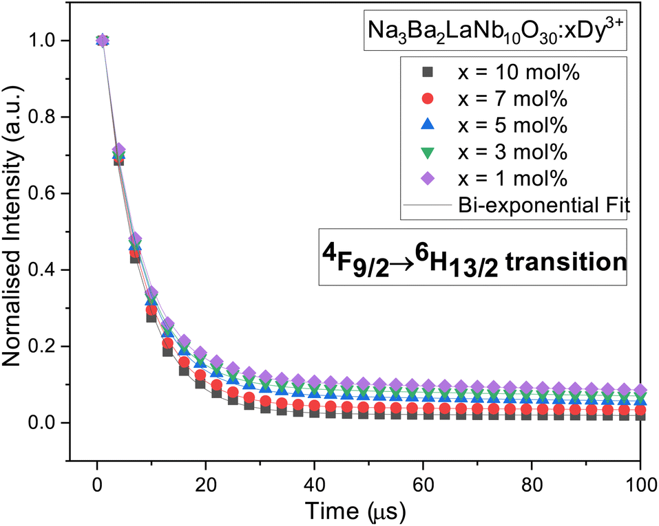
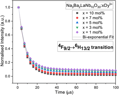
The typical luminous decay curve of Na3Ba2LaNb10O30:xDy3+ (x = 7 mol%) phosphor is presented in Fig. 18. The decay curve to calculate lifetime, for 4F9/2 → 6H13/2 transition under 487 nm excitation, at room temperature for different Dy3+ concentrations, is demonstrated in Fig. 19. It can be seen that, the decay curves fit closely with the double exponential function65,66 shown in eqn (13). The degree of fitting (χ2) was observed to be very close to 1 (∼0.99932).
| |
 | (13) |
where
I0 and
I(
t) signify the phosphorescence intensities at time
t = 0 and some later time
t, respectively.
A1 and
A2 are fitting constants and
τ1 and
τ2 are rapid and slow decay lifetimes.
τavg for different Dy
3+ doped Na
3Ba
2LaNb
10O
30 phosphors were calculated using
eqn (14):
67| |
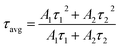 | (14) |
 |
| | Fig. 18 Decay curve 4F9/2 → 6H13/2 transition in Na3Ba2LaNb10O30:xDy3+ (x = 7 mol%) phosphor. | |
 |
| | Fig. 19 Decay curves for 4F9/2 → 6H13/2 transition in Na3Ba2LaNb10O30:xDy3+ (x = 1, 3, 5, 7 and 10 mol%) phosphors. | |
Table 3 summarises the average decay time τavg of different Dy3+ doped Na3Ba2LaNb10O30 phosphors. It is clearly evident that as the Dy3+ ion concentration increases, the τavg of the prepared phosphors gradually decreases from 302.6 μs to 207.4 μs because of energy transfer between adjacent Dy3+ ions.
3.10 Internal quantum yield (IQE) and brightness (B)
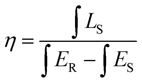
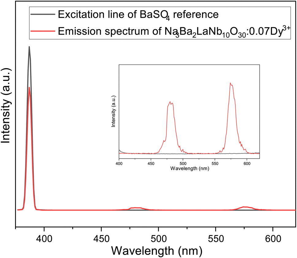
Internal quantum yield (IQE) is an important aspect of a phosphor as it gives the efficiency of conversion of electrical power to observed optical power. The IQE of Na3Ba2LaNb10O30:xDy3+ (x = 7 mol%) phosphor, shown in Fig. 20, was measured using the reference of BaSO4 excitation line. Qualitatively, IQE is the ratio of number of emitted and absorbed photons and can be obtained using the eqn (15):68| |
 | (15) |
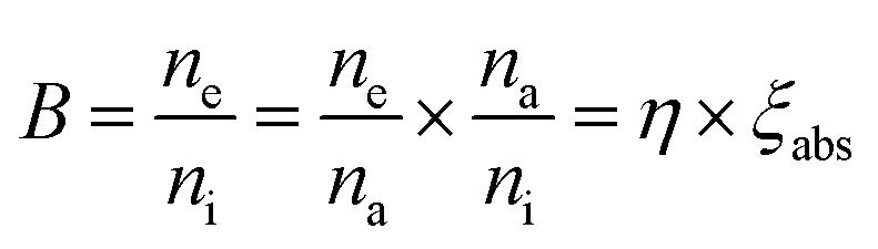
where η represents IQE, LS denotes to the emission spectra of Na3Ba2LaNb10O30:xDy3+ (x = 7 mol%), ES represent phosphor excitation spectra and ER represent excitation exclusively with BaSO4 as reference. IQE (η) of Na3Ba2LaNb10O30:xDy3+ (x = 7 mol%) phosphor was calculated as 45.35% under the excitation of 387 nm, which is significantly higher than previously reported Ca2ZnSi2O7:Dy3+,Eu3+ (IQE: 12.88%),69 LiCaBO3:Dy3+ (IQE: 25.00%)70 and Ca2NaMg2V3O12:Dy3+ (IQE: 25.00%)71 phosphors. Similarly, brightness (B)72 is a dimensionless quantity defined as a parameter that has nothing to do with how sensitive the human eye is and is defined by eqn (16):| |
 | (16) |
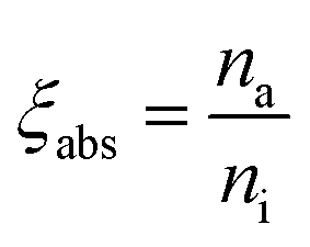
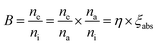
where na, ni and ne correspond to the number of photons absorbed, incident and emitted respectively. Hence absorption efficiency ξabs becomes:| |
 | (17) |
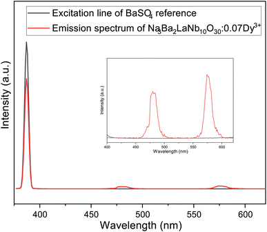 |
| | Fig. 20 Excitation and emission spectra of Na3Ba2LaNb10O30:xDy3+ (x = 7 mol%) phosphor and BaSO4 reference using an integrating sphere for IQE measurement. Inset: enlarged emission spectra (400–630 nm). | |
The calculated value of brightness for Na3Ba2LaNb10O30:xDy3+ (x = 7 mol%) phosphors is 11.41%.
4 Conclusions
In this study, a series of novel white light emitting dysprosium doped Na3Ba2LaNb10O30 phosphors were successfully synthesized through conventional solid-state reaction method. Their structural, morphological, and spectroscopic properties have been investigated for w-LED application using XRD, FE-SEM, FT-IR, steady state and time resolved spectroscopy and quantum yield. X-ray diffractometer confirms that the prepared phosphors were in pure phase, and the crystal system is revealed as filled TTB with P4bm space group. The FE-SEM micrograph reveals that the particle size distribution is in both μm and nm ranges, and the agglomerated particles were of non-uniform shape. Raman and FT-IR spectra indicates the presence of different vibrational modes and functional groups, respectively. Ultraviolet visible diffuse reflectance spectra (UV-DRS) indicates the presence of surface defects in the prepared phosphors. The phosphor emits white light under near-ultraviolet (n-UV) excitation via a dominant mix of blue and yellow emission bands at 481 nm (4F9/2 → 6H15/2) and 575 nm (4F9/2 → 6H13/2), respectively. The optimised concentration of Dy3+ ions beyond which quenching occurs was found to be 7.0 mol%. This concentration quenching mechanism arises due to dipole–dipole interaction. Nephelauxetic ratio and bonding parameters were determined from their luminescent spectra. The CIE chromaticity coordinates, CCT, Y/B ratio and color purity indicates that the synthesised phosphors emits warm white light. The decay time decreases with increasing concentration of Dy3+ ions due to energy transfer between neighbouring Dy3+ ions, as indicated by the lifetime decay curves. The Internal Quantum Yield and Brightness calculated for the optimised phosphor suggests that the prepared phosphor has a potential utility in w-LED application under n-UV excitation.
Author contributions
Kanishk Poria: conceptualization, methodology, writing – original draft. Ravina: conceptualization, methodology, writing – original draft. Sanjana Bhatia: data curation, writing, review, editing. Amit Kumar: formal analysis. Rajwinder Singh: formal analysis. Nisha Deopa: supervision, methodology, software, validation, writing, review, editing, formal analysis. Rajesh Punia: resources. Jangvir Singh Shahi: supervision, methodology, software, validation, writing, review, editing, formal analysis. A. S. Rao: resources, formal analysis.
Conflicts of interest
There are no conflicts to declare.
Acknowledgements
The author (Mr Kanishk Poria) would like to thank Council of Scientific & Industrial Research (CSIR), Govt. of India for providing financial support through Senior Research Fellowship (SRF) (File No. 09/135(0901)/2020-EMR-I, dt. 01/01/2020).
References
- H. Hu and W. Zhang, Opt. Mater., 2006, 28, 536–550 CrossRef CAS.
- M. Djamal, L. Yuliantini, R. Hidayat, K. Boonin, P. Yasaka and J. Kaewkhao, Mater. Today: Proc., 2018, 5, 15126–15130 CAS.
- L. Fan, Y. Shi, Y. Wu, J. Xie, J. Zhang, F. Lei and L. Zhang, J. Lumin., 2017, 190, 504–510 CrossRef CAS.
- S. Verma, K. Verma, D. Kumar, B. Chaudhary, S. Som, V. Sharma, V. Kumar and H. C. Swart, Phys. B Condens. Matter, 2018, 535, 106–113 CrossRef CAS.
- Y. Liu, R. Wang, Q. Yang, G. Li, J. Huang and G. Cai, J. Am. Ceram. Soc., 2022, 105, 6184–6195 CrossRef CAS.
- Y. Liu, X. Liu, W. Wang, B. Zhou and Q. Zhang, Mater. Res. Bull., 2017, 95, 235–242 CrossRef CAS.
- N. Deopa, A. Rao, M. Gupta and G. V. Prakash, Opt. Mater., 2018, 75, 127–134 CrossRef CAS.
- T. Pulli, T. Dönsberg, T. Poikonen, F. Manoocheri, P. Kärhä and E. Ikonen, Light Sci. Appl., 2015, 4, e332 CrossRef CAS.
- M.-H. Fang, C. Ni, X. Zhang, Y.-T. Tsai, S. Mahlik, A. Lazarowska, M. Grinberg, H.-S. Sheu, J.-F. Lee and B.-M. Cheng, et al., ACS Appl. Mater. Interfaces, 2016, 8, 30677–30682 CrossRef CAS PubMed.
- J. Chen, Y. Liu, L. Mei, H. Liu, M. Fang and Z. Huang, Sci. Rep., 2015, 5, 1–9 Search PubMed.
- X. Chen, P. Dai, X. Zhang, C. Li, S. Lu, X. Wang, Y. Jia and Y. Liu, Inorg. Chem., 2014, 53, 3441–3448 CrossRef CAS PubMed.
- K. Jha, A. K. Vishwakarma, M. Jayasimhadri and D. Haranath, J. Alloys Compd., 2017, 719, 116–124 CrossRef CAS.
- K. Shinde and S. Dhoble, Crit. Rev. Solid State Mater. Sci., 2014, 39, 459–479 CrossRef CAS.
- M. Shi, L. Yao, J. Xu, C. Liang, Y. Dong and Q. Shao, J. Am. Ceram. Soc., 2021, 104, 3279–3288 CrossRef CAS.
- P. Dang, G. Li, X. Yun, Q. Zhang, D. Liu, H. Lian, M. Shang and J. Lin, Light Sci. Appl., 2021, 10, 1–13 CrossRef PubMed.
- M. Tshabalala, F. Dejene, S. S. Pitale, H. Swart and O. Ntwaeaborwa, Phys. B Condens. Matter, 2014, 439, 126–129 CrossRef CAS.
- N. Lakshminarasimhan and U. Varadaraju, J. Electrochem. Soc., 2005, 152, H152 CrossRef CAS.
- G. Hu, S. Yi, Z. Fang, Z. Hu and W. Zhao, Opt. Mater., 2019, 98, 109428 CrossRef CAS.
- F. Xiong, F. Xu, H. Lin, Y. Wang, E. Ma and W. Zhu, Appl. Phys. A, 2020, 126, 1–8 CrossRef.
- Z. Li, Y. Hua and G. Ou, Optik, 2021, 233, 166595 CrossRef CAS.
- P. Wang, L. Schwertmann, R. Marschall and M. Wark, J. Mater. Chem. A, 2014, 2, 8815–8822 RSC.
- Y. Ma, R. Liu, X. Geng, X. Hu, W. Chen, B. Deng, R. Yu and H. Geng, Ceram. Int., 2022, 48, 4080–4089 CrossRef CAS.
- G. Zhu, Z. Ci, S. Xin, Y. Wen and Y. Wang, Mater. Lett., 2013, 91, 304–306 CrossRef CAS.
- T. Wei, Y. Wang, Q. Zhou, Z. Li, L. Zhan and Q. Jin, Ceram. Int., 2014, 40, 16647–16651 CrossRef CAS.
- C.-J. Chan, F. F. Lange, M. Rühle, J.-F. Jue and A. V. Virkar, J. Am. Ceram. Soc., 1991, 74, 807–813 CrossRef CAS.
- R. Jain, R. Sinha, M. K. Sahu and M. Jayasimhadri, J. Lumin., 2021, 36, 1444–1451 CrossRef CAS PubMed.
- B. M. Mothudi, O. Ntwaeaborwa, S. S. Pitale and H. Swart, J. Alloys Compd., 2010, 508, 262–265 CrossRef CAS.
- P. Babu, K. H. Jang, E. S. Kim, L. Shi, H. J. Seo and F. Lopez, J. Korean Phys. Soc., 2009, 54, 1488–1491 CrossRef CAS.
- S. K. Gupta, M. Kumar, V. Natarajan and S. Godbole, Opt. Mater., 2013, 35, 2320–2328 CrossRef CAS.
- M. K. Sahu and J. Mula, J. Am. Ceram. Soc., 2019, 102, 6087–6099 CrossRef CAS.
- L. Fang, H. Zhang, J. Yang, F. Meng and R. Yuan, J. Mater. Sci. Lett., 2003, 22, 1705–1707 CrossRef CAS.
- L. Sun, B. Devakumar, J. Liang, B. Li, S. Wang, Q. Sun, H. Guo and X. Huang, RSC Adv., 2018, 8, 31835–31842 RSC.
- L. Alexander and H. P. Klug, J. Appl. Phys., 1950, 21, 137–142 CrossRef CAS.
- K. Rawat and P. Shishodia, Adv. Powder Technol., 2017, 28, 611–617 CrossRef CAS.
- M. Bouziane, M. Taibi, L. Saviot and A. Boukhari, Phys. B Condens. Matter, 2011, 406, 4257–4260 CrossRef CAS.
- R. E. Wilde, J. Raman Spectrosc., 1991, 22, 321–325 CrossRef CAS.
- A. Boudou and J. Sapriel, Phys. Rev. B: Condens. Matter Mater. Phys., 1980, 21, 61 CrossRef CAS.
- S. Jana, A. Mondal, J. Manam and S. Das, J. Alloys Compd., 2020, 821, 153342 CrossRef CAS.
- H. Kabir, S. H. Nandyala, M. M. Rahman, M. A. Kabir and A. Stamboulis, Appl. Phys. A, 2018, 124, 1–11 CrossRef CAS.
- M. Salavati-Niasari, G. Hosseinzadeh and F. Davar, J. Alloys Compd., 2011, 509, 134–140 CrossRef CAS.
- M. Afqir, A. Tachafine, D. Fasquelle, M. Elaatmani, J.-C. Carru, A. Zegzouti, M. Daoud, S. Sayouri, T.-d. Lamcharfi and M. Zouhairi, Process. Appl. Ceram., 2018, 12, 72–77 CrossRef CAS.
- H. Bruncková, L. Medveckỳ, P. Hvizdoš, J. Ďurišin and V. Girman, J. Mater. Sci., 2015, 50, 7197–7207 CrossRef.
- I. P. Sahu, D. Bisen, N. Brahme and R. K. Tamrakar, J. Electron. Mater., 2016, 45, 2222–2232 CrossRef CAS.
- M. Jiao, C. Yang, M. Liu, Q. Xu, Y. Yu and H. You, Opt. Mater. Express, 2017, 7, 2660–2671 CrossRef CAS.
- W. Carnall, P. Fields and K. Rajnak, J. Chem. Phys., 1968, 49, 4424–4442 CrossRef CAS.
- K. Poria, N. Deopa and J. S. Shahi, Laser Sci., 2022, JW5A1 Search PubMed.
- Q. Su, Z. Pei, L. Chi, H. Zhang, Z. Zhang and F. Zou, J. Alloys Compd., 1993, 192, 25–27 CrossRef CAS.
- L. Mishra, A. Sharma, A. K. Vishwakarma, K. Jha, M. Jayasimhadri, B. Ratnam, K. Jang, A. Rao and R. Sinha, J. Lumin., 2016, 169, 121–127 CrossRef CAS.
- C. Jorgensen, Prog. Inorg. Chem., 1962, 4, 73–124 Search PubMed.
- N. Deopa and A. Rao, J. Lumin., 2017, 192, 832–841 CrossRef CAS.
- G. Blasse, Phys. Lett. A, 1968, 28, 444–445 CrossRef CAS.
- L. Van Uitert, J. Electrochem. Soc., 1967, 114, 1048 CrossRef CAS.
- D. L. Dexter and J. H. Schulman, J. Chem. Phys., 1954, 22, 1063–1070 CrossRef CAS.
- D. L. Dexter, J. Chem. Phys., 1953, 21, 836–850 CrossRef CAS.
- S. Kaur, A. Rao and M. Jayasimhadri, Ceram. Int., 2017, 43, 7401–7407 CrossRef CAS.
- A. K. Vishwakarma, K. Jha, M. Jayasimhadri, B. Sivaiah, B. Gahtori and D. Haranath, Dalton Trans., 2015, 44, 17166–17174 RSC.
- J. S. Kumar, K. Pavani, A. M. Babu, N. K. Giri, S. Rai and L. R. Moorthy, J. Lumin., 2010, 130, 1916–1923 CrossRef CAS.
- F. Miller, A. Vandome and M. John, CIE 1931 Color Space, VDM Publishing, 2010 Search PubMed.
- M. N. Khan, Understanding LED illumination, CRC Press, 2013 Search PubMed.
- C. S. McCamy, Color Res. Appl., 1992, 17, 142–144 CrossRef.
- B. Ratnam, M. Jayasimhadri, K. Jang, H. Sueb Lee, S.-S. Yi and J.-H. Jeong, J. Am. Ceram. Soc., 2010, 93, 3857–3861 CrossRef CAS.
- P. Nayak, S. S. Nanda, S. K. Gupta, K. Sudarshan and S. Dash, J. Am. Ceram. Soc., 2022, 105, 7384–7398 CrossRef CAS.
- S. Sharma, N. Brahme, D. Bisen and P. Dewangan, Opt. Express, 2018, 26, 29495–29508 CrossRef CAS PubMed.
- I. P. Sahu, D. Bisen and N. Brahme, Displays, 2014, 35, 279–286 CrossRef CAS.
- K. Li, X. Liu, Y. Zhang, X. Li, H. Lian and J. Lin, Inorg. Chem., 2015, 54, 323–333 CrossRef CAS PubMed.
- K. Jha and M. Jayasimhadri, J. Am. Ceram. Soc., 2017, 100, 1402–1411 CrossRef CAS.
- J. Sun, X. Zhang, Z. Xia and H. Du, Mater. Res. Bull., 2011, 46, 2179–2182 CrossRef CAS.
- S. Wang, Y. Xu, T. Chen, W. Jiang, J. Liu, X. Zhang, W. Jiang and L. Wang, Chem. Eng. J., 2021, 404, 125912 CrossRef CAS.
- K. Mondal and J. Manam, J. Lumin., 2018, 195, 259–270 CrossRef CAS.
- A. R. Beck, S. Das and J. Manam, J. Mater. Sci.: Mater. Electron., 2017, 28, 17168–17176 CrossRef CAS.
- L. Yang, X. Mi, H. Zhang, X. Zhang, Z. Bai and J. Lin, J. Alloys Compd., 2019, 787, 815–822 CrossRef CAS.
- P. A. Tanner, L. Zhou, C. Duan and K.-L. Wong, Chem. Soc. Rev., 2018, 47, 5234–5265 RSC.
|
| This journal is © The Royal Society of Chemistry 2023 |
Click here to see how this site uses Cookies. View our privacy policy here. 
 Open Access Article
 This Open Access Article is licensed under a Creative Commons Attribution-Non Commercial 3.0 Unported Licence
 a,
Ravina Lohanb,
Sanjana Bhatiaa,
Amit Kumarb,
Rajwinder Singha,
Nisha Deopa
a,
Ravina Lohanb,
Sanjana Bhatiaa,
Amit Kumarb,
Rajwinder Singha,
Nisha Deopa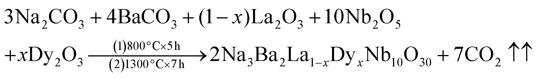


 is the inverse slope line.