
 Open Access Article
 This Open Access Article is licensed under a Creative Commons Attribution-Non Commercial 3.0 Unported Licence
Green preparation of silver nanocluster composite AgNCs@CF-g-PAA and its application: 4-NP catalytic reduction and hydrogen production†
Fei Hanab,
Wenrui Wangab,
Danyi Liab,
Siyi Xuab,
Ying Sunab,
Lin Linab,
Lin Maab,
Jihao Li *abc and
Linfan Li*abc
*abc and
Linfan Li*abc
aShanghai Institute of Applied Physics, Chinese Academy of Sciences, Shanghai 201800, China. E-mail: lilinfan@sinap.ac.cn; lijihao@sinap.ac.cn
bUniversity of Chinese Academy of Sciences, Beijing 100049, China
cWuwei Institute of New Energy, Gansu 733000, China
First published on 17th April 2023
Abstract
4-Nitrophenol (4-NP) is a serious organic environmental pollutant. Conversion of 4-nitrophenol to 4-aminophenol (4-AP) by catalytic hydrogenation is an effective solution. In this work, a catalyst (AgNCs@CF-g-PAA) loaded with silver nanoclusters (AgNCs) was prepared by radiation technique. Firstly, the template polyacrylic acid (PAA) was grafted onto the cotton fiber (CF) by radiation grafting technique to obtain a solid template (CF-g-PAA). After that, AgNCs were synthesized in situ on CF-g-PAA by radiation reduction, and the composite material AgNCs@CF-g-PAA was obtained directly. AgNCs@CF-g-PAA has an obvious photoluminescence phenomenon, which is attributed to the stable AgNCs binding to the carboxyl on the PAA molecular chain. Due to the extremely small size of AgNCs, AgNCs@CF-g-PAA has good catalytic characteristics. The prepared AgNCs@CF-g-PAA catalyst has a very high catalytic rate for the hydrogenation of 4-NP. Even at high concentrations of 4-NP, AgNCs@CF-g-PAA can still maintain a high catalytic rate. At the same time, the AgNCs@CF-g-PAA catalyst can also be used to catalyze the rapid hydrolysis of sodium borohydride, which is conducive to hydrogen production. In summary, we have prepared a practical catalyst AgNCs@CF-g-PAA with high catalytic performance based on cheap raw materials and a simple synthesis route, which provides a catalyst candidate for the treatment of water contaminant 4-NP and the production of hydrogen from sodium borohydride.
1 Introduction
With the development of society and the expansion of agriculture and industry, the problem of water shortage becomes more and more serious.1,2 The lack of clean, fresh water has brought about many problems worldwide.3,4 In the future, as the population increases and living standards improve, the problem of water scarcity will become more serious.5 At present, water pollution caused by the discharge of pollutants produced by industry is one of the causes of water shortage, especially organic pollutants.6 4-Nitrophenol (4-NP) is an intermediate mainly used in pesticides, medicine, dyes and other fine chemicals.7 Due to its carcinogenicity and difficulty in natural decomposition, 4-NP produced from industrial wastewater or pesticide decomposition can cause serious water pollution when released into the environment.8 Therefore, it is very important to develop an efficient and simple technology to remove 4-NP before it is discharged into the environment with industrial wastewater.So far, many viable methods for removing 4-NP have been explored and developed, such as physical adsorption,9,10 photocatalytic oxidation,11 catalytic reduction12 and so on. Among them, the catalytic reduction of 4-NP by metal nanoparticles (MNPs) has been widely concerned in the field of sustainable chemical industry due to its excellent catalytic performance.12,13 At present, researchers have developed different catalytic materials by taking advantage of the characteristics of small particle size and high specific surface area of metal nanoparticles, which bring high catalytic activity. He, ZM et al. synthesized gold nanoparticles stabilized by konjac glucomannan for catalytic reduction of 4-NP.14 Delekar, S. D. et al. synthesized titanium dioxide loaded with Ni nanoparticles for catalytic hydrogenation of 4-NP.15 Mitchell R. M. Bruce. et al. synthesized AuNPs-COOH catalysts with high catalytic rates for 4-NP in complex environments.16 The smaller particle size of nanoparticles plays an important role in the realization of catalytic function.
Metal nanoclusters (MNCs), such as silver nanoclusters (AgNCs) and gold nanoclusters (AuNCs), tend to have smaller particle sizes and should be able to exhibit higher catalytic activity than metal nanoparticles.17,18 Because of the smaller particle size, the nanoclusters have a stronger tendency to spontaneously aggregate, in order to reduce the surface energy.19 Different template molecules are used to stabilize metal nanoclusters to keep their size small, such as polymers,20 amino acids,21 DNA,22 etc. However, it is difficult to obtain only metal nanoclusters in solution state to meet the requirement of catalyst separability in industrial wastewater treatment.
Cotton fiber (CF) is an important renewable biopolymer, with applications ranging from textiles to medicine, which is the richest natural polymer around the globe.23–25 The fabric structure of the cotton fiber membrane provides a large specific surface area and support structure for the catalytic material.23,26 This makes the cotton fiber membrane can be a good catalyst carrier. However, it is difficult to load silver nanoclusters with pure cotton fiber because of the lack of corresponding template units. Radiation technique is often used for radiation modification of polymer materials because of its simple experimental conditions, mild reaction and easy control.27 Considering the non-selective nature of gamma-ray interactions,27 radiation grafting techniques allow the grafting of vinyl monomers onto a variety of polymer substrates without the need for initiators and specific functional groups.28 Cotton fiber material is one of the matrix materials commonly used for radiation modification.29,30 Acrylic acid monomer is also a vinyl monomer widely used for polymer radiation modification.28,31 In our previous work, we have successfully prepared silver nanoclusters using PAA as templates using radiation reduction technology.32 Furthermore, cotton fiber can be modified by radiation technology to make it capable of carrying silver nanoclusters for excellent catalytic properties. This coupling effect of chemical composition and physical structure is conducive to giving the material excellent properties.33 The low cost and high efficiency of catalytic materials are met by radiation technology and low-cost materials.
Nowadays, hydrogen energy is getting a lot of attention because it is clean and has no greenhouse gas emissions.34–38 Many hydrogen-containing substances are used to produce hydrogen.39–41 Sodium borohydride is a common cyanide, which is an excellent candidate for hydrogen production due to its characteristics of high hydrogen content, fast reaction, easy regeneration, low toxicity and non-flammability.42,43 El-Halwany, M. M. et al. prepared Ni–Co@PVDF-HFP NFs catalyst material for hydrolyzing sodium borohydride to produce hydrogen. For the excellent catalytic performance brought by small particle size, AgNCs maybe also catalyze the hydrolysis of sodium borohydride and achieve efficient hydrogen production. The preparation of low-cost catalytic materials also offers a simple and efficient potential method for hydrogen production.
In this work, we prepared silver nanoclusters composite cotton fiber material grafted with polyacrylic acid (PAA) by a two-step synthesis using radiation technique. Firstly, cotton fibers (CF-g-PAA) grafted with PAA were prepared by method of immersion using radiation grafting technique. The abundant carboxyl s on the modified CF-g-PAA provide sufficient sites for the loading of silver nanoclusters. Next, using CF-g-PAA as a template, silver nanoclusters were in situ reduced to CF-g-PAA by radiation reduction, and finally silver nanocluster composites (AgNCs@CF-g-PAA) were obtained directly. The loading degree of Ag nanoclusters can be simply controlled by controlling the reaction conditions. At the same time, the binding effect of silver nanoclusters with the material is also clearly elaborated. Based on the excellent catalytic activity brought by silver nanoclusters, the AgNCs@CF-g-PAA can efficiently catalyze 4-NP reduction and hydrogen production from sodium borohydride. At the same time, because AgNCs is bound to the matrix material, the existence of CF-g-PAA ensures that the catalyst is easy to separate and convenient for practical application.
2 Experimental
2.1 Reagents and materials
Acrylic acid (AA), silver nitrate, isopropyl alcohol, sodium borohydride and 4-nitrophenol (4-NP) were all purchased from Sinopharm Chemical Reagent Co. Ltd. (Shanghai, China). All chemicals and solvents were analytical reagent (AR). All chemicals and solvents were used as received without further purification. Cotton fiber membrane (CF) used in the experiment is commercial cotton fiber membrane material. The water used throughout all experiments was purified through a Millipore system.2.2 Instrumentation
Ultraviolet-visible spectrum were carried out on a HITACHI U-3900 UV-vis spectrophotometer. Fluorescence spectrum were performed on a Spectrofluorometer FS5. The IR analysis was performed with a FTIR650 spectrophotometer over the range 600–4000 cm−1 at a resolution of 2 cm−1. For the FESEM imaging study, A JSM-6700F FESEM instrument was used to capture the SEM images at an accelerating voltage of 10–15 kV. Meanwhile, EDS images were collected at an accelerating voltage of 15 kV. Microscopic photographs of materials are obtained through a microscope. The valence analysis of element on the film surface was collected by SCIENTIFICESCALAB 250Xi (XPS) and fitted by software. In order to study the thermal properties of the material, TG 209F4 was used to test the thermogravimetric property of the material.2.3 Preparation of CF-g-PAA
CF-g-PAA was prepared by method of immersion through radiation grafting. 10.8 g of acrylic acid is dissolved into 30 mL of deionized water by ultrasonic to obtain the immersion solution. The CF of a certain size was immersed in the immersion solution and shaken for 1 h. The CF adsorbed to the immersion solution is then taken out and gently pressed to remove the excess solution. Finally, CF is placed in a sealed bag and sealed by vacuum, and then radiated at 20 kGy absorbed doses through 60Co. The total synthesis process was conducted at room temperature. After radiation, the CF after graft modification (CF-g-PAA) was ultrasonic cleaned with deionized water for 15 min, during which the deionized water should be replaced three times. The membranes were dried in an oven at 60 °C for 24 hours and then weighed. The degree of grafting (DG) was determined as the percentage increase in the film weight according to eqn (1):
 | (1) |
2.4 Preparation of AgNCs@CF-g-PAA
AgNCs@CF-g-PAA was prepared by radiation reduction. 0.1 M silver nitrate-deionized water solution was prepared. After that, isopropyl alcohol was added to the solution and configured as a loaded solution with a concentration of 0.5 M. Subsequently, the prepared CF-g-PAA was immersed in the loaded solution and shaken for 2 h. After that, the solution was sparged with N2 for 15 minutes, and then radiated at 20 kGy absorbed doses through 60Co. After radiation, the CF-g-PAA after loading AgNCs (AgNCs@CF-g-PAA) was ultrasonic cleaned with deionized water for 6 min. The washed AgNCs@CF-g-PAA is naturally dried at room temperature and stored in the refrigerator at 4 °C for later use. The degree of loading (DL) was determined as the percentage increase in the film weight according to eqn (2):
 | (2) |
2.5 Catalysis performance of AgNCs@CF-g-PAA
20 mL solution of 0.5 × 10⁻³ M 4-nitrophenol (4-NP) is prepared by dissolving 4-NP in deionized water. 10 mL of sodium borohydride solution with a concentration of 0.5 M was added to the solution to get a catalytic solution. The prepared AgNCs@CF-g-PAA was cut into 1.5 × 2 cm pieces and put into the catalytic solution for the catalytic reaction under the condition of standing. At intervals, a certain amount of samples are taken from the system and tested for UV-vis spectra. All the experiments were conducted at room temperature.2.6 Cyclic catalytic performance of AgNCs@CF-g-PAA
40 mL solution of 0.5 × 10⁻³ M 4-nitrophenol (4-NP) is prepared by dissolving 4-NP in deionized water. 20 mL of sodium borohydride solution with a concentration of 0.5 M was added to the solution to get a catalytic solution. 10 mL of the catalyst solution is poured into the glass bottle containing the catalyst AgNCs@CF-g-PAA for catalysis. After 5 min of catalysis, appropriate solution was taken for UV-VIS spectrum test, and conversion rate was calculated according to eqn (3). The process was then repeated four times with a new catalytic solution.
 | (3) |
2.7 Hydrogen production performance of AgNCs@CF-g-PAA
0.3 g sodium borohydride was dissolved in deionized water and configured into a hydrogen production solution with a mass fraction of 1%. The prepared AgNCs@PE-g-PAA was cut into 1.5 × 2 cm pieces and put into hydrogen production solution to catalyze the hydrolysis of sodium borohydride. The hydrogen was collected by drainage and the volume of hydrogen was recorded every five minutes until 90 minutes. All the experiments were conducted at room temperature. After the reaction for 90 minutes, the catalyst was recovered.3 Results and discussion
3.1 Preparation of AgNCs@CF-g-PAA
The modified cotton fiber membrane material with polyacrylic acid (PAA) chains and silver nanoclusters (AgNCs) was prepared by a two-step process using radiation technology. As shown in Fig. 1, in the first step, the radiation grafting technique was used to initiate the graft polymerization of acrylic acid (AA) on the cotton fiber (CF), and the cotton fiber (CF-g-PAA) grafted modified by PAA was obtained. Since the carboxyl can coordinate with silver atoms, silver ions are in situ reduced on CF-g-PAA by radiation reduction. Using the carboxyl on the PAA molecular chain as the template, silver nanocluster composites (AgNCs@CF-g-PAA) loaded with silver nanoclusters are obtained.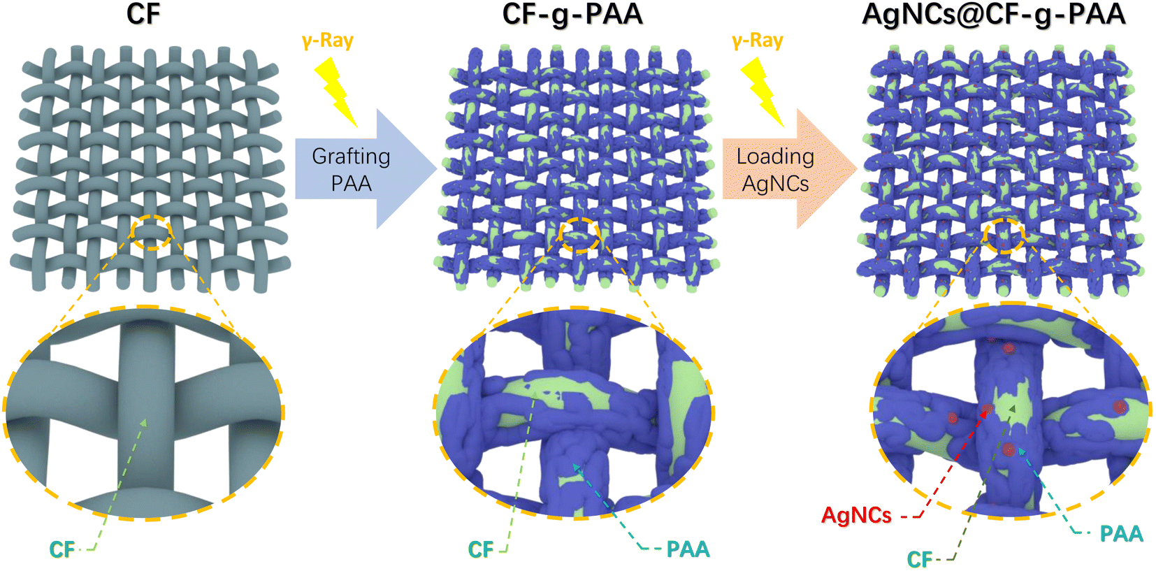 | ||
| Fig. 1 The synthetic route of AgNCs@CF-g-PAA. | ||
Fig. 2(a) shows the changes in functional groups of materials during the synthesis process. After grafting PAA, CF-g-PAA showed an absorption peak from the carboxyl at 1700 cm−1, which was derived from the PAA molecular chain. This proved the successful preparation of CF-g-PAA. After further loading of AgNCs, a new absorption peak appeared at 1520 cm−1 (Fig. 2(a)), which may be attributed to carboxylate. The appearance of carboxylate here may be related to the interaction between carboxylate groups and silver nanoclusters. Because of the photoluminescence ability, silver nanoclusters can absorb specific wavelengths of light. Neither CF nor CF-g-PAA can absorb any light at 300–800 nm wavelength (Fig. 2(b)). However, there is a weak absorption at 500 nm in ultraviolet-visible spectrum of AgNCs@CF-g-PAA, which comes from the loaded AgNCs (Fig. 2(b)). The 500 nm absorption peak is thought to be attributed to silver nanoclusters using carboxyl as template unit in other works.20 At the same time, there is no diffraction peak of silver nanoparticles at AgNCs@CF-g-PAA (Fig. S1†). This suggests that the silver nanoclusters are indeed being loaded onto AgNCs@CF-g-PAA. More direct evidence comes from the fluorescence spectrum of AgNCs@CF-g-PAA (Fig. 2(c)). As we all know, AgNCs are distinguished from nanoparticles by their photoluminescence, due to their extremely small size.19 As shown in the figure (Fig. 2(c)), AgNCs@CF-g-PAA produces a 625 nm fluorescence emission when excited by light at 520 nm wavelength. That means AgNCs are synthesized. AgNCs@CF-g-PAA has a quantum yield of 1.96% and a fluorescence lifetime of 0.07 ns (Fig. S3†). The nanosecond fluorescence lifetime also indicates that the photoluminescence of AgNCs@CF-g-PAA is a fluorescence emission, rather than phosphorescent emission with a longer fluorescence lifetime. It is worth noting that the fluorescence emission of AgNCs in the prepared AgNCs@CF-g-PAA is obviously dependent on excitation wavelength. With the increase of excitation wavelength, the fluorescence emission of AgNCs@CF-g-PAA shows obvious red shift (Fig. S2†). This can be explained by the fact that the AgNCs prepared by radiation reduction are mixed by silver nanocluster with different numbers of silver atoms. This phenomenon has been seen in our previous work32 and other work,44 which preparation of silver nanoclusters use polymer templates.
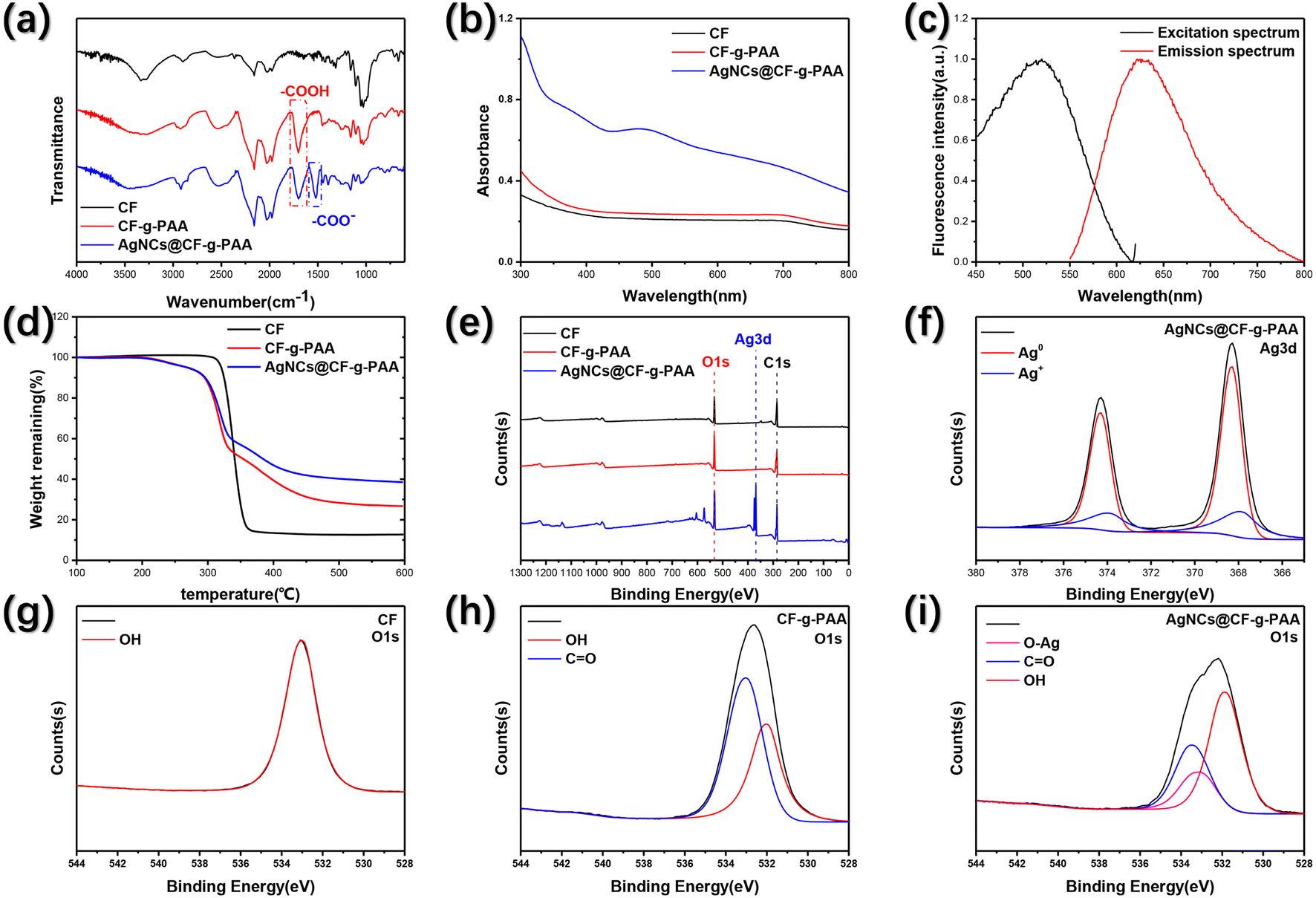 | ||
| Fig. 2 (a), Fourier Transform Infrared Spectroscopy of CF, CF-g-PAA, AgNCs@CF-g-PAA; (b) ultraviolet visible spectrum of CF, CF-g-PAA, AgNCs@CF-g-PAA; (c) fluorescence spectrum of AgNCs@CF-g-PAA; (d) thermal weight loss curve of CF, CF-g-PAA, AgNCs@CF-g-PAA; (e) XPS spectrum of CF, CF-g-PAA, AgNCs@CF-g-PAA; (f) XPS Ag3d spectrum of AgNCs@CF-g-PAA; (g) XPS O 1s spectrum of CF; (h) XPS O 1s spectrum of CF-g-PAA; (i) XPS O 1s spectrum of AgNCs@CF-g-PAA. | ||
Fig. 2(d) shows the thermal properties of the material. For CF without any modification, the thermal decomposition temperature is 340 °C, and only 12% of the thermal decomposition products remain at 600 °C (Fig. 2(d)). After grafting PAA, when the temperature reached 200 °C, the carboxyl of CF-g-PAA began to decarboxylate, and the PAA gradually decomposed with the increase of temperature. In this process, when the temperature reaches the thermal decomposition temperature of CF, CF also starts thermal decomposition, resulting in rapid increase of weightlessness. When the temperature reaches 600 °C, the residual mass of CF-g-PAA is higher than that of CF, reaching 27%. After loading AgNCs, the thermal decomposition behavior of AgNCs@CF-g-PAA is almost the same as that of CF-g-PAA. The only difference is that AgNCs@CF-g-PAA has a higher residual mass of 38%, attributed to residual silver material. The thermal decomposition residual mass differences of AgNCs@CF-g-PAA and CF-g-PAA are also consistent with the degree of loading calculated by mass difference of the sample. Due to the ease of control of radiation technology, the degree of loading of AgNCs in AgNCs@CF-g-PAA can be controlled simply by controlling reaction conditions (Fig. S4†). Among them, controlling the concentration of silver ions can more directly and effectively control the degree of loading of AgNCs (Fig. S4(a)†). At the same time, lower absorbed dose, appropriate degree of grafting of CF-g-PAA and appropriate isopropyl alcohol concentration were more conducive to the formation of AgNCs (Fig. S4(b)–(d)†). Similarly, CF-g-PAA grafted to different degrees of PAA can be prepared by controlling reaction conditions (Fig. S5†). Among them, controlling AA concentration is easier to achieve the preparation of CF-g-PAA with different degree of grafting. This illustrates the simple synthesis and control of AgNCs@CF-g-PAA preparation using radiation techniques.
Due to the very small particle size, AgNCs often need to rely on template materials to exist stably.17 The oxygen of carboxyl in PAA molecular chain can produce coordination effect on metal atoms, which is beneficial to the stabilization of AgNCs. XPS was used to define the interaction between AgNCs and template PAA of AgNCs@CF-g-PAA. As shown in the figure (Fig. 2(e)), the original CF contains only C element and O element, which are derived from the carbon chain skeleton and the hydroxyl group on molecular chain. After grafting PAA, CF-g-PAA still showed the presence of C element and O element in the total spectrum (Fig. 2(e)). However, in O 1s spectrum, CF-g-PAA has both –OH and –COOH states of O element (Fig. 2(h)), while CF only has O element in –OH (Fig. 2(g)). In particular, the O element of –COOH belongs to the carboxyl of PAA molecular chain. After loading AgNCs, AgNCs@CF-g-PAA show the presence of the Ag element (Fig. 2(e)). It is more clear from the Ag 3d spectrum (Fig. 2(f)) that the Ag element in AgNCs@CF-g-PAA is mainly Ag0, indicating that Ag+ ion has been successfully reduced to form AgNCs. Fig. S6† visually shows the elemental composition of the material. It is worth noting that in the O 1s spectrum (Fig. 2(i)) of AgNCs@CF-g-PAA, the O element produces a new peak, showing a new chemical state, which can be caused by the combination between carboxyl group of PAA and AgNCs. This shows that the PAA does act as a template unit and does stabilize the AgNCs onto the substrate material.
The morphology and element distribution of the materials were studied by microscope, SEM and EDS. As shown in the figure (Fig. 3(a)), the original CF exhibits a braided structure, giving it a large surface area. After grafted PAA and loaded AgNCs, the braided structure of cotton fibers was not affected (Fig. 3(a)). This helps to keep the substrate material high surface area. Fig. 3(b) shows a more detailed morphology of the material. Each beam in the CF braided structure consists of a monofilament. After grafting PAA, the morphology of monofilaments of AgNCs@CF-g-PAA did not change significantly, but there was a slight mutual adhesion between monofilaments in each bundle of fibers that constituted the braided structure (Fig. 3(b)). It can be seen from the image (Fig. 3(a) and (b)) that the adhesion between monofilaments only occurs within a bundle of fibers, and has little impact on the overall knitting structure. After further loading of AgNCs, the morphology of AgNCs@CF-g-PAA did not change significantly (Fig. 3(b)). However, in SEM images (Fig. 3(c)) with higher magnification, there are tiny protrusions on the surface of monofilaments of AgNCs@CF-g-PAA. As can be seen from the EDS image (Fig. 3(c)), the uniform distribution of Ag element on the surface of AgNCs@CF-g-PAA indicates that AgNCs is well dispersed on the surface of the material. At the same time, EDS images (Fig. 3(c)) of cross sections also showed that AgNCs were distributed in the monofilament, and distributed evenly along the radial direction. This fully demonstrates that while maintaining the original morphological characteristics of CF, AgNCs is uniformly loaded onto the surface and inside of the material. This proves that the material preserves the high surface area structure of the original material while the active site was obtained. By combining the advantages of both, this facilitates the material to achieve high catalytic performance.
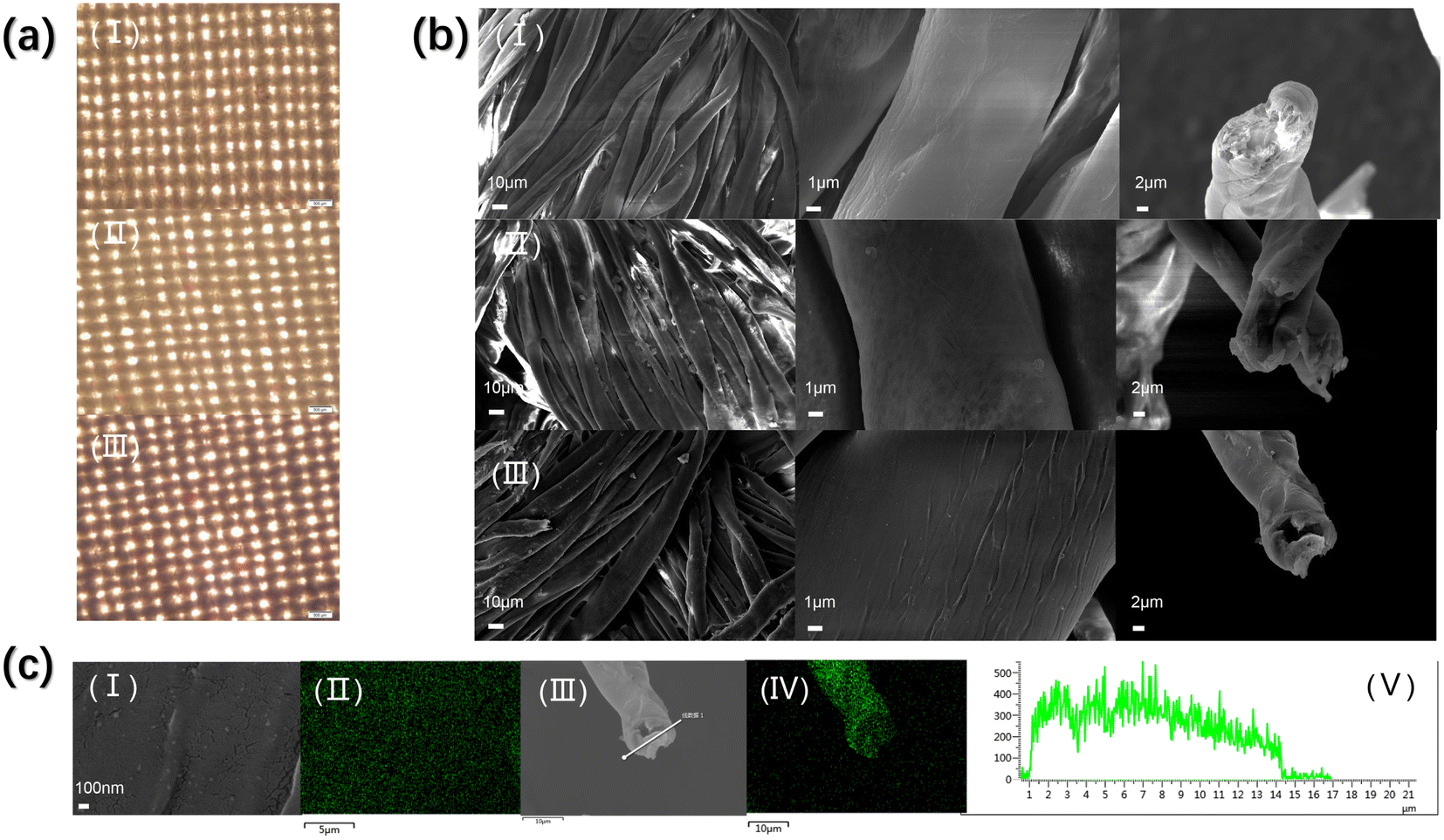 | ||
| Fig. 3 (a) Microscope photograph: (I) CF, (II) CF-g-PAA, (III) AgNCs@CF-g-PAA; (b) SEM image: (I) CF, (II) CF-g-PAA, (III) AgNCs@CF-g-PAA; (c) high resolution SEM image and EDS image of AgNCs@CF-g-PAA (I) high resolution SEM image, (II) EDS distribution of silver elements of surface, (III) EDS electronic image of cross section, (IV) EDS distribution of silver elements of cross section, (V) line scan EDS of silver elements. | ||
3.2 Catalysis performance of AgNCs@CF-g-PAA
4-Nitrophenol (4-NP), widely used in industrial fields, is an important water pollutant.9,45,46 Using AgNCs to transform the harmful 4-NP into 4-aminophenol (4-AP), a precursor in the field of medicine, is an effective solution. As shown in the figure (Fig. 4(a)), 4-NP solution is a yellow clarified solution without the addition of catalyst AgNCs@CF-g-PAA. After adding AgNCs@CF-g-PAA, 4-NP solution gradually becomes colorless, indicating that the material has obvious catalytic effect on 4-NP reductive hydrogenation (Fig. 4(a)). The catalytic process can be seen in detail in movie S1† (the video is processed at 8× fast forward). As can be seen from the video, after the addition of the catalyst AgNCs@CF-g-PAA, the 4-NP solution gradually changed from obvious yellow to colorless transparent within 10 minutes. The catalytic process was further evaluated by ultraviolet-visible spectroscopy. With the addition of AgNCs@CF-g-PAA, the absorption peak of 4-NP at 400 nm gradually weakened, and that of 4-AP at 300 nm gradually increased (Fig. 4(a)). The 96% conversion rate of 4-NP can be achieved in about 6 min. The catalytic rate of AgNCs@CF-g-PAA was evaluated by pseudo first order fitting curve. AgNCs@CF-g-PAA has a high rate constant of 0.00861 s−1, indicating that the efficient catalysis of 4-NP can be achieved. The transfer of electrons from the donor sodium borohydride to the acceptor 4-NP is crucial in the 4-NP to 4-AP conversion.47,48 In this process, AgNCs can accelerate the electron transfer and catalyze the hydroreduction of 4-NP.49 Here, the catalytic mechanism of AgNCs is basically consistent with that of AgNPs.49,50 However, AgNCs with smaller particle sizes can expose more unsaturated silver atoms to bind to sodium borohydride, showing better catalytic action.51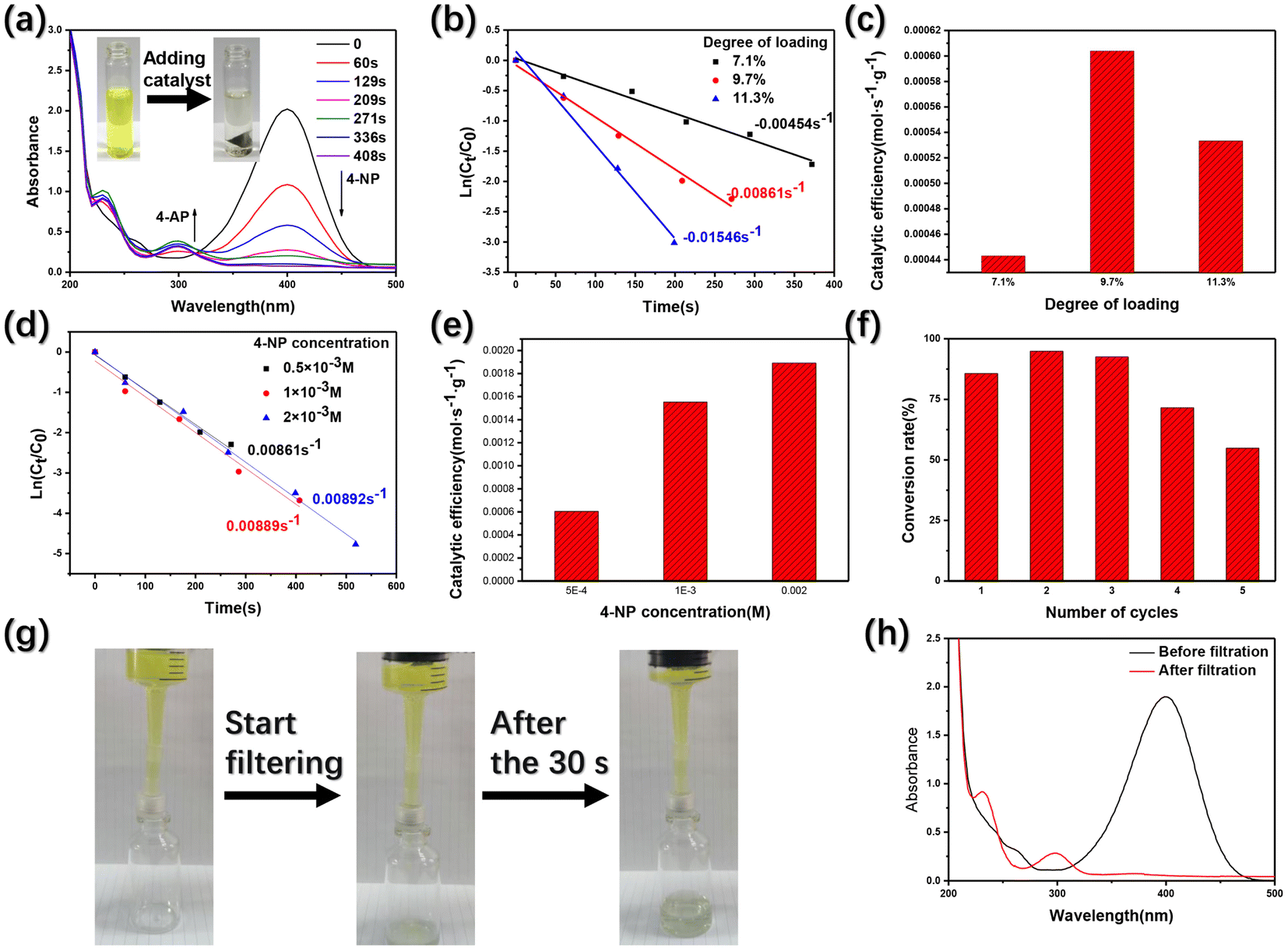 | ||
| Fig. 4 (a) Ultraviolet visible spectrum of 4-NP reduced to 4-AP by NaBH4 in the present of AgNCs@CF-g-PAA; (b) pseudo-first-order plot of catalytic process under different degree of loading; (c) catalytic efficiency of AgNCs@CF-g-PAA under different degree of loading; (d) pseudo-first-order plot of catalytic process under different 4-NP concentration; (e) catalytic efficiency of AgNCs@CF-g-PAA under different 4-NP concentration; (f) cyclic catalytic performance of AgNCs@CF-g-PAA; (g) diagram of filtration catalytic process; (h) ultraviolet visible spectrum before and after filtration. | ||
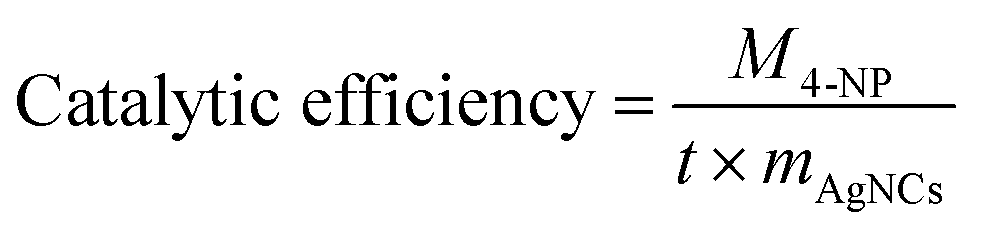
Further investigation of the catalytic behavior of AgNCs@CF-g-PAA shows that the catalytic rate of AgnCs@CF-g-PAA increases gradually with the increase of degree of loading of AgNCs@CF-g-PAA. Subsequently, AgNCs@CF-g-PAA catalytic efficiency at different degree of loading was calculated using the following eqn (4):
 | (4) |
The filter filled with AgNCs@CF-g-PAA was designed to briefly evaluate the actual catalytic behavior of AgNCs@CF-g-PAA. The overall device is shown in the figure (Fig. S8†), AgNCs@CF-g-PAA filled into the inner space of the filter. 4-NP solution mixed with sodium borohydride is then run slowly through a catalyst filled filter using a syringe. As shown in the figure (Fig. 4(g)), the solution is yellow before flowing through the catalytic filter. After passing through the catalytic filter, the color of the solution obviously lightened to colorless. The detailed filtration catalytic process is shown in movie S2.† Before flowing through the filter, the solution has a distinct absorption peak at 400 nm (Fig. 4(h)), which belongs to 4-NP. After passing through the filter, the absorption peak of 4-NP in the solution disappeared, and the absorption peak of 4-AP appeared at 300 nm. This shows that the filter filled with AgNCs@CF-g-PAA can achieve the catalysis of 4-NP in one filter, showing good practical application value. At the same time, AgNCs@CF-g-PAA can also be used in combination with filter paper and other filter devices to achieve the catalytic treatment of small molecular pollutants 4-NP that can not be separated from filter paper.
3.3 Hydrogen production performance of AgNCs@CF-g-PAA
It can be seen from the catalytic test that AgNCs has strong catalytic activity due to its small particle size. Based on this, AgNCs@CF-g-PAA may also be able to achieve efficient catalytic hydrolysis of sodium borohydride for hydrogen production. The specific hydrogen production device is shown in the Fig. 5(c), and the volume of hydrogen is calculated by drainage method. This is shown in the figure (Fig. 5(a)). The natural rate of hydrolysis of sodium borohydride is very slow. After adding AgNCs@CF-g-PAA catalyst, the hydrogen production rate of the system reached 10 times that of natural hydrolysis, showing good catalytic hydrogen production characteristics. The detailed hydrogen production process can be seen in the movie S3.† Moreover, AgNCs@CF-g-PAA exhibits a very fast hydrogen production rate at the time of addition (Fig. 5(a)). With the hydrolysis of sodium borohydride, the concentration of sodium borohydride in the system decreased gradually, resulting in a slow hydrogen production rate. For this reason, catalytic hydrogen production was tested at a higher concentration of sodium borohydride. As shown in the figure (Fig. 5(b)), AgNCs@CF-g-PAA can achieve higher rates of catalytic hydrogen production at higher concentrations of sodium borohydride. The hydrogen production rate of AgNCs@CF-g-PAA is calculated by the following eqn (5):
 | (5) |
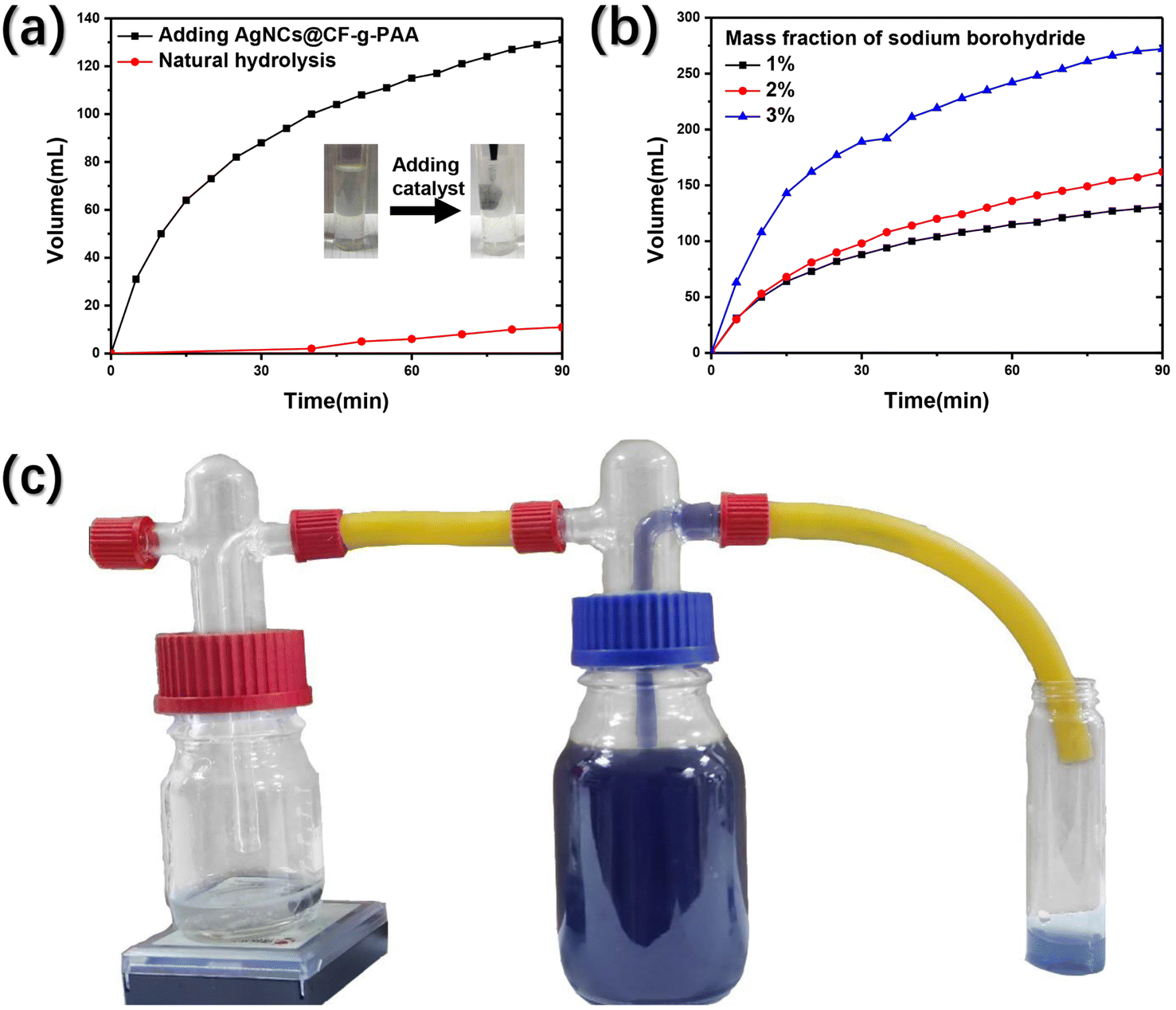 | ||
| Fig. 5 (a) Hydrogen volume over time; (b) hydrogen volume over time under mass fraction of sodium borohydride; (c) diagram of catalytic hydrogen production process. | ||
4 Conclusion
Here, a cheap catalytic material is prepared using radiation technology. Firstly, a solid template (CF-g-PAA) was obtained by radiation grafting of polyacrylic acid molecular chains on cotton fiber (CF). Then, silver nanoclusters (AgNCs) were loaded in situ on CF-g-PAA by radiation reduction, and the silver nanocluster-supported composite catalyst (AgNCs@CF-g-PAA) was obtained. AgNCs are fixed on AgNCs@CF-g-PAA and distributed evenly by the interaction between the carboxyl on the PAA molecular chain and AgNCs. Because of the simple synthesis condition of radiation technology, the degree of loading of AgNCs can be controlled simply. Using the high catalytic activity of small size AgNCs, AgNCs@CF-g-PAA can achieve efficient catalysis of water pollutant 4-nitrophenol (4-NP). Moreover, the material can be combined with the filter device, which has certain practical value. At the same time, AgNCs@CF-g-PAA can also realize the efficient catalytic hydrolysis of sodium borohydride, and make a certain contribution to hydrogen production. Due to the low cost of the base material and the simple synthesis route, this work provides an efficient and economical catalyst candidate for the treatment of water contaminants 4-NP and sodium borohydride hydrogen production.Data availability
Data will be made available on request.Conflicts of interest
The authors declare that they have no known competing financial interests or personal relationships that could have appeared to influence the work reported in this paper.Acknowledgements
This work was supported financially by the Gansu Natural Science Foundation (Project no. 20JR10RA778 and no. 20JR10RA777).References
- X. L. Qu, J. Brame, Q. L. Li and P. J. J. Alvarez, Acc. Chem. Res., 2013, 46, 834–843 CrossRef CAS PubMed.
- H. Lotze-Campen, C. Müller, A. Bondeau, S. Rost, A. Popp and W. Lucht, Agric. Econ., 2008, 39, 325–338 Search PubMed.
- H. W. Liang, X. Cao, W. J. Zhang, H. T. Lin, F. Zhou, L. F. Chen and S. H. Yu, Adv. Funct. Mater., 2011, 21, 3851–3858 CrossRef CAS.
- J. N. Halder and M. N. Islam, J. Environ. Pollut. Hum. Health, 2015, 2, 36–46 Search PubMed.
- S. J. Kim, S. H. Ko, K. H. Kang and J. Han, Nat. Nanotechnol., 2010, 5, 297–301 CrossRef CAS PubMed.
- J. G. Speight, in Natural Water Remediation, ed. J. G. Speight, Butterworth-Heinemann, 2020, pp. 165–198, DOI:10.1016/B978-0-12-803810-9.00005-X.
- J. J. Song, Z. F. Huang, L. Pan, K. Li, X. W. Zhang, L. Wang and J. J. Zou, Appl. Catal., B, 2018, 227, 386–408 CrossRef CAS.
- G. Eichenbaum, M. Johnson, D. Kirkland, P. O'Neill, S. Stellar, J. Bielawne, R. DeWire, D. Areia, S. Bryant, S. Weiner, D. Desai-Krieger, P. Guzzie-Peck, D. C. Evans and A. Tonelli, Regul. Toxicol. Pharmacol., 2009, 55, 33–42 CrossRef CAS PubMed.
- M. R. de Barros, O. R. Bittencourt, P. Z. Crocomo, G. Mafra, E. Carasek, H. A. Magosso, C. L. Jost and J. P. Winiarski, J. Sol-Gel Sci. Technol., 2021, 99, 402–412 CrossRef CAS.
- G. Varank, A. Demir, K. Yetilmezsoy, S. Top, E. Sekman and M. S. Bilgili, 2012.
- S. Gonzalez-Moran, B. Gonzalez, M. A. Vicente, R. Trujillano, V. Rives, A. Gil and S. A. Korili, Environ. Technol., 2022, 43, 402–410 CrossRef CAS PubMed.
- N. K. Vishwakarma and S. K. Mahto, Chem. Eng. J., 2023, 452, 10 CrossRef.
- A. I. Ayad, D. Luart, A. O. Dris and E. Guenin, Nanomaterials, 2020, 10, 16 Search PubMed.
- Z. Gao, R. X. Su, R. L. Huang, W. Qi and Z. M. He, Nanoscale Res. Lett., 2014, 9, 8 CrossRef PubMed.
- R. K. Dhokale, H. M. Yadav, S. N. Achary and S. D. Delekar, Appl. Surf. Sci., 2014, 303, 168–174 CrossRef CAS.
- A. A. L. Ahmad, S. Panicker, M. M. Chehimi, M. Monge, J. M. Lopez-de-Luzuriaga, A. A. Mohamed, A. E. Bruce and M. R. M. Bruce, Catal. Sci. Technol., 2019, 9, 6059–6071 RSC.
- J. Yang and R. C. Jin, ACS Mater. Lett., 2019, 1, 482–489 CrossRef CAS.
- R. J. Isaifan, S. Ntais and E. A. Baranova, Appl. Catal., A, 2013, 464, 87–94 CrossRef.
- L. Shang, S. J. Dong and G. U. Nienhaus, Nano Today, 2011, 6, 401–418 CrossRef CAS.
- H. X. Xu and K. S. Suslick, ACS Nano, 2010, 4, 3209–3214 CrossRef CAS PubMed.
- J. J. Wang, S. Y. Ma, J. C. Ren, J. X. Yang, Y. Qu, D. R. Ding, M. Zhang and G. Yang, Sens. Actuators, B, 2018, 267, 342–350 CrossRef CAS.
- Q. Qiu, R. R. Gao, A. M. Xie, Y. Z. Jiao and W. Dong, J. Photochem. Photobiol., A, 2020, 400, 7 CrossRef.
- F. Ali, S. B. Khan, T. Kamal, K. A. Alamry, A. M. Asiri and T. R. A. Sobahi, Sci. Rep., 2017, 7, 16957 CrossRef PubMed.
- M. H. Lee, K. J. Yoon and S. W. Ko, J. Appl. Polym. Sci., 2000, 78, 1986–1991 CrossRef CAS.
- S. Zhang, H. Dong, R. He, N. Wang, Q. Zhao, L. Yang, Z. Qu, L. Sun, S. Chen and J. Ma, Int. J. Biol. Macromol., 2022, 207, 100–109 CrossRef CAS PubMed.
- F. Ali, S. B. Khan and A. M. Asiri, Int. J. Hydrogen Energy, 2019, 44, 4143–4155 CrossRef CAS.
- H. Oraby, M. M. Senna, M. Elsayed and M. Gobara, J. Appl. Polym. Sci., 2017, 134, 11 CrossRef.
- G. Przybytniak, E. M. Kornacka, K. Mirkowski, M. Walo and Z. Zimek, Nukleonika, 2008, 53, 89–95 CAS.
- Q. Gao, J. Hu, R. Li, L. Pang, Z. Xing, L. Xu, M. Wang, X. Guo and G. Wu, Carbohydr. Polym., 2016, 149, 308–316 CrossRef CAS PubMed.
- H. H. Sokker, S. M. Badawy, E. M. Zayed, F. A. Nour Eldien and A. M. Farag, J. Hazard. Mater., 2009, 168, 137–144 CrossRef CAS PubMed.
- Rahmawati M. Suhartini and E. Budianto, Green preparation of silver nanocluster composite AgNCs@CF-g-PAA and its application: 4-NP catalytic reduction and hydrogen production, Yogyakarta, Indonesia, 2013.
- F. Han, J. Li, W. Wang, M. Wang and L. Li, RSC Adv., 2022, 12, 33207–33214 RSC.
- S. Zhang, L. Xu, J. Wu, Y. Yang, C. Zhang, H. Tao, J. Lin, L. Huang, W. Fang, K. Shi and X. Dong, Nano Res., 2022, 15, 1672–1679 CrossRef CAS.
- M. Yuan, Z. Cui, J. Yang, X. Cui, M. Tian, D. Xu, J. Ma and Z. Dong, Int. J. Hydrogen Energy, 2017, 42, 29244–29253 CrossRef CAS.
- R. D. Cortright, R. R. Davda and J. A. Dumesic, Nature, 2002, 418, 964–967 CrossRef CAS PubMed.
- L. Xu, S. Zhang, L. Huang, Y. Yang, H. Tao, J. Zhu, C. Yang, S. Li, R. Jin and X. Dong, Surf. Interfaces, 2022, 32, 102173 CrossRef CAS.
- J. Zhu, L. Xu, S. Zhang, Y. Yang, L. Huang, X. Zhang, T. Wang, X. Wang and X. Dong, New J. Chem., 2022, 46, 1821–1828 RSC.
- J. Jiang, J. Zhu, L. Wang, Y. Yang, T. Wang, T. Wang and X. Dong, Mater. Lett., 2022, 325, 132790 CrossRef CAS.
- X. Miao, M. M. Chen, W. Chu, P. Wu and D. G. Tong, ACS Appl. Mater. Interfaces, 2016, 8, 25268–25278 CrossRef CAS PubMed.
- W. Lv, L. Xu, L. Wang, Y. Yang, L. Wang, T. Wang, D. Li, H. Shao, F. Li and X. Dong, J. Alloys Compd., 2022, 920, 165934 CrossRef CAS.
- J. Zhu, W. Lv, Y. Yang, L. Huang, W. Yu, X. Wang, Q. Han and X. Dong, New J. Chem., 2022, 46, 10280–10288 RSC.
- V. G. Minkina, V. I. Kalinin and S. I. Shabunya, Theor. Found. Chem. Eng., 2016, 50, 536–541 CrossRef CAS.
- H. N. Abdelhamid, Int. J. Hydrogen Energy, 2021, 46, 726–765 CrossRef CAS.
- L. Shang and S. J. Dong, Chem. Commun., 2008, 1088–1090, 10.1039/b717728c.
- F. C. Moraes, S. T. Tanimoto, G. R. Salazar-Banda, S. A. S. Machado and L. H. Mascaro, Electroanalysis, 2009, 21, 1091–1098 CrossRef CAS.
- N. Wang, F. Wang, F. Pan, S. Yu and D. Pan, ACS Appl. Mater. Interfaces, 2021, 13, 3209–3220 CrossRef CAS PubMed.
- Z. Q. Xu, X. H. He, M. W. Liang, L. J. Sun, D. Li, K. A. Xie and L. Liao, Mater. Chem. Phys., 2019, 227, 64–71 CrossRef CAS.
- A. F. Baye, R. Appiah-Ntiamoah and H. Kim, Sci. Total Environ., 2020, 712, 12 CrossRef PubMed.
- W. Zhou, Y. Fang, J. Ren and S. Dong, Chem. Commun., 2019, 55, 373–376 RSC.
- J. N. Solanki and Z. V. P. Murthy, Ind. Eng. Chem. Res., 2011, 50, 7338–7344 CrossRef CAS.
- J. Lü, Y. Fu, Y. Song, D. Wang and C. Lü, RSC Adv., 2016, 6, 14247–14252 RSC.
- S. Hao, S. Li and Z. Jia, J. Nanopart. Res., 2020, 22 Search PubMed.
- A. M. Garcia, T. S. Martins and F. F. Camilo, Cellulose, 2021, 28, 4899–4911 CrossRef CAS.
- X. Fang, J. Li, B. Ren, Y. Huang, D. Wang, Z. Liao, Q. Li, L. Wang and D. D. Dionysiou, J. Membr. Sci., 2019, 579, 190–198 CrossRef CAS.
- Q. Zhang, R. J. Somerville, L. Chen, Y. Yu, Z. Fei, S. Wang, P. J. Dyson and D. Min, J. Hazard. Mater., 2023, 443, 130270 CrossRef CAS PubMed.
- X. Li, F. Dong, L. Zhang, Q. Xu, X. Zhu, S. Liang, L. Hu and H. Xie, Chem. Eng. J., 2019, 372, 516–525 CrossRef CAS.
- W. Ye, H. Zhang, D. Xu, L. Ma and B. Yi, J. Power Sources, 2007, 164, 544–548 CrossRef CAS.
- H. Cai, L. Liu, Q. Chen, P. Lu and J. Dong, Energy, 2016, 99, 129–135 CrossRef CAS.
- Z.-M. Huang, A. Su and Y.-C. Liu, Int. J. Energy Res., 2013, 37, 1187–1195 CrossRef CAS.
- H.-C. Kang, Y. Chen, E. E. Arthur and H. Kim, Int. J. Hydrogen Energy, 2014, 39, 15656–15664 CrossRef CAS.
- N. Malvadkar, S. Park, M. Urquidi-MacDonald, H. Wang and M. C. Demirel, J. Power Sources, 2008, 182, 323–328 CrossRef CAS.
Footnote |
| † Electronic supplementary information (ESI) available. See DOI: https://doi.org/10.1039/d3ra01245j |
| This journal is © The Royal Society of Chemistry 2023 |