 Open Access Article
Bandgap modification in 0D tellurium iodide perovskite derivatives via incorporation of polyiodide species†
Benjamin W. Walusiak ,
Adharsh Raghavan and
Christopher L. Cahill
 *
*
Department of Chemistry, The George Washington University, 800 22nd Street, NW, Washington D.C. 20052, USA. E-mail: cahill@gwu.edu
First published on 3rd May 2023
Abstract
Halide perovskites provide a versatile platform for exploring the effect of non-covalent interactions, including halogen bonding, on material properties such as band gap, luminescence, and frontier orbital landscape. Herein we report six new zero-dimensional tellurium iodide perovskite derivatives, consisting of [TeI6]2− octahedra charge balanced by one of several X-Py cations (X = H, Cl, Br, I, and Py = pyridinium). These compounds also feature robust halogen bonding between [TeI6]2− octahedra and polyiodides in the form of I2 (1–4), I3− (5), or adjacent octahedra (4 and 6). These relatively strong non-covalent interactions (NCIs) are modeled by natural bond order (NBO) and second order perturbation theory (SOPT) calculations. NCIs are responsible for reducing the bandgap of these materials (measured via diffuse reflectance spectroscopy) relative to those without polyiodide species. They also affect inner sphere bonding in the metal halide, exacerbating [TeI6]2− octahedron asymmetry as compared to previously published compounds, with greater asymmetry correlating with higher van der Waals overlap of halogen–halogen contacts. We also demonstrate the ability of hydrogen and carbon bonding (which dominates in the absence of polyiodides) to affect inner sphere tellurium iodide bonding and octahedral symmetry.
Introduction
Halide perovskites and their derivatives are a class of structurally and functionally diverse materials with relevance to photovoltaics, semiconductors, and radiation detection.1–3 Our group and others have explicitly shown the potential of non-covalent interactions (NCIs) to influence crystal formation, stability, and material properties (e.g. band gap) of perovskites or perovskite derivatives.4,5 Halogen bonding in particular has also been utilized to improve the stability, quality, and overall efficiency of halide perovskite photovoltaics,6 and systematic interrogation of new compositions and structural motifs will serve to advance understanding in these areas. Zero-dimensional (0D) halide perovskite derivatives, consisting of entirely discrete metal halide octahedra separated by cations (both organic and inorganic) are increasingly relevant to the applications mentioned above.7–9 These 0D materials provide a similar platform for tunability of optoelectronic properties, among others, with the tendency toward greater environmental stability, than their three-dimensional counterparts.10,11 0D perovskite derivatives are attractive for use as solar materials, and scintillators in particular, which require a high degree of stability while retaining desirable photophysical properties.6–8 Pb, Sn, Bi, Sb e.g. are all frequently explored as components of low dimensional perovskites with properties appropriate for these applications. Tellurium has been probed less extensively than other metals, though it may also form low dimensional compounds with similar characteristics. Te has also been utilized as a dopant in perovskite materials, acting as an emission center in Sn chloride scintillators under X-ray irradiation e.g. ref. 12.Distortion of the metal halide coordination geometry has been shown to be an important factor in determining properties of halide perovskites such as band gap.13 The identity of the organic cation, halogen on the metal halide, and doping have all been employed to influence the degree of distortion in metal halide octahedra, and subsequently tune their material properties.13,14 Metal halides with ns2 lone pairs (Te included, 5s2) have also demonstrated distortion in the excited state, which has in turn been tied to their relatively broad emission, via the formation of self-trapped excitons (STEs).15 Since these 0D materials consist of discrete components assembled entirely via NCIs, there is significant motivation to characterize these types of interactions in 0D perovskite derivatives. Careful investigation of NCIs such as hydrogen or halogen bonding is essential for establishing relationships between material properties and the non-covalent forces at play in these materials.
Halogen bonding and its influence on material properties
Halogen bonding may be defined as an attractive non-covalent interaction indicated structurally by the interpenetration of the van der Waals volumes of two halogen atoms (usually expressed as a % of the sum of the vdW radii).16 This phenomenon can arise due to the polarization of a halogen atom covalently bound to another atom, carbon for example, enabling the halogen to act as an electron acceptor.17 Computational studies have shown that charge transfer from a halogen bond donor to an acceptor can result in a significant stabilization energy between the two species, in addition to the electrostatic interactions arising from polarization of the halogen.18 Our group has explored the role of NCIs in Te, In, and Sb 0D perovskite derivatives, where we thoroughly characterize these interactions to evaluate their impact on overall structure and material properties.4,19 These works have demonstrated that second sphere NCIs can substantively affect material properties as well as influence the inner sphere characteristics of the metal halide.This present effort began as a direct extension of our previous work on Te chlorides and bromides, yet new and unique structural motifs and NCIs presented themselves in this tellurium iodide system. We present a series of new [TeI6]2− based halide perovskite derivatives paired with halogenated pyridinium cations, and all except for one of these new structures contains polyiodide species, in the form of I2 or I3−. Although this type of polyiodide-containing compound is often reported as an impurity or side product,20 we take the opportunity here to investigate the significant effect of polyiodides on crystal structure and material properties. These materials feature robust non-covalent interactions (NCIs), including halogen bonding between the polyiodide species and the metal halide, which contribute to the asymmetry of the [TeI6]2− octahedra. A combination of crystallographic and computational analyses, including natural bond orbitals (NBO), density of states (DOS), and electrostatic potential (ESP) surfaces, allows a comprehensive characterization of the effects of polyiodides on crystal structure and material properties within this series of compounds. The presence of polyiodides substantively affects the band gap of our materials, lowering it in comparison to those without polyiodide species.
Experimental
Reagents were purchased from the following vendors and used as received. Tellurium oxide (TeO2): Alfa Aesar, hydroiodic acid: BTC chemical, pyridine, 4-chloropyridine hydrochloride, 4-bromopyridine hydrochloride, 4-iodopyridine, pyrazine: Sigma Aldrich.General synthesis of [1–10]
These efforts represent exploratory, relatively unoptimized syntheses. Herein we rely on in situ generation of polyiodides by oxidation of iodide to molecular iodine, which can then combine with additional iodide to form I3−.21 As such, all reactions were performed in air and utilized stabilized hydroiodic acid as the I− source. Hydrothermal synthesis was employed to aid in the incorporation of I2 specifically and resulted in the formation of 1–3. Compounds 4–7 were produced using slow evaporation, rather than hydrothermal methods, and so showed a range of polyiodide incorporation.X-ray crystallography
Crystals of 1–10 were harvested from dried products or filtered solids and mounted on MiTeGen micromounts. All measurements were made using monochromated microfocus Mo Kα (λ = 0.71073 Å) radiation on a Bruker D8 Quest, equipped with a Photon II detector. All reflections were collected at 100(2) K with 0.5° φ and ω scans. Initial space group determination was performed using a single φ scan in the APEX III software suite. The data were reduced using SAINT23 and empirical absorption correction applied using SADABS.24 Structures solutions, solved using intrinsic phasing, and refinement were performed using the ShelXT package25 and ShelXL26 in APEX III. ShelXle,26 OLEX 2,27 and PLATON28 programs were used for subsequent refinement, modeling of disorder, and space group changes when necessary. All atoms were refined anisotropically, and aromatic hydrogen atoms were placed in idealized positions using the appropriate AFIX command and allowed to ride on the coordinates of the parent atom with isotropic thermal parameters (Uiso) fixed at 1.2 Ueq. Specific crystal structure parameters of 1–10 are summarized in Table 1. CheckCIF documents containing thermal ellipsoids (generated via ORTEP29) for 1–10 can be found in the ESI.†| 1 | 2 | 3 | 4 | 5 | |
|---|---|---|---|---|---|
| CCDC no. | 2238872 | 2238873 | 2238874 | 2238875 | 2238876 |
| Formula | (C5H5NH)2[TeI6]·I2 | (C5H5NCl)2[TeI6]·I2 | (C5H5NI)2[TeI6]·I2 | (C4H6N2)2[TeI6]·2(I2) | (C5H5NCl)3[TeI6]·I3 |
| Crystal system | Monoclinic | Monoclinic | Trigonal | Triclinic | Triclinic |
| Space group | C2/c | Cc | P32 | P![[1 with combining macron]](https://www.rsc.org/images/entities/char_0031_0304.gif) |
P![[1 with combining macron]](https://www.rsc.org/images/entities/char_0031_0304.gif) |
| a (Å) | 18.0503(11) | 19.0162(14) | 15.0194(10) | 9.4074(3) | 8.9408(3) |
| b (Å) | 10.1185(6) | 10.6017(8) | 15.0194(10) | 11.5528(4) | 9.9568(4) |
| c (Å) | 14.6269(8) | 14.2508(11) | 33.038(3) | 13.8021(4) | 19.7612(8) |
| α (°) | 90 | 90 | 90 | 81.7110(10) | 103.0060(10) |
| β (°) | 106.830(2) | 111.154(3) | 90 | 79.8470(10) | 96.6570(10) |
| γ (°) | 90 | 990 | 120 | 69.0100(10) | 90.2810(10) |
| Volume (Å3) | 2557.06 | 2679.42 | 6454.31 | 1373.2 | 1701.62 |
| Z | 4 | 2 | 3 | 4 | 4 |
| ρcalc (g cm−3) | 3.385 | 3.401 | 3.6 | 3.77 | 3.149 |
| Radiation | 0.71073 | 0.71073 | 0.71073 | 0.71073 | 0.71073 |
| Temp. (K) | 100 | 100(2) | 100(2) | 100(2) | 100(2) |
| Residuals: R (Rint) | 0.0305, 0.0584 | 0.0348, 0.0601 | 0.0242, 0.0963 | 0.0200, 0.0426 | 0.0340, 0.0426 |
| 6 | 7 | 8 | 9 | 10 | |
|---|---|---|---|---|---|
| CCDC no. | 2238877 | 2238878 | 2238879 | 2238880 | 2238881 |
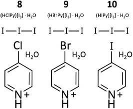
| Formula | (C5H5NBr)2[TeI6] | (HIPy)2[TeI6]·H2O | (HClPy)[I3]·H2O | (HBrPy)[I3]·H2O | (HIPy)[I3]·H2O |
| Crystal system | Monoclinic | Triclinic | Triclinic | Monoclinic | Monoclinic |
| Space group | P21/n | P![[1 with combining macron]](https://www.rsc.org/images/entities/char_0031_0304.gif) |
P![[1 with combining macron]](https://www.rsc.org/images/entities/char_0031_0304.gif) |
C2/c | C2/c |
| a (Å) | 12.1949(6) | 7.7588(4) | 7.0961(3) | 22.6882(7) | 22.8618(8) |
| b (Å) | 14.1651(7) | 11.8319(4) | 7.8772(3) | 7.0484(2) | 7.1336(2) |
| c (Å) | 14.3164(7) | 14.2751(8) | 11.4958(5) | 15.6003(5) | 15.7192(6) |
| α (°) | 90 | 86.842(2) | 95.461(2) | 90 | 90 |
| β (°) | 110.829(2) | 80.992(2) | 99.379(2) | 101.8650(10) | 103.2200(10) |
| γ (°) | 90 | 78.3800(10) | 107.782(2) | 90 | 90 |
| Volume (Å3) | 2311.42 | 1267.41 | 592.48 | 2441.43 | 2495.66 |
| Z | 4 | 2 | 2 | 8 | 8 |
| ρcalc (g cm−3) | 3.469 | 3.456 | 2.858 | 3.3035 | 3.219 |
| Radiation | 0.71073 | 0.71073 | 0.71073 | 0.71073 | 0.71073 |
| Temp. (K) | 100(2) | 100(2) | 100(2) | 100(2) | 100(2) |
| Residuals: R (Rint) | 0.0208, 0.0765 | 0.0203, 0.0469 | 0.0264, 0.0600 | 0.0223, 0.0422 | 0.0167, 0.0422 |
A noticeable gap in our suite of materials is present in that the TeI6 + BrPy analogue containing I2 is not reported above. Like 1–3, hydrothermal syntheses (at 70 °C) involving tellurium and BrPy did yield single crystals, however these structures could not be adequately refined. In the P32 trigonal space group, 8 twin domains are possible simply due to the symmetry of the system.30 Despite the application of several simultaneous twin laws to try and resolve the merohedral twinning issue, a satisfactory refinement was not obtained. However, powder X-ray diffraction (PXRD, Fig. S12†) revealed the presence of a compound nearly identical to 3 in syntheses attempting to make (HBrPy)2[TeI6]·I2. It is therefore reasonable to surmise that the structure of (HBrPy)2[TeI6]·I2 is analogous to that of 3.
Photophysical measurements
Diffuse reflectance spectra were collected on solid, dry samples at 298 K. Spectra were collected from 200 nm to 1500 nm on a Jasco V-770 UV-visible/NIR spectrophotometer equipped with a 60 mm integrating sphere (Jasco ISN-923). Data were processed using Spectra Manager™ Suite spectroscopy software. Steady-state luminescence scans of 1–3 and 5 were collected at 298 K and 78 K with a Fluorologs-3 photoluminescence spectrophotometer from Horiba using a 450 W xenon arc lamp combined with a double excitation monochromator and double emission monochromator, with a photomultiplier tube at 950 V used as the emission detector. Low temperature luminescence measurements were collected on solid samples under vacuum using a Janis VPF-100 cryostat equipped with UV-grade fused silica windows coupled with a Lakeshore model 325 temperature controller.Computational methods
Natural bond orbital (NBO) analyses, including second order perturbation theory (SOPT) calculations, were performed using the NBO7 package as implemented in Gaussian 16, rev. C.01.31 The model chosen for NBO calculations consisted of a central [TeI6]2− species and its vdW or near-vdW contacts, including organic cations and other molecular species. The coordinates of all atoms were taken from the single crystal X-ray diffraction data for each compound. Single point energy (SPE) calculations were performed using the B3LYP32,33 functional and the def2-tzvp34,35 basis set for all atoms (with effective core potential (ECP) for I and Te).Density of states (DOS) and SPE calculations incorporating periodic boundary conditions (PBC) were performed using Gaussian 16, rev. C.01 on crystallographically determined unit cells, using the HSEh1PBE36 functional and the basis sets def2-tzvp for Cl, Br, I and Te (with ECP for I and Te), and 6-311G** (ref. 37 and 38) for C, H and N atoms. Total and partial density of states (TDOS, PDOS) data were extracted using Multiwfin v3.7.39 Individual PDOS fragments were generated using appropriate atomic orbital contributions (s and p orbitals of Te, I, Cl and Br atoms, and p orbitals of C and N atoms). DOS curves were plotted at a FWHM of ca. 0.25 eV.
Elemental analysis
Elemental analysis was performed on all compounds by Atlantic Microlab, Inc. for C, H, N, and I. Results are tabulated in Table S3.†Results and discussion
Structure descriptions
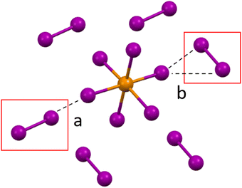 | ||
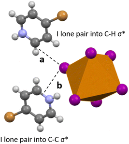
| Fig. 3 a. Halogen bonding in compounds 1–3 between the [TeI6]2− octahedron between end on (a) and side on (b) I2 molecules. | ||
Compound 1 (HPy)2[TeI6]·I2 has been reported previously by Faoro et al., during the investigation of aryltellurenyl iodides, although with slightly different crystallographic parameters, likely due to the difference in collection temperatures (293 K vs. 100 K).41 Compound 1 (Fig. 4) crystallizes in the C2/c space group, and the average Te–I bond length is 2.940(1) Å, with min. and max. I–Te–I angles of 87.5° and 92.4° respectively. As in all compounds presented here, 1 consists of [TeI6]2− octahedra charge-balanced by organic cations and features discrete I2 molecules halogen bonded with the [TeI6]2−. For brevity, we will describe the strongest halogen bonding interactions in each compound, which for 1–3 occur between end-on bound I2 molecules and the [TeI6]2−. For 1, a single crystallographically unique end-on I2 is present with a Te–I⋯I2 distance of 3.252(1) Å. This represents a significant overlap of the van der Waals (vdW) radii of the Te bound iodine and the I2 iodine, 82.1% of the sum of the vdW radii (hereafter expressed as % vdW).42 In contrast, halogen bonding distances between [TeI6]2− and side-on I2 are ∼98% vdW. More insight into the nature of this rather robust interaction is given in the computational results section. Hydrogen bonding also contributes to the overall assembly of 1–7, and is present in 1–3 between [HXPy]+ and [TeI6]2−.
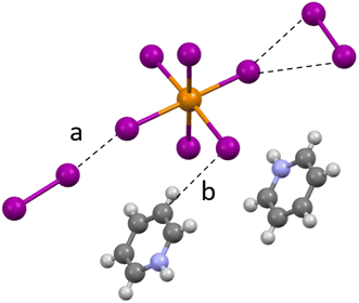 | ||
| Fig. 4 A portion of the structure of 1 showing (a) halogen bonding and (b) hydrogen bonding between I2 and pyridinium species. | ||
Compound 2 (HClPy)2[TeI6]·I2 (Fig. 5) exhibits a similar second sphere coordination environment as 1, crystallizing in the lower symmetry Cc space group. The average Te–I bond length is 2.947(1) Å, with min. and max. I–Te–I angles of 85.9° and 93.2° respectively. The closest halogen–halogen contacts are once again the two end-on coordinated I2 molecules with Te–I⋯I2 distances of 3.287(1) Å and 3.353(1) Å, 83.0% and 84.7% vdW respectively. The Cl substituent on the chloropyridinium is just beyond overlapping with the vdW radius of the tellurium bound iodine, with a Cl⋯I distance of 3.740(1) Å, or 100.3% vdW. Fig. 5 shows examples of each type of non-covalent interaction present.
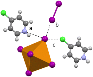 | ||
| Fig. 5 Second sphere interaction in 2. (a) Hydrogen bonding; (b) and (c) halogen bonding between the [TeI6]2− octahedron and an end-on I2 and ClPy respectively. | ||
Compound 3 (HXPy)2[TeI6]·I2 crystallizes in the P32 space group, a stark departure from monoclinic space groups of 1 and 2. Nevertheless the [TeI6]2− octahedra in 3 retain the same second sphere coordination as 1 and 2. The average Te–I bond length is 2.954(1) Å, with min. and max. I–Te–I angles of 85.41° and 93.59° respectively. Due to the symmetry of 3, there are 3 crystallographically unique [TeI6]2− octahedra (Fig. S15†), so an average of their closest (end on) Te–I⋯I2 coordination distances were taken for the purpose of comparison. These distances are 3.367(1) Å and 3.394(1) Å, 85.0% and 85.7% respectively. Iodine atoms on multiple iodopyridiniums were modelled as disordered, indicating a disorder of the entire pyridinium molecule.
Compound 4 (HPyz)2[TeI6]·I2 crystallizes in the P![[1 with combining macron]](https://www.rsc.org/images/entities/char_0031_0304.gif) space group and exhibits a completely different second sphere coordination from 1–3 (Fig. 6). In this new arrangement, there are still I2 molecules involved in halogen bonding with the [TeI6]2−, the shortest of which is 3.316(1) Å, 83.7% vdW. There is also halogen bonding present between the I atoms on adjacent [TeI6]2−, with the closest contact being 3.582(1) Å, 90.5% vdW. [TeI6]2− octahedra are charge balanced by infinite 1D chains of singly protonated pyrazine molecules hydrogen bonded to one another end to end, with additional hydrogen bonding to both I2 and [TeI6]2−. Like 1–3, the [TeI6]2− octahedron is slightly distorted, with an average Te–I bond length of 2.949(1) Å and min. max. I–Te–I angles of 86.48° and 95.88° respectively. This compound demonstrates the diversity of potential second sphere coordination environments around the [TeI6]2− while still retaining a large vdW overlap between the tellurium iodide and the I2. We wish to highlight the robust nature and variety of the [TeI6]2−⋯I2 halogen bonding in compounds 1–4 in general, while not discounting that hydrogen bonding also plays a role in the assembly of these compounds.
space group and exhibits a completely different second sphere coordination from 1–3 (Fig. 6). In this new arrangement, there are still I2 molecules involved in halogen bonding with the [TeI6]2−, the shortest of which is 3.316(1) Å, 83.7% vdW. There is also halogen bonding present between the I atoms on adjacent [TeI6]2−, with the closest contact being 3.582(1) Å, 90.5% vdW. [TeI6]2− octahedra are charge balanced by infinite 1D chains of singly protonated pyrazine molecules hydrogen bonded to one another end to end, with additional hydrogen bonding to both I2 and [TeI6]2−. Like 1–3, the [TeI6]2− octahedron is slightly distorted, with an average Te–I bond length of 2.949(1) Å and min. max. I–Te–I angles of 86.48° and 95.88° respectively. This compound demonstrates the diversity of potential second sphere coordination environments around the [TeI6]2− while still retaining a large vdW overlap between the tellurium iodide and the I2. We wish to highlight the robust nature and variety of the [TeI6]2−⋯I2 halogen bonding in compounds 1–4 in general, while not discounting that hydrogen bonding also plays a role in the assembly of these compounds.
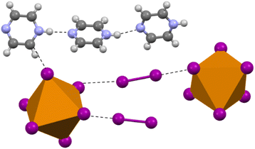 | ||
| Fig. 6 Selection from the structure of 4 showing the overall coordination environment, both halogen and hydrogen bonding, in contrast to compounds 1–3. | ||
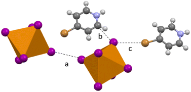
Compound 5 (HClPy)3[TeI6(I3)] crystallizes in the P![[1 with combining macron]](https://www.rsc.org/images/entities/char_0031_0304.gif) space group and modification of synthesis parameters results in the inclusion of I3− rather than I2. Analogous to 1–4, halogen bonding occurs between the I3− species and the [TeI6]2− in both side-on and end-on arrangements (Fig. 7). A somewhat smaller degree of van der Waals overlap occurs between I3− and [TeI6]2−, compared to the larger overlap present in the end-on I2 interactions in 1–3. Relevant distances and angles for the end on halogen interaction (Te–I⋯I3−) in 5 are: 3.630(1) Å, 91.67% vdW. Side-on I3− interactions have a lesser vdW overlap of ∼97%, again analogous to 1–3. The average Te–I bond length is 2.937(1) Å and min. and max. I–Te–I angles of 87.17° and 91.86° respectively.
space group and modification of synthesis parameters results in the inclusion of I3− rather than I2. Analogous to 1–4, halogen bonding occurs between the I3− species and the [TeI6]2− in both side-on and end-on arrangements (Fig. 7). A somewhat smaller degree of van der Waals overlap occurs between I3− and [TeI6]2−, compared to the larger overlap present in the end-on I2 interactions in 1–3. Relevant distances and angles for the end on halogen interaction (Te–I⋯I3−) in 5 are: 3.630(1) Å, 91.67% vdW. Side-on I3− interactions have a lesser vdW overlap of ∼97%, again analogous to 1–3. The average Te–I bond length is 2.937(1) Å and min. and max. I–Te–I angles of 87.17° and 91.86° respectively.
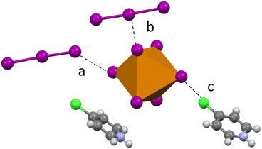 | ||
| Fig. 7 Examples of second sphere interactions in 5: halogen bonding between the [TeI6]2− and an (a) end-on I3, (b) side-on I3, and (c) chlorine substituent on the pyridinium. | ||
I3− containing crystal structures are sometimes reported as side products in the literature, with an example being (dimethylammonium)3[PtI6(I3)] by Evans et al.20 a study focused on mainly compunds containg I2. A search of the Cambridge Structural Database (CSD) reveals only a single (divalent) tellurium halide containing I3− ((C3H10N)2[Te(2+)I4]) and no structures combining Te(4+) and I3−. Compound 5 therefore represents a rarely reported structural motif for Te halide based materials. As with I3−, many authors seem to first encounter I2 containing materials pursing other products, as reported by Faoro et al.41 This precedent should not diminish the importance of polyiodides, as the presence of I2 has been demonstrated to play a role in the defect chemistry of the well-known halide perovskite MAPbI3, as well as in the degradation pathway of Sn based perovskite solar cells.41,43,44 Additionally, polyhalide rich solutions have recently been utilized as a crystallization aid in halide perovskite based solar cells.45 The presence of discrete I2 molecules has also been reported before in Pt halides, yet this study emphasized hydrogen bonding between I2 and the organic cations, referencing halogen bonding only in passing.20 In our case, the organic molecules do not seem to systematically complement or template the positions of I2 in the crystal. We instead call attention to the robust I2⋯[TeI6]2− halogen bonds present in 1–5. Novikov et al. focused on the properties of photovoltaic devices made with polyiodide containing materials, while noting the role of halogen bonding between I2 and [TeBr6]2− in assembling their materials. Considering these observations, we see an opportunity to advance our understanding of the halogen bonding interactions between the I2 and metal halide. Compounds 1–6 provide a platform to systematically probe the effects of polyiodides and halogen bonding on structure and material properties.
Compound 6 (HBrPy)2[TeI6] crystallizes in the P21/n space group and contains no polyiodide species owing to changes in synthesis detailed in the experimental section. As in 2–5 there is halogen bonding between the BrPy and the [TeI6]2−, with a Br⋯I distance of 3.758(1) Å (98.12% vdW). There is also halogen bonding between adjacent [TeI6]2− units, with the shortest Te–I⋯I–Te distance being 3.801(1) Å (96.0% vdW). (Fig. 8). The average Te–I bond length is 2.944(1) Å with min. and max. I–Te–I angles of 86.6° and 93.4° respectively. In addition, compound 6 exhibits carbon bonding,46 where the interaction is between the halogen donor and C![[double bond, length as m-dash]](https://www.rsc.org/images/entities/char_e001.gif) C or C
C or C![[double bond, length as m-dash]](https://www.rsc.org/images/entities/char_e001.gif) N σ* bonds in [HXpy]+, as opposed to the C–H or N–H bond σ*, is present along with normal hydrogen bonding. The Te–I⋯C distance (see Fig. 8b) is 3.489(1) Å additional details on this interaction can be found in the computational section.
N σ* bonds in [HXpy]+, as opposed to the C–H or N–H bond σ*, is present along with normal hydrogen bonding. The Te–I⋯C distance (see Fig. 8b) is 3.489(1) Å additional details on this interaction can be found in the computational section.
Compound 7 (IPy)2[TeI6]·H2O crystallizes in the P![[1 with combining macron]](https://www.rsc.org/images/entities/char_0031_0304.gif) space group and exhibits halogen bonding with the IPy is present (Fig. S18†), with the later having an I⋯I distance of 3.836 (1) Å (96.9% vdW). There is also halogen bonding between adjacent [TeI6]2− units, with the shortest Te–I⋯I–Te distance being 3.830(1) Å (96.7% vdW). Unlike 1–5, 7 does not contain polyiodides, but rather an H2O molecule, highlighting the possible diversity of the tellurium iodide – pyridinium system. Due to its low yield during synthesis 7 is excluded from most subsequent analyses.
space group and exhibits halogen bonding with the IPy is present (Fig. S18†), with the later having an I⋯I distance of 3.836 (1) Å (96.9% vdW). There is also halogen bonding between adjacent [TeI6]2− units, with the shortest Te–I⋯I–Te distance being 3.830(1) Å (96.7% vdW). Unlike 1–5, 7 does not contain polyiodides, but rather an H2O molecule, highlighting the possible diversity of the tellurium iodide – pyridinium system. Due to its low yield during synthesis 7 is excluded from most subsequent analyses.
Compiled crystallographic metrics
![[1 with combining macron]](https://www.rsc.org/images/entities/char_0031_0304.gif) ) and ((C19H18P)2[TeI6] space group C2/c), which have Δd values of 1.68 × 10⁻⁴ and 1.58 × 10⁻⁶ respectively.52,53 In these hybrid organic–inorganic compounds, only hydrogen bonding between the organic components and the metal halide is present. Numerical values for our compounds range from as low as ∼10−6 (for previously reported [TeCl6]2− and [TeBr6]2− based compounds) to as high as ∼10−3 in compounds 1–6 reported here (Table 2). 1–6 have a much larger distortion metric than any [TeI6]2− containing compound present in the CSD, and also larger than our previously reported [TeCl6]2− and [TeBr6]2− based materials. The distortion metric in 1–6 tends to increase as the halogen bond between [TeI6]2− and end-on I2 species becomes shorter (lower % in Table 2). These data suggest that halogen bonding may increase distortion of the metal halide octahedron, beyond what has been observed to arise due to an asymmetric packing environment and hydrogen bonding with [TeI6]2−. We therefore call attention to the potential utility of this polyiodide halogen bonding motif to affect the distortion of metal halides. Additional metrics involving octahedral distortion can be seen in subsequent sections.
) and ((C19H18P)2[TeI6] space group C2/c), which have Δd values of 1.68 × 10⁻⁴ and 1.58 × 10⁻⁶ respectively.52,53 In these hybrid organic–inorganic compounds, only hydrogen bonding between the organic components and the metal halide is present. Numerical values for our compounds range from as low as ∼10−6 (for previously reported [TeCl6]2− and [TeBr6]2− based compounds) to as high as ∼10−3 in compounds 1–6 reported here (Table 2). 1–6 have a much larger distortion metric than any [TeI6]2− containing compound present in the CSD, and also larger than our previously reported [TeCl6]2− and [TeBr6]2− based materials. The distortion metric in 1–6 tends to increase as the halogen bond between [TeI6]2− and end-on I2 species becomes shorter (lower % in Table 2). These data suggest that halogen bonding may increase distortion of the metal halide octahedron, beyond what has been observed to arise due to an asymmetric packing environment and hydrogen bonding with [TeI6]2−. We therefore call attention to the potential utility of this polyiodide halogen bonding motif to affect the distortion of metal halides. Additional metrics involving octahedral distortion can be seen in subsequent sections.
 , where dm is a metal-halogen distance and dave is the average M–X distance
| Compound | Chemical formula | Closest halogen vdW overlap % | Distortion metric (Δd) |
|---|---|---|---|
| 1 | (HPy)2[TeI6]·I2 | 82.1 | 1.49 × 10⁻³ |
| 2 | (HClPy)2[TeI6]·I2 | 83.0 | 1.39 × 10⁻³ |
| 3 | (HIPy)2[TeI6]·I2 | 85.0 | 1.01 × 10⁻³ |
| 4 | (HPyz)2[TeI6]·I2 | 83.7 | 6.78 × 10⁻⁴ |
| 5 | (HClPy)3[TeI6]·I3 | 91.2 | 3.72 × 10⁻⁴ |
| 6 | (HBrPy)2[TeI6] | 98.1 | 6.54 × 10⁻⁴ |
| SOSYEG30 | (C22H20O2P)2[TeI6] | n/a | 1.68 × 10⁻⁴ |
| IRIHEW31 | (C19H18P)2[TeI6] | n/a | 1.58 × 10⁻⁶ |
| OMOLEK4 | (HIPy)2[TeCl6] | 92.6 | 4.61 × 10⁻⁶ |
| OMOMAH4 | (HIPy)2[TeBr6] | 92.2 | 3.45 × 10⁻⁶ |
Luminescence
Compounds 1–6 were not found to be luminescent at room temperature or at 77 K. All inorganic tellurium halides, e.g. Cs2TeX6 (X = Cl, Br, I) exhibit luminescence output with intensities varying as Cl > Br ≫ I.51,54 Our previous work with tellurium chloride and bromide halo pyridiniums found that their luminescence is only significant at low temperature (∼77 K), and is sometimes not present at all.4 The combined presence of pyridinium cations and polyiodides, especially considering the intimate second sphere contacts present in 1–5, likely provides multiple pathways for non-radiative decay of the excited [TeI6]2−. Besides eliminating polypodies, other organic cations besides pyridine could be potentially utilized in an attempt to improve luminescent behavior. Biswas et al. noted that benzyltriethylammonium, in contrast to various other organic cations, resulted in high room temperature photoluminescence quantum yield of a hybrid organic–inorganic tellurium chloride. Lack of luminescence does not preclude the possible use of these materials as potential direct radiation detectors or photovoltaic devices e.g., where electron hole pairs are detected by a supporting device without the need for emission of photons.7,55,56Computational analysis: NBO, ESP, DOS
As crystallographic metrics strongly indicated the presence of robust halogen bonding as described above, natural bond order (NBO), density of states (DOS), and electrostatic potential surfaces (ESP) were utilized to quantify and visualize the nature of these interactions and investigate the frontier orbital landscape of our materials. In this work, we wish to employ our computational analyses to rigorously evaluate the consequences of the presence of polyiodides, obtain an orbital level understanding of the robust halogen bonding interactions between I2 or I3− and [TeI6]2−, and investigate any resultant effects on material properties. Studies of other polyiodide containing systems, such as those undertaken by Adonin et al., have utilized some computational analysis in the form of QTAIM (quantum theory of atoms in molecules) to obtain electron density maps of similar NCIs in bismuth iodides.57 Owing to the intimate nature of halogen bonds in our materials, we sought to probe these interactions in several ways to better understand their effects.Analysis of halogen bonding in 1–3: (HXPy)2[TeI6]·I2 (X = H, Cl, I)
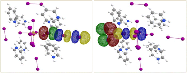
NBO analyses shed light on the two different types of Te–I⋯I2 close-contacts in compounds 1–3. SOPT-calculated stabilization energies for these interactions are listed in Table 3 and isosurface renderings of the NBOs involved shown in Fig. 9. As expected from % vdW overlap, the stronger interaction is between the end-on bound I2 and the [TeI6]2− octahedron, with a stabilization energy ranging from 13.2 to 17.5 kcal mol−1 in all three complexes (Table 3). The donor NBO consists of a lone pair of electrons on a tellurium-bound iodide, and the acceptor NBO, of an antibonding σ*-type orbital localized on I2. This end-on interaction can geometrically be considered a type I halogen bond (contact angels θ1 = θ2 = ∼180°). In the case of end-on halogen bonding in 1–3, the large stabilization energy and charge transfer character demonstrated by our computational analyses does not strictly meet the definition of a type I interaction. The side-on-I2–[TeI6]2− interaction, a bifurcated halogen bond geometrically analogous to a typical type II halogen bond, is significantly weaker, ranging from ca. 3.0–4.8 kcal mol−1 (Table S1†), with the donor NBOs consisting of I2 lone pairs and acceptor NBO of a Te–I antibonding σ*-type orbital.| Compound | Halogen bonded species | Closest halogen vdW overlap % | Stab. Energy (kcal mol−1) |
|---|---|---|---|
| 1 | [TeI6]2−⋯I2 (end-on) | 82.1 | 17.8 |
| 2 | [TeI6]2−⋯I2 (end-on) | 83.0 | 15.4 |
| 3 | [TeI6]2−⋯I2 (end-on) | 85.0 | 13.1 |
| 4 | [TeI6]2−⋯I2 | 83.7 | 20.1 |
| 5 | [TeI6]2−⋯I3 (end-on) | 91.2 | 8.91 |
| 6 | [TeI6]2−⋯HIPy | 98.1 | 1.58 |
In all three complexes, each [TeI6]2− octahedron is also surrounded by four side-on bound and two end-on bound I2 molecules, resulting in non-negligible contributions to overall stabilization energies (Table S1†) from the former. It is worth noting that the nature of this side-on, bifurcated halogen bond is very different in each compound, presumably owing to perturbations introduced by the organic cations and the resulting overall packing of the structures. This is most evidently seen in 3, in which (a) a weak halogen bond is present between iodopyridine and [TeI6]2− (% vdW ≈ 97%), and (b) the side-on-I2–[TeI6]2− interaction is no longer bifurcated. Also of note is that only a subset of the four I2 molecules are involved in bifurcated halogen bonding in all three complexes (three in 1, three in 2 and only one in 3). These changes in the second sphere environment are most likely due to packing effects of the changing organic cations in 1–3 (HPy > HClPy > HIPy).
Halogen bonding in 4: (HPyz)2[TeI6]·I2
Compared to compounds 1–3, compound 4 exhibits a different second sphere coordination scheme between [TeI6]2− and I2 (recall Fig. 3). There are four I2 molecules engaged in a halogen-bond with the [TeI6]2− octahedron, with varying Te–I⋯I2 distances and Te–I–I2 angles. Although the atoms involved in halogen-bonding, the % vdW overlap of the closest contacts (Table 3), and the associated donor and acceptor NBOs are all comparable or the same, the geometry of this interaction is quite different compared to those seen in compounds 1–3. In general, halogen bonds are extremely directional, and this perhaps explains why, at ca. 20.1 kcal mol−1, the strongest halogen bond in compound 4 is also the strongest of all six compounds reported here.Halogen bonding in 5: (HClPy)3[TeI6(I3)]
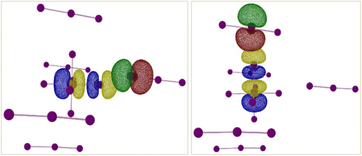
There are two types of TeI62−⋯I3− interactions present in compound 5 – end-on and side-on. NBO and SOPT calculations suggest that both these halogen-bonding interactions are approximately equal in strength (ca. 9 kcal mol−1 and 6 kcal mol−1 respectively). Both the end-on and side-on [TeI6]2−⋯I3− interactions occur via the same type of donor and acceptor NBOs (Fig. 10). The donor NBO consists of a lone pair of electrons on an iodine atom of I3−, while the acceptor NBO is a Te–I antibonding σ* orbital, reminiscent of the weaker side-on interactions in compounds 1–3.Halogen bonding in 6: (HBrPy)2[TeI6]
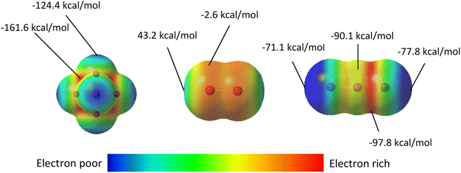
Compound 6 is the only compound reported herein that is devoid of any polyiodide species. Halogen bonding interactions do exist between the bromine substituent of the bromopyridinium cation and the [TeI6]2− octahedron. The SOPT-calculated stabilization energy of the [HBrPy]+⋯[TeI6]2− interaction (3.758(1) Å, 98.1% vdW) is only 2.48 kcal mol−1, and represents the strongest halogen–halogen interaction present in 6 that was included in our computational model. Halogen bonding interactions also exist between adjacent octahedra as illustrated previously, but these interactions were too computationally expensive to be modeled. In 6, a combination of hydrogen and carbon bonding also contribute to octahedron asymmetry. In 1–5, the longest Te–I bonds in the [TeI6]2− octahedron were simply those with the strongest halogen bonding between the tellurium bound halide and the surrounding polyiodides. However in 6, the longest Te–I bond (3.048(1) xzk Å) is not involved in halogen bonding with the [HBrPy]+ or an adjacent metal halide octahedron. The significant hydrogen and carbon bonding (Fig. 11) between a single tellurium bound iodine and the surrounding pyridinium species have a total stabilization energy of 6.85 kcal mol−1, spread between two different BrPy molecules. Therefore in 6, hydrogen and carbon bonding interactions trump halogen bonding in their overall stabilization energy and in their influence on the metal halide inner sphere bonding. A summation of stabilization energies for hydrogen, carbon, and halogen bonding in compound 6 can be seen in Table S2.† This 6.85 kcal mol−1 stabilization energy, spread over two BrPy, is still smaller than the 8.91 kcal mol−1 of the single strongest halogen bond in 5, and even smaller than those in 1–4.Electrostatic surface potential (ESP) maps on the surface of molecules are an additional tool to study noncovalent interactions and their role in the assembly of crystalline materials. Complementing the NBO calculations described above, the ESP maps in Fig. 12 adequately rationalize both the different modes of halogen bonding between [TeI6]2− and I2 or I3−, and their relative strengths. For compounds 1–4, in cases where the donor NBO is based on a Te-bound iodide, the most electron-rich portion of the [TeI6]2− octahedron (molecular electrostatic potential (MEP) energy plotted on a 0.002 ε·bohr−1 isodensity surface = −161.6 kcal mol−1) is sterically inaccessible to the neighboring I2 molecules. As a consequence, there is a clear trend in interaction energies as a function of the Te–I–I angles. The Te–I⋯I2 distances and Te–I–I angles for the strongest halogen bonds (XBs) in 1–4 are as follows: 3.252(1) Å, 167.4° [1]; 3.287(1) Å, 161.1° [2]; 3.367 Å(1), 151.6° [3]; 3.315(1) Å, 101.7° for [4]. As the most electrophilic region of I2 (MEP = 43.2 kcal mol−1) approaches the nucleophilic [TeI6]2− octahedron, the largest difference in MEPs is achieved as Te–I–I angle approaches 90°, typical of a type-II XB. The directional nature of the weaker bifurcated XB in 1–3, where I2 acts as the nucleophile, is also readily seen from Fig. 13. In compound 5, the orientation of the nucleophilic region (min, max MEP = −96.3 kcal mol−1, −90.1 kcal mol−1) local to the central iodine towards the [TeI6]2− octahedron results in the side-on binding mode of I3− shown in Fig. 10. The arrangement of iodine atoms in the end-on bound I3− is intriguing as there are two different I–I bond lengths in I3−. Let us consider the three distinct I atoms involved, referred to hereafter as Ia, Ib, and Ic (Fig. S20†). In our model, the two I–I distances are slightly uneven, with (Ia—Ib) ca. 2.86 Å and (Ib—Ic) at ca. 2.97 Å (typical of I3− in the solid state).58 An isodensity surface of 0.002 au around Ia has a maximal MEP value of ca. −71.1 kcal mol−1, while Ic has a maximal value of −77.8 kcal mol−1. It is interesting to note that it is Ia, and not Ic, that is oriented towards the [TeI6]2− octahedron. While this may seem at odds with the e−-donor nature of I3−, it is to be noted that each I3− unit is involved in four XBs at the same time (see Fig. S18†). Our simplified models for NBO analyses have included only one such interaction per I3−; a more extensive model would perhaps account for this behavior.
 | ||
| Fig. 13 Most significant halogen bonds in compounds 1–3, which include end-on and side-on I⋯I bonds geometrically matching type I and II halogen bonds respectively. | ||
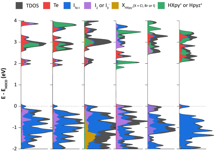
Whereas NBO calculations and ESP maps shed light on individual NCIs within our selected molecular models, DOS calculations (applying periodic boundary conditions) were also performed to highlight atomic contributions to the frontier crystal orbitals, and to support experimental bandgap measurements. In all six compounds, the frontier orbitals in the valence band are dominated by [TeI6]2−. An obvious difference between 1–5 and 6 is the presence of I2 or I3− in the former, while the latter lacks any polyiodide species. This has a clear effect on electronic structure, as can be seen from the sizeable contributions of I2/I3− to the valence band of 1–5, particularly closer to the band edge (Fig. 14). Similar contributions by polyiodide species are seen in the conduction band as well, except for the case of 4, for which the counter-cation, being a pyrazinium instead of a pyridinium, has its π* orbitals interspersed between the valence band and orbitals of TeI62− and I2. Also of note is the negligible contribution of the more electronegative chloro- and bromo-substituted pyridiniums to the valence band. IHIPy-based orbitals, owing to the more electropositive nature of iodine, have some minor contributions near the band edge.
Unlike in our previous work with tellurium chlorides and bromides,4 as well as antimony halides,19 we find here that the ‘intermediate bands’ just below the bulk of the conduction band are composed entirely of Te, ITe–I and I2/I3− orbitals, and have no contribution from π* orbitals of the organic cations, except in the case of 4. In 5, I3− orbitals and chloropyridinium π* orbitals are found in the conduction band edge. Whereas in 6, bromopyridinium π* orbitals dominate the lowest unoccupied orbitals, there is a non-negligible contribution from the [TeI6]2− units.
Bandgap measurements by diffuse reflectence spectroscopy
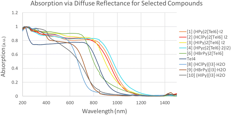
Fig. 15 shows a combination of diffuse reflectance spectra for 1–4, 6, and 8. The I2-containing materials (1–4) have the lowest energy bandgaps (1.0–1.17 eV) of the set. Previously reported [TeBr6]2− containing I2 species have higher energy bandgaps in the range of 1.4–1.5 eV (826–885 nm).59 Compound 6 (BrPy)2[TeI6] (green in Fig. 15) exhibits a bandgap of 1.42 eV, significantly higher in energy than 1–4. Compound 5 could not be produced in a reasonably pure state, and is therefore was not included in these measurements. The bandgaps of (HClPy)[I3]·H2O and TeI4 (Fig. 15 and Table 4) are shown to be 1.71 and 1.36 eV respectively, both higher in energy than each of the I2 containing compounds. These data suggest that the presence of I2 (in 1–4) and robust halogen bonding substantially affects the band gap of these materials. These results fit with our crystallographic metrics, with 1–4 exhibiting halogen bonding with a relatively large vdW overlap, and our computational metrics showing relatively high stabilization energies for [TeI6]2−⋯I2 halogen bonds.| Compound | Bandgap expt. (eV) | Bandgap DFT (eV) |
|---|---|---|
| [1] (HPy)2[TeI6]·I2 | 1.20 | 1.71 |
| [2] (HClPy)2[TeI6]·I2 | 1.21 | 1.86 |
| [3] (HIPy)2[TeI6]·I2 | 1.25 | 1.82 |
| [4] (HPyz)2[TeI6]·2(I2) | 1.18 | 1.54 |
| [6] (HBrPy)2[TeI6] | 1.42 | 2.12 |
| TeI4 | 1.36 | — |
| [8] (HClPy)[I3]·H2O | 1.71 | — |
Compiled metrics
A collection of the computational and crystallographic metrics presented so far can be seen in Fig. 16. [TeI6]2− octahedra generally tend to become more asymmetric with stronger halogen bonds (lower vdW %, Fig. 16a). Within compounds 1–3, the size of the halogen substituent on the pyridinium appears to affect the vdW overlap, with the closest I⋯I contact (lowest % vdW) and highest distortion of the [TeI6]2− belonging to 1, with less overlap (higher % vdW) in 2 and 3. Compounds 1–5 as a group also generally fit this trend, albeit less neatly than the subset of 1–3. 6 is expected to be an outlier in this case, having no polyiodides present. The dominance of hydrogen and carbon bonding over halogen bonding in 6, as seen from their relative stabilization energies, also contributes to its status as an outlier in this case. Stabilization energy in halogen bonding interactions increases with closer second sphere halogen–halogen interactions (low vdW overlap %, Fig. 16b). The highest stabilization energy for a halogen–halogen interaction belongs to 4, which is slightly larger than that for 1 or 2. In 1–4, a lower energy bandgap correlates with a more intimate vdW overlap, again indicating that relatively strong halogen bonding with polyiodide species lower the bandgap of 0 dimensional tellurium iodides relative to materials, namely compound 6, without such species (Fig. 16c and d). A plot of calculated bandgap vs. stabilization energy is present in Fig. S21.†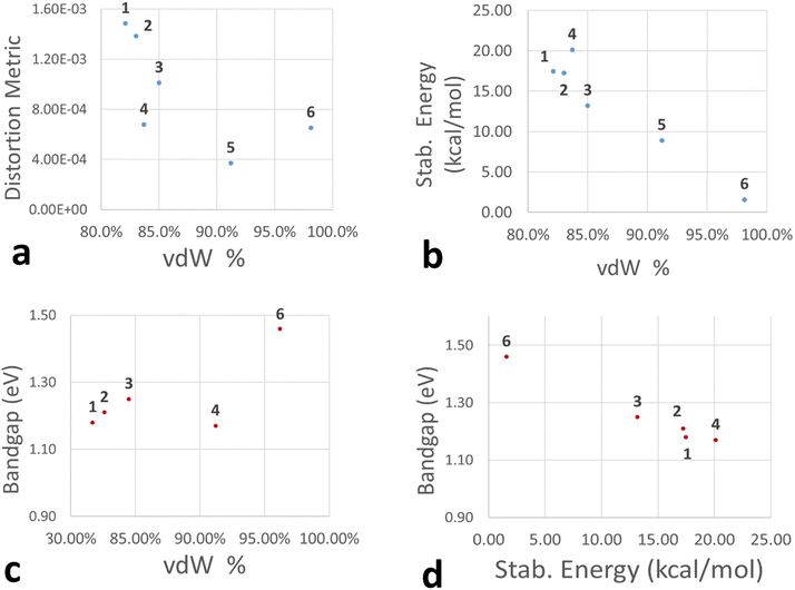 | ||
| Fig. 16 Plots showing correlation of distortion metric (a), vdW % overlap (a–c), stabilization energy (kcal mol−1, b and d), and bandgap (eV, c and d) of the most intimate halogen bond in 1–6. | ||
Elemental analysis
Results of elemental analysis (Table S3†) ranged from good agreement with theoretical values (compounds 4 and 5) to expectedly off (compounds 1–3, 6, 7–10). Excepting 4 and 5, most compounds exhibited lower than theoretical iodine content and conversely higher than expected C, H, N content. We ascribe this discrepancy to the impurity phases explicity identified by PXRD (e.g. TeI4 or iodide salts of pyridinium) as well as the volatilization of I2, evidenced by the brownish purple coloration of sample containers. The percent compositons of impurity phases have been tabulated in Fig. S4.† We note that the PXRD for compounds 4 and 5 (Fig. S4 and S6–S8†) revealed the presence of significant impurity phases, which did not seem to be reflected in the elemental anlysis results. Elemental analysis of compound 7 was predictably off-base, being a minority phase grown by evaporation on glass slides, as stated in the experimental section.Conclusions
We have presented a family of tellurium based halide perovskite derivatives and have evaluated the role of non-covalent interactions, mainly halogen bonding, in their assembly and material properties. Close contacts between [TeI6]2− and polyiodide species occur in 1–5, with crystallographic metrics indicating strong halogen bonding. Computational metrics reinforce this assertion, with 1–5 exhibiting stabilization energies of 10–15 kcal mol−1 between [TeI6]2− and I2 or I3− species, as determined by NBO and SOPT analyses. This relatively robust halogen bonding between the [TeI6]2− and polyiodide species seems to exacerbate the asymmetry of the metal halide octahedron, with greater vdW overlap correlating with octahedral asymmetry. Furthermore, the presence of I2 and the resulting halogen bonding directly affect the bandgap of the material, lowering it compared to materials without polyiodide species (compounds 1–4 vs. 6). Within 1–3, the size of the halogen substituent on the XPy affects the vdW overalp of the [TeI6]2−⋯I2 pair, with the overlap decreasing (higher vdW %) with increasing halogen size. 1–3 also exhibit a very similar second sphere interaction geometry, with 6 I2 halogen bonding with each [TeI6]2− octahedron. In 6, a combination of hydrogen and carbon bonding contribute to octahedral asymmetry, with the longest Te–I bond in the [TeI6]2− participating in said bonding. Hydrogen and carbon bonding between a single iodine of the [TeI6]2− octahedron and the surrounding pyridinium species have a stabilization energy of 6.85 kcal mol−1, more than the halogen bonding stabilization energy of 1.58 kcal mol−1 in the same compound. Future work could center around evaluating how the inner sphere of different metal halides are influenced by the relatively strong second sphere halogen bonds involving polyiodides. It is an open question how other perovskite-relevant metal halides, Sn or Bi halides e.g., would behave in the presence of polyiodide species.Conflicts of interest
There are no conflicts to declare.Acknowledgements
This material is based upon work supported by the Department of Energy National Nuclear Security Administration through the Nuclear Science and Security Consortium under Award Number DE-NA0003180. This report was prepared as an account of work sponsored by an agency of the United States Government. Neither the United States Government nor any agency thereof, nor any of their employees, makes any warranty, express or limited, or assumes any legal liability or responsibility for the accuracy, completeness, or usefulness of any information, apparatus, product, or process disclosed, or represents that its use would not infringe privately owned rights. Reference herein to any specific commercial product, process, or service by trade name, trademark, manufacturer, or otherwise does not necessarily constitute or imply its endorsement, recommendation, or favoring by the United States Government or any agency thereof. The views and opinions of authors expressed herein do not necessarily state or reflect those of the United States Government or any agency thereof. This work was completed in part with resources provided by the High Performance Computing Cluster at The George Washington University, Research Technology Services.References
- B. A. Connor, R. I. Biega, L. Leppert and H. I. Karunadasa, Dimensional reduction of the small-bandgap double perovskite Cs2AgTlBr6, Chem. Sci., 2020, 11, 7708–7715 RSC.
- M. D. Smith, E. J. Crace, A. Jaffe and H. I. Karunadasa, The diversity of layered halide perovskites, Annu. Rev. Mater. Res., 2018, 48, 111–136 CrossRef CAS.
- S. Zhao, W. Cai, H. Wang, Z. Zang and J. Chen, All-inorganic lead-free perovskite(-like) single crystals: synthesis, properties, and applications, Small Methods, 2021, 5, 1–35 Search PubMed.
- A. D. Nicholas, B. W. Walusiak, L. C. Garman, M. N. Huda and C. Cahill, Impact of noncovalent interactions on structural and photophysical properties of zero-dimensional tellurium(IV) perovskites, J. Mater. Chem. C, 2021, 3271–3286, 10.1039/d0tc06000c.
- P. R. Varadwaj, A. Varadwaj, H. M. Marques and K. Yamashita, Significance of hydrogen bonding and other noncovalent interactions in determining octahedral tilting in the CH3NH3PbI3 hybrid organic-inorganic halide perovskite solar cell semiconductor, Sci. Rep., 2019, 9, 1–30 CrossRef PubMed.
- P. Metrangolo, L. Canil, A. Abate, G. Terraneo and G. Cavallo, Halogen bonding in perovskite solar cells: a new tool for improving solar energy conversion, Angew. Chem Int., Ed., 2021, 61(11), e202114793 CrossRef PubMed.
- J. Guo, Y. Xu, W. Yang, B. Xiao, Q. Sun, X. Zhang, B. Zhang, M. Zhu and W. Jie, High-stability flexible X-ray detectors based on lead-free halide perovskite Cs2TeI6Films, ACS Appl. Mater. Interfaces, 2021, 13, 23928–23935 CrossRef CAS PubMed.
- Y. Xu, B. Jiao, T. B. Song, C. C. Stoumpos, Y. He, I. Hadar, W. Lin, W. Jie and M. G. Kanatzidis, Zero-dimensional Cs 2 TeI 6 Perovskite: solution-processed thick films with high x-ray sensitivity, ACS Photon., 2019, 6, 196–203 CrossRef CAS.
- S. Nagorny, Novel Cs2HfCl6 Crystal scintillator: recent progress and perspectives, Physics, 2021, 3, 320–351 CrossRef.
- R. Zhang, X. Mao, Y. Yang, S. Yang, W. Zhao, T. Wumaier, D. Wei, W. Deng and K. Han, Air-stable, lead-free zero-dimensional mixed bismuth-antimony perovskite single crystals with ultra-broadband emission, Angew. Chem., Int. Ed., 2019, 58, 2725–2729 CrossRef CAS PubMed.
- J. Almutlaq, J. Yin, O. F. Mohammed and O. M. Bakr, The benefit and challenges of zero-dimensional perovskites, J. Phys. Chem. Lett., 2018, 9, 4131–4138 CrossRef CAS PubMed.
- Z. Tan, J. Pang, G. Niu, J. H. Yuan, K. H. Xue, X. Miao, W. Tao, H. Zhu, Z. Li, H. Zhao, X. Du and J. Tang, Tailoring the electron and hole dimensionality to achieve efficient and stable metal halide perovskite scintillators, Nanophotonics, 2021, 10, 2249–2256 CrossRef CAS.
- R. Chiara, M. Morana, M. Boiocchi, M. Coduri, M. Striccoli, F. Fracassi, A. Listorti, A. Mahata, P. Quadrelli, M. Gaboardi, C. Milanese, L. Bindi, F. De Angelis and L. Malavasi, Role of spacer cations and structural distortion in two-dimensional germanium halide perovskites, J. Mater. Chem. C, 2021, 9, 9899–9906 RSC.
- Y. Han, S. Yue and B. B. Cui, Low-dimensional metal halide perovskite crystal materials: structure strategies and luminescence applications, Adv. Sci., 2021, 8, 1–21 Search PubMed.
- K. M. McCall, V. Morad, B. M. Benin and M. V. Kovalenko, Efficient lone-pair-driven luminescence: structure-property relationships in emissive 5s2Metal halides, ACS Mater. Lett., 2020, 2, 1218–1232 CrossRef CAS PubMed.
- P. Metrangolo, IUPAC definition of the halogen bond, Acta Crystallogr., Sect. A: Found. Adv., 2017, 73, C309 Search PubMed.
- P. Metrangolo, F. Meyer, T. Pilati, G. Resnati and G. Terraneo, Halogen bonding in supramolecular chemistry, Angew. Chem., Int. Ed., 2008, 47, 6114–6127 CrossRef CAS PubMed.
- B. Inscoe, H. Rathnayake and Y. Mo, Role of charge transfer in halogen bonding, J. Phys. Chem. A, 2021, 125, 2944–2953 CrossRef CAS PubMed.
- A. D. Nicholas, R. N. Halli, L. C. Garman and C. L. Cahill, Low-dimensional hybrid indium/antimony halide perovskites: supramolecular assembly and electronic properties, J. Phys. Chem. C, 2020, 124, 25686–25700 CrossRef CAS.
- H. A. Evans, J. L. Andrews, D. H. Fabini, M. B. Preefer, G. Wu, A. K. Cheetham, F. Wudl and R. Seshadri, The capricious nature of iodine catenation in I2 excess, perovskite-derived hybrid Pt(IV) compounds, Chem. Commun., 2019, 55, 588–591 RSC.
- G. Braathen and H. F. Pi-Tai Chou, Time-Resolved reaction of O2 with I- in aqueous solution, J. Phys. Chem., 1988, 6610–6615 CrossRef CAS.
- Q. Sun, X. Gong, H. Li, S. Liu, X. Zhao, Y. Shen and M. Wang, Direct formation of I3- ions in organic cation solution for efficient perovskite solar cells, Sol. Energy Mater. Sol. Cells, 2018, 185, 111–116 CrossRef CAS.
- SAINT Version 8.34a, Bruker AXS Inc., Madison Search PubMed.
- G. M. Sheldrick, SADABS, University of Göttingen, Germany, 2007 Search PubMed.
- G. M. Sheldrick, A short history of SHELX, Acta Crystallogr., Sect. A: Found. Crystallogr., 2008, 64, 112–122 CrossRef CAS PubMed.
- C. B. Hübschle, G. M. Sheldrick and B. S. X. Dittrich, A Qt graphical user interface for SHELXL, J. Appl. Crystallogr., 2011, 44, 1281–1284 CrossRef PubMed.
- O. V. Dolomanov, L. J. Bourhis, R. J. Gildea, J. A. K. Howard and H. Puschmann, OLEX2: a complete structure solution, refinement and analysis program, J. Appl. Crystallogr., 2009, 42, 339–341 CrossRef CAS.
- A. L. Spek, Single-crystal structure validation with the program PLATON, J. Appl. Crystallogr., 2003, 36, 7–13 CrossRef CAS.
- M. Burnett and C. Johnson, ORTEP-III: Oak Ridge Thermal Ellipsoid Plot Program for Crystal Structure Illustrations Oak Ridge National Laboratory Report ORNL-6895, 1996 Search PubMed.
- S. Parsons, Introduction to twinning, Acta Crystallogr., Sect. D: Biol. Crystallogr., 2003, 59, 1995–2003 CrossRef PubMed.
- M. J. Frisch, G. W. Trucks, H. B. Schlegel, G. E. Scuseria, M. a. Robb, J. R. Cheeseman, G. Scalmani, V. Barone, G. a. Petersson, H. Nakatsuji, X. Li, M. Caricato, a. V. Marenich, J. Bloino, B. G. Janesko, R. Gomperts, B. Mennucci, H. P. Hratchian, J. V. Ortiz, a. F. Izmaylov, J. L. Sonnenberg, F. Williams Ding, F. Lipparini, F. Egidi, J. Goings, B. Peng, A. Petrone, T. Henderson, D. Ranasinghe, V. G. Zakrzewski, J. Gao, N. Rega, G. Zheng, W. Liang, M. Hada, M. Ehara, K. Toyota, R. Fukuda, J. Hasegawa, M. Ishida, T. Nakajima, Y. Honda, O. Kitao, H. Nakai, T. Vreven, K. Throssell, J. a. Montgomery Jr., J. E. Peralta, F. Ogliaro, M. J. Bearpark, J. J. Heyd, E. N. Brothers, K. N. Kudin, V. N. Staroverov, T. a. Keith, R. Kobayashi, J. Normand, K. Raghavachari, a. P. Rendell, J. C. Burant, S. S. Iyengar, J. Tomasi, M. Cossi, J. M. Millam, M. Klene, C. Adamo, R. Cammi, J. W. Ochterski, R. L. Martin, K. Morokuma, O. Farkas, J. B. Foresman and D. J. Fox, G16_C01. Gaussian 16, Revision C.01, Gaussian, Inc., Wallin at, 2016 Search PubMed.
- A. D. Beck, Density-functional thermochemistry. III. The role of exact exchange, J. Chem. Phys., 1993, 98, 5648–5656 CrossRef.
- T. Lecklider, Maintainng a heathy rhythm, Eval. Eng., 2011, 50, 36–39 Search PubMed.
- F. Weigend, Accurate coulomb-fitting basis sets for H to Rn, Phys. Chem. Chem. Phys., 2006, 8, 1057–1065 RSC.
- F. Weigend and R. Ahlrichs, Balanced basis sets of split valence, triple zeta valence and quadruple zeta valence quality for H to Rn: design and assessment of accuracy, Phys. Chem. Chem. Phys., 2005, 7, 3297–3305 RSC.
- A. V. Krukau, O. A. Vydrov, A. F. Izmaylov and G. E. Scuseria, Influence of the exchange screening parameter on the performance of screened hybrid functionals, J. Chem. Phys., 2006, 125(22), 224106 CrossRef PubMed.
- R. Krishnan, J. S. Binkley, R. Seeger and J. A. Pople, Self-consistent molecular orbital methods. XX. A basis set for correlated wave functions, J. Chem. Phys., 1980, 72, 650–654 CrossRef CAS.
- A. D. McLean and G. S. Chandler, Contracted Gaussian basis sets for molecular calculations. I. Second row atoms, Z=11-18, J. Chem. Phys., 1980, 72, 5639–5648 CrossRef CAS.
- T. Lu and F. M. Chen, A multifunctional wavefunction analyzer, J. Comput. Chem., 2012, 33, 580–592 CrossRef CAS PubMed.
- G. Cavallo, P. Metrangolo, R. Milani, T. Pilati, A. Priimagi, G. Resnati and G. Terraneo, The halogen bond, Chem. Rev., 2016, 116, 2478–2601 CrossRef CAS PubMed.
- E. Faoro, G. M. de Oliveira, E. S. Lang and C. B. Pereira, Synthesis and structural features of new aryltellurenyl iodides, J. Organomet. Chem., 2010, 695, 1480–1486 CrossRef CAS.
- A. Bondi, Van der waals volumes and radii, J. Phys. Chem., 1964, 68, 441–451 CrossRef CAS.
- D. Meggiolaro, E. Mosconi and F. De Angelis, Modeling the Interaction of Molecular Iodine with MAPbI3: a probe of lead-halide perovskites defect chemistry, ACS Energy Lett, 2018, 3, 447–451 CrossRef CAS.
- L. Lanzetta, T. Webb, N. Zibouche, X. Liang, D. Ding, G. Min, R. J. E. Westbrook, B. Gaggio, T. J. Macdonald, M. S. Islam and S. A. Haque, Degradation mechanism of hybrid tin-based perovskite solar cells and the critical role of tin(IV) iodide, Nat. Commun., 2021, 12, 1–11 CrossRef PubMed.
- N. A. Belich, A. A. Petrov, P. O. Rudnev, N. M. Stepanov, I. Turkevych, E. A. Goodilin and A. B. Tarasov, From metallic lead films to perovskite solar cells through lead conversion with polyhalide solutions, ACS Appl. Mater. Interfaces, 2020, 12, 20456–20461 CrossRef CAS PubMed.
- D. Quiñonero, Sigma-hole carbon-bonding interactions in carbon-carbon double bonds: An unnoticed contact, Phys. Chem. Chem. Phys., 2017, 19, 15530–15540 RSC.
- V. Morad, Y. Shynkarenko, S. Yakunin, A. Brumberg, R. D. Schaller and M. V. Kovalenko, Disphenoidal zero-dimensional lead, tin, and germanium halides: highly emissive singlet and triplet self-trapped excitons and X-ray scintillation, J. Am. Chem. Soc., 2019, 141(25), 9764–9768 CrossRef CAS PubMed.
- X. Wang, W. Meng, W. Liao, J. Wang, R. G. Xiong and Y. Yan, Atomistic mechanism of broadband emission in metal halide perovskites, J. Phys. Chem. Lett., 2019, 10, 501–506 CrossRef CAS PubMed.
- M. E. Sun, T. Geng, X. Yong, S. Lu, L. Ai, G. Xiao, J. Cai, B. Zou and S. Q. Zang, Pressure-triggered blue emission of zero-dimensional organic bismuth bromide perovskite, Adv. Sci., 2021, 8, 1–7 Search PubMed.
- M. T. Casais, I. Laue-langevin, F.-G. Cedex and R. V. August Evolution of the Jahn - Teller distortion of MnO6 octahedra in RMnO3 perovskites (R) Pr, Nd, Dy, Tb, Ho, Er, Y): a neutron diffraction study. 917–923 ( 2000).
- T. V. Sedakova, A. G. Mirochnik and V. E. Karasev, Structure and luminescence properties of tellurium(IV) complex compounds, Opt. Spectrosc., 2011, 110, 755–761 CrossRef CAS.
- P. C. Srivastava, S. Bajpai, S. Bajpai, C. Ram, R. Kumar, J. P. Jasinski and R. J. T. Butcher, Potential synthons for charge-transfer complexes (involving hypervalent Te-I bonds) and serendipitous synthesis of the first triphenyl methyl phosphonium salts containing [C4H8TeI4]2- and [TeI6]2-anions, J. Organomet. Chem., 2004, 689, 194–202 CrossRef CAS.
- S. M. Närhi, R. Oilunkaniemi and R. S. Laitinen, Crystal structure of bis[(5-oxooxolan-3-yl)triphenylphosphanium] hexaiodidotellurate(IV), Acta Crystallogr., Sect. E: Struct. Rep., 2014, 70 CrossRef PubMed.
- T. V. Sedakova and A. G. Mirochnik, Luminescent and thermochromic properties of tellurium(IV) halide complexes with cesium, Opt. Spectrosc., 2016, 120, 268–273 CrossRef CAS.
- A. E. Maughan, A. M. Ganose, M. M. Bordelon, E. M. Miller, D. O. Scanlon and J. R. Neilson, Defect tolerance to intolerance in the vacancy-ordered double perovskite semiconductors Cs2SnI6 and Cs2TeI6, J. Am. Chem. Soc., 2016, 138, 8453–8464 CrossRef CAS PubMed.
- D. Ju, X. Zheng, J. Yin, Z. Qiu, B. Türedi, X. Liu, Y. Dang, B. Cao, O. F. Mohammed, O. M. Bakr and X. Tao, Tellurium-based double perovskites A2TeX6 with tunable band gap and long carrier diffusion length for optoelectronic applications, ACS Energy Lett., 2019, 4, 228–234 CrossRef CAS.
- S. A. Adonin, A. N. Usoltsev, A. S. Novikov, B. A. Kolesov, V. P. Fedin and M. N. Sokolov, One- and two-dimensional iodine-rich iodobismuthate(III) complexes: structure, optical properties, and features of halogen bonding in the solid state, Inorg. Chem., 2020, 59, 3290–3296 CrossRef CAS PubMed.
- F. Groenewald, C. Esterhuysen and J. Dillen, Extensive theoretical investigation: Influence of the electrostatic environment on the I3-⋯I3- anion-anion interaction, Theor. Chem. Acc., 2012, 131, 1–12 Search PubMed.
- A. V. Novikov, A. N. Usoltsev, S. A. Adonin, A. A. Bardin, D. G. Samsonenko, G. V. Shilov, M. N. Sokolov, K. J. Stevenson, S. M. Aldoshin, V. P. Fedin and P. A. Troshin, Tellurium complex polyhalides: narrow bandgap photoactive materials for electronic applications, J. Mater. Chem. A, 2020, 8, 21988–21992 RSC.
Footnote |
| † Electronic supplementary information (ESI) available. CCDC 2238872–2238881. For ESI and crystallographic data in CIF or other electronic format see DOI: https://doi.org/10.1039/d3ra00996c |
| This journal is © The Royal Society of Chemistry 2023 |


