DOI:
10.1039/D3RA00844D
(Paper)
RSC Adv., 2023,
13, 8955-8966
Charge transport and heavy metal removal efficacy of graphitic carbon nitride doped with CeO2
Received
8th February 2023
, Accepted 2nd March 2023
First published on 17th March 2023
Abstract
Doping of graphitic carbon nitride (g-C3N4) with semiconductors prevents electron–hole recombination and enhances adsorption capacity. This work investigates the synthesis of a water remediation material using g-C3N4 doped with CeO2 using two different techniques. The chemical structures of the doped g-C3N4 samples were confirmed using FTIR, XRD, XPS and their morphology was studied using SEM-EDX. Charge transport through the doped materials was illustrated by a comprehensive dielectric study using broadband spectroscopy. The ability of doped g-C3N4 to adsorb heavy metals was investigated thoroughly in the light of applying different parameters such as temperature, pH, time, and concentration. The results showed that the mode of doping of g-C3N4 by CeO2 strongly affected its adsorption capacity. However, g-C3N4 doped with CeO2 using the first mode adsorbed 998.4 mg g−1 in case of Pb2+ and 448 for Cd2+. Kinetic study revealed that the adsorption process obeyed PSORE as its qexpe is close to its qcale and the rate-controlling step involved coordination among the synthetic materials and the heavy metal ions. The recovery of Pb2+ and Cd2+ ions from various sorbents was investigated by utilizing different molar concentrations of HNO3 and indicated no significant change in the sorption capability after three different runs. This study has demonstrated an efficient method to obtain a highly efficient adsorbent for removing heavy metals from waste water.
1. Introduction
Graphitic carbon nitride (g-C3N4) is a nonmetallic polymer semiconductor, that has emerged as a desirable material due to its ease of preparation and eco friendliness. It has a 2D-triazine structure with versatile optical, thermal and chemical properties because of its high nitrogen content. These characteristics make it applicable in many fields, such as photocatalysis, water remediation, hydrogen evolution, energy storage and solar cells.1–5 The narrow band gap of g-C3N4 and its high light absorbing ability have improved solar cell devices that include it in their structure. An in-depth description and compositional analysis of g-C3N4 can be found in a review published by Miller et al.6 The review also illustrated the latest research work on the energy and sustainable applications of g-C3N4.
Intensive research on the intrinsic photocatalytic activity of g-C3N4 demonstrated high recombination of the hole–electron pairs formed by the photo-reaction because of its narrow band gap, and low absorption ability in the visible light range.7 However, the photocatalytic activity of g-C3N4 was found to be greatly improved upon doping with another co-catalyst.8,9 Non-metal doping of g-C3N4 is also reported to enhance its photocatalytic activity and retain the non-metallic character of the photocatalyst.10–12 Moreover, non-metals form covalent bonds by abstracting electrons from other compounds during reactions.13 Coupling of g-C3N4 with semiconductors to prevent recombination of photogenerated electron–hole pairs has also been reported.14–16 Great attention has been directed toward doping g-C3N4 with ordered mesoporous metal oxides in order to optimize its photocatalytic activity. Cerium oxide (CeO2) is a semiconductor characterized by its low cost, environmental friendliness, high oxygen storage capacity, and catalytic activity due to the fast change between Ce3+ and Ce4+ that might result in oxygen vacancies17,18 Cerium oxide is also characterized by space group Fm3m due to its stable cubic fluorite arrangement as a cerium cation present in a face-centered-cubic (fcc) construction. In this crystal structure the cerium ion is coordinated with eight adjacent oxygen ions while the oxygen ion is coordinated with four adjacent cerium ions.19,20 This coordination leads to the presence of defects that form CeO(2x−2). These defects play a vital role in the catalytic characteristics of cerium oxide. The preparation of a nanocomposite based on mesoporous CeO2 and g-C3N4 for CO2 reduction has been reported.21 The obtained nanocomposite showed enhanced charge carrier separation and high response to solar light. Kesarla et al. described a facial technique for the preparation of g-C3N4/CeO2 in the presence of L-arginine and studied its photocatalytic activity for degrading a herbicide.22 Researchers have described different methods for the preparation of g-C3N4/CeO2 toward photocatalytic applications that include mixing-calcination and hydrothermal synthesis.23–26
In this work, we describe the synthesis of g-C3N4/CeO2 by two different methods; the first route is the preparation of ceria nanoparticles in the presence of g-C3N4 nanosheets. The second one is the in situ reduction of a ceria precursor during the synthesis of g-C3N4. Characterization of the obtained nanocomposites was carried out using different techniques. Moreover, an alpha analyzer was employed to investigate the effect of preparation method and temperature on the mobility of charge carriers in the g-C3N4/CeO2 matrix. This work also demonstrates an alteration in the adsorption activity of g-C3N4 upon doping with ceria nanoparticles.
2. Experimental
2.1. Materials
Cerium ammonium nitrate was obtained from Merck Company, while urea was a product from ADWIC. All chemicals were used as received without further purification.
2.2. Instruments
An ATR-FTIR-VERTEX 80 (Germany) was employed for investigation of the chemical structure of the prepared pure and variously doped samples. The instrument was combined with a Platinum diamond ATR disk. The internal reflection was in the range of 400–4000 cm−1 with a resolution of 4 cm−1 and a refractive index of 2.4. The phase crystallinity and crystallite size were determined using X-ray diffraction (XRD) (Bruker AXS D8 advance) employing Cu-Kα radiation (λ = 0.15406 nm) in the 2θ range from 20° to 80°. The crystallite size of the phases present in the various solids was calculated according to the Scherrer eqn (1):27| |
d = Kλ/β1/2cos![[thin space (1/6-em)]](https://www.rsc.org/images/entities/char_2009.gif) θ θ
| (1) |
where β1/2 is the full width at half maximum (FWHM) of the major diffraction peaks of the crystalline phase, θ is the diffraction angle, λ is the X-ray wavelength, K is the Scherrer constant (0.89), and d is the average crystalline diameter. The area of the principal diffraction peak of the present phase was utilized to calculate the degree of crystallinity of that phase.28 A model K-alpha X-ray photoelectron spectrometer (XPS) was used under the following conditions: (I) monochromatic Al K-alpha radiation with an energy range of −10 to 1350 eV, (II) pot size 400 μm, (III) a pressure of 10−9 mbar and (IV) full and narrow spectrum pass energies of 200 eV and 50 eV, respectively. Sample morphologies were examined using a scanning electron microscope (SEM) fitted with an energy dispersive X-ray spectrometer (EDX) for elemental analysis, producing a gallery of microscopic images. The concentrations of Pb2+ and Cd2+ were determined using atomic absorption spectroscopy (AAS, Model: Varian AA240FS).
A high-resolution alpha analyzer from Novocontrol was employed to investigate the dielectric properties of the prepared samples in the frequency range 10−1–107 Hz, supported by a Novocontrol-Quatro temperature controller system using pure nitrogen as heating agent. The measurements were carried out at different temperatures ranging from −50 to 150 °C isothermally in 10 °C steps, and with a measurement error less than ± 0.5%. For dielectric measurements a sample (0.5 g) of milled powder was pressed into a stainless-steel mold at 30 MPa, sandwiched between two Teflon plates at 100 °C, and pressed at 30 MPa once again for film-formation, and left to reach an equilibrium state. During the dielectric measurements the film was sandwiched between two gold-plated brass electrodes in parallel plate configuration. More details about the broadband dielectric spectroscopy technique, its characteristics, and work theories have been published elsewhere.29–31
2.3. Preparation methods
2.3.1. Preparation of g-C3N4. Graphitic carbon nitride (g-C3N4) was prepared following the previously described method.32,33 In brief, 10 g of urea was heated in a muffle furnace using the following heating regime: 100 °C for 10 min, 200 °C, 300 °C for 10 min, then finally at 500 °C for 2 hours. A yellowish-white fine powder was formed, which was left to cool down.
2.3.2. Preparation of g-C3N4 doped with CeO2 (M1). A known mass of finely powdered g-C3N4 with 0.05 mol% cerium ammonium nitrate was dissolved in the minimum volume of distilled water necessary to make a paste to produce a solid doped with cerium. The paste was dried at 100 °C for two hours before being calcinated at 500 °C.
2.3.3. Synthesis of g-C3N4 doped with CeO2 (M2). For the second mode of doping, the same recipe was used but a calculated quantity of cerium ammonium nitrate (0.05 mol%) was mixed with a definite amount of urea. A minimum volume of distilled water was added to make a paste which was dried at 100 °C and then calcinated at 500 °C for 2 h.
2.4. Adsorption experiments
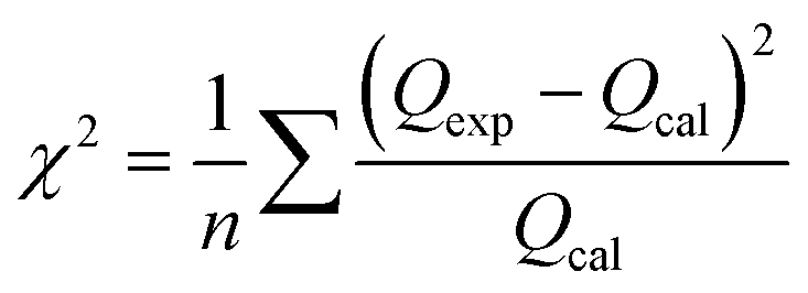
Using batch adsorption techniques, the uptake of Pb2+ and Cd2+ ions onto prepared pure g-C3N4 and different doped samples was investigated. 0.05 g of each sample was mixed at room temperature with a series of 20 mL solution of Pb2+ and Cd2+ (6.24 mmol L−1, pH 6) on a shaker set to 120 rpm to optimize the Pb2+ and Cd2+ ion adsorption behavior of the prepared solids. It was investigated how various factors, including pH, lead and cadmium ion concentrations, temperature, and time, affect the sorption of Pb2+ and Cd2+. The pH range of 2.1 to 8.1 was chosen to demonstrate the impact of pH. The pH value was adjusted in each experiment by utilizing 0.1 M HNO3 and 0.1 M NaOH solutions for 3 h. The initial concentrations of Pb2+ and Cd2+ ions were varied from 0.01 to 6.24 mmol L−1 at pH 6.0 to obtain the kinetic sorption isotherms. At a pH of 6.3, an adsorbent dose of 50 mg, and a temperature range of 25–50 °C for 60 minutes, the effect of temperature on the uptake of Pb2+ and Cd2+ on various adsorbents was examined. The concentration of Pb2+ and Cd2+ ions was 6.24 mmol L−1. Up to 150 min of adsorbent contact time with waste ions were studied at a temperature of 25 °C, while the resting conditions remained the same as before. Approximately 200 mL of 6.24 mmol L−1 Pb2+ and Cd2+ solutions were combined and magnetically stirred (120 rpm) for an hour and a half. A portion of the mixture was taken out and filtered through 1.0 μm membrane filters, and the filtrate was then subjected to atomic absorption spectroscopy over a predetermined period. To study the sorption kinetics, the experimental data were simulated as pseudo-first-order and pseudo-second-order reactions. However, to further fit the sorption isotherms of these experimental data, kinetic models based on the Langmuir and Freundlich isotherms were also used. Each sorption experiment was conducted three times. Calculating the correlation coefficients and/or mean chi-squared error (χ2), as shown in eqn (2), allowed us to assess how well the experimental data fit the investigated kinetic and equilibrium models:| |
 | (2) |
where n indicates how many data points there are. The terms Qexp and Qcal denote the experimental and calculated values for equilibrium sorption capacity, respectively. Eqn (3) was used to ikcalculate how much lead or cadmium would be adsorbed onto the various prepared solids:where V (mL) is the solution volume; Ci and Ce (mmol L−1) are the initial and equilibrium concentrations of Pb2+ and Cd2+ in the solution, respectively; and m (g) is the mass of the obtained solid.
2.5. Desorption experiments
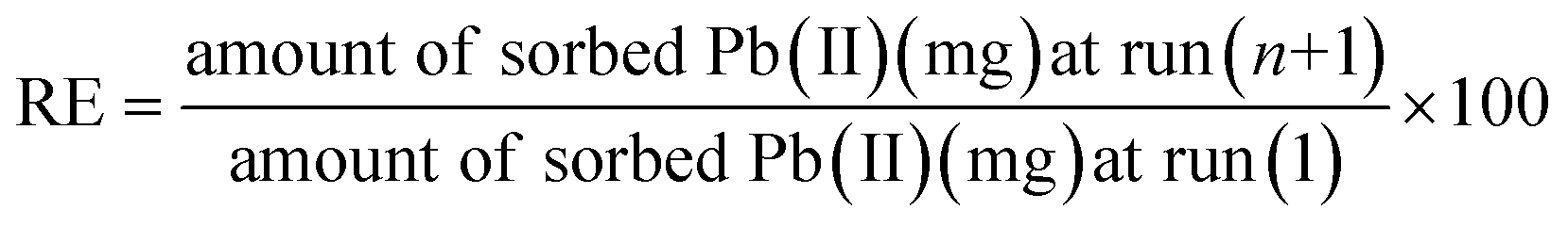
By soaking the contaminated specimen sorbents in 20 mL of 0.4–0.6 M HNO3 solution for 60 min, during which the surface was recovered, it was possible to determine whether the adsorbed lead ions on the surface of the as-prepared sorbents could be released.34,35 The cleaned sorbent that had already been used twice was then carefully removed and thoroughly washed with distilled water in preparation for a third cycle of impregnation with wastewater. While this was going on, the mass balance eqn (4) was used to determine the released metal concentration in the filtrate and to calculate the regeneration efficiency (RE%):| |
 | (4) |
where n is the cycle number.
Investigations into kinetics are comparable to experiments into equilibrium, but equilibrium was attained over time. Eqn (4) and (5), respectively, can be used to demonstrate pseudo-first-order and pseudo-second-order calculations:34,35
| | |
ln(qe − qt) = lnqe − k1t
| (5) |
where
qt is the quantity of ions adsorbed at time
t (min),
qe is the quantity adsorbed at equilibrium, and all values are in mg g
−1,
k1 (min
−1) is the pseudo-first-order adsorption rate constant.
| | |
t/qt = 1/k2qe2 + t/qe
| (6) |
where
k2 (g(mg min)
−1) is the pseudo-second-order adsorption rate constant. The parameters of pseudo-first-order values (
qe,
qcal, and
k1) and pseudo-second-order values (
qe,
qcal, and
k2) in the equations can be estimated from the linear graph of log(
qe −
qt) against
t and
t/
qt versus t, respectively (
eqn (5) and
(6)) by working out the slopes and intercepts of the straight lines.
3. Results and discussion
3.1. XRD investigation
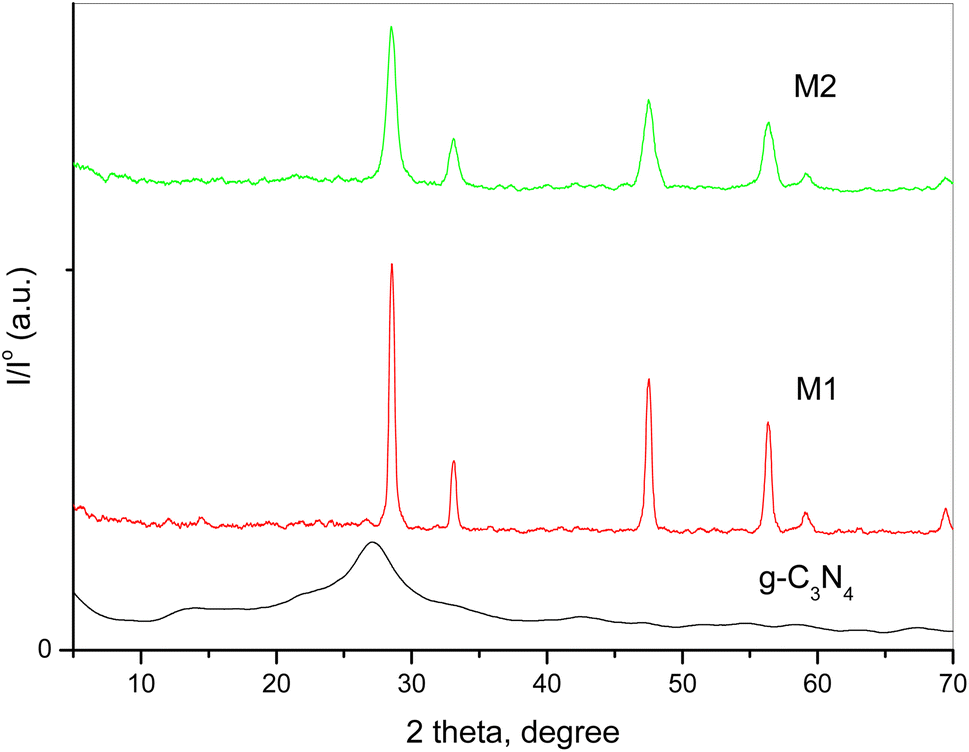
XRD spectroscopy was used to investigate pure g-C3N4 and variously doped samples. The collected XRD patterns of the different solids are shown in Fig. 1. A previous study demonstrated that pristine g-C3N4 has two diffraction characteristic peaks at 2θ = 12.7° and 27.2° belonging to the system of aromatic graphitic C3N4 (JCPDS card no. 87-1526).26,32 The figure shows that the peak intensities of CeO2 were influenced by the preparation technique. The doped samples show diffraction peaks at 2θ = 28.54°, 33.09°, 47.5° and 56.38°, which could be assigned to the (111), (200), (220) and (311) crystalline planes of cubic CeO2 NPs (JCPDS card no. 81-0792). The intensity of the CeO2 peaks was 58 a.u. for the M1 sample and 17 a.u. for the M2 sample. The disappearance of the characteristic peak of g-C3N4 might be due to distortion of the sp2 carbon sites into an amorphous structure.36 Moreover, the peak intensity of CeO2 was influenced by the preparation technique as the different preparation processes of the two composites resulted in a variation in the diffraction patterns, crystallite size and degree of crystallinity, as displayed in Table 1. These results confirm the strong contact of CeO2 not only over the surface of g-C3N4 but within the interlayer spacing as well.
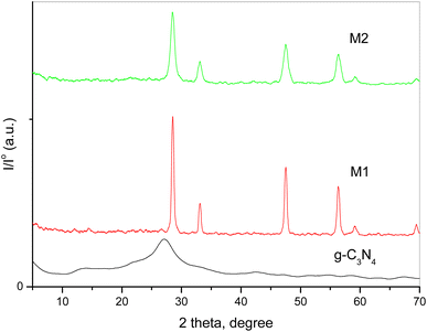 |
| | Fig. 1 XRD patterns of pure g-C3N4 and variously doped samples. | |
Table 1 Crystallite size and degree of crystallinity of g-C3N4 and variously doped samples
| Sample |
Crystallite size, nm |
Degree of crystallinity |
| g-C3N4 |
0.9 |
17.3 |
| M1 |
49.3 |
56.2 |
| M2 |
16.3 |
25.7 |
3.2. FTIR investigation
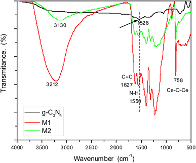
Investigation of the chemical structure of the prepared materials was carried out by FTIR spectroscopy (Fig. 2). The spectrum of pure g-C3N4 showed bands at 1627 cm−1 corresponding to C![[double bond, length as m-dash]](https://www.rsc.org/images/entities/char_e001.gif) C and 1528 cm−1 for N–H bending.33 By examining the spectra of doped samples M1 and M2, we can find the same bands but in slightly shifted positions due to the interaction with g-C3N4. The hydroxyl group of attached water molecules appeared at 3212 cm−1, while bands related to N–H bending are shifted to 1550 cm−1 in both samples. This shift can be attributed to hydrogen bonding between hydrogen atoms in g-C3N4 and oxygen atoms in the oxide doping material. Bands in the region 1200–1350 cm−1 can be assigned to C–N stretching. Moreover, doped samples showed a band at 758 cm−1 characteristic of the stretching vibration of Ce–O–Ce. This band should appear below 700 cm−1, but it had shifted owing to the electrostatic interaction with the host material.
C and 1528 cm−1 for N–H bending.33 By examining the spectra of doped samples M1 and M2, we can find the same bands but in slightly shifted positions due to the interaction with g-C3N4. The hydroxyl group of attached water molecules appeared at 3212 cm−1, while bands related to N–H bending are shifted to 1550 cm−1 in both samples. This shift can be attributed to hydrogen bonding between hydrogen atoms in g-C3N4 and oxygen atoms in the oxide doping material. Bands in the region 1200–1350 cm−1 can be assigned to C–N stretching. Moreover, doped samples showed a band at 758 cm−1 characteristic of the stretching vibration of Ce–O–Ce. This band should appear below 700 cm−1, but it had shifted owing to the electrostatic interaction with the host material.
 |
| | Fig. 2 FTIR spectra of g-C3N4 and its doped samples M1 and M2. | |
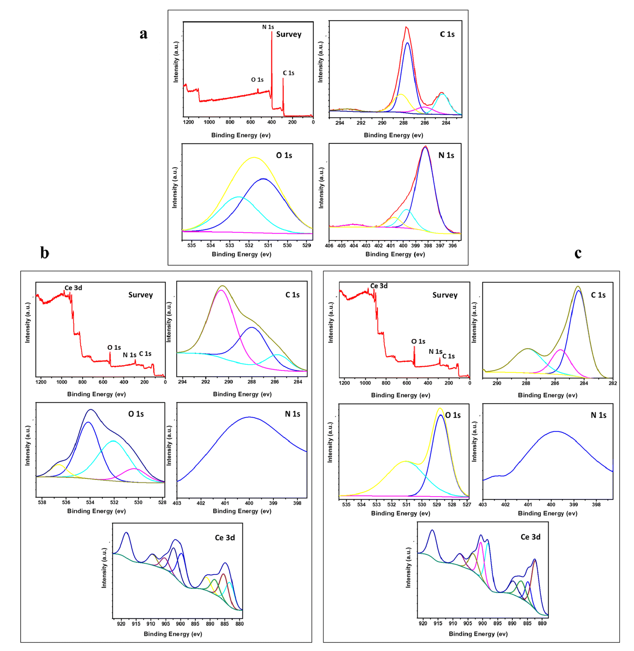
3.3. X-ray photoelectron spectroscopy (XPS)
XPS analysis of the surface chemical composition of the various prepared samples is demonstrated in Fig. 3. The samples doped with CeO2 contain only Ce, O, N, and C elements with no other peaks, signifying the purity of the prepared samples. In Fig. 3a, the peaks presented around 287.8 and 284.5 eV are the core level peak of C (1s) that belong to three coordinated C atoms and carbon contamination, respectively. The peak of N (1s) occurring at 398 eV corresponds to sp2-hybridized nitrogen.37 The presence of these peaks refers to the formation of g-C3N4.37 The presence of a broad peak at about 400 eV for Nl in the two doped samples emphasizes the incorporation of nitrogen into CeO2.38 Fig. 3b shows the presence of three signals of C 1s, N 1s, and O 1s located at 284 eV, 400 eV, and 528 eV, respectively. These peaks reveal that the major elements in the doped samples are C and N. The C 1s spectrum shows three peaks, as revealed in Fig. 3b and c, located at 285 eV, 288 eV and 291 eV. These peaks belong to C–C coordination of the surface transverse carbon, NC–N coordination of the sp2-hybridized and π-excitation, respectively.38,39 The broad peak located at 400 eV for N 1s corresponds to overlapping of the sp2-hybridized nitrogen atoms in CN–C with that of amino group.40
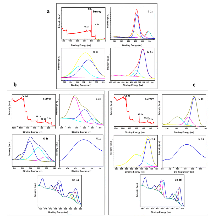 |
| | Fig. 3 XPS spectra of g-C3N4 and variously doped samples (a) g-C3N4, (b) M1, and (c) M2. | |
The peak of Ce 3d dissociated into 8 weak signals, as shown in Fig. 3b and c. These peaks confirm the presence of two types of cerium: Ce3+ and Ce4+. The peaks near 900.2 and 893 eV accompanied by peaks at 885 eV and 883.7 eV, which are weaker than those at 917.5 and 903.2 eV, suggest that the major oxidation state is Ce4+ accompanied by Ce3+ as a minor phase.41 The presence of signals for O 1s at 535 eV, 534 eV and 531.4 eV in Fig. 3b relates to the generation of oxygen vacancies, which decreases the coordination number from 8 to 4 in the case of Ce4+ constructing a fluorite arrangement. This might lead to high metal ion uptake, which will be discussed in the next section of this work.
3.4. Scanning electron microscope and elemental study
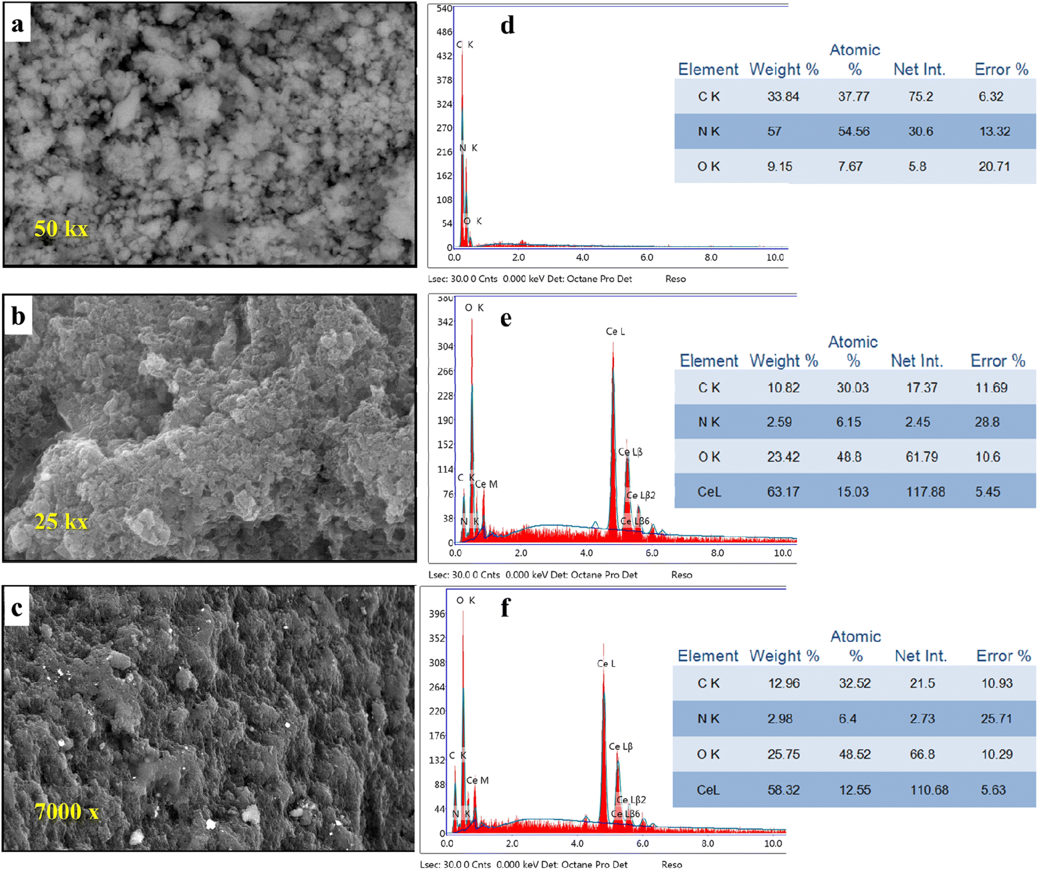
Scanning electron microscopy with EDX was used to investigate the variations in the morphology of g-C3N4 after the addition of CeO2 (Fig. 4a–c).
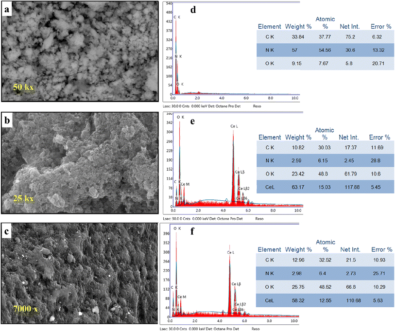 |
| | Fig. 4 SEM images of (a) g-C3N4, (b) M1, (c) M2, and EDX images of (d) g-C3N4, (e) M1 and (f) M2 (photographs are of different magnification for clarity). | |
The pure g-C3N4 sample shows an ill-defined form resembling ruptured toweling. So, this structure cannot give any perfect information. But, the morphology was changed significantly by the addition of CeO2 using different techniques. By observing image 4b, we can see the formation of aggregates comprised small particles. This change in surface morphology confirms the successful inclusion of CeO2 into g-C3N4. Further modification of the morphology of the formed composite and obvious variation could be observed in the case of composite M2 (image 4c). Investigation of surface elemental composition for the three samples revealed that the atomic percentage of Ce element depends on the mode of preparation. Comparing the percentage of N and C in the pure sample (Fig. 4d) with their values in doped samples (Fig. 4e and f) we can see that the concentrations of N and C were decreased on the surface by the presence of CeO2. This might be interpreted as the replacement of the parent elements (C and N) by Ce. This decrease in the concentrations of C and N by doping with CeO2 can be explained by the formation of an electron–hole pair that results in ionic vacancies in the matrix.14–16,42–44 These vacancies might play a role in the uptake of heavy metal ions, as will be discussed in Section 3.6.
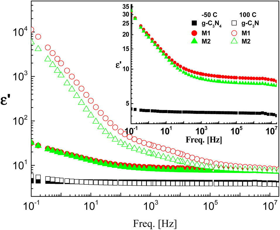
3.5. Dielectric and electrical study
The effect of CeO2 and the method of doping on the dielectric and electrical properties of g-C3N4 are investigated in the frequency range 100 mHz–20 MHz and at temperatures between −50 and 100 °C. The dielectric permittivities of the investigated samples at the lowest and highest measurement temperatures are shown in Fig. 5. Pristine g-C3N4 showed perfect dielectric features, since its permittivity was influenced neither by frequency nor by temperature, at least not in the ranges considered. This is accompanied by lower values of dielectric loss tangent ranging between 0.001 and 0.1 depending on measuring temperature and frequency (not discussed here). According to these results, g-C3N4 can be considered to be applicable in the field of electronics as an ideal dielectric material.
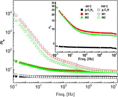 |
| | Fig. 5 Typical permittivity spectra of the three investigated samples at two selected temperatures, namely, −50 °C (closed symbols) and 100 °C (open symbols) on a log–log scale plot. The inset shows rescaling of the spectra at −50 °C. The error is in the range of the size of the symbol. | |
Doping of g-C3N4 with CeO2 by two modes increases the values of permittivity remarkably from 4.5 to 8.5 for the M1 and 7.5 for the M2 mode at frequencies down to 1 kHz. At lower frequencies starting from 1 kHz there is a slight increase (which may be linear) with decreasing frequency, reaching about 35 at 0.1 Hz for both nanocomposites, as shown in the rescaled inset in the figure. This agrees well with the fact that the replacement of the parent elements C and N by Ce leads directly to a remarkable decrease in the concentrations of C and N by doping with CeO2 and the formation of electron–hole pairs, resulting in ionic vacancies in the matrix, as stated before. The contribution of conductivity in describing the transport of the generated ions is the reason for such behavior at lower frequencies. On the other hand, the fluctuation of the generated charge carriers lags behind the alteration in the applied field at higher frequencies which is the cause of the constant values of permittivity at higher frequencies starting from 1 kHz (independent of frequency and temperature as well as the mode of synthesis). One has to conclude that the number-density of the generated free charge carriers seems to be nearly independent of the mode used for preparation and hence there is no significant difference between the modes even in the lower frequency range. At higher temperature (100 °C), the figure shows three distinguishable trends for the two nanocomposites M1 and M2. At frequencies ranging from 100 Hz down to 0.1 Hz the permittivity increases linearly and abruptly as the frequency decreases, reaching about 5900 for M2 and 11350 for M1. This may indicate that the mobility at elevated temperatures is higher in the case of M1, which will enhance its DC-conductivity. The second trend between 100 Hz and 100 kHz shows the well-known shoulder originating from interfacial polarization – usually called Maxwell–Wagner–Siller (MWS) polarization. It is now considered a characteristic feature of heterogeneous systems.45–47 Fig. 6 shows the electric loss modulus, M′′, at 100 °C for the two nanocomposites M1 and M2 illustrated graphically against frequency. This is a very useful tool for obtaining a close look at the dielectric properties at higher temperatures when the two parts of the complex permittivity are very high as a direct response to both electrode polarization and charge carrier transport.
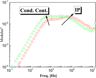 |
| | Fig. 6 The determined electric loss modulus, M′′, vs. frequency for the two samples M1 and M2 at 100 °C. | |
M′′ = ε′′2/(ε′2 + ε′′2) in that case is very useful since it suppresses the undesirable capacitance effects that may originate from electrode contacts and hence provides a clear view of the DC conduction and dipole relaxation.48–52 The behavior of M′′ with frequency for the two samples is characterized by two different relaxation peaks. The first one is positioned in the region of the conductivity contribution, whereas the second peak is in the intermediate range of frequency. The latter is assigned as interfacial polarization, IP (sometimes called space-charge polarization). From close inspection of the 1st peak that originated from transport of charge carriers, it is very interesting to note that the peak intensity of M2 is higher than that of M1 (which may be attributed to the number density, n, of the free charge carriers), the maximum peak position of M2 is positioned at higher frequency indicating the hopping process is faster, i.e. the mobility, μ, is higher. One should expect close values of DC-conductivity for both samples, according to the relation: σdc = qnμ, in which n is the number density of charge carriers and μ is their mobility.53–56
The complex conductivity function: σ* = σ′ + iσ′′, when the external electric field is low, i.e. in the linear response region, is related to complex permittivity, according to the relation:
where
εo is the permittivity of a vacuum and
ω denotes the radial frequency, respectively. This equation implies that
σ′′ =
εoωε′.
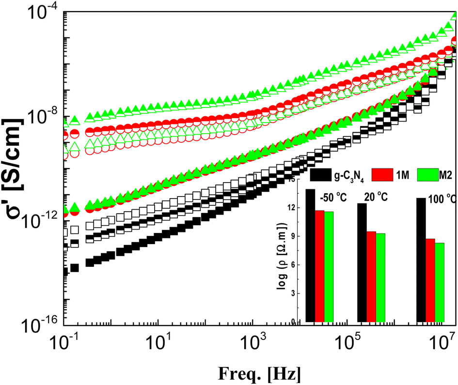
The real part of the complex conductivity function σ′ is illustrated graphically against frequency for the samples under investigation at three selected temperatures in Fig. 7. The CeO2 free sample shows the lowest values of AC-conductivity even at high temperature with a gradual decrease overall in the considered frequency window, with decreasing frequency meaning that g-C3N4 is an insulator. The two composite samples M1 and M2 have the same insulation features at −50 °C as g-C3N4, although they have higher values of conductivity. This may be attributed to the freezing of the charge carriers at such low temperatures, leading to an insulation feature without any effect from the preparation mode. As the measurement temperature increases to 20 and 100 °C, the AC-conductivity spectra are characterized in the low-frequency regime by lack of dependence on frequency. The value of this plateau directly yields the DC-conductivity, σdc, in addition to a characteristic frequency (fc). At fc, dispersion sets in and turns into a power law at higher frequencies. The typical resistivity values, ρdc (=1/σ′ taken at 0.1 HZ) of the three samples and at the three measurement temperatures considered are plotted as shown in the inset to the figure. The spectra investigated in the freezing temperature range (−50 °C) coincided for M1 and M2, indicating identical insulation features for both modes. However, the addition of CeO2 significantly decreased the resistivity of pure g-C3N4, so the preparation method has a very slight effect, especially at lower temperatures.
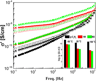 |
| | Fig. 7 The frequency dependence of the real part of the complex conductivity, σ′, for the three investigated samples g-C3N4 (black squares), M1 (red circles) and M2 (green triangles) at three selected temperatures: −50 °C (closed), 20 °C (upper closed) and 100 °C (open). The inset shows the resistivity, ρ′ (=1/σ′), at 0.1 Hz for the three samples at the three indicated temperatures. | |
3.6. Metal ion sorption
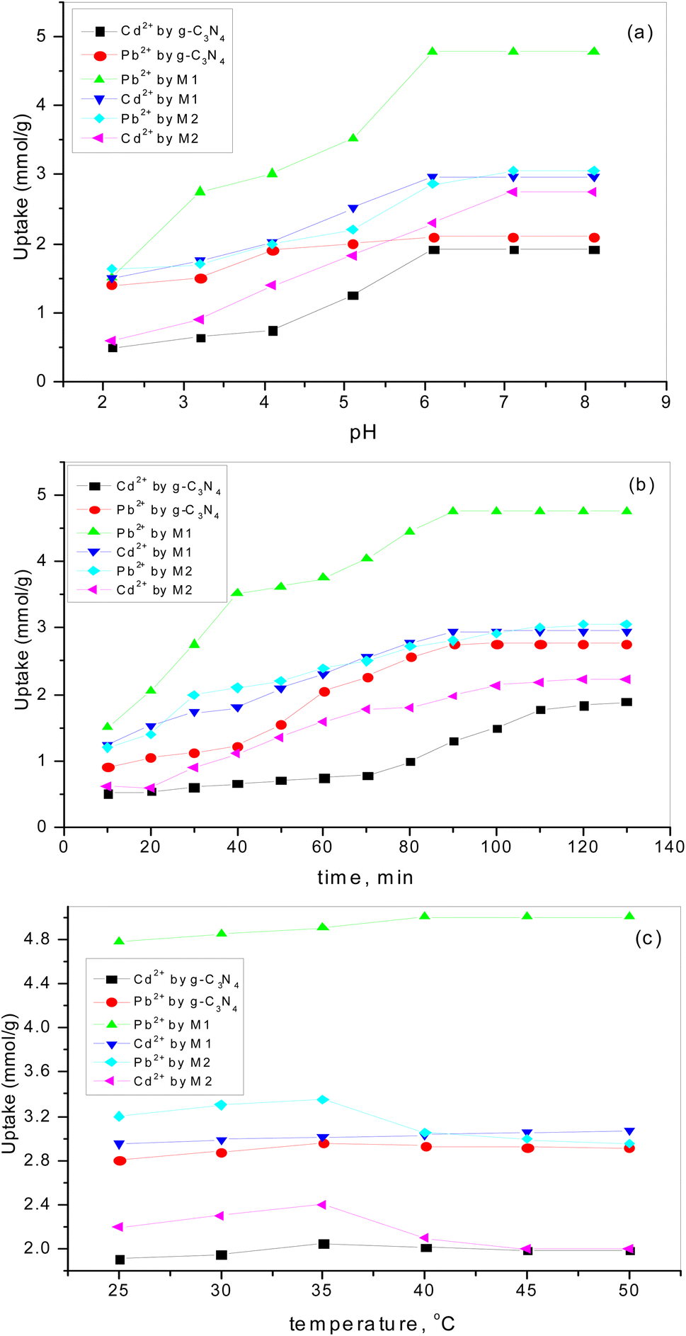
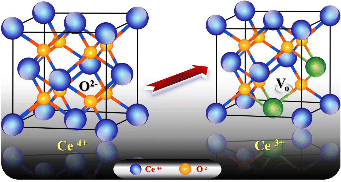
3.6.1. Effect of pH. The charge of the adsorbent surface and the surface binding sites are strongly dependent on the change in solution pH.57–61 In our previous work32 it was found that an increase in pH in the presence of g-C3N4 results in increases in Pb2+ and Cd2+ uptake of 50% and 284%, respectively. As has been discussed,32 at low pH (less than 3) there was competition for adsorption sites between heavy metal ions and a higher concentration of H3O+. While, with an increase in pH up to 6, the coordination and chelating capability for Pb2+ and Cd2+ increased due to the weakness of the protonation of the amino groups. If the pH is increased to more than 6, there is poor adsorption capacity as metal ions might form a precipitate of insoluble hydroxide in the ion solution. Fig. 8a shows the increase in adsorption capacity for both Pb2+ and Cd2+ by doping g-C3N4 with CeO2 by the two modes. The increases in Pb2+ uptake were 128% and 45% for the first mode and second mode of doping, respectively. Also, the uptake of Cd2+ was increased by 55% for sample M1 and by 43% for sample M2. These results indicate that doping of g-C3N4 by CeO2 as well as the mode of doping strongly affected the adsorption capacity. The high Pb2+ and Cd2+ uptakes are related to the percentage of cerium on the surface (as confirmed and discussed in Section 3.4) which might be favorable for a secondary removal mechanism for both cations. The secondary mechanism might be illustrated by the presence of an oxygen vacancy in the crystal lattice of CeO2 (Fig. 9) since CeO2 exhibits high oxygen storage capacity and good surface acidic–basic properties.62 The synergetic influence of g-C3N4 and CeO2-doping might be attributed to the electronic interaction between Ce4+ and g-C3N4, as Ce4+ present in the CN lattice might improve the redox cycle. The mechanism can be illustrated as the absorption of visible-light resulting in the formation of e− and h+ (eqn (8)). Oxygen stored in the CeO2 matrix can react with e− in the conduction band (CB) of g-C3N4, converting it to ·O2− (eqn (9)). This was confirmed by electrical measurement, as has been previously discussed in this work (c.f. Section 3.5). Also, a number of these electrons (e−) can shift to the special Ce 4f, and transfer to the surface to combine with Pb2+ or Cd2+. So, the increase in Ce concentration on the surface of g-C3N4 improved the adsorption uptake. This might explain the high uptake of sample M1 (c.f. Section 3.6) and could be taken in combination with the effect of g-C3N4, as shown in our previous work.32 However, it can be further discussed in the light of the increase in negative charge due to the existence of C–NH– groups. The presence of nitrogen atoms in different forms leads to an increase in Lewis and Brønsted basic sites.32 The basic –NH2 group is strongly bonded with Pb2+ and/or Cd2+ cations. The mechanism of adsorption is shown in the following equations (eqn 10–13):| | |
CN + hν → CN (h+) + CN (e−)
| (8) |
| | |
Pb2+ + nH2O ↔ Pb(H2O)2+n
| (10) |
| | |
Pb(H2O)2+n ↔ Pb(H2O)n−1 + H+
| (11) |
| | |
nPb2+ + mH2O ↔ Pbn(OH)m2n−m + mH+
| (12) |
| | |
2(–NH3+) + Pb2+ ↔ (–NH2)2Pb2+ + 2H+
| (13) |
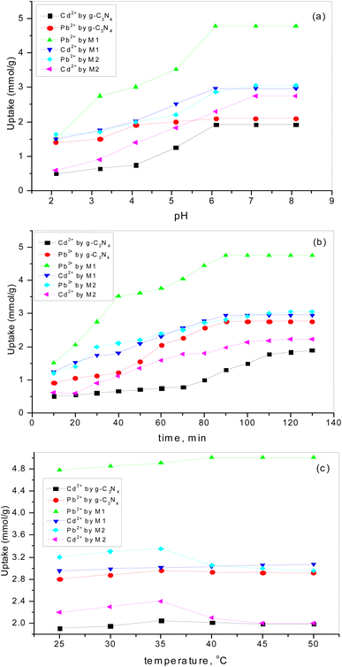 |
| | Fig. 8 The influence of (a) pH, (b) contact time, (c) temperature on Pb2+ and Cd2+ adsorption by g-C3N4 and variously doped samples. | |
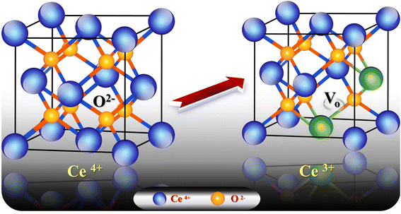 |
| | Fig. 9 Crystal lattice of CeO2 in the presence of one oxygen vacancy accompanied by two generated Ce3+ species. | |
3.6.2. The influence of contact time. Fig. 8b shows the rapid increase in adsorption for all adsorbents at the beginning (up to 60 min). The results obtained revealed that 100 min was sufficient time to reach equilibrium. The decrease in active sites over time might be the reason for the decreasing sorption uptake. This is in good agreement with our previous studies,57–62 which revealed that the adsorption rate is directly proportional to the amount of vacant sites. So, the time chosen for additional studies was 60 min.
3.6.3. The influence of temperature on adsorption uptake. Adsorption uptake of Pb2+ and Cd2+ by pure and variously doped samples was studied in the temperature range 25–50 °C (Fig. 8c). It was found that the adsorption of Pb2+ and Cd2+ by doped samples is dependent on the mode of doping and the type of heavy metal ion. Fig. 8c reveals that a higher uptake of Pb2+ could be observed by increasing the temperature for the solid doped by the first mode while the opposite trend is shown by the solid doped by the second mode. But Cd2+ uptake was almost unaffected by temperature for the solid doped by the first mode while it was greatly decreased by increasing the temperature for the solid doped by the second mode. These results were in good agreement with those previously mentioned (c.f. Section 3.4.1) and can be attributed to the increasing electron charge due to the presence of more cerium cations. However, the uptake of Pb2+ is much higher than that of Cd2+ since lead ions have higher electronegativity than cadmium ions. Additionally, Pb2+ is characterized by higher ionic radius and redox potential, which are favorable for adsorption.63,64
3.6.4. Kinetic study. A kinetic study is essential to investigate the route of adsorption and determine the rate-controlling step of a reaction.65 The relationship between the number of adsorbates adsorbed on the adsorbents (qt) and the time of the reaction (t) is described by adsorption kinetics. Pseudo-first-order (PFOR)66 and pseudo-second-order (PSOR) kinetic models of adsorption are frequently employed.67 The data of qexpe for pseudo-first-order and pseudo-second-order are given in Table 2. The results reveal that the adsorption process obeyed PSORE as its qexpe was close to its qcale. This means that the rate-controlling step involved coordination among the synthetic materials and the heavy metal ions.68 That is, the negative centers of the adsorbate attracted Pb2+ and Cd2+ (c.f. eqn (8)). Hence, the mechanism of sorption might be interpreted as follows: firstly, heavy metal ions move to the adsorbent surface. The second step is the diffusion of metal ions through pores, from the outside to the inside. For the sample treated by cerium there is a synergetic effect as electrons on the surface attach to positive ions (Pb2+ and Cd2+) and also the presence of an NH– group on the g-C3N4 surface that can work as an active site.32
Table 2 Correlation coefficients of Pb2+ and Cd2+ adsorption by g-C3N4 and variously doped samples and kinetic model constants
| Kinetic model |
Parameters |
Cd2+ by g-C3N4a |
Pb2+ by g-C3N4a |
Cd2+ by M1 |
Pb2+ by M1 |
Cd2+ by M2 |
Pb2+ by M2 |
| These data adapted from ref. 32. |
| Pseudo-first-order model |
K1 (min−1) |
0.0410 |
0.0390 |
0.0068 |
0.009 |
0.0084 |
0.0089 |
| qe (mmol g−1) |
4.8 |
3.9 |
2.9 |
2.4 |
3.2 |
2.8 |
| R2 |
0.880 |
0.900 |
0.79 |
0.74 |
0.82 |
0.78 |
| X2 |
0.70 |
0.80 |
0.73 |
0.68 |
0.77 |
0.78 |
| Pseudo-second-order model |
K2 (g mmol−1 min−1) |
0.006 |
0.004 |
0.0208 |
0.02 |
0.027 |
0.019 |
| qe2 (mmol g−1) |
4.2 |
3.77 |
3.5 |
2.9 |
3.4 |
3.1 |
| R2 |
0.9960 |
0.9630 |
0.993 |
0.994 |
0.989 |
0.985 |
| X2 |
8.4 × 10⁻³ |
3.2 × 10⁻³ |
2.2 × 10⁻³ |
2.9 × 10⁻³ |
3.6 × 10⁻³ |
3.8 × 10⁻³ |
3.6.5. Metal ion recovery. By employing various molar concentrations of HNO3, the recovery of Pb2+ and Cd2+ ions from different sorbents was studied. The recovery effectiveness (RE%) of the prepared solids' for Pb2+ and Cd2+ adsorption are listed in Table 3. The outcomes showed that using 0.6 M HNO3 enabled excellent metal desorption (more than 90%). Additionally, the data show that the sorption capability is nearly identical to the values found in the first run and that the proficiency is noticeably higher for the solids treated with CeO2 using both methods. These outcomes demonstrated incredible productivity and workability the prepared solids for three iterative cycles of sorption–desorption, which can be used to remove heavy metals from wastewater.69
Table 3 Regeneration efficiency (RE%) of Pb2+ and Cd2+ on different prepared solids
| Sorption regeneration cycle |
Regeneration efficiency (%) |
| Cd2+ by g-C3N4a |
Pb2+ by g-C3N4a |
Cd2+ by M1 |
Pb2+ M1 |
Cd2+ by M2 |
Pb2+ by M2 |
| HNO3 (mol L−1) |
HNO3 (mol L−1) |
HNO3 (mol L−1) |
HNO3 (mol L−1) |
HNO3 (mol L−1) |
HNO3 (mol L−1) |
| 0.4 |
0.5 |
0.6 |
0.4 |
0.5 |
0.6 |
0.4 |
0.5 |
0.6 |
0.4 |
0.5 |
0.6 |
0.4 |
0.5 |
0.6 |
0.4 |
0.5 |
0.6 |
| These data adapted from ref. 32. |
| First |
— |
— |
— |
— |
— |
— |
— |
— |
— |
— |
— |
— |
— |
— |
— |
— |
— |
— |
| Second |
83.3 |
89.7 |
92.6 |
79.6 |
89.6 |
95.1 |
87.4 |
93.4 |
98.2 |
88.3 |
93.9 |
98.8 |
86.7 |
92.9 |
97.3 |
92.7 |
94.5 |
97.4 |
| Third |
80.7 |
87.5 |
90.7 |
75.4 |
88.0 |
92.8 |
83.3 |
92.7 |
97.8 |
84.4 |
93.1 |
97.9 |
82.8 |
91.9 |
96.8 |
91.3 |
93.2 |
96.7 |
| Fourth |
78.5 |
84.9 |
88.1 |
73.3 |
85.4 |
90.7 |
80.8 |
90.6 |
96.5 |
81.2 |
91.3 |
97.0 |
80.0 |
90.8 |
95.9 |
88.6 |
91.8 |
95.1 |
3.6.6. Evaluation with other adsorbents. A comparison between g-C3N4 treated with CeO2 and further adsorbents for the adsorption capacity of Pb2+ and Cd2+ in earlier studies is given in Table 4. g-C3N4 doped with CeO2 is a favorable adsorbent for Pb2+ and Cd2+ from waste solution. So, the synergistic effect between g-C3N4 and CeO2 resulted in higher adsorption uptake of the prepared sample compared with other adsorbents.
Table 4 Comparison of Pb2+ and Cd2+ uptake efficiency using g-C3N4 doped with CeO2
| Heavy metal |
Adsorbent |
Max. adsorption capacity, mg g−1 |
Ref. |
| Pb2+ |
g-C3N4 nanosheets |
136.57 |
70 |
| Forest waste |
769.2 |
71 |
| g-C3N4 |
436.8 |
32 |
| g-C3N4 doped by CeO2 (M1) |
998.4 |
Present work |
| Cd2+ |
g-C3N4 nanosheets |
123.21 |
70 |
| Fe3O4 modified with poly-dopamine |
25 |
72 |
| g-C3N4 |
399.4 |
32 |
| g-C3N4 doped by CeO2 (M1) |
448 |
Present work |
4. Conclusions
Novel materials for heavy metal removal based on graphitic carbon nitride g-C3N4 have been prepared by two methods, namely M1 and M2. The chemical structures of the obtained materials were confirmed using different analytical techniques. Investigation of the surface chemical composition by XPS analysis confirmed the incorporation of nitrogen into CeO2 in the two doped samples. Moreover, the presence of Ce3+ accompanied by Ce4+ was confirmed. Dielectric spectroscopy was utilized to study mobility and charge transport within the prepared materials. The results demonstrated that the replacement of the parent elements C and N by Ce had occurred and led to the formation of an electron–hole pair that resulted in ionic vacancies in the matrix. The adsorption efficacy of doped samples M1 and M2 compared to g-C3N4 was studied against Pb2+ and Cd2+ and by changing different parameters. The kinetics of the adsorption process showed that the rate-controlling step involved coordination among the synthetic materials and heavy metal ions. Comparison of the adsorption efficiency of doped g-C3N4 with removal of other heavy metals depicted the superiority of the doped g-C3N4 for wastewater remediation.
Author contributions
Professor Dr Mona Abdel Rehim participated in the synthesis and characterization of the materials and writing the first draft of the manuscript. Prof. Dr G. Turky was responsible for dielectrics spectroscopy part including discussion of the results. Prof. Dr A. Badawy synthesized the doped materials, performed the adsorption experiments and interpreted the results. All the authors contributed equally in the writing and revising the final manuscript.
Conflicts of interest
There are no conflicts to declare.
Acknowledgements
Financial support of this work from National Research Center (NRC) is acknowledged.
References
- X. Yang, H. Wang, X. Lu, D. Cui and S. Zhang, Acta Chim. Sin., 2009, 67, 1166 CAS.
- Q. Han, F. Zhao, C. Hu, L. Lingxiao, Z. Zhang, N. Chen and L. Qu, Nano Res., 2015, 8, 1718–1728 CrossRef CAS.
- X. Cai, J. He, L. Chen, K. Chen, Y. Li, K. Zhang, Z. Jin, J. Liu, C. Wang, X. Wang, L. Kong and J. Liu, Chemosphere, 2017, 171, 192 CrossRef CAS PubMed.
- S. P. Adhikari, Z. D. Hood, V. W. Chen, K. L. More, K. Senevirathne and A. Lachgar, Sustain. Energy Fuels, 2018, 2, 2507 RSC.
- X. Yang, L. Zhao, S. Wang, J. Li and B. Chi, J. Materiomics, 2021, 7, 728–741 CrossRef.
- T. S. Miller, A. Belen Jorge, T. M. Suter, A. Sella, F. Corà and P. F. McMillan, Phys. Chem. Chem. Phys., 2017, 19, 15613 RSC.
- X. C. Wang, K. Maed, A. Thomas, K. Takanabe, G. Xin, J. M. Carlsson, K. Domen and M. Antonietti, Nat. Mater., 2009, 8, 75–80 Search PubMed.
- N. Cheng, J. Tian, Q. Liu, C. Ge, A. H. Qusti, A. M. Asiri, A. O. Al- Youbi and X. Sun, ACS Appl. Mater. Interfaces, 2013, 5, 6815 CrossRef CAS PubMed.
- J. Yu, K. Wang, W. Xiao and B. Cheng, Phys. Chem. Chem. Phys., 2014, 16, 11492 RSC.
- J. Fang, H. Fan, M. Li and C. Long, J. Mater. Chem. A, 2015, 3, 13819 RSC.
- C. Lu, R. Chen, X. Wu, M. Fan, Y. Liu, Z. Le, S. Jiang and S. Song, Appl. Surf. Sci., 2016, 360, 1016 CrossRef CAS.
- Z. A. Lan, G. Zhang and X. Wang, Appl. Catal., B, 2016, 192, 116 CrossRef CAS.
- L. Jiang, X. Yuan, Y. Pan, J. Liang, G. Zeng, Z. Wu and H. Wang, Appl. Catal., B, 2017, 217, 388 CrossRef CAS.
- J. Zhang, Y. Wang, J. Jin, J. Zhang, Z. Lin, F. Huang and J. Yu, ACS Appl. Mater. Interfaces, 2013, 5, 10317 CrossRef CAS PubMed.
- S. Zhou, Y. Liu, J. Li, Y. Wang, G. Jiang, Z. Zhao, D. Wang, A. Duan, J. Liu and Y. Wei, Appl. Catal., B, 2014, 158–159, 20 CrossRef CAS.
- L. Sun, X. Zhao, C.-J. Jia, Y. Zhou, X. Cheng, P. Li, L. Liu and W. Fan, J. Mater. Chem., 2012, 22, 23428 RSC.
- Z. M. Yu Ren and P. G. Bruce, Chem. Soc. Rev., 2012, 41, 4909–4927 RSC.
- Y. Wang, F. Wang, Y. Chen, D. Zhang, B. Li, S. Kang, X. Li and L. Cui, Appl. Catal., B, 2014, 147, 602 CrossRef CAS.
- D. Zhang, X. Du, L. Shi and R. Gao, Dalton Trans., 2012, 41, 14455 RSC.
- C. Sun, H. Li and L. Chen, Energy Environ. Sci., 2012, 5, 8475 RSC.
- M. Li, L. Zhang, M. Wu, Y. Du, X. Fan, M. Wang, L. Zhang, Q. Kong and J. Shi, Nano Energy, 2016, 19, 145 CrossRef CAS.
- M. K. Kesarla, M. O. Fuentez-Torres, M. A. Alcudia-Ramos, F. Ortiz-Chi, C. G. Espinosa-González, M. Aleman, J. G. Torres-Torres and S. Godavarthi, J. Mater. Res. Technol., 2019, 8, 1628 CrossRef CAS.
- L. Huang, Y. Li, X. Y. Hui, J. Xu, K. Xia and H. Wang, et al., RSC Adv., 2013, 3, 22269 RSC.
- L. Tan, J. Xu, X. Zhang, Z. Hang, Y. Jia and S. Wang, Appl. Surf. Sci., 2015, 356, 447 CrossRef CAS.
- N. Tian, H. Huang, C. Liu, F. Dong, T. Zhang and X. Du, et al., J. Mater. Chem. A, 2015, 3, 17120 RSC.
- X. She, H. Xu, H. Wang, J. Xia, Y. Song and J. Yan, et al., Dalton Trans., 2015, 44, 7021 RSC.
- B. D. Cullity, Elements of X-Ray diffraction, Publishing Co. Wesley, Reading, 2nd edn, 1978, p. 102 Search PubMed.
- G. A. El-Shobaky, N. S. Yehia, H. M. Hassan and A. A. Badawy, Can. J. Chem. Eng., 2009, 87, 792 CrossRef CAS.
- S. S. Omara, G. Turky, A. Ghoneim, A. F. Thünemann, M. H. Abdel Rehim and A. Schonhals, Polymer, 2017, 121, 64 CrossRef CAS.
- F. Kremer, Dielectric spectroscopy–yesterday today and tomorrow, J. Non-Cryst. Solids, 2002, 305, 1 CrossRef CAS.
- G. M. Turky and R. A. El-Adly, J. Mol. Liq., 2017, 242, 1 CrossRef CAS.
- M. H. Abdel Rehim, A. A. Badawy and G. Turky, J. Phys. Chem. Solids, 2022, 167, 110741 CrossRef CAS.
- M. A. Moussa, M. H. Abdel Rehim and G. M. Turky, J. Phys. Chem. Solids, 2021, 158, 110243 CrossRef CAS.
- A. Kumar, G. Sharma, A. Kumari, C. Guo, M. Naushad, D. V. N. Vo, J. Iqbal and F. J. Stadler, Appl. Catal. B, 2021, 284, 119808 CrossRef CAS.
- M. Tang, Y. Ao, C. Wang and P. Wang, Appl. Catal. B, 2020, 268, 118395 CrossRef CAS.
- A. F. Ghanem, A. A. Badawy, M. E. Mohram and M. H. Abdelrehim, J. Inorg. Organomet. Polym. Mater., 2019, 29, 28 Search PubMed.
- S. Q. Xiao and O. Takai, Thin Solid Films, 1998, 31, 137 CrossRef.
- C. Chang, Y. Fu, M. Hu, C. Wang, G. Shan and L. Zhu, Appl. Catal., B, 2013, 142–143, 553 CrossRef CAS.
- V. N. Khabashesku, J. L. Zimmerman and J. L. Margreve, Chem. Mater., 2000, 12, 3264 CrossRef CAS.
- D. Gao, Q. Xu, J. Zhang, Z. Yang, M. Si, Z. Yan and D. Xue, Nanoscale, 2014, 6, 2577 RSC.
- P. Burroughs, A. Hamnett, A. F. Orchard and G. Thornton, J. Chem. Soc., Dalton Trans., 1976, 1686 RSC.
- G. A. El-Shobaky, H. M. A. Hassan, N. S. Yehia and A. A. Badawy, J. Non-Cryst. Solids, 2010, 356, 32 CrossRef CAS.
- N. A. Hassan, G. A. Fagal, A. A. Badawy and G. A. El-Shobaky, Open J. Appl. Sci., 2013, 3, 92 Search PubMed.
- A. A. Badawy, A. M. Rashad, S. M. Ibrahim and S. M. El-Khouly, Recent Innov. Chem. Eng., 2020, 13, 156 Search PubMed.
- A. G. Darwish, G. Turky, M. Y. Hassaan and A. Ghoneim, Mater. Res. Express., 2019, 6, 105039 CrossRef CAS.
- D. Wang, X. Zhang, J. W. Zha, J. Zhao, Z. Dang and H. G. Mand, Polymer, 2013, 54, 1916 CrossRef CAS.
- Z. M. Dang, J. K. Yuan, J. W. Zha, Z. Tao, S. T. Li and H. Guo-Hua, Prog. Mater. Sci., 2012, 57, 660 CrossRef CAS.
- G. M. Turky, A. M. Fayad, G. T. El-Bassyouni and M. Abdel-Baki, J. Mater. Sci.: Mater. Electron., 2021, 32, 22417 CrossRef CAS.
- A. N. Papathanassiou, O. Mykhailiv, L. Echegoyen, I. Sakellis and M. E. Plonska-Brzezinska, J. Phys. D: Appl. Phys., 2016, 49, 285305 CrossRef.
- M. A. Mahdy, I. K. El-Zaway and G. M. Turky, Curr. Appl. Phys., 2019, 19, 787 CrossRef.
- E. Kolonelou, A. N. Papathanassiou and E. Sakellis, Mater. Chem. Phys., 2019, 223, 140 CrossRef CAS.
- F. H. Margha, G. T. El-Bassyouni and G. M. Turky, Ceram. Int., 2019, 45, 11838 CrossRef CAS.
- P. H. O. Neto, W. F. Cunha, R. Gargano and G. M. Silva, J. Phys. Chem. A, 2009, 113, 14975 CrossRef PubMed.
- M. A. Moussa, A. M. Ghoneim, M. H. Abdel Rehim, Sh. A. Khairy, M. A. Soliman and G. M. Turky, J. Appl. Polym. Sci., 2017, 134, 45415 CrossRef.
- J. R. Sangoro, G. Turky, M. Abdel Rehim, C. Iacob, S. Naumov, A. Ghoneim, J. Karger and F. Kremer, Macromolecules, 2009, 42, 1648 CrossRef CAS.
- A. Abdukarimov, I. S. M. Noor, O. Mamatkarimov and A. M. Arof, Polymers, 2022, 34(2), 232 CAS.
- Sh. M. Ibrahim, A. F. Ghanem, D. H. Sheir and A. A. Badawy, J. Environ. Chem. Eng., 2022, 10, 108588 CrossRef CAS.
- A. A. Badawy, A. F. Ghanem, M. A. Yassin, A. Y. Youssef and M. H. AbdelRehim, Environ. Nanotechnol. Monit. Manag., 2021, 16, 100501 CAS.
- M. G. A. Saleh, A. A. Badawy and A. F. Ghanem, Inorg. Chem. Commun., 2019, 108, 107508 CrossRef CAS.
- S. M. Ibrahim, A. A. Badawy and H. A. Essawy, J. nanostructure chem., 2019, 9, 281 CrossRef CAS.
- A. A. Badawy, S. M. Ibrahim and H. A. Essawy, J. Inorg. Organomet. Polym. Mater., 2020, 30(5), 1798–1813 CrossRef CAS.
- Y. Ma, W. Gao, Z. Zhang, S. Zhang, Z. Tian, Y. Liu, J. C. Ho and Y. Qu, Surf. Sci. Rep., 2018, 73, 1 CrossRef.
- A. H. Sulaymon, S. H. Ebrahim and M. J. Ridha, Environ. Sci. Pollut. Res., 2013, 20, 175 CrossRef CAS PubMed.
- S. J. Allen and P. A. Brown, J. Chem. Technol. Biotechnol., 1995, 62, 17 CrossRef CAS.
- M. Matouq, N. Jildeh, M. Qtaishat, M. Hindiyeh and M. Q. A. Syouf, J. Environ. Chem. Eng., 2015, 3, 775 CrossRef CAS.
- S. Lagergren, K. Sven. vetensk.akad. handl., 1898, 24, 1 Search PubMed.
- Y. S. Ho and G. McKay, Process Biochem., 1999, 34, 451 CrossRef CAS.
- P. Staron, J. Chwastowski and M. Banach, J. Clean. Prod., 2017, 149, 290 CrossRef CAS.
- M. E. El-Naggar, E. K. Radwan, H. R. M. Rashdan, S. T. El-Wakeel, A. A. Koryam and A. Sabtd, RSC Adv., 2022, 12, 18923 RSC.
- G. Xiao, Y. Wang, S. Xu, P. Li, C. Yang, Y. Jin, Q. Sun and H. Su, Chin. J. Chem. Eng., 2019, 27, 305–313 CrossRef CAS.
- I. R. Chowdhury, S. Chowdhury, M. A. J. Mazumder and A. Al-Ahmed, Appl. Water Sci., 2022, 12, 185 CrossRef CAS PubMed.
- T. Lei, S.-J. Li, F. Jiang, Z.-X. Ren, L.-L. Wang, X.-J. Yang, L.-H. Tang and S.-X. Wang, Nanoscale Res. Lett., 2019, 14, 352 CrossRef PubMed.
|
| This journal is © The Royal Society of Chemistry 2023 |
Click here to see how this site uses Cookies. View our privacy policy here. 
 Open Access Article
 This Open Access Article is licensed under a Creative Commons Attribution-Non Commercial 3.0 Unported Licence
 *b and
Gamal M. Turkyc
*b and
Gamal M. Turkyc