 Open Access Article
Efficient removal of norfloxacin from water using batch airlift-electrocoagulation reactor: optimization and mechanisms analysis†
Xuege Gu,
Junfeng Li *,
Xueting Feng,
Wenying Qu,
Wenhuai Wang and
Jiankang Wang
College of Water Conservancy and Architectural Engineering, Shihezi University, Shihezi, 832000, PR China. E-mail: ljfshz@126.com
First published on 17th March 2023
Abstract
In this study, we developed an airlift-electrocoagulation (AL-EC) reactor to remove norfloxacin (NOR) from water. Six parameters influencing NOR removal were investigated, and the possible removal mechanism was proposed based on flocs characterization and intermediates analysis. The performances for treating different antibiotics and removing NOR from 3 types of water were also evaluated. The best NOR removal efficiency was obtained with the iron anode and aluminum cathode combination, a current density of 2 mA cm−2, an initial pH of 7, a treatment time of 32 minutes and an air flow rate of 200 mL min−1, the supporting electrolyte type was NaCl, and the initial NOR concentration was 10 mg L−1. Flocs adsorption and electrochemical oxidation were the main ways to remove NOR from water. The average removal efficiency of the AL-EC reactor exceeded 60% of the different antibiotic concentrations in artificial and real water. The highest NOR removal rate reached 93.48% with an operating cost of 0.153 USD m−3. The present work offers a strategy for NOR removal from water with high efficiency and low cost, showing a huge potential for the application of the AL-EC in antibiotic contaminated water treatment.
1 Introduction
Over the past few decades, antibiotics have been widely used for treating bacterial infections in humans and animals due to their convenient use and remarkable curative effect. However, only approximately 30% of antibiotics were exhausted by humans and animals, and approximately 70% of them were discharged into the environment in the form of metabolites with unchanged structure. Antibiotics also pollute the water environment through the discharge of wastewater in hospitals and pharmaceutical factories effluents, and their concentrations can reach the μg L−1, even mg L−1 level.1,2 As one of the most consumed antibiotics in the world, norfloxacin (NOR) in aquatic ecosystems poses a huge environmental risk, including the inhibition of animal and plant growth3 and the increase of resistant bacteria and resistance genes.4 Therefore, finding an effective technique to remove NOR from wastewater is necessary. Previous studies have developed some techniques to remove antibiotics from wastewater, including adsorption,5 coagulation,6 electrochemical oxidation,7,8 UV irradiation9 and ultrasonic radiation.10 Although some of those techniques are effective, some disadvantages limit their large-scale application in practice, such as relatively higher operating costs, extra chemicals addition, and complex treatment conditions.Generally, electrocoagulation (EC) technique uses metals (iron or aluminum) as the sacrificial anode, metal ions are released when applying current between anodes and cathodes. These ions were hydrolyzed to form metal hydroxide and complexes, and pollutants in the solution were removed by adsorption, neutralization and co-precipitation.11 Therefore, the simple, efficient, low-cost EC method is ideal for treating antibiotic-containing wastewater.
Most EC reactors used in laboratory and industrial scales were tanks with electrodes inserted, lacking contact with coagulants and pollutant particles. Thus, the mechanical mixer is used to increase the mixing efficiency. However, the excessive shear force caused by mechanical stirring would lead to the irreversible break up of flocs12 and consume extra energy. At the same time, a type of reactor called airlift reactor has also attracted people's attention. It can be seen as a modified bubble column reactor by inserting cylindrical or rectangular plates inside the column to separate the fluid into two zones, riser and downcomer.13 Bubbles floated in the riser section, which led to a pressure difference between the riser and downcomer sections, forming liquid circulation.14 This kind of circulation presented lower and more homogeneous shear stress, which is suitable for fragile flocs. Moreover, the airlift reactor is not involved with moving parts, making it simple to construct and operate with low power consumption. Therefore, some researchers began to combine EC with airlift reactors as airlift-electrocoagulation (AL-EC) reactors and obtained good efficiency in treating dye,15 oil,16 fluorine,17 arsenic18 and chemical oxygen demand (COD)19 from wastewater. Another reason for the good performance of AL-EC was the addition of air. Aeration offered some advantages, such as reduced passivation of electrodes and enhanced oxidation process. It has been reported that aeration in the EC process can increase decolourization and COD removal efficiency of dye wastewater20 and arsenic removal efficiency of polluted groundwater.21
To date, very few researches reported the treatment of NOR by EC,22 and the mechanism for the removal of NOR by AL-EC is not clear yet, and further research is needed.
Therefore, this study developed an AL-EC reactor to remove NOR from water and aims to: (1) evaluate the effect of different operating parameters (current density, solution pH, air flow rate, electrode combination, supporting electrolyte types, and initial NOR concentration) on the NOR removal process; (2) character and analyse the flocs and solutions, elucidate the NOR removal mechanism; (3) remove NOR from real water and treat different types of antibiotics, evaluate the treatment costs.
2 Materials and methods
2.1 Chemicals and materials
Norfloxacin (C16H18FN3O3, 99%), hydrochloric acid (HCl, 36%), sodium hydroxide (NaOH, 99%), sodium chloride (NaCl, 99%), potassium chloride (KCl, 99%), sodium sulphate (Na2SO4, 99%), Tetracycline (C22H24N2O8, 99%), Metronidazole (C6H9N3O, 99%) were purchased from Beijing Chemical Reagent Factory China (Beijing, China). All chemicals used were analytical grade. The electrodes were the A3 iron plates and 6061 aluminum plates with over 99% iron or aluminum contents.2.2 Airlift-electrocoaguation reactor and procedure
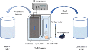
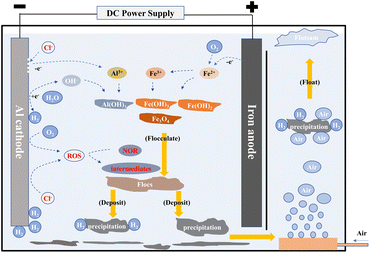
The schematic diagram of the AL-EC reactor used for this study is shown in Fig. 1. The device was constructed by the acrylic board with a size of 16 × 6 × 16.5 cm and a working volume of 1000 mL. It also included air pump, gas flowmeter, and bubble diffuser. Three pieces of metal plate electrodes (iron or aluminum) were vertically arranged in the cell. One anode was placed between the two cathodes to ensure that the current and potential on the anode distributes uniformly. The electrode size was 8 × 10.5 × 0.3 cm, the distance between the electrodes was set to 1 cm, and the effective electrodes area was about 150 cm2. The electrodes were connected in monopolar parallel mode with a DC power supply unit (MS-155D). The electrodes were polished with sandpaper and rinsed with 1% HCl solution and distilled water for removing oxides film before every run.The pH of synthetic solutions were measured by pH meter (Sanxin WS100) and adjusted to set values by 0.1 mol L−1 HCl or NaOH diluted solution. The valve of the air flow meter was set to the desired flow rate (when the air flow rate is set to 0 mL min−1, it is not aerated). When the steady state attained after few minutes, the power supply was turned on at the required settings of voltage/current. Samples were taken regularly (every 4 minutes) from the reactor and filtered through 0.45 μm micron filters before analysis. Dissolved oxygen concentrations were measured by multi-parameter water quality analyzer (HQ30d, HACH) with dissolved oxygen electrode (LDO10101, HACH). Electrodes were weighted before and after the treatment process. Sludge was dried at in a vacuum drying oven (YLD-2000) until constant weight and collected for further analysis.
2.3 Analysis
NOR concentration was determined at wavelength of 277 nm with ultraviolet and visible spectrophotometer (DR6000, HACH).The removal efficiency of NOR was calculated by the following eqn (1):
 | (1) |
The current density j (mA cm−2) was calculated according to the following eqn (2):
 | (2) |
During the electrocoagulation process, the amount of dissolved electrode (anode) can be described by Faraday's Law of Electrolysis:
 | (3) |
![[thin space (1/6-em)]](https://www.rsc.org/images/entities/char_2009.gif) 485 C mol−1).
485 C mol−1).
The energy consumption of electrodes during the EC process was calculated using the following eqn (4):
 | (4) |
The amount of sludge generated during the EC process was evaluated by sludge produced per NOR removed as g mg−1, calculated using the following eqn (5):
 | (5) |
A scanning electron micrograph-energy dispersive spectrometry (SEM) and X-ray fluorescence (XRF) (FEI Quanta 650, Thermo Fisher, U.S.A.) was used to characterize the morphology and mineralogical composition of flocs before and after aeration. The surface chemical functional groups of the flocs were performed using Fourier transform infrared spectroscopy (FT-IR) (Thermo Scientific Nicolet Summit, USA). X-ray diffraction (XRD) (D8 Advance, Bruker, Germany) was used to analyse the flocs' crystal structure. High-performance liquid chromatography-mass spectrometry (LC-MS) (Shimadzu, LCMS-9030, Japan) was used to identify the degradation intermediates of NOR.
3 Effect of operating parameters
3.1 Effect of electrode combinations
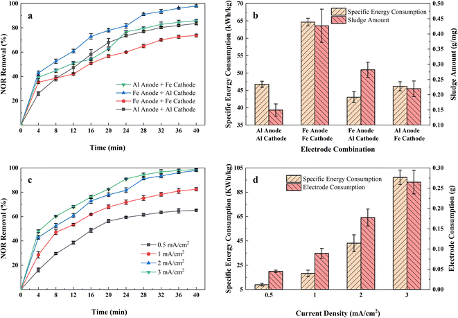
Fig. 2(a) shows the NOR removal performance of different electrode combinations at the same current densities (2 mA cm−2) at initial pH 7. It can be seen that the Fe anode and Al cathode combination had the highest NOR removal efficiency, reaching 93.48% after 32 minutes of treatment, while the Al anode and Fe cathode, Al anode and Al cathode, and Fe anode and Fe cathode combination were 82.84%, 80.31%, 70.13%, respectively.The specific energy consumption and sludge amount of different electrode combinations were shown in the Fig. 2(b). Maximum specific energy consumption was observed to be 64.65 kW h kg−1 with Fe anode and Fe cathode combination electrode combination after 40 minutes of treatment. It also formed the most sludge, up to 0.42 g mg−1. Fig. 2(b) also shows that all Fe anode combinations produced more sludge than aluminium anodes. Iron is less conductive than aluminium, so it requires a higher voltage at the same current density,23 led to Fe electrode combinations consumed more energy than Al electrode.
According to Faraday's law, the amount of coagulant metal dissolved is inversely proportional to the number of electrons lost and directly proportional to the molar mass of the metal. Fe loses fewer electrons in the reaction, and its molar mass is twice that of aluminium. Thus, Fe electrodes formed more coagulant to absorb pollutants and also produced more sludge. The formation of a tight layer of Al2O3 during the process limited the dissolution of the Al anode combinations,24 resulting in a low level of removal efficiency and low sludge yield. It also observed that denser bubbles formed on the Al cathode surface through the Fe anode and Al cathode combination. It is reported that smaller bubbles can promote the combination of the metal flocs and the pollutants, improving the removal efficiency.25
Therefore, considering the balance of power consumption, NOR removal efficiency, and sludge production, Fe anode and Al cathode were considered the best combination for further research.
3.2 Effect of current density
Applied current density refers to the ratio of applied current and electrode area. It is one of the most significant parameters affecting the EC process, for it determined the amount of metal dissolved in solutions and hence affected the formation of coagulants. Fig. 2(c) revealed the NOR removal rate in the airlift-electrocoagulation reactor with time at different current densities (in the range of 0.5–3 mA cm−2). The results showed that the NOR removal rate increased with the current density when raising current density from 0.5 to 3 mA cm−2 improved the removal efficiency from 65.08% to 98.68%.According to Faraday's Law, more metals and hydroxyl will be produced applying a higher current to form coagulants and remove pollutants.26 It would also generate more H2 bubbles from the cathode that capture pollutants, improving solution mixing and mass transfer near the electrode.27 More active species would also generate from the anode that accelerates chemical oxidation reaction, but some researchers noted that would lead to an increase in by-products and higher environmental risks.28,29 If the applied current is too high, it may lead to electrode passivation and increased polarization,30 leading to an increase in power consumption.31
Removal rates increased rapidly for the first 20 minutes at all different current densities. However, the continued application of current did not result in a more significant increase in removal efficiency, and additional energy and electrode materials were consumed. Fig. 2(d) displays the calculated quantity of iron electrode consumed (g) and energy consumption for 40 minutes of treatment at different current densities. It demonstrated that specific energy consumption increased vertically from 8.90 to 97.22 kW h kg−1 when the current density increased from 0.5 to 3 mA cm−2, and the dissolved iron electrode consumed from 0.045 to 0.265 g. Considering the balance between removal efficiency, electrode consumption, and energy consumption, a current density of 2 mA cm−2 was used in subsequent experiments.
3.3 Effect of solution pH
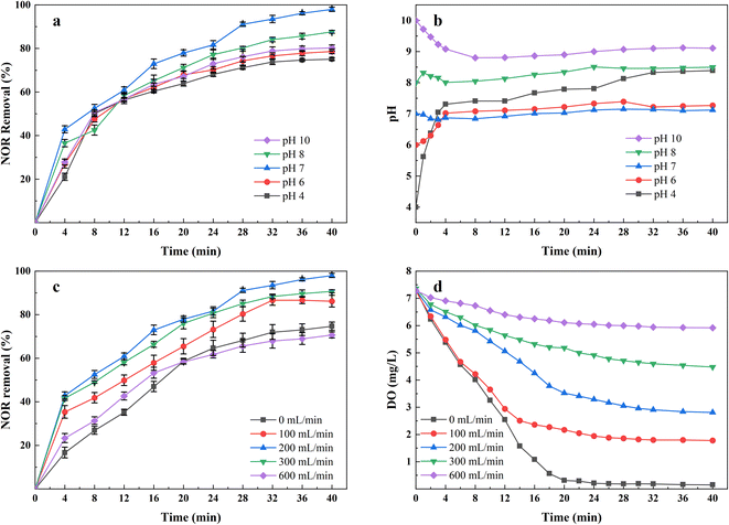
The solution pH is considered one of the critical parameters affecting the performance of the EC process, mainly affecting the speciation of coagulating agents and pollutants. The NOR removal rates and the values of pH changes in the solution are shown in Fig. 3. The results showed that the most favorable pH value for NOR removal was between 7 and 8, consistent with other researches,32,33 the electrocoagulation using iron anodes performed better in neutral and slightly alkaline conditions.At a low pH, soluble Fe2+ and Fe3+ were dominant in the solution.34 At the same time, in acid conditions, the rate of Fe2+ oxidation to Fe3+ was lower than that in neutral and alkaline conditions,35 forming less insoluble Fe(OH)3(S)/FeOOH(S) coagulants and therefore, NOR removal decreases. Additionally, At pH above 8, more iron hydroxide complexes like Fe(OH)4− (ref. 36) and Fe(OH)63− (ref. 37) formed by continuously consuming OH−, which explained why the solution pH decreased during the initial 5 minutes treatment at pH = 10, in Fig. 3(b). But these ions are useless to the treatment since their poor coagulation performance. Hydroxide ions would be oxidized at the anode and reduced anode dissolution at a high pH range, also decreasing removal efficiency.38
Fig. 3(b) also indicates that the solution pH during the electrocoagulation process almost does not change when the initial pH is between 7 and 8. This may be concluded to the produced OH− has completely reacted with the iron and aluminium ions to form various complexes.39 As shown in Fig. 3(b), the pH of the solution rose rapidly within 5 minutes under acidic conditions, that's because the electrocoagulation reactor was capable of producing enough OH− ions that compensate the acid-buffer and make the solution alkaline.
Therefore, all subsequent tests were conducted under the condition of neutral pH.
3.4 Effect of air flow rate
To evaluate the effect of the air flow rate on NOR removal efficiency, the experiments were investigated by varying air flow rate from 0 to 600 mL min−1, while keeping other operation parameters constant (pH = 7, initial NOR concentration 10 mg L−1, current density 2 mA cm−2). As shown in Fig. 3(c), the highest NOR removal efficiencies were found to be 97.97% with air flow rate of 200 mL min−1, and then 90.68% with air flow rate of 300 mL min−1, 86.15% with air flow rate of 100 mL min−1, 74.67% with air flow rate of 0 mL min−1. However, the removal efficiency dropped to 70.66% when applying 600 mL min−1 air flow rate. In addition, the colour of solutions changed from deep green to reddish brown when air flow rate changed from 0 mL min−1 to 600 mL min−1. The dissolved oxygen concentration with treatment time at each aeration rate was measured and shown in Fig. 3(d).Properly increased air flow rate can significantly enhance NOR removal efficiency. The air flow raising up, formed turbulence, which improved the mixing condition of the solutions, increased the collision probability between the pollutants and flocs,40 and made the pollutants captured more effectively. Also, the turbulence reduced the passivation layer on the electrodes, thereby enhancing the transport of ions between the electrodes. Meanwhile, during the EC process, the metal-hydroxide flocs formed at electrode surfaces,36 and the released gases accumulated at the electrode surface, increased the electrical resistance between the electrodes,41 leading to bad performance and extra energy consumption. The air flow increased the flow velocity to enhance hydrodynamic scouring,42 and the effect of air bubbles and deposits was reduced. As shown in Fig. 3(d), different air flow rate affected the dissolved oxygen concentration in solutions, which influenced the redox potential of solutions and, therefore the ratio of Fe2+/Fe3+ in the solutions. Higher dissolved oxygen levels helped Fe2+ oxidize rapidly to Fe3+, consistent with the observation of solution colour change. The capacity for forming hydrates is stronger for Fe3+, it further reacts with OH− to form Fe(OH)3 floc with a large surface area,20 absorbing more pollutant molecules. At the same time, a higher air flow rate can also promote the production of some reactive oxygen species, accelerate the decomposition of pollutants, and improve efficiency.
The decrease of removal rate in the case of high air flow could be attributed to excessive aeration breaking up the formed flocs,43 which pollutants absorbed in the EC process were released to solutions. It also led to an increase in suspended solids concentration. In the case of low or no air flow rate, the limited oxidation rate of Fe3+ ions may result in bad NOR removal efficiency.
3.5 Effect of supporting electrolyte types
The addition of supporting electrolyte in the electrocoagulation process to increase the conductivity of the solution to reduce ohmic drop, so as to reduce power consumption and improve efficiency. Therefore, Na2SO4, NaCl, and KCl were used as supporting electrolytes in the experiments to investigate the effect of supporting electrolyte type on the removal efficiency and energy consumption, and results were shown in Fig. 4(a). The quantity of adding NaCl, Na2SO4, and KCl was 0.5, 1.215, and 0.6378 g L−1, corresponding to 17.11 mM of ions.It showed the performances of the electrolyte species at 2 mA cm−2 current density, and it can be seen that the removal rate is higher for NaCl and KCl than that for Na2SO4, achieved 97.97%, 89.56%, and 80.34%, separately. The better performance for NaCl and KCl was attributed to the Cl− formed active chlorine species, they can participate in the oxidation of organic pollutants and ferrous ions.44 A report showed that a high concentration of Na2SO4 would react with iron hydroxides, decrease the amount of coagulant,45 and reduced the removal efficiency. In addition, the conductivity of NaCl and KCl was higher than that of Na2SO4 at the same ions intensity, and the required voltage will be much lower,46 which explained using Na2SO4 as supporting electrolyte consumed more energy in Fig. 4(b).
Although adding the Cl− can prompt the oxidation capacity, the degradation by-products could be more toxic than the parent pollutants.47 Moreover, excessive Cl− may accelerate the corrosion pitting rate that leads to overconsumption of Fe48 and Al49 electrodes. We need to control the amount of electrolyte added to the solution, which is limited to 0.5 g L−1 of NaCl in this study.
3.6 Effect of initial concentration
Different initial concentrations of NOR from 10 to 100 mg L−1 were selected for the experiment, and the current density was 2 mA cm−2. As shown in Fig. 5, the ratio of sludge produced to NOR removed increased from 0.28 to 0.42 g mg−1. Higher initial concentration results in greater NOR removal. However, the residual NOR concentration increased from 0.20 to 2.53 mg L−1 when NOR concentration was increased from 10 to 100 mg L−1. Residual NOR cannot be removed further and remains at a high concentration.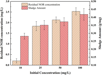 | ||
| Fig. 5 Influence of different initial concentration on NOR removal; electrode combination, Fe anode and Al cathode, current density = 2 mA cm−2, initial pH = 7, air flow rate = 200 mL min−1. | ||
It was due to the same amount of iron hydroxide complexes were generated at the same treatment time and current density, the coagulants formed at high NOR concentration were insufficient to adsorb all of the NOR molecules of the solution. Another explanation for removal efficiency decreasing is probably due to the metal hydroxide flocs that trap pollutants molecules lack active sites.50 For solutions with high initial pollutants concentrations, could achieve better removal efficiencies by diluting solutions.51
4 Mechanism of NOR removal in AL-EC reactor
4.1 Characterization of flocs
Flocs generated from the process under the aeration and non-aeration condition using an AL-EC reactor were characterized by SEM-XRF, FTIR, and XRD.The morphological characteristics and its elements content are presented in Fig. 6. The morphologies of the flocs under 500![[thin space (1/6-em)]](https://www.rsc.org/images/entities/char_2009.gif) 00× and 1
00× and 1![[thin space (1/6-em)]](https://www.rsc.org/images/entities/char_2009.gif) 000
000![[thin space (1/6-em)]](https://www.rsc.org/images/entities/char_2009.gif) 00× magnification are shown in Fig. 6(a)–(d) with the consistency of regular particles. As shown in Fig. 6(a) and (b), the flocs formed under aeration conditions had a rough and porous surface, loose structure, and large surface area, which is beneficial to the adsorption of NOR. Under the non-aeration condition, the floc surface was relatively flat and lacked a porous and loose structure (Fig. 6 (c) and (d)).
00× magnification are shown in Fig. 6(a)–(d) with the consistency of regular particles. As shown in Fig. 6(a) and (b), the flocs formed under aeration conditions had a rough and porous surface, loose structure, and large surface area, which is beneficial to the adsorption of NOR. Under the non-aeration condition, the floc surface was relatively flat and lacked a porous and loose structure (Fig. 6 (c) and (d)).
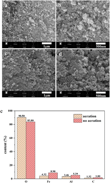 | ||
| Fig. 6 SEM and XRF analysis of flocs generated from EC treatment by AL-EC reactor in aerated and non-aerated condition for NOR removal. | ||
The XRF (Fig. 6(e)) revealed the component elements and content in the flocs, the main constituent elements were O, Fe, Al, C. The flocs produced under aeration had a higher O content and lower Fe content, with 90.50% and 4.31% compared to 83.80% and 8.90%, it indicated that aeration enhanced the oxidation of flocs and produced more iron oxides. At the same time, the contents of Al in aerated and non-aerated flocs were 3.46% and 5.29%, respectively. This can be explained that the chloride ions added in the solution caused pitting corrosion of the electrode, and part of the Al in the cathode was also dissolved in the solution, according to the previous research results.52 Iron and aluminium ions formed a series of mono or multi-core metal hydroxyl complexes in the reactor and removed NOR.
As seen in Fig. 7(a), the peak shapes of FTIR for aerated and non-aerated flocs were very similar, with five characteristic peaks. The strong and wide absorption bands near 3437 cm−1 are attributed to the stretching vibration of –OH and water molecules,53 indicating the existence of hydroxide and water molecules in the flocs. The characteristic peak at 560 cm−1 corresponds to Fe–O bond,54 and it can be inferred that both aerated and non-aerated flocs contain iron oxide compounds. From 1300 to 1670 cm−1, both flocs and NOR showed resemble peak shapes, peaks appeared at 1633, 1489, 1382 cm−1, corresponding to the characteristic peaks of C![[double bond, length as m-dash]](https://www.rsc.org/images/entities/char_e001.gif) O, aromatic C
O, aromatic C![[double bond, length as m-dash]](https://www.rsc.org/images/entities/char_e001.gif) C bond55 and –COO− group,56 respectively. It indicated the formation of interaction between NOR's functional groups and flocs. From the FTIR results, it can be inferred that during in EC process formed flocs composed of iron hydroxide, and bonded to the NOR's functional groups on the surface. The NOR was mainly removed through complexation and physical adsorption, then precipitated together with flocs.
C bond55 and –COO− group,56 respectively. It indicated the formation of interaction between NOR's functional groups and flocs. From the FTIR results, it can be inferred that during in EC process formed flocs composed of iron hydroxide, and bonded to the NOR's functional groups on the surface. The NOR was mainly removed through complexation and physical adsorption, then precipitated together with flocs.
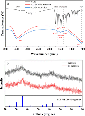 | ||
| Fig. 7 FTIR and XRD analysis of flocs generated from EC treatment by AL-EC reactor in aerated and non-aerated condition for NOR removal. | ||
The crystal structures of the two flocs are shown in Fig. 7(b). Both flocs showed broad peaks but no significant sharp characteristic diffraction peaks, it is indicated that flocs were amorphous structures. The formation of nano-sized metal particles and the high hydration of metal hydroxide floc can explain the poor crystallization.57 In both aerated and non-aerated conditions, flocs eventually converted into magnetite (Fe3O4), which can be formed by the following reactions (eqn (6) and (7)):58,59
| 3Fe(OH)3(s) + H+ + e− → Fe3O4(s) + 5H2O | (6) |
| 3Fe(OH)2(s) → Fe3O4(s) + H2(g) + 2H2O(l) | (7) |
Those iron hydroxides with richer hydroxyl function groups and larger specific surface areas formed in the EC process, which achieved the ability to absorb pollutants.
4.2 Possible degradation pathways of NOR
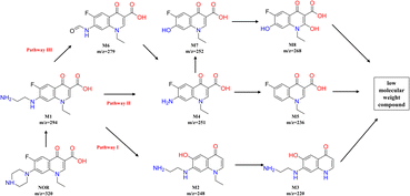
Under the condition of aeration and the existence of chlorine electrolyte, active substances such as ClO˙ and ˙OH can be produced, which can occur oxidation reactions with NOR and form some intermediates. The degradation intermediates in the treatment process were identified using the LC-MS. As seen in Fig S1,† different peaks appeared as the reaction progressed, indicating intermediate formation. Based on the literature review and comparative analysis of mass–charge ratio (m/z), eight intermediate products were determined, as shown in Table S1.†In general, NOR could be degraded through the substitution, hydroxylation, decarboxylation, and oxidation of the amino group of the piperazine ring in the following pathways (Fig. 8). Piperazine ring was first oxidized to open the ring,60 lost the –C2H2– group, and formed the intermittent product M1 (m/z = 294). Then in pathway I, it underwent decarboxylation and transformed to M2 (m/z = 248), M2 lost ethyl group61 and further oxidized to M3 (m/z = 220). In the Pathway II, M1 can be first converted into M4 (m/z = 251) and then further into M5 (m/z = 236) by losing amino group.62 Hydroxyl groups can also substitute the amino groups in the benzene ring of M4 to form M7 (m/z = 252), and M7 was further oxidized from M8 (m/z = 268). In addition, in pathway III, M4 can also generate from M6 (m/z = 236), which was formed by M1 and lost a C2H5N group.7 As the oxidation process continues, those intermediates can be further degraded to low molecular weight compounds.
4.3 Removal mechanism of NOR
Based on the above experiment investigation and analysis, the removal mechanism of NOR by AL-EC with iron and aluminium electrode were proposed and shown in Fig. 9.5 Application and cost evaluation
5.1 Efficiency of AL-EC reactor for different antibiotics and removal NOR in different types of water
In order to evaluate the performance of the AL-EC reactor in practical application, the treatment of different kinds of antibiotics and the influence of different water types on NOR removal were studied, as shown in Fig. 10.Antibiotics such as Tetracycline (TC)63,64 and Metronidazole (MNZ)65 were reported can be removed in other electrocoagulation systems by oxidation and adsorption process. Therefore, TC and MNZ were chosen as model pollutants and evaluated their removal efficiency. As shown in Fig. 9(a), all three antibiotics achieved a removal efficiency of over 80%. The highest was NOR, followed by TC and MNZ, which were 85.27% and 82.47%, separately. The above results showed that using the AL-EC reactor to remove varieties of antibiotics from wastewater can exhibit good performance.
These experiments were carried out in synthetic wastewater that dissolved antibiotics in deionized water. Compared to deionized water, groundwater, and river water consists of some extra ions such as chloride and carbonates that may compete with antibiotic molecules in solution, which decreases the removal efficiency. As seen in Fig. 9(b), when the solutions were replaced from deionized water with groundwater and river water, the removal efficiency of NOR dropped from 97.97% to 85.64% and 71.66%. Besides the adsorption competition during the NOR removal process, the lower efficiency may be due to the complexity of river water. But in the EC process, sufficient iron hydroxides were formed to absorb the contaminants and still remained above 70% removal efficiency.
The results above proved the high removal efficiency of the AL-EC reactor for different antibiotics and removal the NOR in different types of water, which means it had universality and adaptability in practical application.
5.2 Evaluation of operating cost of AL-EC
The operation cost of the water treatment process is one of the important factors to be considered in practical applications, so it is necessary to evaluate the operating cost.The operation cost is composed of three parts, the electric energy consumption of aeration and electrocoagulation, the material consumption of electrode, which was calculated by the following equation:
 | (8) |
![[thin space (1/6-em)]](https://www.rsc.org/images/entities/char_2009.gif) 485 C mol−1). In general, the cost evaluation was carried out according to the optimal conditions: current density 2 mA cm−2, initial pH 7, treatment time 32 minutes and air flow rate of 200 mL min−1 (Table 1).
485 C mol−1). In general, the cost evaluation was carried out according to the optimal conditions: current density 2 mA cm−2, initial pH 7, treatment time 32 minutes and air flow rate of 200 mL min−1 (Table 1).
| Anode types | Pollutant types | Current density (mA cm−2) | Electricity consumption (kW h m−3) | Operation costa (USD m−3) | References |
|---|---|---|---|---|---|
| a Operation cost includes electrical energy consumption and the cost of dissolved Fe anode. | |||||
| Fe | Metronidazole | 6 | 0.516 | \ | 65 |
| Al | Diclofenac | 1.8 | 6.91 | 1.57 | 66 |
| Stainless steel | Levofloxacin; ciprofloxacin | 20 | 3.211 | 0.613 | 67 |
| Fe | Tetracycline | 4 | 0.110 | 0.177 | 68 |
| Fe | Norfloxacin | 2 | 0.388 | 0.153 | This study |
6 Conclusions
In summary, the AL-EC reactor showed great potential for NOR removal from water, with low cost and high efficiency. The following optimal operating parameters were identified: iron anode and aluminum cathode combination, the current density of 2 mA cm−2, initial pH of 7, treatment time of 32 minutes and an air flow rate of 200 mL min−1, supporting electrolyte type was NaCl, initial NOR concentration of 10 mg L−1. The flocs were characterized using SEM, XRF, FT-IR, and XRD. Intermediate of NOR degradation was identified by LC-MS and proposed a possible degradation pathway during the electrocoagulation process. The results revealed that NOR removal mechanism was mainly due to electrochemical oxidation and floc adsorption. Using the optimal operating condition of the AL-EC reactor to treat the real water and different types of antibiotics, it was found that the minimum removal rate was over 60%, indicating its universality and adaptability. The operation cost under the optimum conditions was estimated at 0.153 USD m−3. This study shows that electrocoagulation combining airlift technology was an effective and cost-saving method for removing NOR or other antibiotic complexes from water. We hope that, by further optimizing the reactor design and operating parameters, the AL-EC technology can be applied for large-scale treatment of antibiotics or other organic wastewater.Author contributions
X. G Gu: conceptualization, methodology, software, data curation, writing – original draft preparation; X. T Feng, J. K, Wang and W. Y Qu: visualization, investigation; J. F Li: supervision, involved in conceptualization, methodology, software and english revising; W. Y Qu and W. H Wang: involved in software and validation.Conflicts of interest
The authors declare that they have no conflict of interest.Acknowledgements
Financial support from the National Natural Science Foundation of China (52260002, 42107414), the Special Application Science and Technology Project of the 7th Division in Xinjiang Bingtuan (2021A03008) and the Special Young Talented Research Project of Shihezi University (CXPY202201) are gratefully acknowledged.References
- A. Bielen, A. Šimatović, J. Kosić-Vukšić, I. Senta, M. Ahel, S. Babić, T. Jurina, J. J. González Plaza, M. Milaković and N. Udiković-Kolić, Water Res., 2017, 126, 79–87 CrossRef CAS PubMed.
- E. Szekeres, A. Baricz, C. M. Chiriac, A. Farkas, O. Opris, M.-L. Soran, A.-S. Andrei, K. Rudi, J. L. Balcázar, N. Dragos and C. Coman, Environ. Pollut., 2017, 225, 304–315 CrossRef CAS PubMed.
- X.-L. Zhao, P. Li, C. Qu, R. Lu and Z.-H. Li, Comp. Biochem. Physiol., Part C: Toxicol. Pharmacol., 2022, 258, 109365 CAS.
- P. T. P. Hoa, S. Managaki, N. Nakada, H. Takada, A. Shimizu, D. H. Anh, P. H. Viet and S. Suzuki, Sci. Total Environ., 2011, 409, 2894–2901 CrossRef CAS PubMed.
- J. Zhou and Q. Sun, Polymers, 2022, 14, 3984 CrossRef CAS PubMed.
- J. He, Y. Zhang, F. Ni, D. Tian, Y. Zhang, L. Long, Y. He, C. Chen and J. Zou, Sci. Total Environ., 2022, 831, 154826 CrossRef CAS PubMed.
- Z. Wang, B. Song, J. Li and X. Teng, Chemosphere, 2021, 270, 128652 CrossRef CAS PubMed.
- L. Miao, J. Li, L. Yi, W. Qu, C. Ma, X. Feng, Y. Xu and R. He, J. Clean. Prod., 2022, 378, 134421 CrossRef CAS.
- Y. Ma, Z. Wang, W. Yang, C. Chen, J. Li, R. He and S. Liu, J. Water Process Eng., 2022, 49, 103184 CrossRef.
- X. Ma, Y. Cheng, Y. Ge, H. Wu, Q. Li, N. Gao and J. Deng, Ultrason. Sonochem., 2018, 40, 763–772 CrossRef CAS PubMed.
- A. Shahedi, A. K. Darban, F. Taghipour and A. Jamshidi-Zanjani, Curr. Opin. Electrochem., 2020, 22, 154–169 CrossRef CAS.
- S. Y. Lee and G. A. Gagnon, Sep. Purif. Technol., 2016, 163, 162–168 CrossRef CAS.
- N. Farhadian, J. Behin and A. Parvareh, Comput. Fluids, 2018, 167, 221–228 CrossRef.
- S. H. Ammar and A. S. Akbar, Chin. J. Chem. Eng., 2018, 26, 879–885 CrossRef CAS.
- J. Behin, N. Farhadian, M. Ahmadi and M. Parvizi, J. Water Process Eng., 2015, 8, 171–178 CrossRef.
- N. Chawaloesphonsiya, C. Prommajun, K. Wongwailikhit and P. Painmanakul, Environ. Technol., 2017, 38, 1295–1304 CrossRef CAS PubMed.
- M. Bennajah, B. Gourich, A. H. Essadki, C. Vial and H. Delmas, Chem. Eng. J., 2009, 148, 122–131 CrossRef CAS.
- H. K. Hansen, P. Nuñez and C. Jil, Sep. Sci. Technol., 2008, 43, 212–224 CrossRef CAS.
- R. Elkacmi, O. Boudouch, A. Hasib, M. Bouzaid and M. Bennajah, Sustain. Chem. Pharm., 2020, 17, 100274 CrossRef.
- N. Nippatla and L. Philip, J. Environ. Manage., 2020, 273, 111039 CrossRef CAS PubMed.
- A. Y. Goren, M. Kobya and M. S. Oncel, Chemosphere, 2020, 251, 126363 CrossRef CAS PubMed.
- D. Balarak, M. Dashtizadeh, R. S. Oguike and K. Chandrika, J. Pharm. Res. Int., 2020, 32, 53–60 CrossRef.
- M. Chafi, B. Gourich, A. H. Essadki, C. Vial and A. Fabregat, Desalination, 2011, 281, 285–292 CrossRef CAS.
- M. Mechelhoff, G. H. Kelsall and N. J. D. Graham, Chem. Eng. Sci., 2013, 95, 301–312 CrossRef CAS.
- N. N. Abdulrazzaq, B. H. Al-Sabbagh and H. A. Shanshool, J. Water Process Eng., 2021, 40, 101906 CrossRef.
- N. Galvão, J. B. de Souza and C. M. d. S. Vidal, J. Environ. Chem. Eng., 2020, 8, 104368 CrossRef.
- M. H. Abdel-Aziz, E. S. Z. El-Ashtoukhy, M. S. Zoromba, M. Bassyouni and G. H. Sedahmed, J. Ind. Eng. Chem., 2020, 82, 105–112 CrossRef CAS.
- B. Xu, S. M. Iskander and Z. He, Environ. Res., 2020, 182, 109006 CrossRef CAS PubMed.
- L. Bilińska, K. Blus, M. Foszpańczyk, M. Gmurek and S. Ledakowicz, J. Environ. Manage., 2020, 265, 110502 CrossRef PubMed.
- S. Fu, H. Jia, X. Meng, Z. Guo and J. Wang, Sci. Total Environ., 2021, 781, 146797 CrossRef CAS.
- M. H. Ibrahim, D. T. Moussa, M. H. El-Naas and M. S. Nasser, J. Water Process Eng., 2020, 33, 101091 CrossRef.
- R.-F. Chen, L. Wu, H.-T. Zhong, C.-X. Liu, W. Qiao and C.-H. Wei, Sep. Purif. Technol., 2021, 272, 118900 CrossRef CAS.
- N. Huda, A. A. A. Raman, M. M. Bello and S. Ramesh, J. Environ. Manage., 2017, 204, 75–81 CrossRef CAS PubMed.
- C. M. van Genuchten, T. Behrends, P. Kraal, S. L. S. Stipp and K. Dideriksen, Electrochim. Acta, 2018, 286, 324–338 CrossRef CAS.
- F. Akbal and S. Camcı, Desalination, 2011, 269, 214–222 CrossRef CAS.
- M. Kobya, U. Gebologlu, F. Ulu, S. Oncel and E. Demirbas, Electrochim. Acta, 2011, 56, 5060–5070 CrossRef CAS.
- B. Yang, Y. Han, Y. Deng, Y. Li, Q. Zhuo and J. Wu, Emerg. Contam., 2016, 2, 49–55 CrossRef.
- M. Nasrullah, L. Singh, S. Krishnan, M. Sakinah, D. M. Mahapatra and A. W. Zularisam, J. Water Process Eng., 2020, 33, 101114 CrossRef.
- H. Huang, D. Zhang, Z. Zhao, P. Zhang and F. Gao, J. Clean. Prod., 2017, 141, 429–438 CrossRef CAS.
- P. Song, Z. Yang, H. Xu, J. Huang, X. Yang and L. Wang, Ind. Eng. Chem. Res., 2014, 53, 12911–12919 CrossRef CAS.
- N. Muhammad Niza, M. S. Yusoff, M. A. A. Mohd Zainuri, M. I. Emmanuel, A. Mohamed Hussen Shadi and M. A. Kamaruddin, J. Water Process Eng., 2020, 36, 101282 CrossRef.
- M. Ingelsson, N. Yasri and E. P. L. Roberts, Water Res., 2020, 187, 116433 CrossRef CAS PubMed.
- L. Q. Xu, X. J. Xu, G. Z. Cao, S. L. Liu, Z. Y. Duan, S. M. Song, M. Y. Song and M. J. Zhang, J. Environ. Manage., 2018, 218, 129–138 CrossRef CAS PubMed.
- Z. Guo, Y. Zhang, H. Jia, J. Guo, X. Meng and J. Wang, Sci. Total Environ., 2022, 806, 150529 CrossRef CAS PubMed.
- W. T. Mook, M. K. Aroua, M. Szlachta and C. S. Lee, Water Sci. Technol., 2016, 75, 952–962 CrossRef PubMed.
- C. J. Izquierdo, P. Canizares, M. A. Rodrigo, J. P. Leclerc, G. Valentin and F. Lapicque, Desalination, 2010, 255, 15–20 CrossRef CAS.
- E. A. Serna-Galvis, K. E. Berrio-Perlaza and R. A. Torres-Palma, Environ. Sci. Pollut. Res., 2017, 24, 23771–23782 CrossRef CAS PubMed.
- M.-K. Kim, T. Kim, T.-K. Kim, S.-W. Joo and K.-D. Zoh, Sep. Purif. Technol., 2020, 247, 116911 CrossRef CAS.
- J. R. Silva, F. Carvalho, C. Vicente, A. D. Santos, R. M. Quinta-Ferreira and L. M. Castro, J. Environ. Chem. Eng., 2022, 10, 107750 CrossRef CAS.
- A. Oulebsir, T. Chaabane, H. Tounsi, K. Omine, V. Sivasankar, A. Flilissa and A. Darchen, J. Environ. Chem. Eng., 2020, 8, 104597 CrossRef CAS.
- M. Reilly, A. P. Cooley, B. Richardson, D. Tito and M. K. Theodorou, J. Water Process Eng., 2021, 42, 102121 CrossRef.
- M. A. Sandoval, R. Fuentes, A. Thiam and R. Salazar, Sci. Total Environ., 2021, 753, 142108 CrossRef CAS PubMed.
- X. Lü, T. Xu, Y. Zhou, Q. Peng, J. Ou, B. Hu, Z. Xie, X. Lei and G. Yu, J. Environ. Sci., 2023, 124, 823–834 CrossRef PubMed.
- Y. Zhong, C. Chen, S. Liu, C. Lu, D. Liu, Y. Pan, H. Sakiyama, M. Muddassir and J. Liu, Dalton Trans., 2021, 50, 18016–18026 RSC.
- Y. Wang, W. Yu, Z. Chang, C. Gao, Y. Yang, B. Zhang, Y. Wang and B. Xing, Sci. Total Environ., 2022, 848, 157495 CrossRef CAS PubMed.
- L. Zhao, J. Liu, H. Wang and Y.-h. Dong, Environ. Sci. Pollut. Res., 2019, 26, 10685–10694 CrossRef CAS PubMed.
- P. Oulego, M. A. Villa-García, A. Laca and M. Diaz, Dalton Trans., 2016, 45, 9446–9459 RSC.
- K. K. Aligizaki, M. R. de Rooij and D. D. Macdonald, Cem. Concr. Res., 2000, 30, 1941–1945 CrossRef CAS.
- K. Govindan, A. Angelin, M. Kalpana, M. Rangarajan, P. Shankar and A. Jang, ACS Appl. Mater. Interfaces, 2020, 12, 1775–1788 CrossRef CAS PubMed.
- L. Yi, B. Li, Y. Sun, S. Li, Q. Qi, J. Qin, H. Sun, X. Wang, J. Wang and D. Fang, Sep. Purif. Technol., 2021, 259, 118166 CrossRef CAS.
- X. Chen, R. Zhuan and J. Wang, J. Hazard. Mater., 2021, 404, 124172 CrossRef CAS PubMed.
- F. Zhu, Y. Wu, Y. Liang, H. Li and W. Liang, Chem. Eng. J., 2020, 389, 124276 CrossRef CAS.
- H. Zhang, J. M. Bian, C. G. Yang, Z. C. Hu, F. Y. Liu and C. P. Zhang, Sci. Total Environ., 2022, 810, 151955 CrossRef CAS PubMed.
- Y. H. Zhou, B. N. Hu, X. J. Zhuang, J. X. Qiu, T. Xu, M. P. Zeng, X. He and G. Yu, Sustainability, 2022, 14, 2328 CrossRef CAS.
- R. Zhou, F. Y. Liu, X. Y. Du, C. P. Zhang, C. G. Yang, N. A. Offiong, Y. H. Bi, W. Zeng and H. J. Ren, Sep. Purif. Technol., 2022, 290, 120799 CrossRef CAS.
- B. M. B. Ensano, L. Borea, V. Naddeo, V. Belgiorno, M. D. G. de Luna, M. Balakrishnan and F. C. Ballesteros, J. Hazard. Mater., 2019, 361, 367–373 CrossRef CAS PubMed.
- S. J. Mohammed, M. J. M-Ridha, K. M. Abed and A. A. M. Elgharbawy, Int. J. Environ. Anal. Chem., 2021, 1–19, DOI:10.1080/03067319.2021.1913733.
- S. Ahmadzadeh and M. Dolatabadi, Chemosphere, 2018, 212, 533–539 CrossRef CAS PubMed.
Footnote |
| † Electronic supplementary information (ESI) available. See DOI: https://doi.org/10.1039/d3ra00471f |
| This journal is © The Royal Society of Chemistry 2023 |

