
 Open Access Article
 This Open Access Article is licensed under a Creative Commons Attribution-Non Commercial 3.0 Unported Licence
Solvothermal synthesis of hair-like carbon nanotubes onto sub-micron-sized spherical metal oxide catalyst cores†
Kazuya Kobiro *ab,
Hinako Kimuraa,
Saki Hirosea,
Makoto Kinjoa and
Hiroshi Furuta*ac
*ab,
Hinako Kimuraa,
Saki Hirosea,
Makoto Kinjoa and
Hiroshi Furuta*ac
aGraduate School of Engineering, Kochi University of Technology, 185 Miyanokuchi, Tosayamada, Kochi 782-8502, Japan. E-mail: kobiro.kazuya@kochi-tech.ac.jp; furuta.hiroshi@kochi-tech.ac.jp
bCenter for Structural Nanochemistry, Research Institute, Kochi University of Technology, 185 Miyanokuchi, Tosayamada, Kochi 782-8502, Japan
cCenter for Nanotechnology, Research Institute, Kochi University of Technology, 185 Miyanokuchi, Tosayamada, Kochi 782-8502, Japan
First published on 5th May 2023
Abstract
Long- and uniform-length, and high-density hair-like carbon nanotubes (CNTs) were produced by CNT growth on sub-micron-sized spherical catalyst supports. The nanosized catalysts (FeOx, CoOx, and NiOx) that were supported in/on the sub-micron-sized spherical metal oxides (TiO2, ZrO2, SnO2, and CeO2) were prepared via one-step solvothermal and/or two-step impregnation methods. The nanosized catalysts supported in/on the spherical metal oxide supports were converted into CNT conjugates with the CNT-hair morphology via a chemical thermal vapor deposition technique using ethyne gas as a carbon source; the CNTs grew on the central spherical metal oxide core under the base growth process conditions. Among the many types of candidate spherical catalyst materials, the combination of FeOx as a catalyst for CNT growth and ZrO2 as a support led to the best growth of CNT-hair under the reaction conditions, which included a temperature of 730 °C, pressure of 65 Pa, a 10 sccm ethyne gas flow, and a reaction time of 10 s. The CNTs consisted of five-to-eight-layered multi-wall structures with lengths of approximately 3 μm. The CNT-hair that was obtained using the solvothermally embedded catalyst showed higher crystallinity and was dense, thick, and straight, while the corresponding CNT-hair obtained using the impregnated catalyst was slightly sparse, thin, and curly. A unique layer structure constructed using large quantities of uniform CNT-hair, including multiple CNT yarns similar to fuzzy balls or cotton candies, was assembled. The CNT-hair conjugate, specifically constructed in a layer structure with core FeOx/ZrO2 catalysts and tangled CNT yarns, had an appearance similar to frog eggs. Therefore, we successfully prepared suitable catalysts for CNT-hair production and fabricated a layer structure consisting of large numbers of CNT-hair conjugates. The unique structures are expected as a new metamaterial with intriguing physical properties, including isotropic absorption of polarized light and electromagnetic waves.
Introduction
Carbon nanotubes (CNTs) have attracted researchers' interest because of their unique electrical, thermal, and mechanical properties since they were first reported by Iijima.1 A wide variety of CNT-based applications have been reported that use their specific properties in transistors, chemical sensors, thermal absorbers, composites with carbon nanotubes, loudspeakers, and wires for space-elevators. Both quality control and mass production of these CNTs are desired for further development of future applications based on CNTs.Commercially available CNTs such as HiPCo and CoMoCAT are produced via gas-phase synthesis using catalytic thermal chemical vapor deposition (CVD). In these processes, residual metal catalysts remain in the bodies of the nanotubes, which can cause their electrical, thermal, and mechanical properties to degrade. A relatively new method to accomplish high-purity fabrication of CNTs was investigated using catalytic thermal CVD on substrates, by which CNTs are grown with high-area density and uniform lengths on catalysts on the substrates. High-quality CNTs with low amounts of residual catalytic metals in the CNT bodies are expected to be produced by the catalytic thermal CVD process on the substrates.
Increasing the mass of CNT production in a single batch during high-quality thermal CVD growth on flat substrates is still challenging. Noda et al. reported higher mass production of CNTs on 0.1 mm-sized Al2O3 beads using a thermal CVD process that combined a fluidized-bed method with catalytic thermal CVD by increasing the surface area of the substrates.2,3 Verpillere et al. reported the smallest diameter for the spherical substrate to increase the surface area of the substrates,4 but the uniformity of the diameter of the spherical substrate was not investigated.
Vertically aligned high-areal density CNT films were grown on substrates to a uniform length to produce so-called CNT forests, which opened up a wide variety of new applications for CNTs in the electrical, mechanical, and optical fields, including field emitters, electrode structures for secondary batteries, and metamaterials. We have previously reported uniform and high-density growth of CNT forests using thin film metal catalysts followed by thermal CVD using carbon gas sources. The height of the CNTs was controlled from an optical wavelength scale of <1 μm to a mechanical scale of 250 μm in length via pulse gas source control using an automated gas bulb.5,6 Optical metamaterial features including resonance absorption effects were observed successfully when using these high-density CNT films.
In addition, many spherical core catalysts for CNT growth applications have been reported to date. For example, He et al. reported diameter- and length-dependent self-organization of CNTs on micro-spherical alumina particles with sizes of 3–10 μm.7 Park et al. prepared sea urchin-like CNT conjugates using a combination of spray pyrolysis and thermal CVD in the gas phase.8 Piao et al. prepared sea urchin-shaped CNTs using hollow carbon spheres that contained iron oxide on their surfaces.9 Kim et al. reported a semi-continuous fluidized-bed process that yielded CNT using approximately 500 μm-sized alumina beads as cores.10 Jo et al. investigated continuous-flow synthesis of carbon-coated silicon/iron silicide particles.11 In addition, Boi et al. developed radial ferromagnetically filled-CNT structures.12 Chen et al. reported sea urchin-like CNT/polyhedra structures starting from a zeolitic imidazolate framework (ZIF).13 Boron nitrate was also used as a core material to yield CNT conjugates.14 However, it is still difficult to accomplish homogeneous growth of dense CNTs with a uniform length from sub-micron-sized spherical core catalysts, because (i) core spherical catalysts larger than 1 μm in size are commercially available, but their sub-micron-sized counterparts are not easy to obtain; (ii) the availability of practical preparation techniques that can yield a variety of porous metal oxide cores with almost perfect spherical morphologies and sub-micron sizes is also limited; and (iii) the uniformity of the catalyst films on the catalyst supports is a specific feature of the magnetron sputtering method for planar substrates.
As an alternative, we have studied a unique and simple synthesis method to obtain sub-micron-sized spherical porous assemblies consisting of metal oxide nanoparticles using one-pot and single-step solvothermal reactions.15 For example, MgO,16 TiO2,17 ZrO2,18,19 Nb2O5,20 SnO2,21 and CeO2 (ref. 22) assemblies were prepared successfully using this process. The assemblies obtained have almost perfect spherical morphologies with huge specific surface areas. We called these structures meso-/micro-porously architected roundly integrated metal oxide (MARIMO) particles.15 Composite MARIMOs, including several metal oxides, were synthesized easily using the solvothermal method, including Al2O3/TiO2,23 SiO2/TiO2,24 Nb2O5/TiO2,25 SiO2/ZrO2,26 ZrO2/CeO2,27 POx/SnO2,21 and CoOx/MnOy particles.28 Industrial scale synthesis of some of these materials is also possible.29 The MARIMOs obtained have characteristic nano-concave–convex surface structures and large numbers of pores that can capture noble metal nanoparticles effectively, leading them to support nanometal catalysts. Nanometal catalysts supported on MARIMOs such as Au/MARIMO TiO2 for use in CO oxidation30 and Ni/MARIMO ZrO2 for dry reforming of methane19,26 were easy to prepare and exhibited high performance and durability when used in these reactions. Therefore, we speculated that our sub-micron-sized spherical catalysts would yield well-defined sea urchin-like CNT conjugates with uniform growth of CNTs if we used them as catalysts for CNT growth.
In this paper, preparation of spherical core catalysts suitable for CNT growth using the solvothermal method, detailed reaction conditions for production of CNT-MARIMO conjugates, and characterization of the conjugates obtained are discussed.
Experimental details
Materials
85% zirconium(IV) butoxide (Zr(OnBu)4) in 1-butanol, iron(III) nitrate nonahydrate (Fe(NO3)3·9H2O), cobalt(II) nitrate hexahydrate (Co(NO3)2·6H2O), nickel(II) nitrate hexahydrate (Ni(NO3)2·6H2O), zirconium dioxide (ZrO2), cerium(III) nitrate hexahydrate (Ce(NO3)3·6H2O), benzoic acid, diethylene glycol, acetonitrile, and methanol were purchased from FUJIFILM Wako Pure Chemical Corporation. Acetylacetone was obtained from Tokyo Chemical Industry Co., Ltd. Ethanol was purchased from Kishida Chemical Co., Ltd. UEP-100 ZrO2 nanoparticles were obtained from Daiichi Kigenso Kagaku Kogyo Co., Ltd. All reagents were used as-received. TiO2,15,17 ZrO2,19 SnO2,21 and CeO2 (ref. 22) MARIMOs were prepared according to the previously reported procedure.Synthesis of catalysts for CNT formation
| Sample namea | Catalyst metal oxide | Atomic ratio of catalyst metal/support metal in precursor solution | Metal sources | Additive | Solvent |
|---|---|---|---|---|---|
| a s, the number, and M represent prepared by the solvothermal method, the atomic percentage of the catalyst metal element from the total amount of catalyst and support metal elements and MARIMO ZrO2, respectively. | |||||
| s5-FeOx/ZrO2-M | FeOx | 5/95 | Fe(NO3)3 + Zr(OnBu)4 | Acetylacetone | Ethanol |
| s10-FeOx/ZrO2-M | FeOx | 10/90 | Fe(NO3)3 + Zr(OnBu)4 | Acetylacetone | Ethanol |
| s20-FeOx/ZrO2-M | FeOx | 20/80 | Fe(NO3)3 + Zr(OnBu)4 | Acetylacetone | Ethanol |
| s30-FeOx/ZrO2-M | FeOx | 30/70 | Fe(NO3)3 + Zr(OnBu)4 | Acetylacetone | Ethanol |
| s50-FeOx/ZrO2-M | FeOx | 50/50 | Fe(NO3)3 + Zr(OnBu)4 | Acetylacetone | Ethanol |
| s20-CoOx/ZrO2-M | CoOx | 20/80 | Co(NO3)2 + Zr(OnBu)4 | Acetylacetone | Ethanol |
| s20-NiOx/ZrO2-M | NiOx | 20/80 | Ni(NO3)2 + Zr(OnBu)4 | Acetylacetone | Ethanol |
| s30-NiOx/ZrO2-M | NiOx | 30/70 | Ni(NO3)2 + Zr(OnBu)4 | Diethylene glycol | Acetonitrile |
| s50-NiOx/ZrO2-M | NiOx | 50/50 | Ni(NO3)2 + Zr(OnBu)4 | Diethylene glycol | Acetonitrile |
| s70-NiOx/ZrO2-M | NiOx | 70/30 | Ni(NO3)2 + Zr(OnBu)4 | Diethylene glycol | Acetonitrile |
| s50-FeOx/CeO2-M | FeOx | 50/50 | Fe(NO3)3 + Ce(NO3)3 | Diethylene glycol + benzoic acid | Methanol |
| Sample namea | Catalyst metal oxide | Atomic ratio of catalyst metal/support metal in precursor solution | |
|---|---|---|---|
| a i, the number, M, W, and U represent prepared by the impregnation method, the atomic percentage of the catalyst metal element from the total amount of catalyst and support metal elements, MARIMO ZrO2, Wako ZrO2 and UEP-100 ZrO2, respectively. | |||
| i8-NiOx/ZrO2-M | NiOx | 7.6/92.4 | |
| i5-FeOx/ZrO2-M | FeOx | 5/95 | |
| i10-FeOx/ZrO2-M | FeOx | 10/90 | |
| i20-FeOx/ZrO2-M | FeOx | 20/80 | |
| i30-FeOx/ZrO2-M | FeOx | 30/80 | |
| i50-FeOx/ZrO2-M | FeOx | 50/80 | |
| i20-FeOx/ZrO2-W | FeOx | 20/80 | |
| i20-FeOx/ZrO2-U | FeOx | 20/80 | |
| i20-FeOx/TiO2-M | FeOx | 20/80 | |
| i20-FeOx/SnO2-M | FeOx | 20/80 | |
| i20-FeOx/CeO2-M | FeOx | 20/80 | |
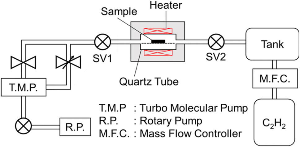 | ||
| Fig. 1 Schematic illustration of the thermal chemical vapor deposition apparatus. | ||
Results and discussion
Synthesis of the core MARIMO catalysts
Nanosized metal oxide catalysts supported in the MARIMO sub-micron-sized spheres were synthesized by two different methods: the one-pot solvothermal method and the two-step impregnation method. Fig. 2 illustrates the two synthesis approaches used to yield FeOx catalysts supported in/on MARIMO ZrO2 as an example.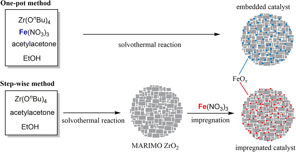 | ||
| Fig. 2 One-pot solvothermal synthesis of FeOx catalyst embedded in ZrO2 MARIMO (top) and step-wise preparation of FeOx catalyst impregnated in MARIMO ZrO2 (bottom). | ||
First, nanosized metal oxide catalysts (FeOx, CoOx, and NiOx) that was embedded in the support metal oxides were prepared using our original one-pot and single-step solvothermal method.19 The synthesis procedure was very simple. For example, a precursor solution that included Zr(OnBu)4, Fe(NO3)3‧9H2O, and acetylacetone in ethanol was heated up to 250 °C in an SUS316 pressure vessel. The powdery product obtained was washed with methanol and dried in a vacuum, yielding sFeOx/ZrO2-M with different FeOx contents (see Table 1). In the sNiOx/ZrO2-M case except for s20-NiOx/ZrO2-M, a solution that included Zr(OnBu)4, Ni(NO3)2‧6H2O, and diethylene glycol in acetonitrile was used as the precursor solution. The combination of Co(NO3)2 and Zr(OnBu)4 with acetylacetone in ethanol and the combination of Fe(NO3)3 and Ce(NO3)3 with diethylene glycol and benzoic acid in methanol produced sCoOx/ZrO2-M and sFeOx/CeO2-M spheres, respectively, using procedures that were slightly modified relative to the previously reported method.19,22
Nanosized metal oxide catalysts (FeOx, CoOx, and NiOx) that were impregnated in the support metal oxides (TiO2, ZrO2, SnO2, and CeO2) were prepared by the conventional impregnation method, which is quite a versatile technique in the catalyst preparation field for fabrication of supported nanometal catalysts.31 TiO2,15 ZrO2,19 SnO2,21 and CeO2 (ref. 22) MARIMOs were prepared using the previously reported solvothermal methods; these oxides are ideal materials for dispersion of catalyst metal (oxide) particles on their surfaces because they have unique nano-concave-convex surfaces, high specific surface areas (150–220 m2 g−1; see Fig. S1 and Table S1†), and large numbers of pores for good dispersion of the nanometal oxide catalysts used for CNT growth. FeOx was loaded on these MARIMOs by the impregnation method using Fe(NO3)3‧9H2O to yield i5-FeOx/ZrO2-M, i10-FeOx/ZrO2-M, i20-FeOx/ZrO2-M, i30-FeOx/ZrO2-M, i50-FeOx/ZrO2-M, i20-FeOx/TiO2-M, i20-FeOx/SnO2-M, and i20-FeOx/CeO2-M spheres (Table 2). Similarly, i20-FeOx/ZrO2-W and i20-FeOx/ZrO2-U spheres were also prepared as reference catalysts by the impregnation method, where “W” and “U” represent “Wako ZrO2” and “UEP-100 ZrO2,” respectively. Similarly, NiOx was loaded on ZrO2-M using Ni(NO3)2·6H2O to yield i8-NiOx/ZrO2-M.
Physical properties of the core MARIMO catalysts
Specific surface areas of the solvothermally embedded catalysts were estimated to compare with those of native MARIMO supports. In the cases of sFeOx/ZrO2-M, s20-CoOx/ZrO2-M, and s20-NiOx/ZrO2-M, their specific surface areas are so high (182–269 m2 g−1) (see Fig. S1 and Table S1†). However, further incorporation of NiOx into ZrO2-M support by the solvothermal method resulted in drastic decrease of the specific surface areas (6–36 m2 g−1), which can be ascribed to blockage of the pores of the MARIMO supports with the much amount of the introduced nanosized catalyst metal oxides as BJH plots indicate (see Fig. S1B†). Similarly, s50-FeOx/CeO2-M also exhibited quite low specific surface area (8 m2 g−1).
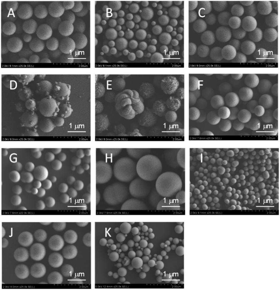 | ||
| Fig. 3 SEM images of catalysts prepared using the solvothermal method. (A) s5-FeOx/ZrO2-M, (B) s10-FeOx/ZrO2-M, (C) s20-FeOx/ZrO2-M, (D) s30-FeOx/ZrO2-M, (E) s50-FeOx/ZrO2-M, (F) s20-CoOx/ZrO2-M, (G) s20-NiOx/ZrO2-M, (H) s30-NiOx/ZrO2-M, (I) s50-NiOx/ZrO2-M, (J) s70-NiOx/ZrO2-M and (K) s50-FeOx/CeO2-M. | ||
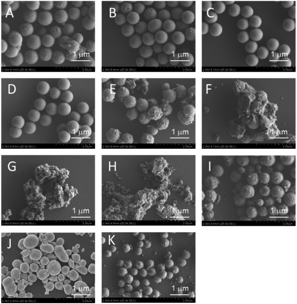 | ||
| Fig. 4 SEM images of catalysts prepared using the impregnation method. (A) i8-NiOx/ZrO2-M, (B) i5-FeOx/ZrO2-M, (C) i10-FeOx/ZrO2-M, (D) i20-FeOx/ZrO2-M, (E) i30-FeOx/ZrO2-M, (F) i50-FeOx/ZrO2-M, (G) i20-FeOx/ZrO2-W, (H) i20-FeOx/ZrO2-U, (I) i20-FeOx/TiO2-M, (J) i20-FeOx/SnO2-M and (K) i20-FeOx/CeO2-M. | ||
As shown in Fig. 3A–C, ZrO2 catalysts that included 5 to 20 atom% FeOx with striking spherical morphologies were obtained; their XRD spectra showed quite broad peaks that were ascribed to cubic ZrO2 (see Fig. S4A–C†). Judging from the peak positions (2θ), FeOx, CoOx, or NiOx did not yield solid solutions with MARIMO ZrO2 support (see Fig. S4†). Further introduction of larger amounts of FeOx caused swellings on the MARIMO surfaces (Fig. 3D and E), for which the corresponding XRD spectra showed clear peaks that were ascribed to cubic Fe3O4 (see Fig. S3D and E†). Therefore, introduction of too much FeOx caused irregular shapes to occur and led to the formation of large-sized Fe3O4 particles. In contrast, 20 atom% CoOx catalyst embedded in ZrO2 MARIMO produced perfectly spherical morphologies (Fig. 3F). In addition, 20–70 atom% NiOx catalysts embedded in ZrO2 MARIMOs also exhibited perfectly spherical morphologies (Fig. 3G–J). 50 atom% FeOx catalyst embedded in CeO2 MARIMO also showed a spherical morphology, including both large- and small-sized spheres (Fig. 3K).
As an alternative, the impregnation method is a simple preparation technique that can be used to obtain supported catalysts.31 In addition, this method is a versatile technique that is applicable to almost all types of support. We applied this technique to obtain NiOx and FeOx catalysts that were supported on several types of MARIMO support. XRD spectra indicated that the ZrO2 MARIMO supports for the impregnated catalysts showed a cubic crystal phase (see Fig. S5B–F†). Interestingly, i8-NiOx/ZrO2-M consisted of cubic and monoclinic crystal phases (see Fig. S5A†). The inherently spherical morphologies of the MARIMO supports were clearly preserved in the cases of 5 to 20 atom% impregnation of NiOx and FeOx in the ZrO2 MARIMO (Fig. 4A–D). However, further loading of larger quantities of FeOx into the ZrO2 MARIMO (30 and 50 atom%) resulted in catalysts with rugged structures (Fig. 4E and F). Therefore, loading of more than 30 atom% of FeOx on the ZrO2 MARIMO support by the impregnation method was not suitable for our purpose of preparing spherical catalysts for CNT growth. Furthermore, commercially available ZrO2 particles, comprising the Wako ZrO2 and UEP-100 ZrO2 particles, without spherical morphologies were also converted into FeOx/ZrO2 catalysts via the impregnation method to act as reference samples (Fig. 4G and H, respectively), with the ZrO2 supports showing a monoclinic crystal phase in this case (see Fig. S5G and H†). In the cases of the spherical TiO2, SnO2, and CeO2 MARIMO supports, globular morphologies were observed for the impregnated catalysts after FeOx loading (Fig. 4I–K, respectively). Therefore, we prepared catalyst candidate materials to obtain the MARIMO-CNT conjugates successfully.
Thermal CVD of the prepared catalysts
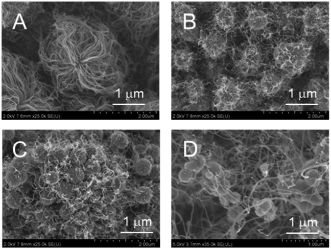 | ||
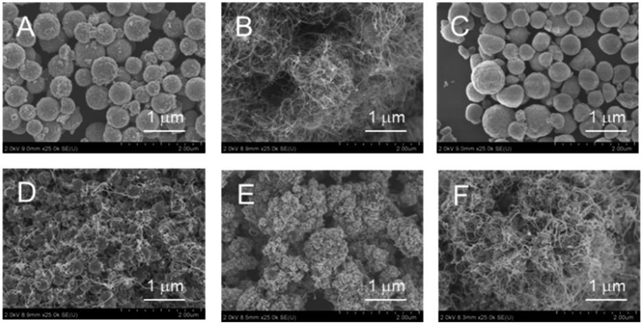
| Fig. 5 SEM images of CNT-hair obtained using different catalysts, including (A) s20-FeOx/ZrO2-M, (B) s20-CoOx/ZrO2-M, (C) s20-NiOx/ZrO2-M and (D) s50-FeOx/CeO2-M at 730 °C under pressure of 65 Pa with a 10 sccm ethyne gas flow for 10 s. | ||
Next, the amount of loaded Fe was varied to optimize the CNT-hair formation process (Fig. 6). The amount and the length of CNT-hair increased for Fe loading of up to 20 atom% (Fig. 6A–C), but the spherical catalyst cores themselves can be seen through the CNT-hair when the amount of Fe exceeded 30 atom% (Fig. 6D and E). Therefore, we decided to use 20 atom% of Fe catalyst in the later experiments.
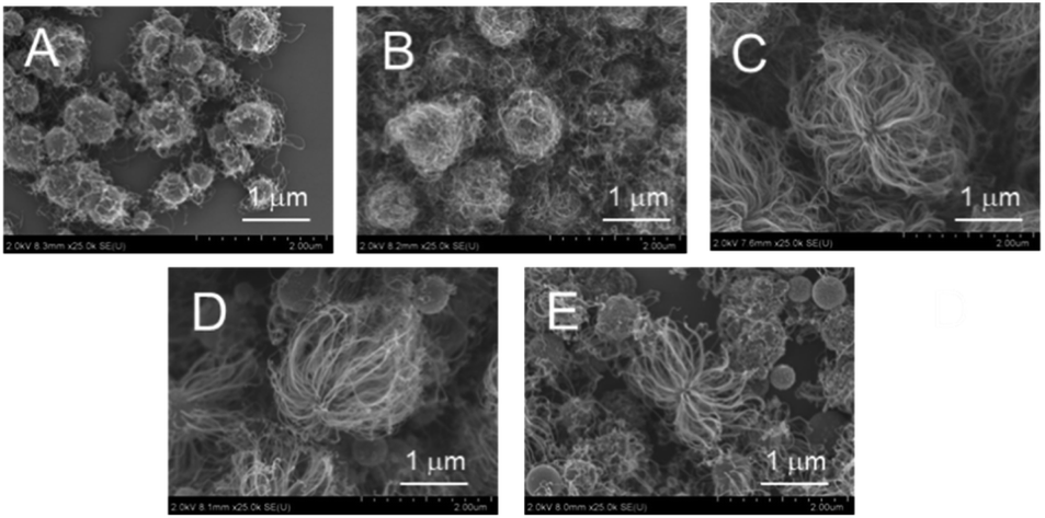 | ||
| Fig. 6 SEM images of CNT-hair obtained using different quantities of catalysts, including (A) s5-FeOx/ZrO2-M, (B) s10-FeOx/ZrO2-M, (C) s20-FeOx/ZrO2-M (the same as Fig. 5A), (D) s30-FeOx/ZrO2-M and (E) s50-FeOx/ZrO2-M at 730 °C under pressure of 65 Pa with a 10 sccm ethyne gas flow for 10 s. | ||
The reaction temperature was varied (670, 730, and 760 °C) while using s20-FeOx/ZrO2-M as the catalyst (Fig. 7). The CNT-hair seemed to grow well at all temperatures tested. To determine the quality of the CNTs, the IG/ID intensity ratios in the Raman spectra were estimated (see Fig. S6†), whose ratios of the G and D bands (IG/ID) in the Raman spectra were used to determine the crystallinity of the CNT-hair obtained. G band, in-plane bond stretching mode of the C–C bonds in the hexagonal lattice,32 represents the higher concentration of sp2 carbon atoms and higher-ordered graphitic structures. While the D band, hexagonal sp2 breathing mode, indicates the presence of defects in sp2 network.33 The CNT-hair obtained at 730 °C (1.88) was found to show the best crystallinity than those obtained at 670 °C (0.71) and 760 °C (0.82).
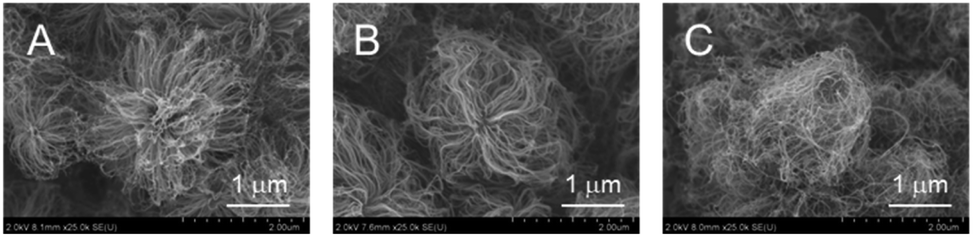 | ||
| Fig. 7 SEM images of CNT-hair obtained using s20-FeOx/ZrO2-M catalysts at temperatures of (A) 670 °C, (B) 730 °C (the same as Fig. 5A) and (C) 760 °C under pressure of 65 Pa with a 10 sccm ethyne gas flow for 10 s. | ||
With regard to the reaction time, small perturbances were observed with the short reaction time of 0.5 s (Fig. 8A), while CNT-hair of sufficient length was produced after 10 s (Fig. 8D), this indicating that a sufficient quantity of the ethyne gas is indispensable for formation of the CNT-hair conjugates.
 | ||
| Fig. 8 SEM images of products obtained using s20-FeOx/ZrO2-M catalysts with different reaction times at 730 °C under pressure of 65 Pa with a 10 sccm ethyne gas flow. (A) 0.5 s, (B) 1 s, (C) 3 s and (D) 10 s (the same as Fig. 5A). | ||
In summary for this section, in which nanosized metal oxide catalysts embedded in metal oxide supports were used, the reaction conditions when using the s20-FeOx/ZrO2-M catalysts at 730 °C under pressure of 65 Pa with 10 sccm ethyne gas flow for 10 s were the best conditions for CNT-hair formation.
 | ||
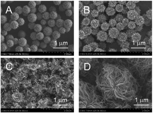
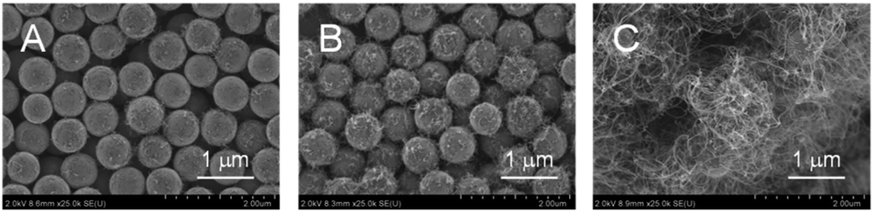
| Fig. 9 SEM images of products obtained using FeOx catalysts supported on different metal oxides. (A) i20-FeOx/TiO2-M, (B) i20-FeOx/ZrO2-M, (C) i20-FeOx/SnO2-M, (D) i20-FeOx/CeO2-M, (E) i20-FeOx/ZrO2-W and (F) i20-FeOx/ZrO2-U at 730 °C under pressure of 65 Pa with a 10 sccm ethyne gas flow for 10 s. | ||
The quantities of the loaded FeOx were critical to effective production of the CNT-hair. Smaller amounts of Fe atoms (5 and 10 atom%) in the MARIMO ZrO2 support were not effective in yielding CNT-hair (Fig. 10A and B). However, larger quantities of Fe atoms (20 atom%) on the MARIMO ZrO2 support led to effective CNT-hair growth (Fig. 10C). The reaction temperature was also important to the formation of the CNT-hair. Almost zero CNT-hair formation was observed at the lower temperature of 670 °C (Fig. 11A). However, use of the higher temperatures of 730 °C and 760 °C resulted in the formation of satisfactory CNT-hair (Fig. 11B and C).
 | ||
| Fig. 10 SEM images of products obtained using catalysts with different quantities of FeOx. (A) i5-FeOx/ZrO2-M, (B) i10-FeOx/ZrO2-M and (C) i20-FeOx/ZrO2-M (the same as Fig. 9B) at 730 °C under pressure of 65 Pa with a 10 sccm ethyne gas flow for 10 s. | ||
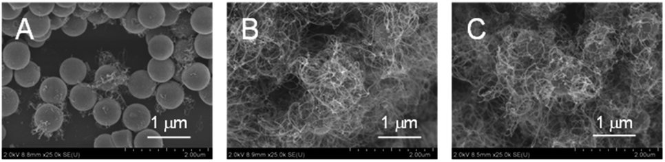 | ||
| Fig. 11 SEM images of products obtained using i20-FeOx/ZrO2-M at different temperatures. (A) 670 °C, (B) 730 °C (the same as Fig. 9B) and (C) 760 °C under pressure of 65 Pa with a 10 sccm ethyne gas flow for 10 s. | ||
As a conclusion for thermal CVD of the prepared catalysts Section, the combination of nanosized FeOx as the CNT catalyst and ZrO2 as the support was shown to be the best for production of CNT-hair under our reaction conditions, irrespective of use of a solvothermally embedded or impregnated FeOx/ZrO2 catalyst. In light of all the results obtained, we concluded that the best catalyst for CNT-hair formation was the 20 atom% FeOx catalyst supported in the MARIMO ZrO2 porous spheres. From this point, the reaction conditions were fixed as follows: use of the 20 atom% FeOx/ZrO2 catalyst at 730 °C under pressure of 65 Pa with a 10 sccm ethyne gas flow for 10 s.
Detailed observation of the CNT-hair
Fig. 12 shows SEM images of the products obtained using the solvothermally embedded s20-FeOx/ZrO2-M catalyst (Fig. 12A) and the impregnated i20-FeOx/ZrO2-M catalyst (Fig. 12B). In the embedded s20-FeOx/ZrO2-M case, a waved sheet-like product on a th-SiO2 substrate was observed under low magnification (Fig. 12A1). Expansion of the ripped area shows that the sheet consists of large numbers of particles (Fig. 12A2). The 5 μm-scale image clearly indicates that these particles are aggregates of multiple yarns, similar to fuzzy balls or cotton candies, with diameters of less than 3 μm (Fig. 12A3). Further expansion clearly shows that the aggregates include dark spherical cores and long gray threads (ca. 3 nm in length) (Fig. 12A4), which can be ascribed to the FeOx/ZrO2 MARIMO core and the CNTs, respectively. In the same manner, the impregnated i20-FeOx/ZrO2-M catalyst produced similar CNT-hair (Fig. 12B), but the density of the CNTs on the impregnated i20-FeOx/ZrO2-M catalyst appeared to be slightly lower than that obtained on the embedded s20-FeOx/ZrO2-M catalyst (Fig. 12A3, A4, B3, B4 and S7, S8†).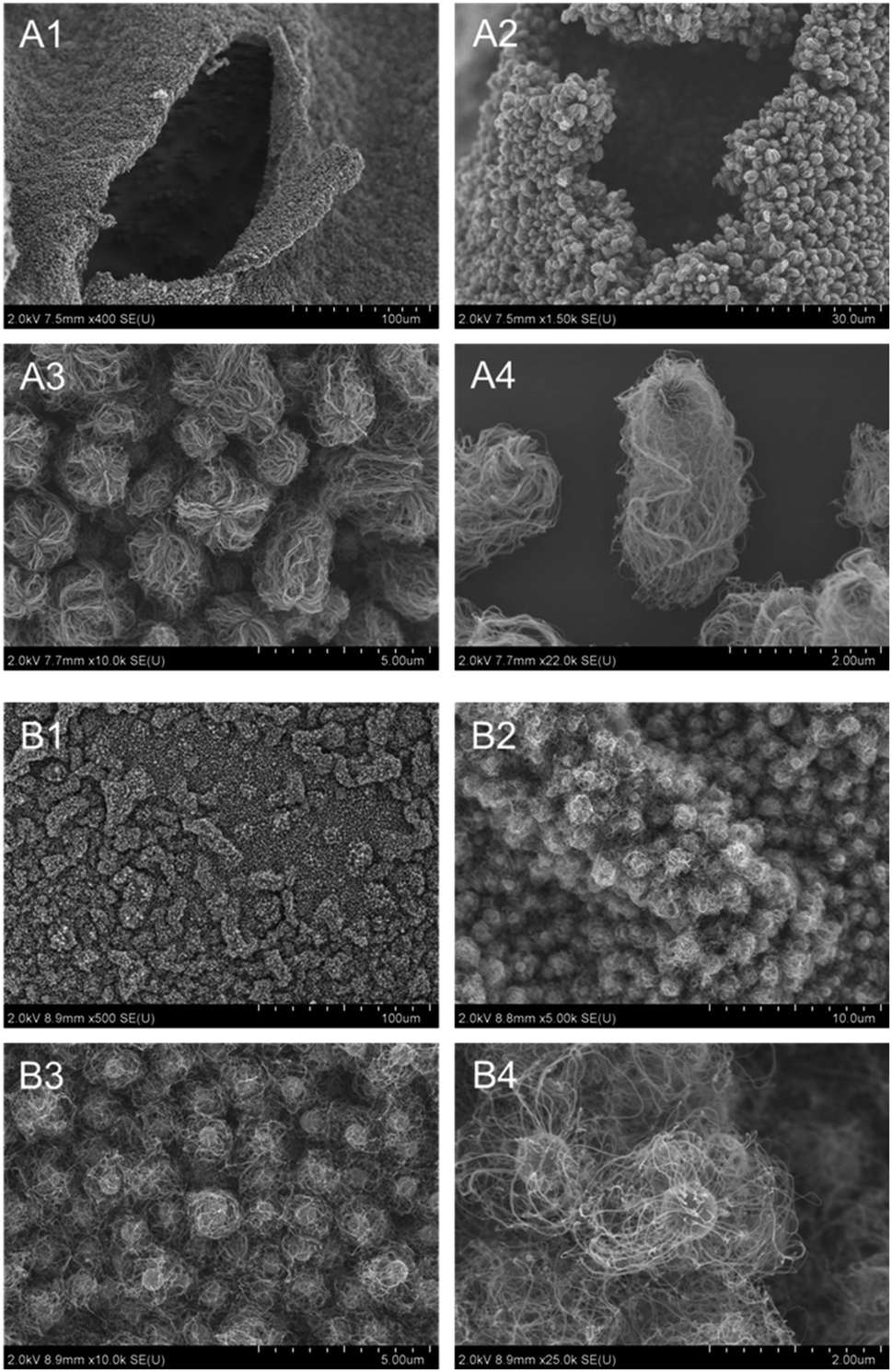 | ||
| Fig. 12 SEM images of CNT-hairs at different magnifications obtained using (A) s20-FeOx/ZrO2-M and (B) i20-FeOx/ZrO2-M catalysts at 730 °C under pressure of 65 Pa with a 10 sccm ethyne gas flow for 10 s. | ||
Further expansions clearly show that the CNTs grew upward from the surface of the core FeOx/ZrO2 MARIMOs (Fig. 13A3, A4, B3 and B4). Another unique feature of the CNT-hair can be seen in Fig. 13A1, A2, B1 and B2. The CNT-hairs were entangled with each other to show a structure similar to a nonwoven fabric, which constructs CNT grids with junctions formed by the ZrO2 MARIMOs. Furthermore, the combination of the black core FeOx/ZrO2 MARIMOs with the CNTs appears similar to frog eggs. A single long CNT is soft and flexible. However, when multiple CNTs come together, they support each other, creating a new CNT forest morphology.5,6 Similar to the CNT forest, the CNTs in the CNT-hair are soft and flexible. However, when large numbers of CNT-hairs come together, they become tangled with each other, yielding a new morphology like the observed CNT-frog eggs structure. Based on these observations, the layered materials obtained by constructed with large amounts of CNT-hair can show intriguing physical properties, including isotropic absorption of polarized electromagnetic waves.
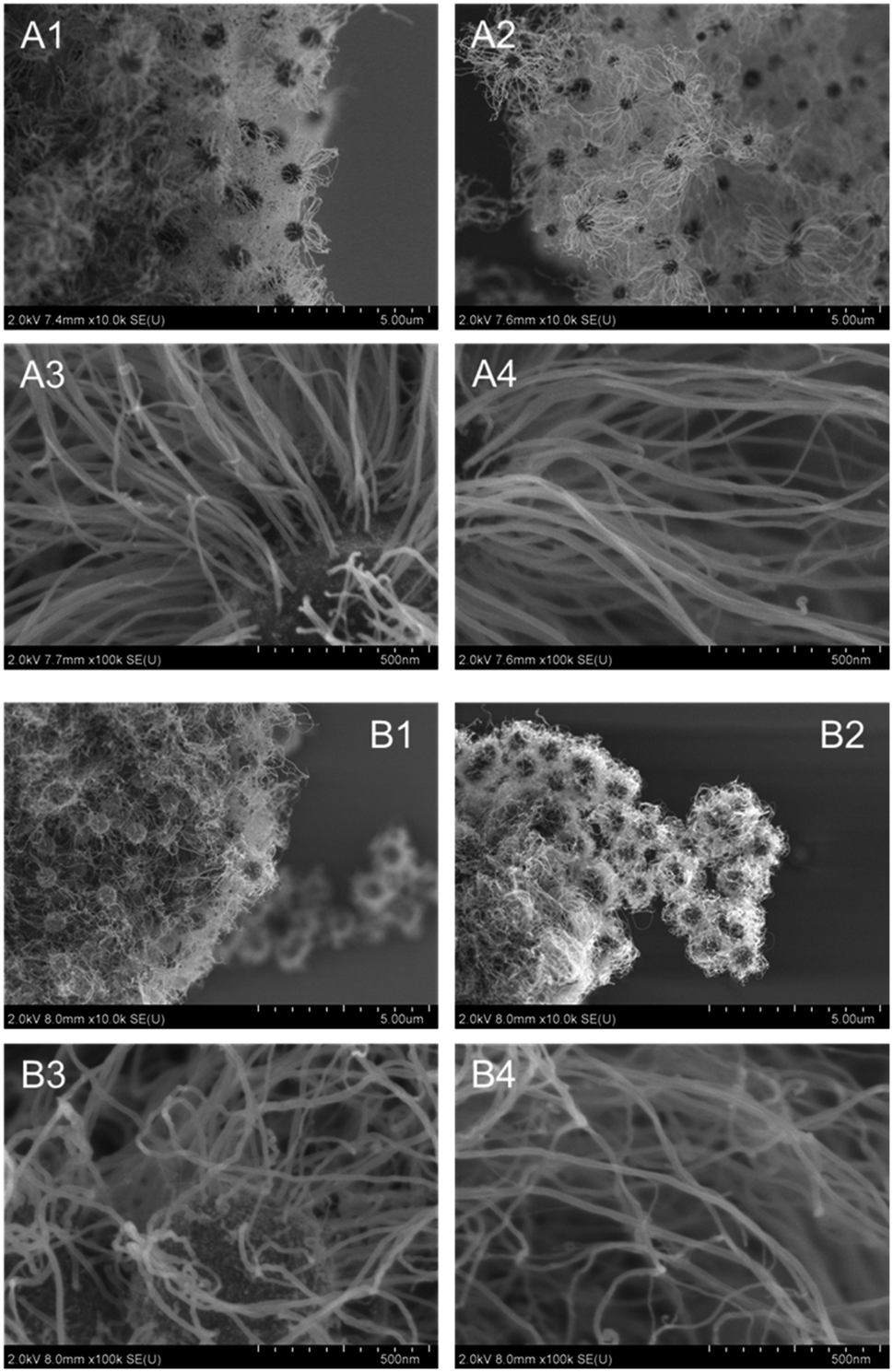 | ||
| Fig. 13 SEM images of CNT-hairs at different magnifications obtained using (A) s20-FeOx/ZrO2-M and (B) i20-FeOx/ZrO2-M catalysts at 730 °C under pressure of 65 Pa with a 10 sccm ethyne gas flow for 10 s. | ||
TEM images clearly show that the CNT-hairs grew from the surface of the core MARIMO catalysts regardless of whether the catalyst was embedded or impregnated (Fig. 14). In addition, the CNTs obtained were ascertained to be multi-walled structures with 5–8 layers. To determine the diameter distribution of the CNT-hairs, the diameters of 100 tubes in the TEM images were estimated (Fig. 15). As a result, the CNT diameter distribution obtained when using the embedded s20-FeOx/ZrO2-M catalyst showed two maxima of 12 and 24 nm, with an average value of 14.8 nm and a 5.4 nm dispersion, while the corresponding results obtained using the impregnated i20-FeOx/ZrO2-M catalyst showed a smaller average value (13.8 nm) with a lower dispersion (2.3 nm). Therefore, the CNT-hair obtained using the embedded s20-FeOx/ZrO2-M catalyst was dense, thick, and straight, while that obtained using the impregnated i20-FeOx/ZrO2-M catalyst was a little sparse, thin, and curly (see Fig. 12–15).
 | ||
| Fig. 14 TEM images of CNT-hairs at different magnifications obtained using (A) s20-FeOx/ZrO2-M and (B) i20-FeOx/ZrO2-M catalysts at 730 °C under pressure of 65 Pa with a 10 sccm ethyne gas flow for 10 s. | ||
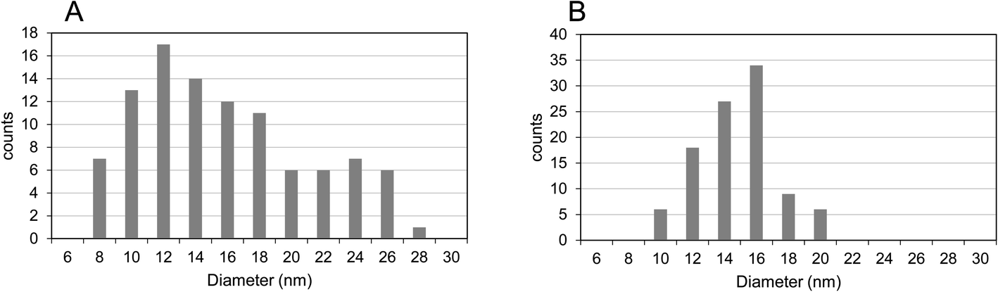 | ||
| Fig. 15 Diameter distributions of CNT-hairs obtained using (A) s20-FeOx/ZrO2-M catalyst and (B) i20-FeOx/ZrO2-M catalyst at 730 °C under pressure of 65 Pa with a 10 sccm ethyne gas flow for 10 s. | ||
To determine the crystallinity of the CNT-hair obtained, the intensity ratios of the G and D bands IG/ID in the Raman spectra were estimated (Fig. 16). Consequently, the CNT-hair obtained using s20-FeOx/ZrO2-M (1.88) was found to show better crystallinity than that obtained using i20-FeOx/ZrO2-M (1.12). The G′ (or 2D) band at around 2700 cm−1 originates from the second-order Raman scattering, arising from a two-phonon, intervalley, second-order Raman scattering process.34 The sharp and higher intensity of the G′ band represents the lower concentration of defects and disorders and lower interaction between graphene layers, indicating a high-quality lower number of layers, especially for single-walled carbon nanotubes. The intensity ratio of the G′ and G band in CNTs grown at 730 °C on s20-FeOx/ZrO2-M (IG′/IG = 0.56) was higher than that on i20-FeOx/ZrO2-M catalysts (IG′/IG = 0.45). Sharp G′ band and higher IG′/IG of CNTs on s20-FeOx/ZrO2-M catalysts indicate higher quality of carbon nanotube formation, compared with i20-FeOx/ZrO2-M catalysts. As shown in Fig. 14A4 and B4, crystal structure order was confirmed higher for CNTs on s20-FeOx/ZrO2-M catalysts (Fig. 14A4) compared with i20-FeOx/ZrO2-M catalysts (Fig. 14B4).
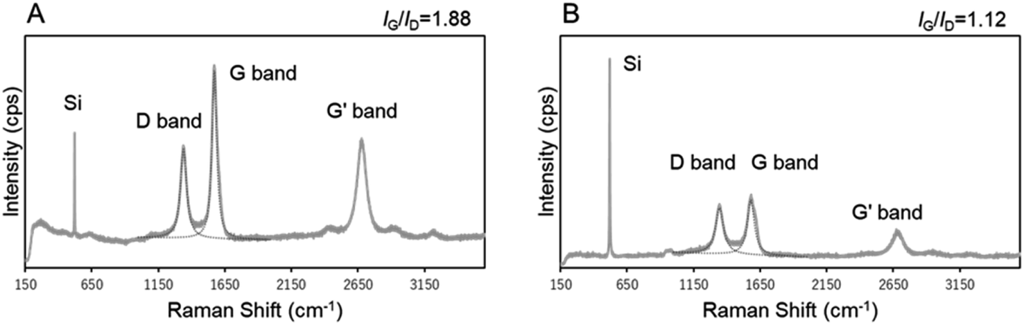 | ||
| Fig. 16 Raman spectra of CNT-hairs obtained using (A) s20-FeOx/ZrO2-M and (B) i20-FeOx/ZrO2-M catalysts at 730 °C under pressure of 65 Pa with a 10 sccm ethyne gas flow for 10 s. The Si peaks at 520 cm−1 were observed in both samples on the th-SiO2 substrates on which MARIMO catalysts were drop-cast. | ||
Conclusions
Catalysts that were suitable for CNT-hair preparation were studied extensively. FeOx, CoOx, and NiOx were selected as the CNT catalysts, and TiO2, ZrO2, SnO2, and CeO2 were selected as the support materials. Supported catalysts with different combinations of these catalysts and supports were prepared by two different methods, comprising the one-step solvothermal method and the two-step impregnation method, and yielded impregnated catalysts and embedded catalysts, respectively. Among the catalyst candidates, the combination of FeOx as the catalyst for CNT growth and ZrO2 as the support resulted in the best growth of CNTs under the required reaction conditions of a temperature of 730 °C under pressure of 65 Pa with a 10 sccm ethyne gas flow for a reaction time of 10 s. These CNTs consisted of 5–8 layered multi-wall structures and the length of these CNTs reached approximately 3 μm. The CNT-hair that was obtained using the solvothermally embedded catalyst showed higher crystallinity and was dense, thick, and straight, while that obtained using the impregnated catalyst was a little sparse, thin, and curly. A unique structure consisting of multiple CNT yarns, similar to fuzzy balls or cotton candies, was produced. Multiple CNT-hair conjugates came together to yield a layer structure, in which the core FeOx/ZrO2 catalysts and CNT yarns appeared to be structured like frog eggs. Based on these observations, the layer materials obtained from construction with large amounts of CNT-hair are expected to exhibit intriguing physical properties, including isotropic absorption of polarized light and electromagnetic waves. Further studies of the physical properties of these materials are now in progress.Author contributions
Kazuya Kobiro: funding acquisition, project administration, resources, supervision, writing – review & editing. Hinako Kimura: data curation, formal analysis, investigation, methodology, visualization. Saki Hirose: data curation, formal analysis, investigation, methodology, visualization. Makoto Kinjo: data curation, formal analysis, investigation. Hiroshi Furuta: conceptualization, methodology, project administration, writing – review & editing.Conflicts of interest
There are no conflicts to declare.Acknowledgements
This work was partially supported by the JSPS KAKENHI (grant numbers 20K05093 and 22K04819). We thank David MacDonald, MSc, from Edanz (https://jp.edanz.com/ac) for editing a draft of this manuscript.References
- S. Iijima, Nature, 1991, 354, 56–57 CrossRef CAS.
- D. Y. Kim, H. Sugime, K. Hasegawa, T. Osawa and S. Noda, Carbon, 2012, 50, 1538–1545 CrossRef CAS.
- M. Li, S. Hachiya, Z. Chen, T. Osawa, H. Sugime and S. Noda, Carbon, 2021, 182, 23–31 CrossRef CAS.
- J. De La Verpilliere, S. Jessl, K. Saeed, C. Ducati, M. De Volder and A. Boies, Nanoscale, 2018, 10, 7780–7791 RSC.
- A. Pander, K. Takano, A. Hatta, M. Nakajima and H. Furuta, Opt. Express, 2020, 28, 607–625 CrossRef CAS PubMed.
- H. Miyaji, A. Pander, K. Takano, H. Kohno, A. Hatta, M. Nakajima and H. Furuta, Diamond Relat. Mater., 2018, 83, 196–203 CrossRef CAS.
- D. He, M. Bozlar, M. Genestoux and J. Bai, Carbon, 2010, 48, 1159–1170 CrossRef CAS.
- S.-Y. Park, W.-D. Kim, D.-G. Kim, J.-K. Kim, Y.-S. Jeong, J. H. Kim, J. K. Lee, S. H. Kim and J.-W. Kang, Sol. Energy Mater. Sol. Cells, 2010, 94, 750–754 CrossRef CAS.
- Y. Piao, K. An, J. Kim, T. Yu and T. Hyeon, J. Mater. Chem., 2006, 16, 2984–2989 RSC.
- D. Y. Kim, H. Sugime, K. Hasegawa, T. Osawa and S. Noda, Carbon, 2011, 49, 1972–1979 CrossRef CAS.
- C. Jo, A. S. Groombridge, J. De La Verpilliere, J. T. Lee, Y. Son, H.-L. Liang, A. M. Boies and M. De Volder, ACS Nano, 2020, 14, 698–707 CrossRef CAS PubMed.
- F. S. Boi, G. Mountjoy and M. Baxendale, Carbon, 2013, 64, 516–526 CrossRef.
- T. Chen, B. Cheng, G. Zhu, R. Chen, Y. Hu, L. Ma, H. Lv, Y. Wang, J. Liang, Z. Tie, Z. Jin and J. Liu, Nano Lett., 2017, 17, 437–444 CrossRef CAS PubMed.
- A. B. D. Nandiyanto, Y. Kaihatsu, F. Iskandar and K. Okuyama, Mater. Lett., 2009, 63, 1847–1850 CrossRef CAS.
- P. Wang and K. Kobiro, Pure Appl. Chem., 2014, 86, 785–800 CAS.
- E. K. C. Pradeep, M. Ohtani, T. Kawaharamura and K. Kobiro, Chem. Lett., 2017, 46, 940–943 CrossRef CAS.
- P. Wang and K. Kobiro, Chem. Lett., 2012, 41, 264–266 CrossRef CAS.
- P. Wang, H. Takigawa, K. Ueno and K. Kobiro, J. Supercrit. Fluids, 2013, 78, 124–131 CrossRef CAS.
- K. Kan, E. Yamamoto, M. Ohtani and K. Kobiro, Eur. J. Inorg. Chem., 2020, 4435–4441 CrossRef CAS.
- Y. Kumabe, H. Taga, K. Kan, M. Ohtani and K. Kobiro, RSC Adv., 2020, 10, 14630–14636 RSC.
- A. Taniguchi, R. Miyata, M. Ohtani and K. Kobiro, RSC Adv., 2022, 12, 22902–22910 RSC.
- A. Taniguchi, Y. Kumabe, K. Kan, M. Ohtani and K. Kobiro, RSC Adv., 2021, 11, 5609–5617 RSC.
- E. K. C. Pradeep, M. Ohtani and K. Kobiro, Eur. J. Inorg. Chem., 2015, 5621–5627 CrossRef CAS.
- H. T. T. Nguyen, T. Habu, M. Ohtani and K. Kobiro, Eur. J. Inorg. Chem., 2017, 3017–3023 CrossRef CAS.
- Y. Tanaka, H. Usui, Y. Domi, M. Ohtani, K. Kobiro and H. Sakaguchi, ACS Appl. Energy Mater., 2019, 2, 636–643 CrossRef CAS.
- M. Meiliefiana, T. Nakayashiki, E. Yamamoto, H. Hayashi, M. Ohtani and K. Kobiro, Nanoscale Res. Lett., 2022, 17, 47 CrossRef CAS PubMed.
- E. K. C. Pradeep, T. Habu, H. Tooriyama, M. Ohtani and K. Kobiro, J. Supercrit. Fluids, 2015, 97, 217–223 CrossRef CAS.
- M. Ohtani, T. Muraoka, Y. Okimoto and K. Kobiro, Inorg. Chem., 2017, 56, 11546–11551 CrossRef CAS PubMed.
- https://www.ujiden-net.co.jp/marimo/, accessed Feb 05, 2023.
- F. Duriyasart, A. Irizawa, K. Hayashi, M. Ohtani and K. Kobiro, ChemCatChem, 2018, 10, 3392–3396 CrossRef CAS.
- X. Song, F. Shao, Z. Zhao, X. Li, Z. Wei and J. Wang, ACS Catal., 2022, 12, 14846–14855 CrossRef CAS.
- A. Jorio and R. Saito, J. Appl. Phys., 2021, 129, 021102 CrossRef CAS.
- A. C. Ferrari and J. Robertson, Phys. Rev. B: Condens. Matter Mater. Phys., 2000, 61, 14095–14107 CrossRef CAS.
- M. S. Dresselhaus, G. Dresselhaus, R. Saito and A. Jorio, Phys. Rep., 2005, 409, 47–99 CrossRef.
Footnote |
| † Electronic supplementary information (ESI) available. See DOI: https://doi.org/10.1039/d3ra00770g |
| This journal is © The Royal Society of Chemistry 2023 |