
 Open Access Article
 This Open Access Article is licensed under a Creative Commons Attribution-Non Commercial 3.0 Unported Licence
Design of blueberry anthocyanin/TiO2 composite layer-based photoanode and N-doped porous blueberry-derived carbon-loaded Ni nanoparticle-based counter electrode for dye-sensitized solar cells†
Xiang Qin‡
ab,
Jingjing Liu‡ab,
Genhui Tengab,
Baorui Liuab,
Yanhui Xieab,
Lin Maab and
Dongying Hu *ab
*ab
aSchool of Resources, Environment and Materials, Guangxi University, Nanning, 530004, China. E-mail: hdy@gxu.edu.cn; hdygxu@163.com; wxxxljj@163.com; Tel: +86-771-3232200
bState Key Laboratory of Featured Metal Materials and Life-cycle Safety for Composite Structures, Guangxi University, Nanning, 530004, China. E-mail: Qinxiang542968@163.com; 785631176@qq.com; 1319548675@qq.com
First published on 6th March 2023
Abstract
P25/PBP (TiO2, anthocyanins) prepared by combining PBP (blueberry peels) with P25, and N-doped porous carbon-supported Ni nanoparticles (Ni@NPC-X) prepared using blueberry-derived carbon were used for the application as photoanode and the counter electrode, respectively, in dye-sensitized solar cells (DSSCs) to create a new perspective for blueberry-based photo-powered energy systems. PBP was introduced into the P25 photoanode and carbonized to form a C-like structure after annealing that improved its adsorption capacity for N719 dye, contributing a 17.3% higher power conversion efficiency (PCE) of P25/PBP-Pt (5.82%) than that of P25-Pt (4.96%). The structure of the porous carbon changes from a flat surface to a petal-like structure due to the N doping by melamine, and the specific surface area increases. N-doped three-dimensional porous carbon supported the loading and reduced the agglomeration of Ni nanoparticles, reducing the charge transfer resistance, and providing a fast electron transfer path. The doping of Ni and N on the porous carbon worked synergistically to enhance the electrocatalytic activity of the Ni@NPC-X electrode. The PCE of the DSSCs assembled by Ni@NPC-1.5 and P25/PBP was 4.86%. Also, the Ni@NPC-1.5 electrode exhibited 116.12 F g−1 and a capacitance retention rate of 98.2% (10![[thin space (1/6-em)]](https://www.rsc.org/images/entities/char_2009.gif) 000 cycles), further confirming good electrocatalysis and cycle stability.
000 cycles), further confirming good electrocatalysis and cycle stability.
1 Introduction
The continuous progress of urbanization has put forward new demands and higher requirements for energy demand and sustainable development.1 Priority selection of clean energy is undoubtedly the right direction to solve the above problems. Solar cells can effectively convert clean-energy solar radiation into one of the most convenient forms of electricity, highlighting its dominant position.2,3 Among them, the design of dye-sensitized solar cells (DSSCs) is inspired by nature and then applied to the energy supply of the human environment through simple utilization.4 For DSSCs, the research on photoanodes and counter-electrode materials has never faded out of the research field due to its dominant position.5–7Taking the common titanium dioxide (TiO2) photoanode as basic, great effects have been adopted in improving the photoanode by means of micro–nano structure design, multiple heterogeneous doping, physical/chemical modification, and other methods. Compared with transition metal element doping and precious metal deposition, carbon material doping has attracted widespread attention due to its wide material sources and adjustable structure, including graphitic carbon nitride,8,9 carbon nanotubes, porous carbon, and graphite.10 Lu et al. doped hierarchical carbon nanofibers (CFs) in TiO2 and the photoelectron migration in the photoanode was improved.11 Khan et al. synthesized cobalt-reduced graphene oxide Co-doped TiO2 nanoparticles by the sol–gel method, which effectively improved the electron transport ability of the Co/rGO-TiO2 photoanode.12 The doping of carbon materials in the TiO2 layer is a very effective method to improve the electron collection characteristics of DSSCs devices.13 This is because the good conductivity of carbon-based materials and the synergistic effect of TiO2 photoelectric properties can effectively promote electron transport and inhibit electronic recombination. Moreover, carbon materials acting on the photoanode may have a certain positive effect on the improvement of dye absorption and catalytic photoelectric activity.14,15 Inspired by the above advantages, we mixed non-carbonized materials (such as chlorophyll and anthocyanins natural dyes) with TiO2 before doping and then calcined the mixture to form carbon materials naturally dispersed in TiO2. The abundant functional groups of anthocyanins, particularly hydroxyl and carboxyl groups can interact with the Ti–O bond on TiO2 molecules to form colored TiO2. The functional groups were adsorbed on TiO2 at high-temperature to form carbon materials and were evenly dispersed in TiO2. Compared with the traditional mechanical method of doping carbon materials into TiO2, the use of molecular bond adsorption could make the carbon materials disperse more evenly in TiO2, thereby reducing the obstruction of the electron shuttle and further increasing electron migration.
The commonly used CE is the rare and precious metal Pt, which is costly and harmful to the environment, and severely restricts the development and application of DSSCs.16 For this reason, research work on carbonaceous materials,17,18 transition metal compounds19 and intrinsic conducting polymers20 as alternatives to Pt has received attention. Among them, carbon-based materials have the advantages of low cost, strong electron transport ability, and corrosion resistance in electrolytes. However, the contact between carbon-based materials and the transparent conductive substrate is unstable, which seriously affects the electrocatalytic ability of the electrode. In addition, metal compounds are prone to corrosion when in contact with electrolytes, which limits their direct application.21 Yun et al. combined bio-based carbon (BC) with transition metal compounds (TMCs) for counter electrodes, and its PCE was about 15% and 74% higher than that of BC CE and TMC CE.22 Qureshi et al. synthesized a hybrid GO/Fe3O4 nanocomposite, which was also used as the counter electrode of DSSCs, and its PCE was 57% of Pt CE.23 Hence, the combination of carbon materials and metal compounds is an effective and direct means to improve the electrocatalytic properties of carbon-based materials and apply them as DSSCs. Compared with Pt, Ni, and Pt share similar valence electron configurations and adjacent positions, which are expected to be low-cost analogs of Pt. Wang et al. prepared NiCo2S4 nanoparticles loaded on carbon nanofibers (CNFs), benefitting from the tubular structure of CNFs, nickel and cobalt ions were loaded on the surface of CNFs to exhibit high conductivity.24 Based on these, we used the residue after extracting the pigment from blueberries to prepare N-doped blueberry-derived porous carbon-loaded Ni nanoparticles (Ni@NPC-X) for use in DSSC counter electrodes.
Herein, we have creatively designed two functional electrode materials (photoanode, counter electrode) with blueberries as the key performance improvement, and verified the contribution of blueberries to the DSSC electrode. The P25/PBP photoanode was prepared by mixing TiO2 (P25) and the blueberry dye, while the Ni@NPC-X counter electrode was prepared by loading Ni nanoparticles onto biomass blueberry-based N-doped carbon material. The elemental composition, structural composition, surface morphology, and photovoltaic parameters were analyzed by XRD, Raman spectroscopy, XPS, SEM, and J–V curves. The electrochemical characteristics of the Ni@NPC-X material in the supercapacitor electrodes were used to further confirm their excellent electrocatalytic performance and energy storage capacity. This research provided new ideas for blueberry-based photovoltaic-electric energy systems.
2 Experimental sections
2.1 Materials and reagents
Nickel acetate tetrahydrate (Ni(CH3COO)2·4H2O), chloroplatinic acid hexahydrate (H2PtCl6·6H2O), Ru-based photo-sensitizer dye (N719) were provided by Aladdin Chemical Reagent Co., Ltd (Shanghai, China). Polymer spacers (Surlyn) with a thickness of 60 μm and FTO glass slides with a size of 2.5 × 2 cm (resistivity of ∼7 ohm sq−1) were provided by Yingkou Opivite New Energy Technology Co., Ltd (Yingkou, Liaoning, China). Fresh blueberries (produced in Peru) were obtained from Beijing Jingdong Century Trading Co., Ltd (Beijing, China).2.2 Preparation of electrode materials
The preparation strategy of the Ni@NPC-X composite is represented in Fig. S1.† Blueberry powder (BP) was pre-carbonized in nitrogen at 700 °C for 2 h to obtain a pre-carbonized BP. 1 g of pre-carbonized BP was added to 20 ml of 2 g KOH solution and homogenized by stirring at 25 °C for 4 h. The mixed solution was concentrated at 70 °C for 24 h, then annealed at 700 °C for 2 h in nitrogen, and after the temperature dropped to 25 °C, the resulting sample was stirred in 1 M HCl for 2 h. The samples were then purified with distilled water and ethanol until the cleaning solution was neutral, and dried at 80 °C to obtain PC. 1 g of PC, 0.5 g of Ni(CH3COO)2·4H2O, and 1 g of melamine (1.5 g or 2 g) were added into 60 ml distilled water, hydrothermal heating at 160 °C for 12 h, and then annealing at 600 °C for 3 h under N2 atmosphere. Finally, the N-doped porous carbon composites loaded with Ni nanoparticles were obtained and named Ni@NPC-X (X = 1, 1.5, and 2, representing the amount of melamine added). In addition, in order to compare the effect of N-doping, Ni@PC was prepared by the same method, except that melamine was not added.
2.3 Assembling of DSSCs
:15 v%) was filled into the through hole of the CE cell, and then the hole was sealed with a sealing film.2.4 Characterization and performance tests
The physical/chemical structures of the DSSCs electrodes were characterized using an X-ray diffractometer (XRD), scanning electron microscope (FE-SEM), X-ray photoelectron spectroscopy (XPS), Fourier transform infrared spectrometer (FTIR), Raman spectrometer, and Brunau–Emmett–Taylor (BET), as detailed in the ESI.† DSSCs performance tests included photocurrent density voltage (J–V) curves, electrochemical impedance spectroscopy, Tafel polarization, cyclic voltammetry, and open circuit voltage decay (OCVD) curves, as detailed in the ESI.†3 Results and discussion
3.1 Morphology and composition analysis
In order to explore the effect of PBP doping on the morphology of P25 particles, P25 and P25/PBP were characterized by SEM. The surface of the P25 photoanode hints at the homogeneity of the TiO2 particle distribution (Fig. 1a–c). After adding PBP, the particle size of TiO2 in P25/PBP (Fig. 1e and f) increases, and the interparticle gap becomes larger, which can enable better adsorption of the N719 dye. Further, as shown in Fig. S2,† the addition of PBP increased the SBET of P25/PBP (36.89 m2 g−1) compared with P25 (24.59 m2 g−1), which is conducive to increasing the dye loading capacity of N719. | ||
| Fig. 1 SEM images of P25 (a–c) and P25/PBP (d–f). | ||
For CEs, it can be clearly seen that the blueberry powder-based carbon (PC) displayed a porous structure (Fig. 2a–c) originating from KOH-activated etching. In Ni@PC that is not doped with N, the Ni nanoparticles were loaded on the surface of PC, and the pore structure may have been covered, causing the diffusion of the electrolyte through the material to be hindered (Fig. 2d–f). Notably, when N was doped into the Ni@PC, the base morphology of the Ni@PC changed from a flat surface to a 3D petal-like shape (Fig. 2g–i). This promoted the diffusion of the electrolyte through the material, and the characteristic shape facilitated the loading of Ni nanoparticles. As shown in Fig. 2i, there were no other impurities on the surface of the Ni@NPC-1.5 composite material. Its morphology presented an open petal-like shape, and the size of the Ni particles loaded was ∼10 nm. Furthermore, the SEM mapping shown in Fig. 2j revealed the uniform elemental distribution of C, N, and Ni in the entire Ni@NPC-1.5, suggesting the uniformity of Ni nanoparticles on N-doped PC from the aspect of morphology distribution.
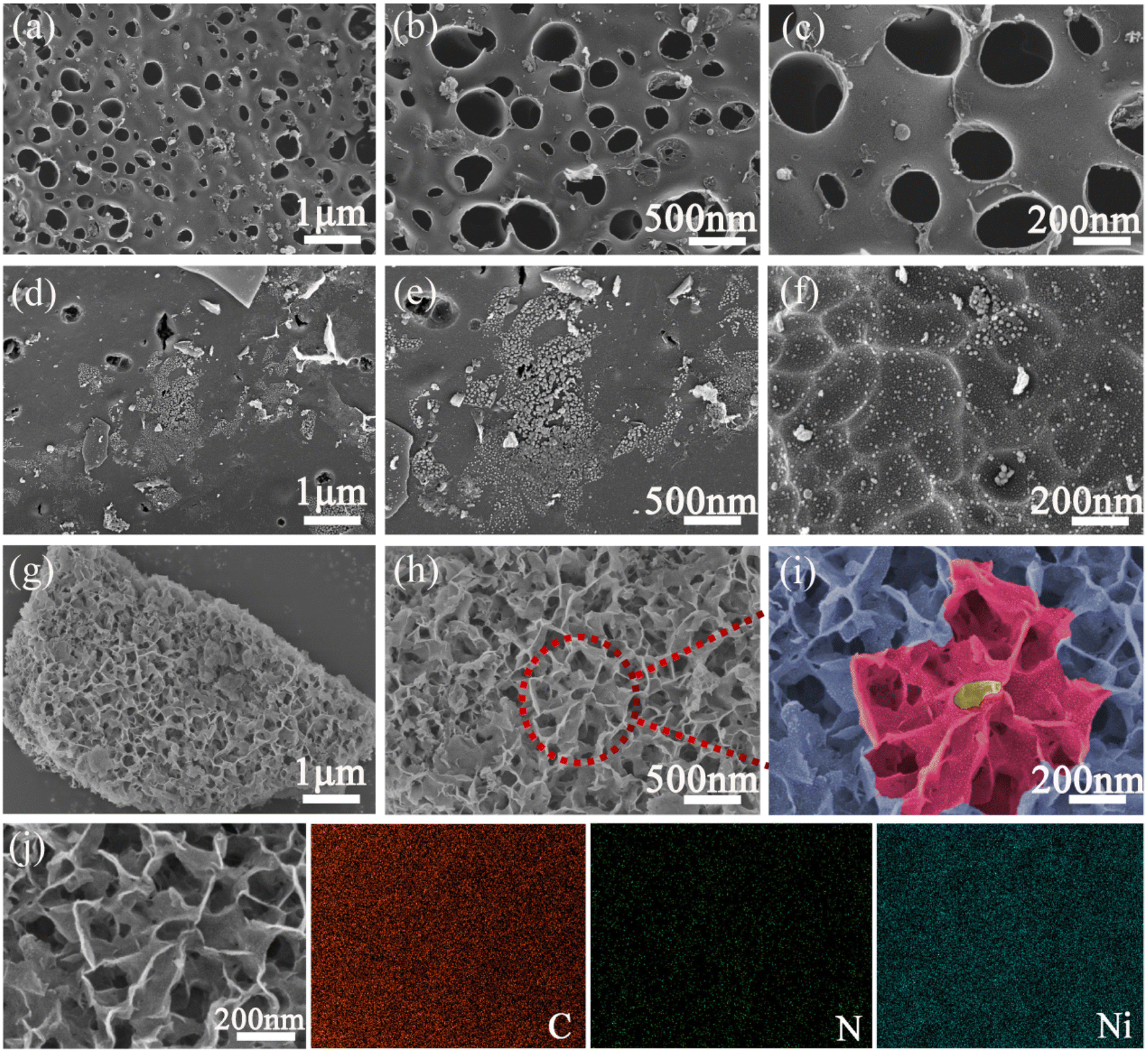 | ||
| Fig. 2 SEM images of PC (a–c), Ni@PC (d–f), Ni@NPC-1.5 (g–i), and SEM mapping (j) of Ni@NPC-1.5. | ||
Further to understand the influence of N doping on the morphology of Ni@NPC-X, morphologies at different N doping levels were studied, as shown in Fig. S3.† The structural characteristics of the Ni@NPC-1.5 composite material showed that the morphology of the composite material can be adjusted by reasonably controlling the N-doped content. The pore characteristics of PC, Ni@PC, Ni@NPC-1, Ni@NPC-1.5, and Ni@NPC-2 are represented in Fig. S4.† Carbon-based materials exhibited a large specific surface area (SBET), which enhanced the number of active sites and electrolyte contact, and thus reflecting as prospective to improve the electrochemical performance of CE.
PBP and P25 were bonded through functional groups to form a colored P25 powder. The crystal structure and composition of PBP, P25, and P25/PBP after calcination at 450 °C were analyzed by XRD and Raman spectroscopy (Fig. 3a). For P25, the diffraction peaks at 2θ = 25.27°, 37.01°, 37.70°, 38.49°, 48.11°, 53.90°, 55.11°, 62.08°, 62.71°, 68.69°, 70.30°, 74.02°, and 75.06° corresponded to the (101), (103), (004), (112), (200), (105), (211), (213), (204), (116), (220), (107), and (215) crystal planes of anatase.25 The diffraction peaks at 2θ = 27.40°, 36.11°, 39.18°, 41.19°, 44.10°, and 54.29° corresponded to (110), (101), (200), (111), (210), and (211) crystal planes of rutile.26 The diffraction peak at 2θ = 23° was attributed to the (002) crystal plane of amorphous carbon, suggesting that PBP was constructed by sintering at 450 °C is an impurity-free carbon, which was also verified from the FTIR analysis (Fig. S5a†).27 P25 and P25/PBP showed little difference in diffraction peaks, suggesting that PBP did not have a negative effect on P25 from the lattice structure level. The Raman spectroscopy analysis of PBP, P25, and P25/PBP, shown in Fig. 3b, also confirmed the same analysis results. The appearance of anatase titanium dioxide located at 143, 397, 515, and 639 cm−1, and the D and G peaks of the graphite at 1365 and 1590 cm−1 in P25 suggested the existence of P25 and C atoms in the P25/PBP composite.25
 | ||
| Fig. 3 XRD patterns (a and c) and Raman spectra (b and d). | ||
The crystal characteristics of the nitrogen-doped porous carbon-supported Ni composites (Ni@NPC-X) were investigated using XRD and Raman spectroscopy (Fig. 3c and d). The (002) and (100) planes of the typical graphitic carbon were found in all samples near 2θ = 23° and 43.5°, implying the main features of amorphous carbon.27 Compared with PC and Ni@PC without N doping, the diffraction peak of Ni@NPC-X on the (002) crystal plane was shifted, and the shift amplitude increased with the increase in the melamine proportion, which may be due to the double effect of KOH and melamine leading to more defects in the carbon-based material.28 In addition, the (111), (200), and (220) planes of Ni were also found at 2θ = 44.3°, 51.6°, and 76.2°, respectively.29 In Fig. 3d, the distinct peaks at ∼1351 cm−1 and ∼1589 cm−1 were considered to be typical D and G peaks of graphite.30 Furthermore, ID/IG of Ni@NPC-1.5 (0.99) was stronger than that of Ni@NPC-1 (0.94), and Ni@NPC-2 (0.96), indicating that the structure of Ni@NPC-1.5 had many structural defects, which resulted in the increase of electrochemically active sites and the beneficial effect of the electrolyte transport.31
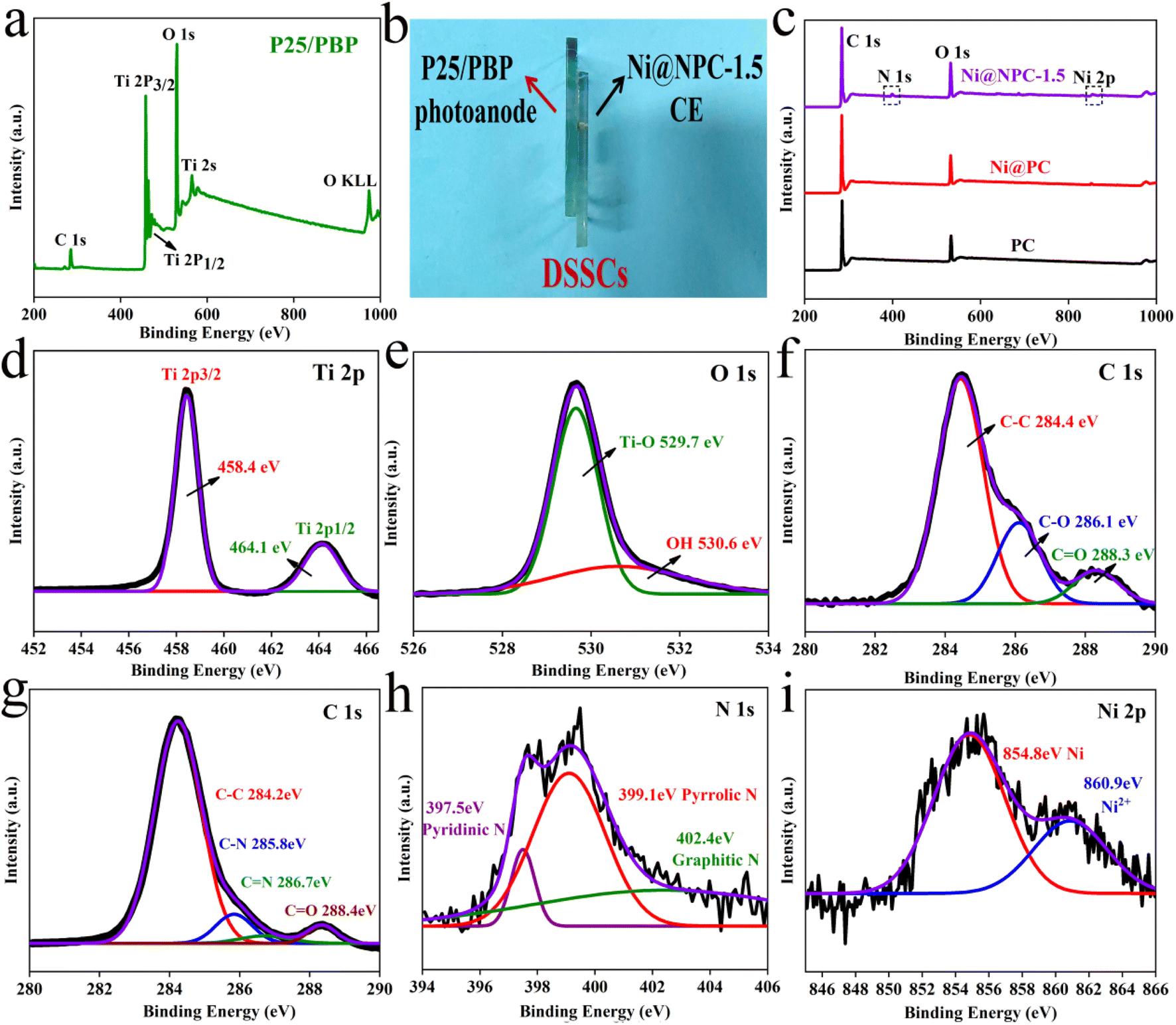
Furthermore, Fig. 4 shows the chemical composition, chemical bond properties, and bonding states of the surface elements on P25/PBP and Ni@NPC-1.5 surfaces. For P25/PBP (Fig. 4a), the presence of Ti, O, and C is supported. The high-resolution Ti 2p spectrum showed representative strong binding energy peaks at 458.4 eV and 464.1 eV ascribed to Ti 2p3/2 and Ti 2p1/2, respectively.32 The deconvolution of the high-resolution O 1s spectrum indicated peaks at 529.7 eV and 530.6 eV, due to Ti–O and OH on the Ni@NPC-1.5 surface (Fig. 4e). The high-resolution spectrum of C 1s indicated peaks at 284.4 eV, 285.6 eV, and 288.3 eV corresponding to C–C, C–O, and C![[double bond, length as m-dash]](https://www.rsc.org/images/entities/char_e001.gif) O, respectively.33,34
O, respectively.33,34
 | ||
| Fig. 4 XPS spectra of P25/PBP, Ni@PC, PC and Ni@NPC-1.5 (a–i). | ||
In particular, the full spectrum Ni@NPC-1.5 shown in Fig. 4c indicated the presence of C, N, and Ni elements, which confirmed that N was doped into the sample. The formation of N-doped PC was further illustrated by the presence of C–N and CN bonds indicated by the peaks at 285.8 eV and 286.7 eV in the high-resolution C 1s spectrum in Fig. 4g.35 Analysis of the N 1s spectrum revealed that the proportions of pyridine N, pyrrolic N, and graphitic N at 398.5, 400.5, and 402.9 eV were 8.4, 51, and 40.6%, respectively.36 The high proportion of pyridine N and pyrrole N formed in the carbon structure has the potential for electrocatalysis.37 Graphite N can improve the electrical conductivity of carbon materials, and both can play a vital role in improving the catalytic reduction performance of carbon materials.38 Moreover, as shown in Fig. 4i, the characteristic peak at 854.8 eV for the high-resolution Ni 2p belongs to metallic Ni, which provides the basis for that Ni(CH3COO)2·4H2O was carbo-thermally reduced to Ni monomers.39 The trace Ni2+ with the characteristic peak at 860.9 eV may be caused by the surface oxidation in the air.
3.2 Performance of DSSCs assembled using P25/PBP and Pt
The fabricated DSSCs of P25-Pt, P25/PBP-Pt, P25/PBP-1-Pt, P25/PBP-2-Pt, and P25/PBP-3-Pt were tested under 1 sun condition with 0.25 cm2. As shown in Table 1 and Fig. 5, the analysis results of the J–V curve showed that the descending order of PCE was P25/PBP-Pt (5.82%) > P25/PBP-2-Pt (5.63%) > P25/PBP-1-Pt (5.46%) > P25-Pt (4.96%) > P25/PBP-3-Pt (4.11%) (Fig. 5a). P25/PBP-Pt showed the highest PCE, which is better than pure P25-Pt. The open circuit voltage (Voc) was 0.71 V for both P25/PBP-Pt and P25-Pt, and the fill factor (FF) increased with the addition of PBP, possibly due to the better conductivity of carbon materials.40 The Jsc of P25/PBP-Pt (14.66 mA cm−2) was 13.3% higher than that of P25-Pt (12.94 mA cm−2), which enhanced the performance of P25/PBP-Pt. The addition of PBP played a positive role in the enhancement of photocurrent, which was also reflected in PCE. The addition of PBP increased the optical absorbance of P25/PBP in the visible region (supported by Fig. S5b†). The Nyquist plots (Fig. 5b) and Bode plots (Fig. 5c) of DSSCs fabricated at different contents of PBP, and J–V curves (Fig. 5d) of P25-Pt and P25/PBP-Pt further confirmed the effect of PBP on the PCE enhancement.| DSSCs | Voc (V) | Jsc (mA cm−2) | FF | PCE (%) | Rs (Ω) | Rct (Ω) | fmax (Hz) |
|---|---|---|---|---|---|---|---|
| a Voc: open-circuit voltage, Jsc: short-circuit current density, FF: fill factor, PCE: power conversion efficiency, Rs: volume resistance, Rct: charge-transfer resistance. | |||||||
| P25-Pt | 0.71 ± 0.01 | 12.94 ± 0.2 | 0.54 ± 0.01 | 4.96 ± 0.08 | 23.1 | 83.9 | 12.10 |
| P25/PBP-Pt | 0.71 ± 0.01 | 14.66 ± 0.1 | 0.56 ± 0.01 | 5.82 ± 0.08 | 21.6 | 76.8 | 5.63 |
| P25/PBP-1-Pt | 0.71 ± 0.01 | 12.62 ± 0.2 | 0.61 ± 0.01 | 5.46 ± 0.02 | 21.0 | 86.9 | 8.06 |
| P25/PBP-2-Pt | 0.67 ± 0.01 | 13.56 ± 0.2 | 0.62 ± 0.01 | 5.63 ± 0.06 | 23.5 | 78.7 | 6.62 |
| P25/PBP-3-Pt | 0.72 ± 0.01 | 8.38 ± 0.3 | 0.68 ± 0.01 | 4.11 ± 0.08 | 23.7 | 100.7 | 8.46 |
 | ||
| Fig. 5 J–V curves (a), Nyquist plots (b), and Bode plots (c) of DSSCs assembled with different contents of PBP; J–V curves (d), Nyquist plots (e), Bode plots (f), dark current diagrams (g), V–T curves (h), UV-vis absorption spectra (i) of P25/PBP and P25. | ||
EIS-curve analysis was adopted as a more comprehensive understanding of the relationship and underlying reasons between the introduction of PBP and the enhancement of optoelectronic properties (Fig. 5e). Rs and R1 between the electrolyte/CE interfaces of P25/PBP-Pt and P25-Pt were approximately the same,41 due to the use of Pt CEs. The main difference is that the Rct between the TiO2/dye/electrolyte interfaces (76.8 Ω) of P25/PBP-Pt was less than P25-Pt (83.9 Ω), which meant that P25/PBP-Pt had better electron transfer ability.42 This is beneficial to substantially increase the PCE of DSSCs.
Fig. 5f depicts the Bode plots of P25/PBP-Pt and P25-Pt. Compared with ∼12.1 Hz for P25-PT, the fmax value for P25/PP-PT had a beneficial decrease (∼5.63 Hz). According to the electronic lifetime calculation formula: τn = 1/2πfmax,43 it can be seen that P25/PBP-Pt had a larger τn and a faster electron transfer ability. This result indicates that the addition of PBP has a positive effect on accelerating the electron transfer ability of the P25 photoanode.
Dark current and OCVD tests and analyses are necessary to study the effect of adding PBP on the electron lifetime. Fig. 5g shows the J–V curve of P25/PBP-Pt and P25-Pt under dark condition. Under the additional voltage, P25/PBP-Pt showed a lower dark current, indicating that the dark reaction and the hole–electron recombination of P25/PBP-Pt were small. As can be seen from the OCVD curve in Fig. 5h, the voltage decay rate of P25/PBP-Pt was slower while the light source was removed. As shown in the τn–V curves in the inset of Fig. 5h, in the voltage range of 0–0.7 V, the τn of the P25/PBP-Pt is greater than that of P25-Pt.44
Furthermore, as shown in Fig. 5i, the UV-vis absorptions of the photoanode after the dye adsorption on P25/PBP and P25 with similar thickness were tested. Both P25/PBP and P25 showed strong absorption peaks at 550 nm in the visible region of 300–800 nm, corresponding to the main absorption peak of N719 dye. The absorbance of P25/PBP at the maximum absorption peak was 6.8% higher than that of P25. This result showed that the addition of PBP enhanced the absorption capacity of P25/PBP to N719 dye, thereby, increasing Jsc. Using 0.5 M NaOH to analyze the content of N719 dye loaded on the photoanode, the loading of the P25/PBP (15.3 × 10⁻⁸ mol cm−2) was greater than that of P25 (16.8 × 10⁻⁸ mol cm−2).
The electrochemical stability of DSSCs assembled with P25/PBP photoanode and Pt CE was measured under simulated illumination in the I−/I3− electrolyte for 72 h against the P25 photoanode. As shown in Fig. 6, the Voc and Jsc of the DSSCs based on the P25 photoanode continued to decrease after the test, resulting in a decrease in the PCE value from the initial value of 4.96% to 2.8%, and the decay rate reached 43.5%. For DSSCs assembled with the P25/PBP photoanode, Voc decreased from 0.71 V to 0.68 V, Jsc decreased from 14.66 mA cm−2 to 12.21 mA cm−2, and the PCE decay rate was only 28.7% with the initial value of 5.82%; the decay rate of P25/PBP photoanode was lower than that of the P25 photoanode. PBP not only increased the adsorption of dyes on the photoanode but also effectively inhibited the decay of DSSCs to a certain extent, providing a sustainable and stable capacity.
 | ||
| Fig. 6 The electrochemical stability of DSSCs based on P25 and P25/PBP photoanode. | ||
3.3 Performance of DSSCs assembled by P25/PBP and Ni@NPC-X
Nitrogen-doped porous carbon-covered Ni composites (Ni@NPC) were strategically prepared by using the natural three-dimensional network structure of biomass-based carbon as a carrier and introducing Ni nanoparticles to reduce the agglomeration of metal particles. Therefore, the comprehensive performance of the DSSCs assembled with Ni@NPC as the counter electrode and P25/PBP as the photoanode was evaluated.Fig. 7a shows the J–V curves of the DSSCs assembled with P25/PBP and Ni@NPC-X. Fig. 7b shows the schematic of the assembled DSSCs of the P25/PBP photoanode and Ni@NPC-X CEs. The relevant PV evaluation indexes are represented in Tables 2 and S1.† The PCE of Ni@PC-based DSSCs (2.94%) is greater than that of PC-based DSSCs (1.86%), reflecting the enhanced catalytic reduction ability of PC for I3− after Ni addition. In addition, DSSCs based on N-doped Ni@NPC-X CEs have significantly improved the photovoltaic performance compared to that showed by PC and Ni@PC, and showed an enhanced effect in the catalytic reduction of I3−. With the increase in the N doping content, the FF values from Ni@NPC-1 to Ni@NPC-1.5 gradually increased, and the increase in the FF value promoted the improvement in the PCE values. The addition of excessive melamine reduces the SBET, resulting in the reduction of the surface contact between the electrolyte and electrode and the increase of the internal resistance of the electron transmission, which is reflected in the decrease of FF value at Ni@NPC-2. Correspondingly, the PCE of Ni@NPC-X (X = 0, 1, and 1.5) CEs has a certain relationship with the amount of N doping, which changes from an increasing trend to decreasing trend, that is, when the N doping amount reaches 2 g, the PCE decreased. Only when the amount of N doping is appropriate, the PCE of Ni@NPC-1.5 is the highest, reaching 4.86%, with Voc of 0.70 V, Jsc of 11.17 mA cm−2, and FF of 0.62.
 | ||
| Fig. 7 J–V curves (a), schematic of the assembled DSSCs of P25/PBP photoanode and Ni@NPC-X CEs (b), CV curves (c and d) of Ni@PC, Ni@NPC-X, Pt, and PC at 50 mV s−1. | ||
| CEs | Vov (V) | Jsc (mA cm−2) | FF | PCE (%) | Ep (mV) | Ip (mA cm−2) | Rct (Ω) | Rs1 (Ω) |
|---|---|---|---|---|---|---|---|---|
| a Ip: current density of cathode peak, Ep: difference of REDOX peaks, Rct: charge transfer resistance, Rs1: series resistance. | ||||||||
| PC | 0.63 ± 0.01 | 8.93 ± 0.2 | 0.33 ± 0.01 | 1.86 ± 0.02 | 882 | −4.83 | 13.61 | 20.67 |
| Ni@PC | 0.68 ± 0.01 | 8.49 ± 0.4 | 0.51 ± 0.02 | 2.94 ± 0.04 | 742 | −6.02 | 9.82 | 22.96 |
| Ni@NPC-1 | 0.72 ± 0.01 | 9.49 ± 0.2 | 0.55 ± 0.01 | 3.88 ± 0.05 | 682 | −6.50 | 5.39 | 16.67 |
| Ni@NPC-1.5 | 0.70 ± 0.01 | 11.17 ± 0.4 | 0.62 ± 0.02 | 4.86 ± 0.08 | 628 | −8.50 | 3.02 | 20.09 |
| Ni@NPC-2 | 0.67 ± 0.01 | 9.13 ± 0.5 | 0.49 ± 0.02 | 2.99 ± 0.05 | 721 | −7.83 | 7.08 | 17.53 |
| Pt | 0.71 ± 0.01 | 14.66 ± 0.1 | 0.56 ± 0.01 | 5.82 ± 0.08 | 588 | −6.15 | 4.91 | 17.29 |
The electrocatalytic activity and I3− reduction reversibility of PC, Ni@NPC-X, and Pt CEs were studied from CV curves, and the photovoltaic performance differences of different CEs-based DSSCs were evaluated.45 The CV curves of CEs at 50 mV s−1 are illustrated in Fig. 7c and d. Notably, Ni@NPC-X has a much larger background current density than PC, Ni@PC, and Pt due to the increase of vacancy defects in the N-doped composites and the effective adsorption of I3− ions at the defect sites, which is beneficial for the generation of double capacitance.46 It can be seen that in all composite materials CEs, the Ip values vary from high to low, following Ip(Ni@NPC-1.5: 8.5 mA cm−2) > Ip(Ni@NPC-2: 7.83 mA cm−2) > Ip(Ni@NPC-1: 6.5 mA cm−2) > Ip(Ni@PC: 6.02 mA cm−2) > Ip(PC: 4.83 mA cm−2), which is the basis for the highest electrocatalytic activity of Ni@NPC-1.5.47 The order of ΔEp values varying from low to high is ΔEp(Ni@NPC-1.5: 628 mV) < ΔEp(Ni@NPC-1: 682 mV) < ΔEp(Ni@NPC-2: 721 mV) < ΔEp(Ni@PC: 742 mV) < ΔEp(PC: 882 mV), showing that the increase of reaction power speed leads to the decrease of ΔEp value.48 The higher Ip and smaller ΔEp value of Ni@NPC-1.5 comprehensively reflect its superiority in catalytic reduction of I3−. The reason may lie in the enhancement of the specific surface area of the vacancy defect sites and carbon-based materials by N doping, promoting the adsorption of electrolytes and accelerating the transfer of charge, which are beneficial to the realization of high electrocatalysis during the catalytic reduction of I3− and fast reaction kinetics.
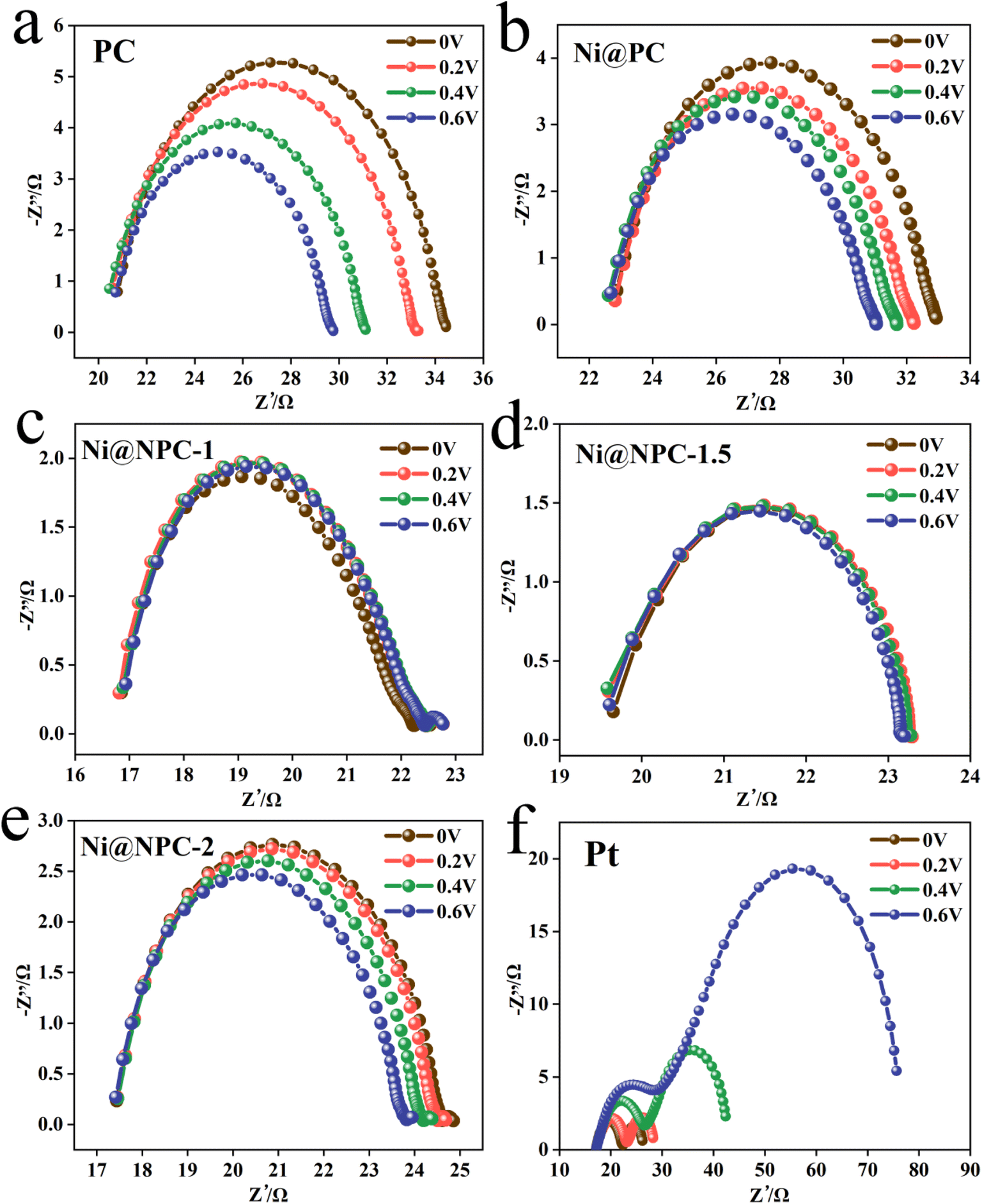
Analysis of the Nyquist plots of symmetric cells assembled based on the same CE is essential to further explain the difference in key properties of DSSCs constructed from different CEs (Fig. 8a and 9).49 The schematic diagram of the symmetrical cell assembled based on Ni@NPC-X CE is shown in Fig. 8b. In fact, the Rs1 value of all CEs is close to that of Pt, concentrated between 16–23 Ω, indicating that the prepared CEs material has good adhesion to conductive glass. Notably, Ni@NPC-X exhibited a low Rct of 3–8 Ω, in contrast to PC (13.61 Ω) and Ni@PC (9.82 Ω), which also implied that N doping enhanced the well-being of I3− reduction through good electrocatalytic activity. As shown in Fig. 8d, the excellent electrocatalytic performance of the three-dimensional network structure of multiple defect sites provided by the N-doped biochar cooperates with Ni metal ions. Therefore, the proper N-doped Ni@NPC-1.5 has the lowest Rct of 3.02 Ω, which is even lower than that of Pt (4.91 Ω). Ni@NPC-1.5 with low Rct has a higher PCE that is closer to that of Pt, which corresponds to the Rct and PCE curves shown in Fig. 8c.
 | ||
| Fig. 8 Nyquist plots (a) of PC, Ni@PC, Ni@NPC-X, and Pt under a bias voltage of 0 V based on the symmetrical cells, Schematic diagram of a symmetrical cell assembled based on Ni@NPC-X CE (b), PCE and Rct values (c), schematic of Ni@NPC-X CE reduction I3− (d). | ||
 | ||
| Fig. 9 Nyquist plots at various bias voltages. | ||
Fig. S7† represents the Tafel polarization curves of symmetric cells assembled by the various CEs, which are mainly adopted to explain the relationship between the over-potential voltage (V) and the logarithmic current density (logJ). The exchange current density (J0) (0.002 mA cm−2) of the Ni@NPC-1.5 composite was greater than that of PC (0.00093 mA cm−2), Ni@PC (0.001 mA cm−2), Ni@NPC-1 (0.0014 mA cm−2) and Ni@NPC-2 (0.00128 mA cm−2) and Pt (0.0015 mA cm−2), indicating that Ni@NPC-1.5 has good electrocatalysis on I3− reduction.50 According to eqn (1), the result of the Jo value is also consistent with the changing trend of Rct in the Nyquist plots.
 | (1) |
In addition, the limiting diffusion current density (Jlim) value of the Ni@NPC-1.5 composite material is also greater than that of other CE materials. According to eqn (2), it can be confirmed that the surface between the I3− ion in the electrolyte and Ni@NPC-1.5 has a larger diffusion coefficient (D).
 | (2) |
The strong diffusion coefficient of the as-prepared composite CEs is mainly due to the great SBET and mesoporous pores, which is conducive to the diffusion of I3− ions and the contribution of N doping is that the provision of a large number of defect sites, contributes to the increase in charge transfer, which ultimately ensures the electrocatalytic activity of Ni@NPC-1.5 for reducing I3− ions.
To more intuitively evaluate the photovoltaic performance of the biomass-blueberry composites as CEs for DSSCs, the PCE values of other biomass-derived carbons were compared. As shown in Table 3, the PCE value (4.86%) of the blueberry-based CEs assembly was higher than or not significantly different from that previously reported for biomass carbon-based CEs (PCE = 1.89–5.54%). In this experiment, through the synergistic effect of KOH activation and melamine, the specific surface area of the blueberry carbon-based material was increased, making it exhibit excellent electrocatalytic activity.
| Biomass carbon CE | Voc (V) | Jsc (mA cm−2) | FF | PCE (%) | PCE (Pt) (%) | SBET (m2 g−1) | ||
|---|---|---|---|---|---|---|---|---|
| Aloe peel51 | 0.68 | 13.25 | 0.58 | 5.20 | 6.46 | — | ||
| Pomelo peel52 | 0.67 | 13.40 | 0.53 | 4.45 | 6.71 | 534.45 | ||
| Chitin53 | 0.69 | 11.33 | 0.61 | 4.81 | 6.30 | 359.7 | ||
| Poplar54 | 0.62 | 12.15 | 0.24 | 1.89 | 6.23 | 272.8 | ||
| Rice husk55 | 0.67 | 13.97 | 0.59 | 5.54 | 6.32 | 268.7 | ||
| Bagasse56 | 0.69 | 10.70 | 0.37 | 2.48 | 6.08 | — | ||
| Waste carton57 | 0.65 | 11.69 | 0.60 | 6.19 | 7.51 | 655.36 | ||
| Blueberry (this work) | 0.70 | 10.77 | 0.63 | 4.86 | 5.84 | 1185.7 | ||
3.4 Analysis of the electrochemical performance of Ni@NPC-1.5
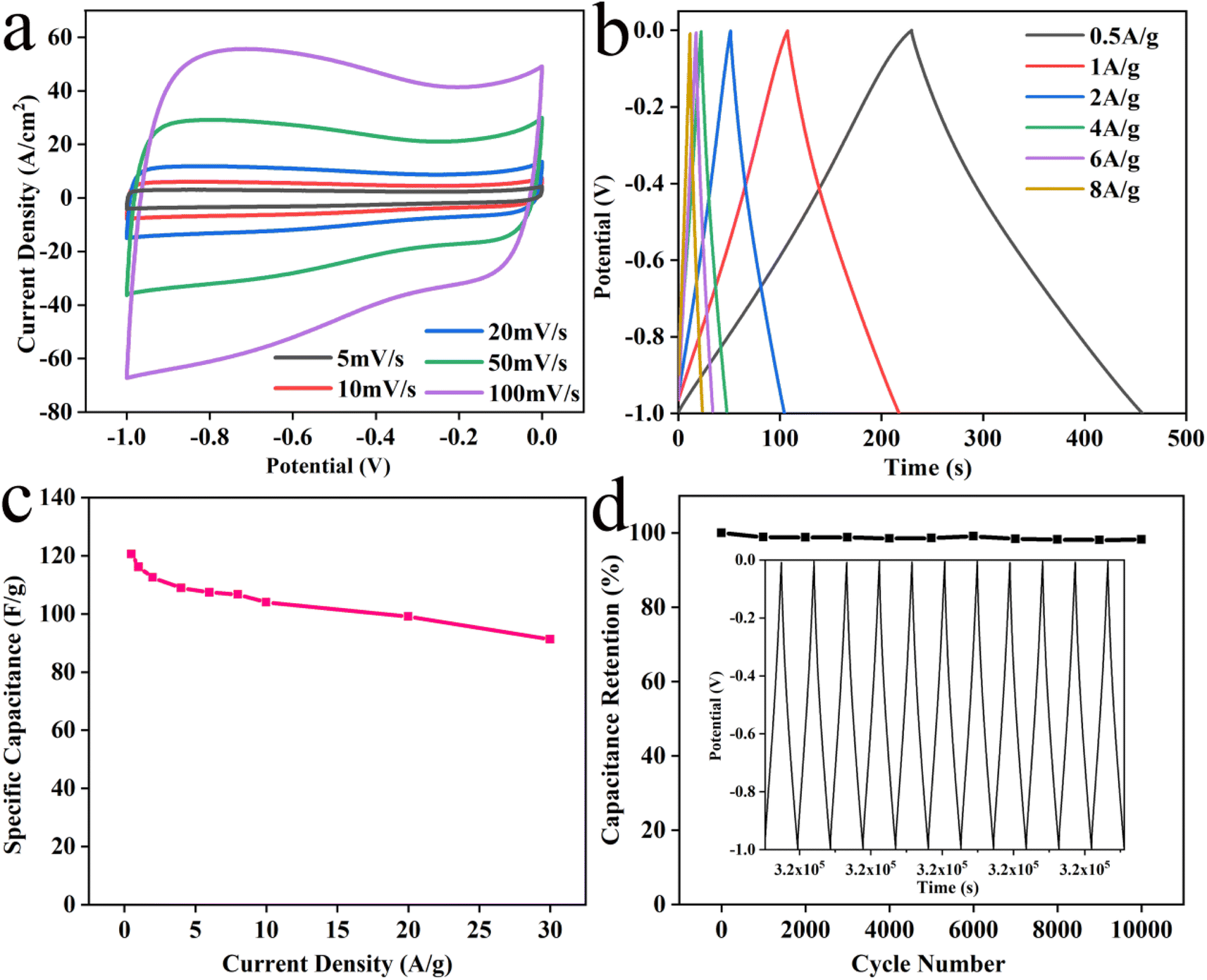
Ni@NPC-1.5 exhibits a nearly rectangular and well-symmetrical CV curve even with an increased scan rate (Fig. 10a). As can be seen from Fig. 10b, the potential varies linearly with time and has a symmetrical triangle shape. Observing the GCD curve, almost no voltage drop was observed, indicating that the electrode has a low internal resistance, can be charged/discharged quickly, and has good rate performance. The specific capacitance of Ni@NPC-1.5 is 120.55, 116.12, 112.46, 108.88, 107.37, 106.66, 103.94, 99.02, and 91.27 F g−1 at 0.5, 1, 2, 4, 6, 8, 10, 20 and 30 A g−1, respectively (Fig. 10c). The cycling stability shown in Fig. 10d represents a good capacitance retention of 98.2% after 10000 cycles. So, the above analysis further provides a basis for supporting the good electrochemical stability and reversibility of Ni@NPC-1.5 from an electrochemical point of view.
 | ||
| Fig. 10 CV curves (a) of Ni@NPC-1.5, GCD curves (b), specific capacitance values (c), cycling performance for the Ni@NPC-1.5 at 6 A g−1 over 10000 cycles (d). | ||
4 Conclusions
In the current work, the P25/blueberry anthocyanin (P25/PBP, photoanode) composite material and the blueberry-derived N-doped porous carbon-loaded Ni nanoparticle composite material (Ni@NPC-X, CE) served as two functional electrodes for the fabrication of blueberry-based DSSCs and their characteristics and performance were evaluated. When the masses of anthocyanins introduced into P25 were 0.025 g, 0.05 g, 0.1 g, and 0.2 g, different PCE values of 5.46%, 5.82%, 5.63%, and 4.11%, respectively, were observed. Among them, the PCE was the highest (5.82%) with the addition of 0.05 g of anthocyanin, which is higher than that with pure P25 (4.96%). According to electrochemical and UV-visible results, the combination of PBP and TiO2 reduces charge recombination and improves the dye adsorption capacity of the photoanode. In addition, by adding 1 g, 1.5 g, and 2 g of melamine, N-doped porous carbon materials loaded Ni nanoparticle composites (Ni@NPC-1, Ni@NPC-1.5, and Ni@NPC-2) were constructed. Melamine changes the microscopic morphology of bio-based materials into petals and increases the SBET. In the Ni@NPC-X composite, PC with a porous three-dimensional network structure was used as the electrocatalytic Ni carrier material to reduce the agglomeration of Ni nanoparticles. Ni@NPC-1.5 showed excellent electron transfer ability in electrochemistry with a lower Rct of 3.02 Ω than that of Pt (Rct of 4.91 Ω). The PCE values of the DSSCs fabricated by Ni@NPC-1, Ni@NPC-1.5, and Ni@NPC-2 composite materials as the counter electrode and P25/PBP as the photoanode were 3.88%, 4.86%, and 2.99%, respectively. Among them, the PCE of DSSCs with Ni@NPC-1.5 as CE (4.86%) was the highest close to that of Pt as CE (5.82%). Moreover, from an electrochemical point of view, it provides the basis for supporting the good electrochemical stability and reversibility of Ni@NPC-1.5. The reported blueberry electrode material not only improved the electrochemical performance of the photoanode but also showed a performance close to that of Pt as the counter electrode, which provided new ideas for blueberries-based photovoltaic-electric energy systems for DSSCs.Conflicts of interest
There are no conflicts to declare.Acknowledgements
This work was supported by the Innovation Project of Guangxi Graduate Education (YCSW2022003), the National Innovation and Entrepreneurship Training Plan for College Students of Guangxi University (202110593103), and the National Natural Science Foundation of China (Grants No. 31960293).References
- B. Li, L. Wang, B. Kang, P. Wang and Y. Qiu, Sol. Energy Mater. Sol. Cells, 2006, 90, 549–573 CrossRef CAS
.
- M. Feng, S. You, N. Cheng and J. Du, Electrochim. Acta, 2019, 293, 356–363 CrossRef CAS
- W. Yang, Y. Yao, P. Guo, H. Sun and Y. Luo, Phys. Chem. Chem. Phys., 2018, 20, 29866–29875 RSC
- J. Wu, Z. Lan, J. Lin, M. Huang, Y. Huang, L. Fan, G. Luo, Y. Lin, Y. Xie and Y. Wei, Chem. Soc. Rev., 2017, 46, 5975–6023 RSC
- J. M. K. W. Kumari, G. K. R. Senadeera, M. A. K. L. Dissanayake and C. A. Thotawatthage, Ionics, 2017, 23, 2895–2900 CrossRef CAS
- Y. Jo, J. Y. Cheon, J. Yu, H. Y. Jeong, C. H. Han, Y. Jun and S. H. Joo, Chem. Commun., 2012, 48, 8057–8059 RSC
- J. Zhou, L. Chen, Y. Wang, Y. He, X. Pan and E. Xie, Nanoscale, 2016, 8, 50–73 RSC
- P. Makal and D. Das, Mater. Chem. Phys., 2021, 266, 124520 CrossRef CAS
- N. Gao, T. Wan, Z. Xu, L. Ma, S. Ramakrishna and Y. Liu, Mater. Chem. Phys., 2020, 255, 123542 CrossRef CAS
- J. Wang, X. Nie, W. Wang, Z. Zhao, L. Li and Z. Zhang, Optik, 2021, 242, 167245 CrossRef CAS
- D. Lu, L. Qin, D. Liu, P. Sun, F. Liu and G. Lu, Electrochim. Acta, 2018, 292, 180–189 CrossRef CAS
- I. Ahmad, R. Jafer, S. M. Abbas, N. Ahmad, R. Ata ur, J. Iqbal, S. Bashir, A. A. Melaibari and M. H. Khan, J. Alloys Compd., 2022, 891, 162040 CrossRef CAS
- T. Alizadeh, F. Zargar and M. R. Zamanloo, J. Mater. Sci.: Mater. Electron., 2019, 30, 7981–7991 CrossRef CAS
- M. Batmunkh, M. Dadkhah, C. J. Shearer, M. J. Biggs and J. G. Shapter, Appl. Surf. Sci., 2016, 387, 690–697 CrossRef CAS
- P. Zhang, C. L. Shao, Z. Y. Zhang, M. Y. Zhang, J. B. Mu, Z. C. Guo and Y. C. Liu, Nanoscale, 2011, 3, 2943–2949 RSC
- S. N. Yun, Y. W. Zhang, Q. Xu, J. M. Liu and Y. Qin, Nano Energy, 2019, 60, 600–619 CrossRef CAS
- G. T. Yue, L. Wang, X. A. Zhang, J. H. Wu, Q. W. Jiang, W. F. Zhang, M. L. Huang and J. M. Lin, Energy, 2014, 67, 460–467 CrossRef CAS
- Y. Zhang, Y. Jiao, M. Liao, B. Wang and H. Peng, Carbon, 2017, 124, 79–88 CrossRef CAS
- H. M. Chuang, C. T. Li, M. H. Yeh, C. P. Lee, R. Vittal and K.-C. Ho, J. Mater. Chem. A, 2014, 2, 5816–5824 RSC
- R. Tas, M. Can and S. Sonmezoglu, IEEE J. Photovolt., 2017, 7, 792–801 Search PubMed
- W. Hou, Y. Xiao and G. Han, Angew. Chem., Int. Ed., 2017, 56, 9146–9150 CrossRef CAS PubMed
- J. Li, S. Yun, F. Han, Y. Si, A. Arshad, Y. Zhang, B. Chidambaram, N. Zafar and X. Qiao, J. Colloid Interface Sci., 2020, 578, 184–194 CrossRef CAS PubMed
- A. A. Qureshi, S. Javed, H. M. Asif Javed, A. Akram, M. Jamshaid and A. Shaheen, Opt. Mater., 2020, 109, 110267 CrossRef CAS
- J. Qiu, D. He, H. Wang, W. Li, B. Sun, Y. Ma, X. Lu and C. Wang, Electrochim. Acta, 2021, 367, 137451 CrossRef CAS
- T. K. Das, P. Ilaiyaraja and C. Sudakar, Sol. Energy, 2018, 159, 920–929 CrossRef CAS
- Z. Shen, G. Wang, H. Tian, J. Sunarso, L. Liu, J. Liu and S. Liu, Electrochim. Acta, 2016, 216, 429–437 CrossRef CAS
- B. Yu, A. Gele and L. Wang, Int. J. Biol. Macromol., 2018, 118, 478–484 CrossRef CAS
- K. Zou, Y. Deng, J. Chen, Y. Qian, Y. Yang, Y. Li and G. Chen, J. Power Sources, 2018, 378, 579–588 CrossRef CAS
- Y. Liu, X. Li, Y. Li, Z. Zhao and F. Bai, Appl. Phys. A, 2016, 122, 174 CrossRef
- Y. Shang, X. Liu, J. Zhang, C. Lu and C. Zhang, Ionics, 2021, 27, 1967–1976 CrossRef CAS
- K. Mi, S. Chen, B. Xi, S. Kai, Y. Jiang, J. Feng, Y. Qian and S. Xiong, Adv. Funct. Mater., 2017, 27, 1604265 CrossRef
- B. Chai, T. Peng, P. Zeng and J. Mao, J. Mater. Chem., 2011, 21, 14587 RSC
- R. Yuan, H. Wen, L. Zeng, X. Li, X. Liu and C. Zhang, Nanomaterials, 2021, 11, 694 CrossRef CAS PubMed
- Q. Wu, W. Li, J. Tan, Y. Wu and S. Liu, Chem. Eng. J., 2015, 266, 112–120 CrossRef CAS
- Y. Zhao, J. Shen, Z. Yu, M. Hu, C. Liu, J. Fan, H. Han, A. Hagfeldt, M. Wang and L. Sun, J. Mater. Chem. A, 2019, 7, 12808–12814 RSC
- W. M. Yin, L. F. Tian, B. Pang, Y. R. Guo, S. J. Li and Q. J. Pan, Int. J. Biol. Macromol., 2020, 156, 988–996 CrossRef CAS PubMed
- A. Shrestha, M. Batmunkh, C. J. Shearer, Y. Yin, G. G. Andersson, J. G. Shapter, S. Qiao and S. Dai, Adv. Energy Mater., 2016, 7, 1602276 CrossRef
- S. M. Li, S. Y. Yang, Y. S. Wang, H. P. Tsai, H. W. Tien, S. T. Hsiao, W. H. Liao, C. L. Chang, C. C. M. Ma and C. C. Hu, J. Power Sources, 2015, 278, 218–229 CrossRef CAS
- G. Kyriakou, A. M. Márquez, J. P. Holgado, M. J. Taylor, A. E. H. Wheatley, J. P. Mehta, A. E. Fraser, J. Fernández Sanz, S. K. Beaumont and R. M. Lambert, ACS Catal., 2019, 9, 9310–9310 CrossRef CAS
- R. Ghayoor, A. Keshavarz, M. N. S. Rad and A. Mashreghi, Mater. Res. Express, 2018, 6, 025505 CrossRef
- A. Hegazy, N. Kinadjian, B. Sadeghimakki, S. Sivoththaman, N. K. Allam and E. Prouzet, Sol. Energy Mater. Sol. Cells, 2016, 153, 108–116 CrossRef CAS
- U. Mehmood, M. Zaheer Aslam, R. A. Shawabkeh, I. A. Hussein, W. Ahmad and A. G. Rana, IEEE J. Photovolt., 2016, 6, 1191–1195 Search PubMed
- L. Chen, X. Li, Y. Wang, C. Gao, H. Zhang, B. Zhao, F. Teng, J. Zhou, Z. Zhang, X. Pan and E. Xie, J. Power Sources, 2014, 272, 886–894 CrossRef CAS
- A. Zaban, M. Greenshtein and J. Bisquert, Chemphyschem, 2003, 4, 859–864 CrossRef CAS PubMed
- X. Wang, S. Wang, Y. Xie, Y. Jiao, J. Liu, X. Wang, W. Zhou, Z. Xing and K. Pan, ACS Sustainable Chem. Eng., 2019, 7, 14353–14360 CrossRef CAS
- M. Chen, L.-L. Shao, X.-W. Lv, G.-C. Wang, W.-Q. Yang, Z.-Y. Yuan, X. Qian, Y.-Y. Han and A.-X. Ding, Chem. Eng. J., 2020, 390, 124633 CrossRef CAS
- T. Zhang, S. Yun, X. Li, X. Huang, Y. Hou, Y. Liu, J. Li, X. Zhou and W. Fang, J. Power Sources, 2017, 340, 325–336 CrossRef CAS
- X. Cui, J. Xiao, Y. Wu, P. Du, R. Si, H. Yang, H. Tian, J. Li, W. H. Zhang, D. Deng and X. Bao, Angew. Chem., Int. Ed., 2016, 55, 6708–6712 CrossRef CAS PubMed
- M. Chen, G. C. Wang, L.-L. Shao, Z.-Y. Yuan, X. Qian, Q.-S. Jing, Z.-Y. Huang, D.-L. Xu and S.-X. Yang, ACS Appl. Mater. Interfaces, 2018, 10, 31208–31224 CrossRef CAS PubMed
- Y. J. Huang, Y. J. Lin, H. J. Chien, Y. F. Lin and K. C. Ho, Nanoscale, 2019, 11, 12507–12516 RSC
- Y. Zhang, S. Yun, C. Wang, Z. Wang, F. Han and Y. Si, J. Power Sources, 2019, 423, 339–348 CrossRef CAS
- Z. Li, L. Zhang, B. S. Amirkhiz, X. Tan, Z. Xu, H. Wang, B. C. Olsen, C. M. B. Holt and D. Mitlin, Adv. Energy Mater., 2012, 2, 431–437 CrossRef CAS
- Y. Di, Z. Xiao, X. Yan, G. Ru, B. Chen and J. Feng, Appl. Surf. Sci., 2018, 441, 807–815 CrossRef CAS
- S. Xu, C. Liu and J. Wiezorek, Mater. Chem. Phys., 2018, 204, 294–304 CrossRef CAS
- G. Wang, D. Wang, S. Kuang, W. Xing and S. Zhuo, Energy, 2014, 63, 708–714 CAS
- C. Xiang, T. Lv, C. A. Okonkwo, M. Zhang, L. Jia and W. Xia, J. Electrochem. Soc., 2017, 164, H203–H210 CrossRef CAS
- Y. Zhang, S. Yun, Z. Wang, Y. Zhang, C. Wang, A. Arshad, F. Han, Y. Si and W. Fang, Ceram. Int., 2020, 46, 15812–15821 CrossRef CAS
Footnotes |
| † Electronic supplementary information (ESI) available. See DOI: https://doi.org/10.1039/d3ra00545c |
| ‡ These authors contributed equally to this work. |
| This journal is © The Royal Society of Chemistry 2023 |