 Open Access Article
An overview of atmospheric water harvesting methods, the inevitable path of the future in water supply
Zahra Ahrestani ab,
Sadegh Sadeghzadeh
 *c and
Hosein Banna Motejadded Emrooz
 d
d
aMSc of Chemistry and Materials Technologie, Institute of Materials Chemistry, Faculty of Chemistry, University of Vienna, Vienna, Austria
bMSc of NanoTechnology, School of Advanced Technologies, Iran University of Science and Technology, Tehran, Iran
cSchool of Advanced Technologies, Iran University of Science and Technology, Tehran, Iran. E-mail: sadeghzadeh@iust.ac.ir
dSchool of Advanced Technologies, Iran University of Science and Technology, Tehran, Iran
First published on 5th April 2023
Abstract
Although science has made great strides in recent years, access to fresh water remains a major challenge for humanity due to water shortage for two-thirds of the world's population. Limited access to fresh water becomes more difficult due to the lack of natural resources of water. Many of these resources are also contaminated by human activities. Many attempts have been made to harvest water from the atmosphere, and condensation systems have received much attention. One of the challenges in generation systems is the high consumption energy of the cooling feed, despite the generation of large amounts of water from the atmosphere. As other airborne contaminants condense with water vapor, the water after harvesting needs to be treated, which adds to construction and maintenance costs. Also, the need for high relative humidity in condensation systems has led scientists to find ways of atmospheric water harvesting at low relative humidity and use renewable energy sources. Sorption systems can absorb atmospheric water without the need for an energy supply and spontaneously. Desiccants such as silica gel and zeolite, due to their high affinity for water, can absorb water vapor in the air through physical or physicochemical bonding, but all of these have slow adsorption kinetics. Therefore, it takes a long time for the water harvesting cycle or they are not able to absorb water at low relative humidity, and others need a lot of energy for the water desorption phase. Metal–Organic Frameworks (MOF) are porous materials that, due to their special structure, are considered the most promising material for atmospheric water harvesting at low relative humidity. MOF-303 has been identified as the most efficient material to date and can harvest 0.7 liters of water per kilogram of MOF-303 at 10% RH and 27 °C. MOFs can harvest atmospheric water even in desert areas using only solar energy, and the water produced is drinkable and does not need to be treated. In this review, systems and methods of atmospheric water harvesting will be studied and compared and then the mechanism of adsorption and desorption in sorption systems will be discussed in detail.
1 Introduction
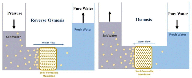
Despite the rapid growth of science, access to fresh and potable water remains a fundamental challenge for humanity. Limited access to fresh water becomes more difficult due to a lack of natural resources, such as lakes, rivers, and groundwater. Many of these resources are also contaminated by human activities.1 Water used by humans is supplied from various sources after its treatment. These sources include groundwater (aquifer), surface water (river, dam, and lake), or seas after desalination. Saltwater Oceans, seas, and groundwater make up about 97% of all water on Earth. And only 2.5% of the available water is fresh, most of it is in glaciers and the form of ice and snow in the North and South poles. There is 0.5% fresh groundwater and soil moisture, and less than 0.01% as surface water in lakes, swamps, and rivers. Freshwater lakes contain about 87% of fresh water, of which 29% is in the Great Lakes of Africa, 22% in Lake Baikal in Russia, 21% in the Great Lakes of North America, and 14% in other lakes. Air also contains 0.04% water.2 Significant increases in water consumption have led to severe water shortages in many parts of the world, and approximately 4 billion people face severe water shortages for at least one month a year.3 Climate change and the severity of drought due to changes in precipitation patterns and rising temperatures are also effective factors in reducing freshwater resources.4 In general, water scarcity is divided into two categories, physical and economic. Physical water shortages usually occur due to a lack of sufficient water resources to meet basic needs. While the lack of economic water is due to the lack of mechanisms and infrastructure to access water resources.5 Due to the freshwater crisis, there is a growing interest in the desalination process, and saltwater desalination technologies are expanding. Currently, water sources for desalination processes include seawater, groundwater, surface water, and saline wastewater.6 In areas where there is no freshwater at ground level, freshwater from rainfall may be deposited on saline groundwater due to its lower density. And can be a source of freshwater needed. When it rains, the water flowing on the ground gradually disappears and settles below the ground inside the soil and the pores in the rocks. Groundwater aquifers or aquifers are parts of the earth's crust whose holes or pores are saturated with water. Usually, the pores and holes of the rocks are filled with water due to continuous rainfall and stop there when they reach an impermeable surface like clay rocks. And is manifested in the form of various springs on the ground.7 It is estimated that eight to ten million cubic kilometers of fresh groundwater are the share of total freshwater on Earth.8 Today, due to the lack of fresh water, the importance of groundwater has increased more than before.9 On the other hand, improper use of groundwater resources, the salinity of these resources, and even industrial and agricultural pollution are among the important challenges to maintaining groundwater quality.10 Also, the formation time of groundwater aquifers is very long, and depending on the depth and other characteristics of these aquifers, they can vary from centuries to thousands of years. Therefore, survival and sustainable development in arid areas directly depend on effective management to maintain healthy quality and acceptable groundwater levels.11 Improper extraction of groundwater has led to lower groundwater levels. Also, pollutants that enter groundwater under the influence of waste washing help to disperse pollutants in an aquifer and after being infected, aquifer recovery is not easy.12 One way to compensate for water shortages is to reuse contaminated water. Water pollution varies in terms of quantity and type of pollutants based on the source of water consumption.13 In the case of domestic wastewater, such as toilet water and household cleaning water, such as washing clothes, etc., the concentration of pollutants is low compared to toilet water, and so it is called “gray water”. Toilet water, on the other hand, is highly polluted water that is rich in organic matter such as feces and urine, which contains microorganisms such as bacteria, viruses and various parasites. This water is known as “black water”.14 Gray water can be used for things like irrigating green spaces or providing moisture to greenhouses.15 Gray water usually contains some human waste and is therefore not free of pathogens. Gray water quality can deteriorate rapidly during the storage process because it is often a warm environment and contains some nutrients and organic matter (such as dead skin cells) as well as pathogens. Stored gray water also has an unpleasant odor.16 Another method of compensating for water shortages is the expansion of useable water resources. Recently, special attention has been paid to new methods and, of course, to some extent fantasy, to supply water to individuals or families and even many models have been commercialized. For example, solar water treatment is a portable solar system that provides 20![[thin space (1/6-em)]](https://www.rsc.org/images/entities/char_2009.gif) 000 liters of clean water per day.17 Or fog collection, which is very popular in mountainous areas with prolonged fog, for example on the slopes of Mount Butmusguida, which is now the largest fog harvesting project in the world. About 6300 liters of water can be harvested daily by fog collectors.18–20 “Drinkable book” is another technology made from filtered paper doped with silver nanoparticles and is offered as a portable water treatment unit in some parts of South Africa.21,22 One of the most famous technologies belongs to the life straw water filter, which with a straw can purify up to 1000 liters of water and 99.9% of parasites and bacteria filter the contaminated water and make it drinkable.23 In another method, researchers at the University of Singapore used a copper complex to produce water from the air and invented a fully intelligent solar device called a smart farm that could use the water harvested to irrigate plants daily without interference.24 Production of water from humidity based on adsorbents is another method that has been commercialized and is available from companies such as Zero Mass Water.25 Despite the breadth of different methods of water supply and purification, still, in practice, the human focus on an industrial scale is to use the reverse osmosis method. In recent years, the installation and operation of seawater desalination facilities as a tool for water supply in countries with water scarcity problems has increased. The first large-scale desalination plant was based on thermal desalination, mostly in the Persian Gulf countries. In this way, the sea water was heated and the evaporated water was condensed to produce fresh water. Such power plants, which are still operating in the Persian Gulf countries, consume significant amounts of heat and electricity, which lead to greenhouse gas emissions. The desalinators built in the last two decades are based on powerful Reverse Osmosis (RO) technology. Naturally, a low concentration solution tends to migrate to a higher concentration solution. This process is called osmosis. Reverse osmosis is an osmotic process, but in reverse. While osmosis occurs naturally without the need for energy, to reverse the osmosis process requires the use of energy for a solution with high salinity. A reverse osmosis membrane is a semi-permeable membrane that allows water molecules to pass through. It is not possible to migrate soluble salts, organic matter, bacteria. However, water must be pumped forward through the semipermeable membrane using pressure. This pressure is naturally greater than the osmotic pressure to desalinate (ionize) water in the process.26 Reverse osmosis technology has advanced significantly in the last two decades and current desalination plants can desalinate seawater with much less energy than thermal desalination.27 Fig. 1 shows the difference between the work of the reverse osmosis process and the osmosis phenomenon schematically.
000 liters of clean water per day.17 Or fog collection, which is very popular in mountainous areas with prolonged fog, for example on the slopes of Mount Butmusguida, which is now the largest fog harvesting project in the world. About 6300 liters of water can be harvested daily by fog collectors.18–20 “Drinkable book” is another technology made from filtered paper doped with silver nanoparticles and is offered as a portable water treatment unit in some parts of South Africa.21,22 One of the most famous technologies belongs to the life straw water filter, which with a straw can purify up to 1000 liters of water and 99.9% of parasites and bacteria filter the contaminated water and make it drinkable.23 In another method, researchers at the University of Singapore used a copper complex to produce water from the air and invented a fully intelligent solar device called a smart farm that could use the water harvested to irrigate plants daily without interference.24 Production of water from humidity based on adsorbents is another method that has been commercialized and is available from companies such as Zero Mass Water.25 Despite the breadth of different methods of water supply and purification, still, in practice, the human focus on an industrial scale is to use the reverse osmosis method. In recent years, the installation and operation of seawater desalination facilities as a tool for water supply in countries with water scarcity problems has increased. The first large-scale desalination plant was based on thermal desalination, mostly in the Persian Gulf countries. In this way, the sea water was heated and the evaporated water was condensed to produce fresh water. Such power plants, which are still operating in the Persian Gulf countries, consume significant amounts of heat and electricity, which lead to greenhouse gas emissions. The desalinators built in the last two decades are based on powerful Reverse Osmosis (RO) technology. Naturally, a low concentration solution tends to migrate to a higher concentration solution. This process is called osmosis. Reverse osmosis is an osmotic process, but in reverse. While osmosis occurs naturally without the need for energy, to reverse the osmosis process requires the use of energy for a solution with high salinity. A reverse osmosis membrane is a semi-permeable membrane that allows water molecules to pass through. It is not possible to migrate soluble salts, organic matter, bacteria. However, water must be pumped forward through the semipermeable membrane using pressure. This pressure is naturally greater than the osmotic pressure to desalinate (ionize) water in the process.26 Reverse osmosis technology has advanced significantly in the last two decades and current desalination plants can desalinate seawater with much less energy than thermal desalination.27 Fig. 1 shows the difference between the work of the reverse osmosis process and the osmosis phenomenon schematically.
Reverse osmosis is currently the least used technology for seawater desalination and is a benchmark for any new desalination technology. However, its adverse environmental effects can not be ignored. Desalination plants not only increase sea salt concentrations but also damage groundwater resources. To protect the environment, most countries have turned to environmental impact assessments by desalination plants. Seawater desalination plants are located along the coast to supply desalinated water to the people of the area. The construction of desalination plants will affect coastal areas. By leaking water pipes, this method can contaminate groundwater aquifers. The high concentration of salt in the brine and several chemical products used in the desalination process is returned to the sea and affects the marine ecosystem.28 The Persian Gulf is surrounded by desalination plants and about 50% of the world's seawater desalination capacity, 24 plants, is located in the Persian Gulf. Most of these plants discharge saltwater effluent into the Persian Gulf. As a result, they increase the salinity of the Persian Gulf and endanger the life of aquatic animals.29
Sadhwania et al. studied the destructive environmental impact of five desalination plants in Spain. Focusing on case studies in the Canary Islands, suggested that the effects of salt-water discharge on the marine environment could be worse in the Mediterranean than in other regions. As can be seen in the image, the brine discharge from the RO unit is directly at the coastline.28 In addition, the study of the environmental effects of seawater desalination at the outlet of a desalination plant in Bahrain showed that the temperature difference between the discharged salt water and the environment is relatively large, reaching 20 °C. The simulated temperatures in the outlet area showed that the temperature increased approximately 37 minutes after a distance of 350 m. Reaches ambient temperature and after a distance of about 390 meters, and about 41 minutes, increased salinity decreases to sea water salinity.30 Apart from the environmental damage of the desalination plants, this technology can only be used for coastal areas. As a result, landlocked and rural areas in developing countries are unable to benefit from desalination due to limited water transportation and financial and infrastructural factors. To solve the problem of water scarcity in remote areas that have neither infrastructure nor sufficient economic resources, utilization of decentralized water production systems can be one of the promising solutions.31 We have also seen an increase in natural disasters around the world in the last century. With disasters such as floods and earthquakes, local water, sewage and electricity networks are disrupted and can no longer be used. Therefore, providing safe and drinkable drinking water is a priority to prevent the spread of water-borne diseases. Delivery of drinking water through water tanks or small containers may also be delayed due to damage or road traffic. In this context, decentralized water production can also be considered. Emergency water production technology must be safe, reliable and independent of water and electricity networks to be able to use them in the affected areas.32 One of the most promising water production technologies is Atmospheric Water Harvesting (AWH). The AWH method is a reliable solution for supplying drinking water to affected, remote and poor areas. Because most decentralized methods can be used with low production costs and also solar heat can be used as an energy source.31 In this article, after a comprehensive review of past and present water supply methods, methods of harvesting water from air are reviewed and parameters affecting water harvesting from air humidity and the world's potential to produce water from humidity has been carefully studied. Condensation methods, using different cooling methods, have been considered as one of the competing methods of producing water from air humidity. The methods of physical adsorption and physico–chemical absorption are also briefly described. By reviewing different methods of water harvesting from air using advanced absorbents, metal organic frameworks were found to be one of the best options for supplying water from humidity in the future of mankind. According to studies, it has been shown that these methods can soon find a special place in providing an important part of water needed by humans.
2 Atmospheric water harvesting
As mentioned, the Atmospheric Water Harvesting (AWH) can provide drinking water in places that are not connected to the centralized water network, such as relief in disasters, villages, military expenditures and other program.32 Atmospheric water contains 14% of the water stored in lakes and rivers and is available worldwide without piping or dams.33 Human focus on water has become much more serious in recent decades. First of all, international studies show changing societies' approaches to new issues, in this regard, we can understand with a deep look at the strategic human approach to the issue of water and its supply methods. Fig. 2 shows the number of articles related to atmospheric water harvesting. As can be seen, the number of articles on atmospheric water harvesting has increased dramatically in recent years.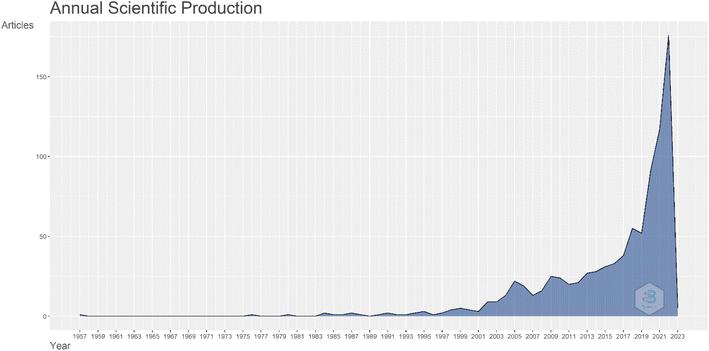 | ||
| Fig. 2 Graph the number of articles per year about water harvesting from air. Data is extracted from articles published in the Scopus database. | ||
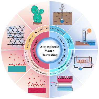
The starting point for extensive research on the production of water from humidity is the paper by Wahlgren et al.34 In 2001, he published a review of past scattered articles on methods of air humidity absorption. In his article, Walgren likened the production of atmospheric water to the construction of internal combustion engines in the late 19th century and stated that as the evolution of the gasoline engine made it possible to travel further, provided population dispersion and better living conditions, the evolution of AWH can also enable people to live comfortably in arid and dehydrated areas and reduce the water shortage crisis facing million. In the same year, Parker et al.35 inspired by nature to produce atmospheric water, studied water uptake by desert beetles and showed that to collect water from fog, it used the technology of combining hydrophilic and hydrophobic points. This type of beetle, to survive, it collects drinking water from the morning fog on its back. First, the fog drops are placed on the hydrophilic spots, then, by accumulating and forming large droplets, water reaches the hydrophobic area and heads down and moves to the head of the desert beetle. In 2017, Kim et al.36 revolutionized AWH technology. They designed a device that could produce water from the air using solar heat using MOFs at a relative humidity of 20% and a temperature of 60%. They used zirconium-based MOF-801 and was able to produce 0.2 liters of water per kilogram of MOF per day. The beginnings of research on MOFs as dehumidifiers go back to a study by Canivet et al.,37 who published a review article in 2014 and fully explained the stability of the muffs against moisture and suggested the use of zirconium-based MOFs to absorb water due to its stability in moisture and high porosity. To date, various methods for atmospheric water harvesting have been proposed, which can be divided into two main methods of condensation and sorption categories. In this review, atmospheric water harvesting methods are reviewed as shown in Fig. 3.
2.1 Parameters affecting
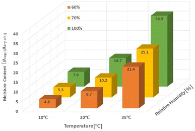
The amount of water in the air is determined by three main parameters including relative humidity, air temperature and total atmospheric pressure. Given that the atmospheric pressure is equal to 101.325 kPa, the relationships between these three parameters are presented in Fig. 4. The amount of water vapor per unit volume of air is called absolute humidity and the ratio of absolute humidity at a certain temperature to saturated humidity at the same temperature is called relative humidity (RH). It is important to emphasize that the process of producing water from air humidity requires less energy when the humidity is high. The most suitable atmospheric conditions for extracting water from the air are hot and humid (Fig. 4).38For generations, we need electricity to power the cooling source for vapor compression cycle (VCC) or thermoelectric cooling (TEC). The temperature of the cooling source must be lower than the dew point temperature of the system air to condense the water vapor. The performance of the system is evaluated by two indicators, the water harvesting rate (WHR) and the unit power consumption (UPC), which are defined as follows.
 | (1) |
 | (2) |
In the above relationships, WHR is mass of water produced per hour in kg h−1 and UPC is power consumption per unit mass of water produced in kW h kg−1. Higher WHR and lower UPC are desirable, because it means that more water can be obtained at a certain time and to produce the same amount of water requires less electricity consumption.39 The performance of water production systems is evaluated under various operational and design parameters such as sunlight, air temperature, relative humidity and air mass flow rate. The effect of these parameters on system performance and water harvesting rate (WHR) and the unit power consumption (UPC) is significant. The highest water production, as expected, is in hot and humid climates where sunlight, ambient temperature and relative humidity are high.
2.2 Potential of the world
The potential of different parts of the world to atmospheric water harvesting varies and depends on the dew point of that area. Because to atmospheric water harvesting, we have to lower the air temperature below the dew point, and this causes the humidity to condense and produce water. The lower the dew point, the less energy is needed to reach below the dew point and eventually condense the humidity. As shown in Fig. 5, the dew point varies in different parts of the world as well as in different months of the year. However, a temperature range can be specified for the dew point in each region and estimated the amount of energy required to atmospheric water harvesting.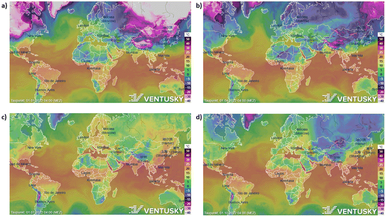 | ||
| Fig. 5 The potential of different parts of the world in four seasons to atmospheric water harvesting. (a) Dew point in different parts of the world in January 2022. (b) April (c) July (d) October. | ||
Atmospheric water harvesting with air mass flow rate (MFR) shows non-uniform behavior.40 The variations in water produced as a function of air mass flow rate are presented in Fig. 6 for different amounts of solar radiation. At low air velocities, air can cool in the vicinity of the cooler to lower temperatures, which increases the difference between the inlet and outlet humidity ratios. On the other hand, at high mass air flow rates, the evaporator must deal with more air mass and the difference between the humidity of the outlet air and the inlet air will be less. At some point in between, there is an optimal air mass flow rate that produces the maximum amount of water. The results show that with increasing solar radiation, the system can collide with more air mass, resulting in more water being produced.40
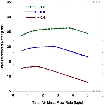 | ||
| Fig. 6 Total harvested water volume flow rate (L h−1) as a function of total air mass flow rate (kg s−1) for different solar radiation intensity (kW m−2). Reproduced from ref. 40 with permission from International Journal of Energy Research. | ||
2.3 Condensation methods
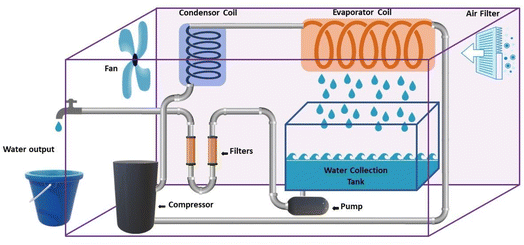
2.3.1.1 Condensation methods using vapor compression cycle generation. In some studies, VCC is used only for water production, while in other studies, VCC is used for air conditioning and water production. The latter is commonly used in central cooling systems and dense water is a by-product of the air cooling system.39 As shown in Fig. 7, generally, in the condensation methods, the air flow enters the spiral tubes inside a chamber with the coolant (evaporator). Inside this chamber, the air temperature decreases to the dew point, as a result of which water is produced. Then the dehumidified air enters the air flow tank after cooling and the produced water leaves as a by-product. This system consists of four main components including evaporator, expansion, condenser and compressor. The circulating liquid refrigerant receives heat from the air, lowers the temperature below the dew point, converts the steam into liquid, and in other parts, the heat returns to the environment.41
By examining this system, Yang et al.42 Showed that WHR is highly dependent on the relative humidity of the incoming air. They showed at 35 °C, when the relative humidity increases from 20% to 40%, WHR of 0.13 kg h−1 increases to 2 kg h−1. Zolfagharkhani et al.43 designed a small-scale sample of this device and studied it in one of the coastal cities of southern Iran, where the relative humidity is from 69% in May to 94% in December. This study showed that the WHR and UPC systems are highly dependent on ambient temperature and relative humidity and this system is more practical for hot and humid climates. In this study, the evaporation temperature is set at 60%. The results show that this system can produce 22–26 liters of water per day and has a WHR from 0.92 to 1.08 kg h−1 and UPC from 0.22 to 0.30 kW h kg−1. Magrini et al.44 have studied an air conditioning system. This system has provided proper ventilation and water generation for a hotel in Abu Dhabi. The amount of water harvested from each unit in summer 10.2 m3 per day announced, with WHR = 425 kg h−1. When the ambient humidity decreases in winter, this value to 2.5 m3 per day with WHR = 104 kg h−1 decreased. They found that the water generated by the VCC system was about 56.4% and meets the hotel's daily needs and reduces the total cost of water by 19%. One of the disadvantages of these devices is the use of chlorofluorocarbon (CFC) refrigerants, which damage the ozone layer. However, in recent years, new commercial gases or environmentally friendly refrigerants such as R134a have been used in these systems.45 Also, these devices should be for dew points less than 4.5 °C be designed, which require a lot of energy for the cooling cycle. The supply of this energy in new devices using wind turbines and solar panels has been considered. Rainmaker and Eolewater are two companies that use renewable energy to produce water from humid air.46 Eolewater company has used wind power to generate electricity and drinking water for remote areas. The VCC, which is installed to produce water, uses electricity generated by a wind turbine and under environmental conditions of 24% and 45% RH, produces 1500 liters of water per day and does not emit greenhouse gases. This system is designed to work automatically and it has very low maintenance costs. The Rhine Maker system uses wind energy only to supply power to the heat pump. Low operating and maintenance costs, flexibility in different capacities, no use of chemicals for water treatment are the features of this system.47 Research to develop wind technology to harvesting water from air must be carefully developed based on the design of the air turbine system. Because optimization of aerodynamic conditions, design, compliance with standards, material selection and other parameters are important in proper turbine operation. The use of wind turbines in areas with high humidity and coastal areas should be studied more carefully. Because the water vapor flow and the density of a thin layer on the surface of the blades reduce the performance of the system. On the other hand, foggy weather and frost caused by water vapor condensation also lead to reduced efficiency.48 In Table 1 we can see a summary of what was said about VCC Condensation systems.
| System | Temperature °C | Relative humidity % | Water harvesting rate (kg h−1) | Unit power consumption (kW h kg−1) | Reference |
|---|---|---|---|---|---|
| VCC1 | 35 °C | 20–40% | 0.13–2 | 0.18–2.08 | 42 |
| VCC2, southern Iran | 60 °C | 69–94% | 0.92–1.08 | 0.22–0.3 | 43 |
| VCC, hotel in Abu Dhabi | 35 °C | 60% | 425: Summer, 104: Winter | 8.47 | 44 |
| VCC3, compressor power: 1035 W | 19.4 °C, 26.7 °C | — | 1.5 | 0.69 | 49 |
| VCC4, two evaporator | — | 70–90% | 1.5–4.2 | 0.64 | 50 |
| VCC | 40 °C | 250 | 4.2 | 51 | |
| VCC, wind power Eolewater | 25 °C | 45% | 62 | — | 46 |
| VCC, wind power Rainmaker | 15 °C | 30% | 312.5 | — | 47 |
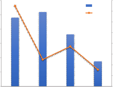
For a better review, the 4 VCC Condensation systems are compared with each other in terms of Water harvesting rate and Unit power consumption in Fig. 8. The VCC1 system generated less water than the VCC3 and VCC4 and the reason may be related to the low relative humidity in this system, in this experiment, it was found that the produced water is greatly affected by the relative humidity of the incoming air and when the relative humidity increases from 20 to 40%, the amount of water produced from 0.13 to 2.00 kg h−1 increases. The reason for higher energy consumption in this system than other systems can also be related to the low relative humidity in this study. As shown in Table 1, a wide range of power consumption in this case is shown, which indicates a significant reduction in power consumption with increasing relative humidity. As shown in Fig. 8, VCC2 and VCC4 have been tested in approximately the maximum relative humidity range. However, VCC4 generated more water than other systems, which could be due to the use of two parallel operators in the system, which ultimately generated more water. However, the impact of other parameters such as inlet air velocity and compressor power can not be ignored.
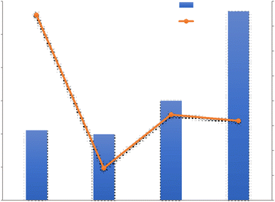 | ||
| Fig. 8 Unit power consumption (UPC) and water harvesting rate (WHR) diagram of VCC condensation systems. | ||
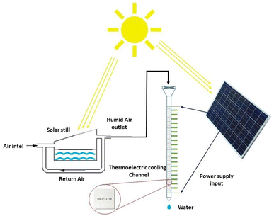
2.3.1.2 Condensation methods using thermoelectric cooling generation. Thermoelectric coolers are devices that work with direct current and consist of two different semiconductors. TEC cooling elements work based on the Peltier effect. The Peltier effect states that when an electric current passes through a circuit with two heterogeneous conductors, heat energy is taken from one connection and absorbed in the other connection, the first gets colder and the second gets warmer. Therefore, according to the Peltier effect, with the passage of electric current through them, a temperature difference is created and leads to the cooling effect.52 The volume of semiconductor chips is small and can effectively reduce the size of water generators and make them more portable than VCC systems. Therefore, TECs for designing simple systems and portable are suitable.53 Fig. 9 shows a schematic of TEC-based distillation system. Table 2 lists the condensation methods using TEC for harvesting water from air. Joshi et al.54 used this method to build a device for water harvesting from air. They installed 10 thermoelectric coolers in a 70 cm channel and tested it in several different weather conditions. According to this plan, the maximum water generation was 240 ml of water in 10 hours with a relative humidity of 90%. Also Tajeddini et al.55 used 18 thermoelectric coolers. Using this device at a relative humidity of 75%, water production equivalent to 26 ml per hour was reported. Jradi et al.56 generated water from air using a solar distiller. This study was performed in humid climate conditions of Beirut with temperature of 25 to 34% and relative humidity of 70% to 90%. First, in a solar distiller, the moisture content increased and then by a refrigerant channel containing 20 TEC coolers, water vapor condensed. Solar energy was used to supply the heat needed to evaporate, to heat the air during the process and to generate electricity to power the TEC modules. This system was able to produce at least 10 liters of water in a period of 10 hours. Data analysis showed that the maximum amount of fresh water produced was obtained between 3 and 6 pm and the amount of fresh water produced over a period of 5 months was examined. In August, water production 14.09 l day−1 and in October 10.06 l day−1. Which has WHR, respectively, 1.41 and 1.01 kg h−1. UPC proposed system of 0.58 in June to 0.39 kW h kg−1 in August which is less than the values reported in Tajeddini Study et al. The reason for this difference is the presence of a distiller that increases the inlet moisture.
| System | Temperature °C | Relative humidity % | Water harvesting rate (kg h−1) | Unit power consumption (kW h kg−1) | Reference |
|---|---|---|---|---|---|
| TEC1 | 30 °C | 90% | 0.024 | 7.5 | 54 |
| TEC2 | 35 °C | 75% | 0.026 | 2.5 | 57 |
| TEC, solar distillation | 25–34 °C | 70–90% | 1.01–1.41 | 0.39–0.58 | 56 |
| TEC3 | 24 °C | 67–92% | 0.0112–0.0251 | 2.23–5.21 | 58 |
| TEC4 | 26.5 °C | 70% | 0.00875 | 1.56 | 59 |
In Fig. 10, the four TEC systems are compared. TEC4 has the lowest electricity consumption with the lowest water production, which can be due to lower relative humidity and consequently lower water production. Since the amount of water produced is not significant, as a result, not much electricity has been consumed. TEC1 was tested using a cooling channel containing 10 TEC modules and was able to produce significant water. In this system, an internal heatsink was placed at the cold end to increase the heat transfer speed, which had a great effect on increasing the water produced. In TEC2, similar to the previous system, 18 parallel TECs were used and by increasing the number of modules, it was able to produce the highest amount of water compared to other systems at lower relative humidity. In general, it can be said that with the increase in the number of TEC modules, water production and electricity consumption can both increase and it is highly dependent on the relative humidity and the flux of the incoming air flow that it is very important to find an optimal value.
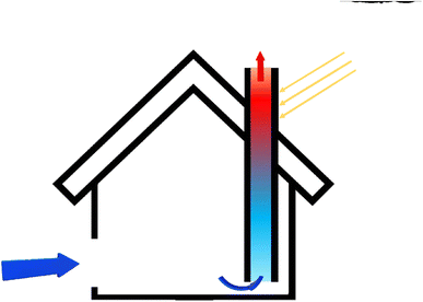
By placing the turbine in the direction of the rising hot air flow, electricity can be generated. This system is called solar chimney power plant (SCPP). In a solar chimney power plant, instead of a wall, a solar collector is used to absorb energy, which includes a transparent roof, under which the air is heated by the sun's radiant energy. This technology is suitable for hot and dry areas or deserts with high average sunlight.61 Ming et al. stated that SCPP is not only a solar system for accessing electricity, but also a device that can extract water from air. Instead of a collector, they used black pipes around the chimney. After the sun shines and the humid air inside the collector heats up, due to the density difference between inside and outside the chimney, the humid air flows upwards due to the convective flow. Because the chimney is high enough, the humid air inside the chimney rises so high that the temperature drops below the dew point, and the humid air vapor begins to condense on any solid surface. This is the process by which clouds are formed.62 This system has been used in 9 different cities with ambient temperature, relative humidity, solar radiation and different rainfall conditions. The results show that the plant can produce 29.7 × 10⁶ tons of water per year in the coastal city of Chengdu, which has a relative humidity above 75%, and 37.9 × 10⁶ tons per year in Guangzhou, with a relative humidity above 80%.63 The large WHR in this method depends on several factors such as the velocity of the chimney inlet air and the height of the chimney.62 The process of that SCPP with water vapor condensation on the sea surface was depicted in Fig. 12.
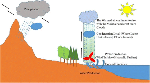 | ||
| Fig. 12 The process of a SCPP with water vapor condensation on the sea surface. Reproduced from ref. 62 with permission from Energy Conversion and Management. | ||
3 Atmospheric water harvesting using sorption methods
As mentioned, due to the low energy consumption of sorption methods, their use of clean energy and their lack of electricity connection, these systems have received a lot of attention. Since most of the areas that suffer from water shortage crisis are dry areas with low relative humidity and in such cases, it is not possible to use other systems. Therefore, these systems are of special importance and the following is a review of atmospheric water harvesting using sorption methods.3.1 Sorption methods using bioinspired
There are many plants and animals in nature that absorb water from the air to survive. The beetles of Namib Desert and some spiders are examples of these natural substances. Spider silks are one of the most useful materials that nature has given us. There are many types of spiders, they can be easily seen in many parts of the world. Dew droplets can be easily seen on the spider silk every morning, indicating the spider silk's ability to absorb water from the air. The basis of water collection in spider silks is the pressure difference between inside and outside the curved surface, which is called Laplace pressure.67 The relationship between pressure and surface tension is established by the Young–Laplace equation. If a drop of liquid is placed on a smooth solid surface, the surface wettability can be described using the Young–Laplace equation:68
 | (3) |
As shown in Fig. 15, θ is the contact angle of the droplet on a smooth surface, γSA is the surface tension between solid and air, and γSL is the surface tension between solid and liquid. This equation was first proposed by Young in 1805, but only applied to surfaces that were physically smooth or chemically similar. Because of roughness and heterogeneity, Wenzel proposed a new relationship. Wenzel calculated that θ changes to θ when the liquid is in contact with a microstructure surface. As shown in the Wenzel model (Fig. 15B), the liquid is in contact with the solid surface and is completely locked on uneven surfaces. Wenzel first proposed a new model for rough surfaces in 1936, stating that a rough material has a higher surface area than a smooth surface, and stated the contact angle as follows:69
cos![[thin space (1/6-em)]](https://www.rsc.org/images/entities/char_2009.gif) θ* = r θ* = r![[thin space (1/6-em)]](https://www.rsc.org/images/entities/char_2009.gif) cos cos![[thin space (1/6-em)]](https://www.rsc.org/images/entities/char_2009.gif) θ θ
| (4) |
 | ||
| Fig. 15 Wetting behavior of solid substrates (A) Young's model (B) Wenzel's model (C) Cassie's model. Reproduced from ref. 67 with permission from Chemical Society Reviews. | ||
In Cassie's model, it is assumed that the droplet is only in contact with uneven surfaces on the solid substrate, the liquid cannot pin into valleys on the uneven surface, and air cavities are trapped beneath the liquid. The Cassie model equation can be defined as follows:70
cos![[thin space (1/6-em)]](https://www.rsc.org/images/entities/char_2009.gif) θ* = fSL θ* = fSL![[thin space (1/6-em)]](https://www.rsc.org/images/entities/char_2009.gif) cos cos![[thin space (1/6-em)]](https://www.rsc.org/images/entities/char_2009.gif) θ1 + fLA θ1 + fLA![[thin space (1/6-em)]](https://www.rsc.org/images/entities/char_2009.gif) cos cos![[thin space (1/6-em)]](https://www.rsc.org/images/entities/char_2009.gif) θ2 θ2
| (5) |
These are three important models used to describe the wetting behavior on the surface: the Young equation is used for the ideal flat surface and the other two equations are used to describe the effect of roughness on the apparent contact angle of a liquid drop on a rough solid surface.
The spider silk, which is moisturized, have alternating knot-like roughness's with joint between them that are parallel structures (Fig. 16). This structure causes a flow of water by creating a driving force due to the presence of surface energy gradients. Water condenses on both areas of the nodes and joints, but the topography of the joints causes water to move toward the water-collecting sites at the knots.71 Joints compared to spindle-knots, have a greater contact angle than water droplets and spindle-knots compared to joints are more hydrophilic and have higher surface energy. The surface energy gradient can be due to differences in the surface chemical composition or surface roughness, and such a gradient drives water droplets to a higher energy surface. In the case of spider silks, the chemical composition of the surface along the fiber does not change much, but the joints in the fiber direction have less roughness, so the water contact angle in the joint area is greater than spindle-knot. Due to the difference in surface energy, water droplets move from hydrophilic joints with less surface energy to more hydrophilic spindle-knot with more surface energy.72
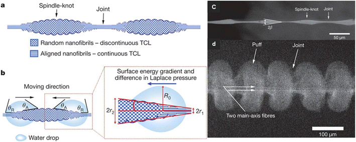 | ||
| Fig. 16 Mechanism of directional water collection on wet-rebuilt spider silk. (a) schematic of spindle-knots of spider silk, which are interweaved by highly random nanofibrils (b) surface energy gradient and Laplace pressure (c) SEM image of structure of wet-rebuilt spider silk (d) SEM images of structures of dry capture silk of cribellate spider. Reproduced from ref. 72 with permission from Nature. | ||
Also, Namib Desert beetles survive by absorbing moisture from the air. As shown in Fig. 17, the protrusions on the back of the Namib Desert beetle can adsorb air moisture. There are two different parts at the top of the ridges, including the hydrophobic and hydrophilic zone. The hydrophobic zone can direct the droplets to the hydrophilic zone and cause more absorption and accumulation of water droplets in the hydrophilic zone.73
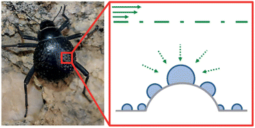 | ||
| Fig. 17 Schematic of Namib Desert beetle's water absorption. Reproduced from ref. 73 with permission from Nature. | ||
The dew bottle with its steel body is made inspired by the water absorption method in the structure of Namib beetle (Fig. 18). Horizontal and vertical grooves on the surface of the bottle allow steam to condense faster on the surface of the bottle and the formation of dew on the surface is quickly transferred to the interior of the container, which is suitable for desert nomads. The design won the Bronze Award at the 2010 Design Awards.74
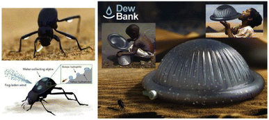 | ||
| Fig. 18 Dew bottle, inspired by the method of water absorption in the structure of the Namib beetle. Reproduced from ref. 75 with permission from Renewable and Sustainable Energy Reviews. | ||
Moazzam et al. Also presented a polypopamine-coated nanostructure based on the structure of the Namib beetle, which collected water in 97 mg cm−2 h−1 was reported.76
3.2 Sorption methods using fog collector
Fog is made up of tiny droplets that result from the saturation of air with water vapor. Fog can be trapped by mesh net and then water droplets formed.77 Mesh netting should have both hydrophilic and hydrophobic properties. Hydrophilicity is used to absorb more water droplets as well as hydrophobicity to collect water towards the collection tank. The fog droplets sit on mesh net and then move downwards and are moved by the gravity forces of the tank.78 Harvesting water from fog in different parts of the world is one way to deal with water shortage problems. This method does not require energy to produce water and by applying the appropriate structure to the water collection surfaces, the process efficiency increases. Standard fog collectors (SFCs) and large fog collectors (LFCs) are the two main groups of mesh. SFC is mainly used in studies to evaluate the amount of mist water that can be collected in specific locations and has a surface area of 1 × 1 m2. The LFC is much larger and is a mesh with 4 m high and 10 m wide to increase water harvesting.79 In Morocco, a center of 600 m2, there is a large collection of lattice sticks to trap thick fog and convert it into drinking water, which in the last 6 years has produced 17 gallons of safe drinking water per square meter.75 Fig. 19 shows Moroccan fog harvest project and Warka Water Tower or Bamboo Tower in that work. The Warka tower, which is made of bamboo and polyester mesh, is also designed to produce water from fog. This tower is 10 m high and 4 m wide and produces 50 to 100 liters of water daily.80 The Moroccan organization has acknowledged that water production can have a positive social impact in addition to economic ones. Previously, women had to walk long distances to provide water for their families. Young girls had a similar pattern, and most of them did not have time to go to school, resulting in a gender imbalance. Rural water supply has not only reduced the pressure on existing groundwater resources, but also on the female gender, and has enabled the emergence of a different social balance and the creation of new opportunities.81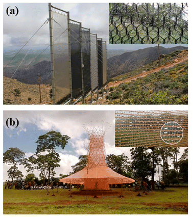 | ||
| Fig. 19 (a) Moroccan fog harvest project; (b) warka water tower or bamboo tower. Reproduced from ref. 75 with permission from Renewable and Sustainable Energy Reviews. | ||
3.3 Sorption methods using desiccants
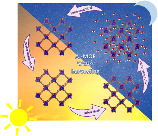
The main component in sorption methods is a desiccants that can spontaneously absorb moisture in the air. Depending on the chemical structure of the material used in these systems, climatic conditions and the efficiency of the devices can vary. Some substances are capable of producing water at low RH, others at saturated RH, some through physical adsorption, and some through physical and chemical adsorption. For the desorption stage and water production, the release process begins with the generation of heat and then the water produced can be collected. Examining the structure of the desiccants can help us find the right adsorbent. Finding desiccants with a porous structure that can provide us with a higher surface area to absorb more water can be the first step in choosing an adsorbent. Also, suitable hydrophilicity, fast vapor diffusion and molecular diffusion are among the superior adsorbent properties.82 Fig. 20 shows some of these more important desiccants along with important features for selecting a suitable adsorbent.As mentioned, the choice of adsorbent type in adsorption systems is very important to improve the performance of the whole process. The amount of water vapor mass that the adsorbent can absorb indicates the adsorption capacity of each system and the amount of energy consumed during the desorption process is significant. Therefore, to select a suitable adsorbent, factors such as: high water absorption, low energy consumption for the water release stage, rapid water absorption and desorption, and stability in the adsorption and desorption cycle are effective. Adsorption can be considered as a phenomenon in which gas or liquid molecules are adsorbed to liquid or solid materials and change the structure and volume of the adsorbent material. Water molecules can be adsorbed by physical or physical and chemical reactions with adsorbents. Chemical adsorption depends on the stoichiometry of the reaction and the concentration of the reactants, while physical adsorption is usually by osmotic effect.82,83 Desiccants can absorb moisture at low temperatures and have the ability to desorb some or all of that moisture at high temperatures, and that's a key part of AWH using desiccants. As shown in Fig. 21, absorption systems at night absorb moisture from the air and release water at high temperatures during the day when the sun is shining. Therefore, the adsorption and desorption process in these systems can be likened to a cycle that the most important issue in the process of this cycle is the stability of the adsorbent that after successive cycles of water adsorption and desorption can maintain its original ability and capacity to absorb water. The first part of this cycle, which includes water absorption, is done at night, and the second part, which includes water absorption and production, is done during the day. At night, when the air is cooler and the humidity is at its maximum, the water vapor in the air is absorbed by the hydrophilic sites of the desiccant. Here, hydrophilicity is an essential element for desiccant, especially in situations where the relative humidity of the air is low. But this hydrophilicity should not be so high that during desorption, a lot of energy is needed to break the strong bonds. Water absorption continues until the desiccant's porosities are filled. Since the evaporation process is an endothermic process, this energy can be provided by sunlight. During the day, as the temperature of the desiccant's surface increases, the water in the porosities evaporates and then the excreted water can be harvested, thus continuing the adsorption and desorption cycle.
These systems have the feature of periodic operation, which reduces the daily water production capacity compared to condensation technologies. The performance of adsorption technology is usually measured by DWHR (daily water harvesting rate (kg day−1)).39 Classic desiccants can be divided into two categories in terms of absorption mechanism. Some of them can adsorb water through physical adsorption and others through physical and chemical absorption (Fig. 22). Zeolite, silica gel and activated alumina are classical desiccants that often have physical adsorption, but hygroscopic salts such as LiCl, MgCl2 and CaCl2 have physical and chemical absorption.84 Adsorption thermodynamics is related to the intrinsic properties of materials. Physical adsorption is usually driven by the osmotic effect and van der Waals forces. Chemical adsorption depends on the stoichiometry of the reaction and the concentration of the reactants, and the adsorbent surface has active sites for absorption of molecules through strong chemical bonds, such as hydrogen bonding, coordination effect, and electrostatic interactions.82
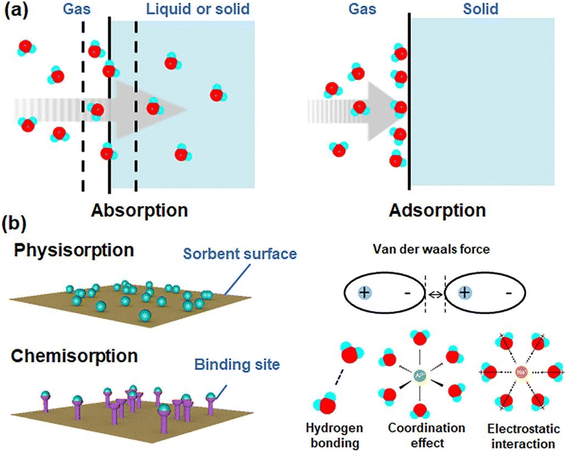 | ||
| Fig. 22 Moisture sorption mechanisms. Reproduced from ref. 82 with permission from ACS Materials Letters. | ||
3.3.1.1 Zeolite. In 1925, Chabazite, a natural zeolite, was studied for separation applications, and zeolites were introduced as “molecular sieve”.86 Generally, molecular sieve is a porous material that has the same porosity size, and this property makes them ideal for separation and adsorption. When a gas or liquid passes through a molecular sieve, particles larger than the size of the pores cannot pass through or be absorbed.87 Zeolites are molecular structures that have a very good ability to absorb water vapor due to their unique surface properties and the presence of various elements such as aluminum, silicon, phosphorus, and sodium in their structure. Due to the presence of crystalline aluminosilicates in their structure, they absorb water vapor even at lower relative humidity. However, due to the strong bond with water molecules, the regeneration of water molecules after adsorption is difficult. The water vapor adsorption capacity of zeolites mainly depends on the
 ratio in their structure. Zeolites with lower
  ratios usually have higher water vapor adsorption capacity due to the high concentration of active hydrophilic sites (Fig. 23).88 Aluminum is the adsorption site, which has the effect of coordinating with water molecules, and its amount affects the ability to adsorb water. The porous structure of zeolite also determines the water uptake capacity, the larger pore volume usually leads to high adsorption capacity. Their essence is that water molecules enter the molecular sieve and water is polarized by positive charges in the pores and is adsorbed due to the Van der waals force. This process continues until the pores are filled with water molecules. However, high affinity for water makes it difficult to release adsorbed water and requires high energy consumption, so high regeneration temperatures are required to release and condense water, making them unsuitable for efficient AWH.82
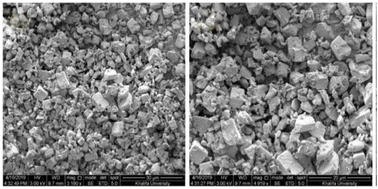 | ||
| Fig. 23 SEM image zeolite AQSOA-Z02. Reproduced from ref. 88 with permission from Microporous and Mesoporous Materials. | ||
3.3.1.2 Silica gel. Silica gels are nanoscale porous polymers with a large amount of hydroxyl groups on the surface. Hydroxyl groups combine with water molecules in the air, so they can absorb water molecules. For example, the substrate of a hydrogel is sodium alginic acid, the structure of which contains polymers with hydrophilic crosslinks. A three-dimensional lattice structure connected on both sides by covalent bonding, hydrogen bonding or van der Waals forces ensures that the hydrogel retains its original shape when absorbing water. However, these strong bonds cause problems for water desorption in hydrogels, so this material needs a high reduction temperature for desorption.89 The adsorption rate on silica gels increases with the number of hydroxyl groups present on the surface as the adsorption sites on the surface increase. Silica gels have nano-sized pores and have a high specific surface area that can be useful in absorbing moisture90 but not able to absorb water at low relative humidity and can be said to be unsuitable for producing water in dry air.82 Fig. 24 shows an SEM image of silica gel.
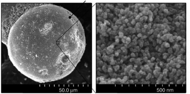 | ||
| Fig. 24 SEM image silica gel. Reproduced from ref. 91 with permission from Thin Solid Films. | ||
3.3.2.1 Hygroscopic salt. Another type of classical desiccants that absorb water both physically and chemically is hygroscopic salts. For example, CaCl2 can absorb 97% of its weight by forming a bond.92 William et al.31 studied a type of water generator called the solar rig operation system and used CaCl2 solution as an desiccant. They were able to harvest daily 910 gr m−2 water from air at relative humidity 70% (Fig. 25).
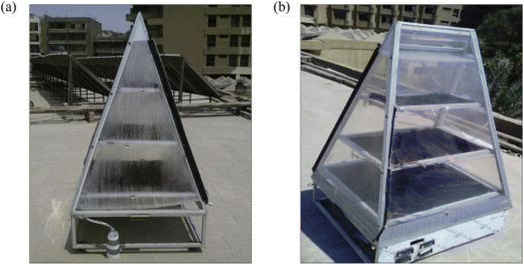 | ||
| Fig. 25 Solar rig operation system (a) during the day. (b) At the end of the day. Reproduced from ref. 31 with permission from Energy. | ||
Hygroscopic salts absorb moisture through the hydration reaction, but the possibility of agglomeration as well as the formation of inactive layers on the surface of the particles by the hydration reaction is high, which can reduce moisture permeability and ultimately reduce the amount of water absorbed. Another problem is the tendency of these materials to liquefy by absorbing moisture, which can cause corrosion of the unit.93 The main challenge for hygroscopic materials is the high energy consumption in the desorption stage. Due to the fact that the whole adsorbent solution is also heated.82 To solve this problem, hygroscopic salts can be combined into the pores of another adsorbent such as silica gel or activated carbon, so we will continue our discussion on composite adsorbents.
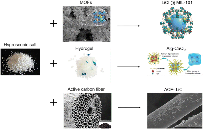 | ||
| Fig. 26 Composite desiccants. Reproduced from ref. 83 with permission from Solar Energy Materials and Solar Cells. | ||
Table 3 summarizes what was reviewed. It is observed that most of these adsorbents are applicable at high relative humidity. While the supply problem mostly affects areas with hot and dry loads of low relative humidity. Next generation adsorbents, in addition to good hydrophilicity and stability in the aquatic environment, must be able to absorb water at low relative humidity. And be able to produce water in the desorption stage at low temperatures. Metal–Organic Frameworks (MOFs) are hoped to meet all of the above requirements. Due to the changes that can be made at the level of MOFs as well as the extremely high porosity, these materials are suitable for overcoming the mentioned challenges. An important step is the release of water from the MOF, which can be done with solar energy because sunlight is often abundant in arid areas with low RH.100
| Composite | Temperature °C | Relative humidity | Water harvesting rate (gr grComposite−1) | Unit power | Reference |
|---|---|---|---|---|---|
| CaCl2 | 26 °C | 70% | 910 gr m−2 | Solar | 31 |
| Licl@MOF | 30 °C | 30% | 0.3 | Solar | 85 |
| Silica-based CuCl2 | 17 °C | 20% | 0.25 | Solar | 94 |
| HCS-LiCl | 25 °C | 60% | 1.25 | Solar | 95 |
| Zeolite 13-CaCl2-MWCNT | 30 °C | 35% | 0.5 | Solar | 97 |
| Zeolite 13 | 30 °C | 0.09 | Solar | 97 | |
| PPSD | 40% | 0.43 | Solar | 98 | |
| SD | 40% | 0.05 | Solar | 98 |
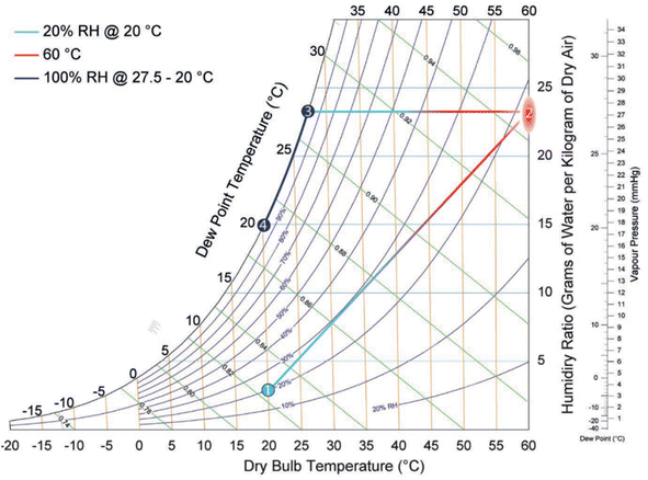 | ||
| Fig. 27 Psychometric graph. Reproduced from ref. 100 with permission from Advanced Materials. | ||
MOFs can absorb air with low relative humidity due to their porous structure and raise it in a system depending on the relative humidity, then it can be compressed and produced water by direct cooling method such as thermoelectric cooling.101 It is even possible to optimize heat transfer by using a substrate such as porous copper foam and adding graphite to it, which accelerates desorption and shortens the cycle time. However, compared to other materials, MOF materials are more expensive which is not economical.83 Metal–Organic Frameworks (MOFs) are porous structures with metal clusters and organic ligands. The presence of an organic component in MOFs makes them more active than zeolites. In MOFs, new structures can be achieved by changing organic linkers and metal clusters. So far, more than 20![[thin space (1/6-em)]](https://www.rsc.org/images/entities/char_2009.gif) 000 MOFs have been synthesized. However, the applications of most MOFs face obstacles due to their instability and scientists are always trying to stabilize MOFs.102 Proper selection of organic linkers can create a specific topology for each MOFs. For example, in Fig. 28, by selecting terephthalic acid as a ligand whose structure is linear and according to the geometry of each metal cluster, a MOF with a specific topology can be obtained. Each topology has a specific pore size and specific surface area.103
000 MOFs have been synthesized. However, the applications of most MOFs face obstacles due to their instability and scientists are always trying to stabilize MOFs.102 Proper selection of organic linkers can create a specific topology for each MOFs. For example, in Fig. 28, by selecting terephthalic acid as a ligand whose structure is linear and according to the geometry of each metal cluster, a MOF with a specific topology can be obtained. Each topology has a specific pore size and specific surface area.103
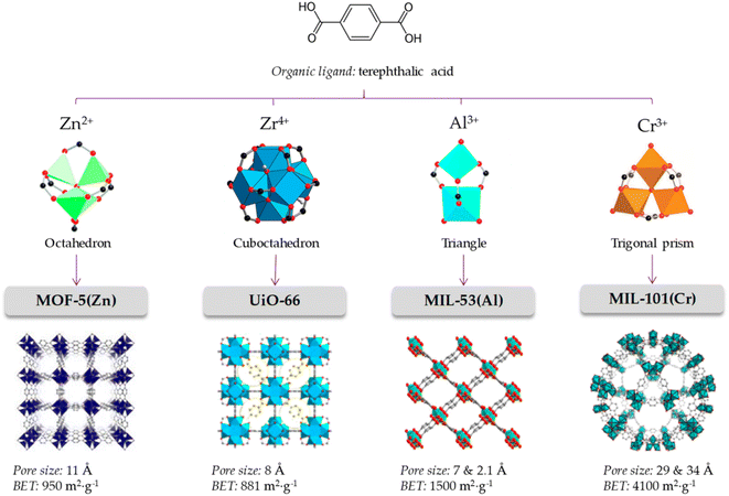 | ||
| Fig. 28 Schematic types of clusters in the construction of MOFs with terephthalic acid linkers. Reproduced from ref. 103 with permission from MDPI. | ||
Factors such as chemical, optical, mechanical and thermal stability can affect the behavior of MOFs and according to the needs and performance of MOFs in the desired environment, appropriate MOFs can be selected.102 For example, to take advantage of the properties of MOFs in aqueous media, it is important not to hydrolyze MOFs in the presence of water. Also, depending on the pH of the work environment, different types of MOFs can be used. For example, azolate MOFs with low-capacity metal clusters have strong stability in alkaline environments but are degraded by acid. Fe-MIL-88 or Cr-MIL-88 MOFs show low mechanical stability but high chemical stability. Therefore, the correct choice of MOFs based on operating environments should be considered.104 Compared to classical adsorbents such as zeolite, silica gel, or hygroscopic salts, MOFs can absorb more water in ambient air with a relative humidity of 20% and require a lower reduction temperature to release. Therefore, natural heat sources such as sunlight can be used to generate heat.105 The performance of MOFs in humid environments can be a determining factor in the ability to use these materials as adsorbents, and understanding the parameters that contribute to this sensitivity is very important to raise MOFs to the application level. Given the high quantity and diversity of MOF structures, it is reasonable to expect that while some of these materials are unstable in the presence of water vapor, there are also a significant number of stable MOFs.106 Terzis et al.107 investigated the behavior of fluidization of MOF-801 for absorbing water vapor. They proposed that the fluid state can create a higher boundary (interface) between the adsorbent and the air. In this research, 40 absorption and desorption cycles of 26 minutes were performed at a temperature of 22 °C and RH = 18%, which produced 0.33 l h−1 kg MOF of water, and also 55 cycles of 36 minutes at a temperature of 23.5 °C and RH = 39%, which produced 0.52 l h−1 kg MOF water was collected. MOF-Co2Cl2BTDD was studied by Rieth et al.108 Investigations showed that this MOF can absorb 82 wt% of water under 30% relative humidity. One of the important characteristics of this material is the higher diameter of pores compared to other materials. Yilmaz et al.109 introduced a polymer-metal–organic framework using MIL-101(Cr) to produce water from the atmosphere. They produced 6 grams of fresh water per gram of adsorbent per day at 90% relative humidity. Mulchandani et al.33 predicted the atmospheric water harvesting potential by MIL-101(Cr), silica gel and zeolite. Using Monte Carlo simulations and US geographic mapping, they suggested that MOF produced a maximum amount of water of 1.3 l m−2 day−1. Silva et al.110 studied the behavior of water vapor absorption by MIL-125(Ti)_NH2. The results showed that by using MIL-125(Ti)_NH2, gwater gMOF−1 0.32 water can be produced daily from air at a temperature of 10 to 100. Trapani et al.111 investigated the moisture absorption behavior of different MOFs and finally introduced UiO-66 as the best candidate for producing water from air. The water absorption tests were performed at 25 °C and 40% relative humidity and the desorption process at 45 °C with 10% RH and finally 0.054 g of water was collected per gram of MOFs. Logan et al.1 also investigated 9 stable MOFs with various structures. The results showed that Zr-MOF-808 can produce up to 8.66 L H2O kg−1 MOF day−1. MIL-160(Al) MOF was studied by Silva et al.112 The results of the daily production of 0.305 grams of water per gram of MOFs at a temperature of 80 °C and a flow rate of 0.5 m3 s−1 were reported. Song et al.113 reported a MOF-derived porous carbon as an adsorbent with fast adsorption kinetics for the production of water from air with high efficiency. Experiments showed that this adsorbent can produce 0.18 l kgcarbon−1 h−1 of water at 30% relative humidity under the light of sun. In Table 4, we see the MOFs that have been used to harvesting water from the atmosphere.
| MOF | Temperature °C | Relative Humidity % | Water harvesting rat | Unit power | Image | Reference |
|---|---|---|---|---|---|---|
| MOF-801 | 25 °C | 20% | 2.8, Lwater kgMOF−1 day−1 | 1 kW m−2 |  |
36 |
| MOF-801, MOF-303, MOF-801-graphite mixtures | 25 °C | 15% | 100 grwater kgMOF−1 day−1 | Solar | 114 | |
| MOF-801 | 15–20 °C | 30% | 0.25, Lwater kgMOF−1 day−1 | Solar | 115 | |
| MOF-303 | 27 °C | 10% | 0.7, Lwater kgMOF−1 day−1 | 116 | ||
| 27 °C | 32% | In desert 1.3, Lwater kgMOF−1 day−1 | ||||
| MOF-801 | 22 °C | 18% | 0.33, Lwater kgMOF−1![[thin space (1/6-em)]](https://www.rsc.org/images/entities/char_2009.gif) h−1 h−1 |
Solar | 107 | |
| MOF-Co2Cl2BTDD | 25 °C | 30% | 0.82 gH2O gMOF−1 | 400 kW h m−3 |  |
108 |
| Polymer-MOF, MIL-101(Cr) | 30 °C | 90% | 6 grwater kgP-MOF−1 | 1 kW m−2 | 109 | |
| MIL-101(Cr) | — | 40% | 3.1, Lwater m−2 day−1 | 33 | ||
| Mil-125(Ti)-NH2 | 11 °C | 20% | 0.32 gwater gMOF−1 day−1 | Solar | 110 | |
| UiO-66 MOFs | 25 °C | 40% | 0.054 gwater gMOF−1 | Solar | 111 | |
| Zr-MOF-808 | 22 °C | 70% | 8.66, LH2O kgMOF−1 day−1 | 1 | ||
| MIL-160(Al) MOF | 30 °C | — | 0.305 gwater gMOF−1 |  |
112 | |
| MOF-derived nanoporous carbon | — | 30% | 0.18, Lwater kgcarbon−1![[thin space (1/6-em)]](https://www.rsc.org/images/entities/char_2009.gif) h−1 h−1 |
Solar, 1 kW m−2 |  |
113 |
3.3.4.1 Introducing MOFs. Metal–organic frameworks consist of two main components, which are:
● A metal ion or cluster of metal ions (secondary structure units, SBU).
● An organic ligand called a linker.
MOFs are made up of metal ions that are strongly bonded together by molecules to form crystalline, completely porous structures. By modifying SBUs and connectors, a wide range of MOFs with different structures and applications can be synthesized, which allows for a high degree of chemical and structural adjustment, and allows their properties to be adapted for different purposes.117 As Fig. 29 shows, due to their unique properties, MOFs, such as controllable pore size, stable porosity, high chemical, and mechanical stability, increased active surface area, and easy operation, have been used as adsorbents, catalysts, supercapacitors, and drug delivery, especially for cancer treatment.118 The extremely high porosity of MOFs shown can be used to absorb gas and water vapor. However, the uptake of gases such as H2, CH4 and CO2 has been extensively studied but water absorption has received less attention. This may be because the first generation of MOFs showed low stability in the presence of water but today this problem has been solved and MOFs with stability in the presence of water have been reported.100
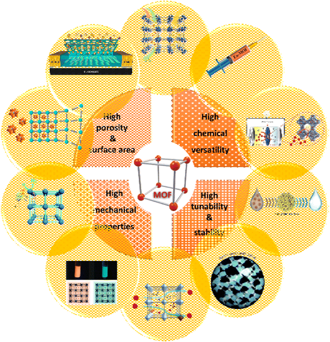 | ||
| Fig. 29 Different properties and applications of MOFs: gas storage and separation. Reproduced from ref. 119 with permission from Materials Today. Drug delivery. Reproduced from ref. 120 with permission from Battery and supercapacitor. Reproduced from ref. 121 with permission from Inorganic Chemistry. Water purification. Reproduced from ref. 122 with permission from ACS applied materials & interfaces. Resin. Reproduced from ref. 123 with permission from Inorganic Chemistry Frontiers. Proton conductivity. Reproduced from ref. 124 with permission from Advanced Materials. Luminescence marker. Reproduced from ref. 125 with permission from American Chemical Society. Photocatalyst. Reproduced from ref. 126 with permission from Chemical Communications. Heterogeneous catalysis. Reproduced from ref. 127 with permission from ACS catalysis. Chemical sensor. Reproduced from ref. 128 with permission from ACS applied materials & interfaces. | ||
3.3.4.2 MOFs synthesis. The synthesis of MOFs is mostly done in the liquid phase and by the solvothermal method. Therefore, energy supply and suitable solvent selection play an important role in the synthesis process. Various criteria such as reactivity, solubility, toxicity, and boiling point are checked to find the right solvent. Also, the solvent plays an important role in determining the thermodynamic parameters and activation energy of the reaction.129 The energy required to carry out the chemical reaction is generally supplied using conventional electrical heating. Also, the necessary energy can be provided by other methods such as electric potential, electromagnetic radiation, ultrasonic waves, or mechanical. By changing the energy source, other parameters such as time and pressure can also be changed, which has a great impact on the final product and its morphology. Therefore, by using different synthesis methods, it is possible to obtain new compounds with different particle sizes and size distributions, as well as different morphologies that can affect the properties of materials. For example, different particle sizes in porous materials can affect the diffusion of guest molecules, which has a direct effect on catalytic reactions or adsorption and separation of molecules. Also, in order to commercialize MOFs, a lot of research is being done to find a synthesis method with less cost, temperature and time. Reduction of synthesis time is an important factor that can lead to continuous syntheses that are useful for large-scale production. Also, by reducing reaction time and temperature, it leads to more energy efficient processes and less synthesis equipment.130 In the following, we will give a brief explanation of the synthesis methods and their advantages and disadvantages.
Solvothermal synthesis: Solvothermal (hydrothermal) reactions take place inside high pressure reservoirs, resulting from the boiling point of the solvent. Many reactants can undergo unexpected chemical changes under solvothermal conditions, which are often accompanied by the formation of nanoscale morphologies that cannot be achieved by conventional synthesis methods. In most cases, organic solvents with high boiling temperature have been used for solvothermal reactions, and the most used solvents are methanol and ethanol. The temperature range of solvothermal reactions is also different according to the temperature required to carry out the reactions. Usually, glass tubes are used for low temperature reactions, while Teflon autoclaves are needed for reactions at temperatures higher than 400 K.131
Microwave-assisted synthesis: Microwave synthesis is a fast method for the synthesis of MOFs. The necessary heat for solubilization during the process is provided by microwaves. The quality of the crystals synthesized through microwave is equal compared to the crystals produced by the solvothermal process, but the synthesis is much faster. By reducing the synthesis time, not only energy consumption is saved, but also production can be increased, which benefits industrial production processes.132 Some molecules that have dielectric moments, such as water, rotate to align themselves with the alternating electric field of microwaves. As a result of this movement, the molecules collide with each other and the required heat is created. Microwaves from a oscillator that converts high voltage direct current to high frequency radiation. It is formed and produces electromagnetic waves with wavelengths in the range of 1 m to 1 mm (300 MHz to 300 GHz). Microwave-assisted synthesis depends not only on the MOF in question but also on the device used. Also, since some parameters such as temperature, radiation power, reaction time, and pre-material composition ratio can be changed, research group preferences can be affected and because reactions are fast and the number of variable parameters is high, finding a system can be time consuming. The most important parameter of the tool in microwave heating is the power of radiation and how to create, deliver and control it during the reaction. This depends largely on the device used.133
Ultrasonic synthesis: Sonochemical is a phenomenon in which the radiation of ultrasonic waves (20 kHz–10 kHz) to the liquid and carrying out the process of porosity, which includes the formation, growth and collapse of bubbles in the liquid and the creation of hot places with high pressure and temperature in a short time, leads to changes are physical or chemical. Indeed, the formed bubbles act like micro-reactors in which the reaction takes place. The final conditions can lead to chemical reactions with the development of rapid formation of crystallite nuclei. Sonochemical methods are better than hydrothermal methods by producing homogeneous and uniform nucleation centers and reducing nucleation time. For example, the synthesis of MOF-5 by sonochemical method can produce 5–25 μm crystals in 30 minutes, which is similar to the synthesis by solvothermal or microwave method.134
Mechanochemical synthesis: Mechanochemical synthesis is a fast and easy method that is proposed as MOFs green synthesis. In this method, a chemical reaction occurs by using mechanical forces, so that MOF is synthesized by adding a small amount of solvent and by grinding the solid reactants.135,136 This method is significant due to its economic efficiency, high speed and compatibility with the environment, but low crystallinity and the possibility of forming an amorphous structure are among the disadvantages of solid phase syntheses.137 Another problem of mechanochemical synthesis is the formation of new secondary phases that arise as a result of competitive reactions.138
Electrochemical synthesis: Electrochemical synthesis is another method that is performed at a lower temperature and at a higher speed than the solvothermal method. In this method, MOFs are synthesized through anodic dissolution in an electrochemical cell. In electrochemical synthesis, there is no need for the presence of metal salt, but metal ions are supplied by using a metal sheet as an electrode and then oxidizing the electrode. It is easy to observe and control the synthesis conditions in this method, and the oxidation state of the metal can be carefully controlled by adjusting the voltage. One of the disadvantages of this method is that in order to dissolve the organic linker, organic solvents are often required, while little is known about the electrochemistry of such media.139 Moreover, few MOFs have been synthesized by this method so far, even though this method allows the synthesis of various MOFs, the limitation is that only MOFs with the same metal as the metal electrode can be synthesized (e.g. Al-MOF on an aluminum substrate).140
Slow diffusion: The slow diffusion method does not require external energy for the reaction and is performed at ambient temperature, which is why it requires much more time than other methods. In this method, after preparing a supersaturated solution containing metal ions and organic ligands, with the slow evaporation of the solvent at ambient temperature, a concentration gradient is created. Then, leaving the supersaturation state, nucleation begins and enables the formation of large MOFs crystals.141
One-pot: The one-pot synthesis is another simple method for the synthesis of MOFs because it is carried out at ambient pressure and temperature, and if needed, the temperature is increased using an electric heater, and for this reason, it consumes relatively little energy.142
3.3.4.3 MOFs as water sorption. According to the unique characteristics of MOFs, which was mentioned, one of the wide applications of these materials is in the absorption and separation of gases. Having several important features in some of these materials can make them superior to other existing absorbents for absorbing moisture in the air, which we will discuss below.
Mofs water stability: When the name of moisture comes up, the first thing that can be of concern is the stability of MOFs in the presence of water. Many MOFs do not have long-term stability when exposed to water, and the presence of moisture can lead to hydrolysis or hydrolysis of the bond between the SBU and ligand.117 In general, there are two methods for the degradation of MOFs in the presence of water: hydrolysis and ligand displacement mechanism. Hydrolysis or hydrolysis is a chemical reaction that decomposes the substance with the presence of water and its decomposition into (H+) and (OH−) ions. Hydrolysis occurs when the metal–ligand bond is broken by the addition of a hydroxyl group and finally a protonated ligand is released:100
| LxMn+ − –(O2C)_R + H2O → LxMn+ − –(OH) + R_(CO2H) | (6) |
Fig. 30 shows that with the placement of water in the metal–ligand bond, the ligand displacement mechanism occurs, which leads to the production of a free ligand without a proton:100
| LxMn+ − –(O2C)_R + H2O → [LxMn+ − –(OH2)]+ + R_(CO2)− | (7) |
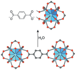 | ||
| Fig. 30 The ligand displacement mechanism and degradation of UiO-66 structure in the presence of water is similar to hydrolysis in the presence of acid. Reproduced from ref. 100 with permission from Advanced Materials. | ||
According to research using azolate-based linkers (e.g., pyrazolates), which form stronger metal bonds, is a suitable strategy for designing hydrolysis-resistant MOFs.117 Another method is to create kinetically stable MOFs. In this method, hydrolysis can be prevented by using SBUs with many connections, such as (Al(OH)(–COO)2)∞ or Zr6O4(OH)4(–COO)12. As Fig. 31 shows, in this method, with the spatial screening of SBU by linkers, the hydrolysis reaction is not performed.117 Also, other methods such as the use of bulky binders or the use of inert cations such as Cr3 can also reduce the possibility of hydrolysis and provide the ability to use such MOFs for aqueous environments.143
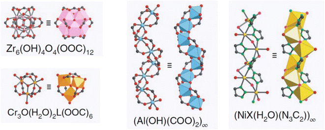 | ||
| Fig. 31 Examples of secondary building units (SBUs) that can stabilize MOFs in the presence of water. Reproduced from ref. 117 with permission from Nature nanotechnology. | ||
Zirconium-based MOFs with the presence of a hydrophilic group in their structure can show good performance as moisture absorbers. Among all zirconium MOFs, MOF-801 and MOF-841 can absorb water rapidly at low relative pressure. These MOFs have the possibility of easy desorption and are also stable in the presence of water.144 Similar results were obtained for MOF-UiO-66, which has smaller pores, but the organic groups in this MOF are not strong enough to absorb water at very low relative pressure. Stronger adsorption sites can be observed in MOFs with open metal sites, such as MOF-74, but similar to zeolites, these are very strong adsorption sites for water and require higher temperatures for the desorption stage of water molecules.144
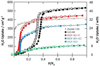 | ||
| Fig. 32 Water sorption isotherm of zirconium-based MOFs. Reproduced from ref. 144 with permission from American Chemical Society. | ||
According to Fig. 33, at P/P0 = 0.1 (blue color), the water absorption rate of MOF-801-P and MOF-74 is more than 20% wt, which performs better than other MOFs.144 In addition to stability in the presence of water, the MOF must exhibit high architectural stability to withstand the forces exerted on the porous walls during water desorption. While hydrolysis can be easily predicted based on chemical principles, architecture stability is difficult to predict and must be determined experimentally. The best way to measure MOF stability in operational conditions is water absorption and desorption cycle testing, which examines both stability in the presence of water and architecture.117 Most important is the stability in cycling, after the first cycle, these capacities are still 3 times higher than zeolite 13×. As mentioned, Co-MOF-74 needs a higher temperature to desorb water molecules, so MOF-801 has the best performance here.144
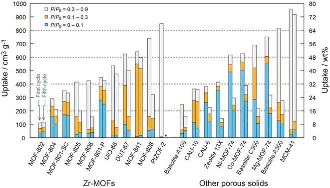 | ||
| Fig. 33 Water sorption capacity of zirconium-based MOF (left) and other porous materials (right) in different pressures. Reproduced from ref. 144 with permission from American Chemical Society. | ||
The components and structure of MOF-801, which is the first MOF used in the atmospheric water sorption device, showed in Fig. 34.
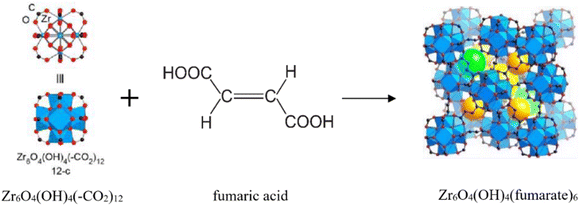 | ||
| Fig. 34 MOF-801 structure. Yellow, orange, and green balls represent the free space in MOF-801. Reproduced from ref. 144 with permission from American Chemical Society. | ||
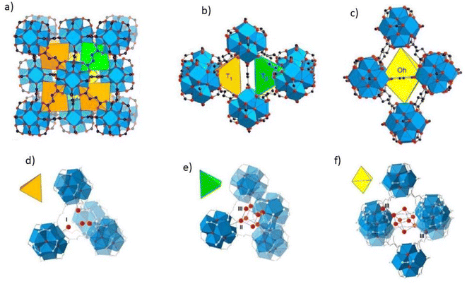 | ||
| Fig. 35 (a) The structure of MOF-801 includes three types of asymmetric porosity. (b) Two types of tetragonal porosity, T1 and T2. (c) octagonal porosity. (d) and (e) Water molecules are initially adsorbed in tetrahedral pores through hydrogen bonding with SBUs (sites I and II) and between them (sites III). (f) octagonal cavities are also filled and several adsorption sites have been identified and form hydrogen bonds with site III. Reproduced from ref. 144 with permission from American Chemical Society. | ||
3.3.7.1 Introducing MOF-303. Al(OH)(HPDC), which is MOF-303, has been synthesized by using aluminum instead of zirconium as a metal and using water instead of organic solvents, in which azolate (pyrazolate) based linkers with the formula of 3,5-pyrazoledicarboxylic acid monohydrate is used. Pyrazolates form stronger metal bonds that prevent MOF hydrolysis. MOF-303 has an xhh topology and consists of an unlimited number of A as SBUs connected through HPDC ligands. This structure has one-dimensional hydrophilic pores with a diameter of 6 Å.116 In addition to the high-performance adsorption isotherm that meets all the prerequisites for a water-absorbent material, this material has a completely open structure that allows the free passage of water molecules. The absorption capacity of this material is 40 wt% in 20–40% relative humidity and ambient temperature, which has been tested in 150 cycles of water absorption and desorption without any degradation.116 Fathieh et al.114 combined MOF-303 with 33 wt% of porous graphite in order to increase the absorption and improve the thermophysical properties, and it increased the production of water by 114%.
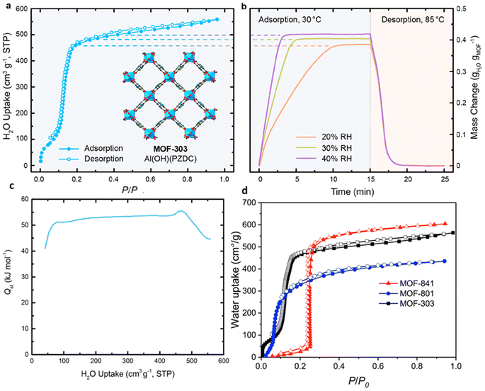 | ||
| Fig. 36 Water adsorption properties of MOF-303. (a) Water adsorption isotherm at 30 °C. (b) Water vapor adsorption & desorption behavior. (c) Isosteric heat of adsorption (Qst) for MOF-303. Reproduced from ref. 116 with permission from ACS central science. (d) Water adsorption isotherm of MOF-303 compared to other hydrophilic MOFs. Reproduced from ref. 101 with permission from ACS central science. | ||
The isosteric enthalpy of adsorption, Qst, of adsorption is essential for many applications, including absorption heating and cooling, because it determines the amount of energy required for these systems.
Since the enthalpy of absorption is usually higher than the latent heat of evaporation, it is important to investigate the enthalpy of adsorption and the isosteric heat of absorption in moisture absorbent systems.146 The isosteric heat of absorption of this material is 52 kj mol−1, which enables high work capacity and easy regeneration.116 The isosteric heat of adsorption (Qst) measures the enthalpy change when adsorbent molecules are adsorbed from the gas phase bulk to the adsorbent.147 Also, due to the presence of SBUs based on aluminum, MOF-303 does not change in the capacity of this material after 150 absorption and desorption cycles, which indicates hydrolytic stability. Fig. 37 shows SEM image of MOF-303 crystals.
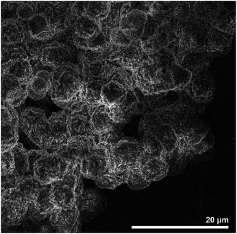 | ||
| Fig. 37 SEM image of MOF-303 crystals. Reproduced from ref. 116 with permission from ACS central science. | ||
The results of the absorption test on this MOF with the help of a thermometric analyzer (TGA) showed under humid air flow showed that MOF-303 is completely saturated RH = 20% after 10 minutes, at RH = 30% after 5 minutes, and at RH = 40% saturated after 3 minutes. Then, it completely desorbs within a few minutes at a temperature of 85 °C.116
3.4 Sorption-based water harvesting devices
Generally, sorption devices for water harvesting from air are classified into active and passive types. If the system works with natural energy and does not need a power source, it is called a passive device. In this type of device, there is a cycle in 24 hours, so that moisture is absorbed at night and desorbed during the day with solar heat and then distilled. In active systems, several absorption and desorption cycles can occur in one day. In this system, water production can be increased, but the energy consumption is also impressive. Discontinuous systems can be designed in two methods.148 In the first method, the absorbent bed is located at the bottom of a box that has a sloping cover. After absorbing moisture at night, desorption occurs with sunlight during the day, and water vapor moves upward, then it is distilled due to heat transfer on the inclined glass surface. With the accumulation of drops and their movement towards the slope, water is collected in the source. This method does not require any external energy and the system is completely passive. One of the challenges of this method is the accumulation of water droplets on the glass, which prevents the penetration of sunlight.149 Song et al.113 used this system to conduct the moisture absorption test from the air. First, the absorption stage was performed by placing the absorbent in the atmosphere, and then by closing the device and exposing it to sunlight, the water was desorbed and condensed. Almost 100% of the adsorbed water condensed on the inner wall of the system within 15 minutes, which indicates the fast adsorption kinetics. Tao et al.150 focused on the possibility of complete water removal and increasing the kinetics of removal in MOFs, was able to produce more water with less energy consumption (1.57 kW h LH2O−1). They were able to produce 1.95 LH2O kgCAS−1 day−1 of water at a relative humidity of 28 to 38%. By embedding a carbon scaffold (CS) in an Al-fumarate MOF monolith with abundant microchannels, they were able to increase the desorption rate and thus collect more water. Talaat et al.151 used a cone-shaped fabric layer soaked in CaCl2 solution as an absorbent substrate. At night, the absorber placed on the conical surface is exposed to the atmosphere to absorb water vapor. During the day, the absorber is tightly closed with a double-sided conical transparent surface and is directly exposed to sunlight to absorb water vapor. They were able to harvest 0.63 kg m−2 day−1 of water with this method. In another method of designing passive discontinuous systems, the absorbent bed is located in the upper part of the device and the condenser is in the lower part, and with the release of water vapor in the air, the mass is transferred from the bed to the condenser, but if the device is built on a large scale, mass transfer will occur with difficulty.152 Kim et al.115 designed a device to harvesting water from desert air and placed the absorbent bed on top and the condenser on the bottom, at RH = 20–40% and was able to deliver more than 0.25 Lwater kgMOF−1 day−1. Fathieh et al.114 by designing a water production device, with a different approach where water vapor was condensed in a glass chamber around the absorbent bed, were able to produce 78 grams of water per 0.825 kg of mof-801 and graphite mix. Since the mof can only absorb water and accommodate it in its pores, the resulting water was reported to be completely pure. By increasing the number of absorption substrates, absorption systems can work semi-continuously by creating a phase difference. Lapotin et al.153 designed a two-stage device with a commercial zeolite adsorbent (AQSOA Z01) to produce water from air moisture. In this device, the latent heat of condensation is circulated from the upper stage, to help the desorption of the second stage at the bottom. They were able to produce 0.77 kgwater m−2 day−1 of water, which was about a 2-fold increase in productivity compared to the single-stage mode. Wang et al.154 also used two adsorbent beds in the design of the water harvesting device. The beds were operated alternately in water absorption and release mode to achieve continuous water production. In another study, Xu et al.155 designed a device with four absorbent beds consisting of LiCl@rGO-SA and was able to produce 2120 mLwater kgsorbent−1 day−1 of water using solar energy. A device with four beds, each with a length of L1 (S1 in Fig. 38), where the three absorbent beds that are exposed to the ambient air absorb moisture from the air using convection displacement. The fourth and uppermost absorbent bed, exposed to sunlight, desorbs water vapor downwards, where the condensation process occurs. The advanced design of this device increases the air flow, improving the air flow throughout the condenser can help reduce power consumption, and the temperature difference between the condenser and the environment is reduced by more than 10 °C compared to the passive system. By increasing the number of absorption beds and reducing their length (L2 and L3 in S2 and S3 in Fig. 38), the kinetics of desorption and thus the efficiency of the device can be increased, which is achieved by moving faster between the absorption beds. Also, increasing the number of solar energy absorber plates around the device also helps to increase the absorption kinetics. However, each time switching to the next bed and heating and cooling the adsorbent bed can cause energy waste.156 Almassad et al.157 made a device based on MOF-801 and containing eight absorbent trays to produce water from air humidity. According to reports, this device has been able to produce 0.7–1.3 LH2O kgMOF−1 day−1 of water at a relative humidity of 10–32%. The power consumption for this device is reported to be 1.67–5.25 kW h LH2O−1. Hanikel et al.116 used a system with 10 adsorbent beds to produce water from air and was able to produce 0.7 l kgMOF−1 day−1. This system produced water from air outside the operating range of compression systems and in dry conditions of RH = 10% and temperature of 27 °C (related to dew point −4 °C). In a different design, Li et al.95 loaded the adsorbent on a rotating cylinder. With the penetration of sunlight on the top of the device, water vapor is absorbed from the surface of the cylinder and condenses on the inner sides of the condenser. The rotation speed of the cylinder has an important effect on the amount of water produced. Different rotation speeds were tested at 60% RH and 22 °C. The highest amount of water extraction was related to the rotation speed of 0.75 rph, which produced 1.25 g of water after 4 hours. The improved S5 in Fig. 38 is the same type of design. The absorbent surface in the S5 device is more than twice the absorbent surface in the S4. Also, device S5 compared to S4 provides a better ratio between desorption area (E) and absorption area.156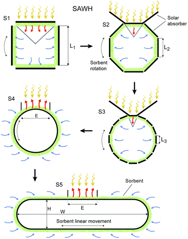 | ||
| Fig. 38 Schematic of semi-active systems. Reproduced from ref. 156 with permission from Energy & Environmental Science. | ||
In semi-continuous systems, the cycle time, when a complete cycle including absorption and resorption is performed, is an important and influential parameter. To maximize the daily water production capacity, it is very important to optimize the cycle time and increase the number of cycles. For this purpose, the full capacity of the absorbent may not be used for absorption. Therefore, fast adsorption kinetics is a more important factor than the final capacity of the adsorbent.116 Among the factors affecting the absorption kinetics, we can mention the relative humidity and temperature, which varies during the day and night. On the other hand, the kinetics of desorption is also affected by the rate of energy input to the system and the temperature of the condenser, which will not be constant if solar energy is used. Therefore, obtaining the optimal cycle time for multi-cycle systems should be determined based on the measurement of inlet temperature, relative humidity and condenser temperature. This means that a more complex and energy-intensive control system is required. Absorption kinetics is also affected by the temperature and relative humidity of the incoming air. While both of these parameters change during the day and night, they are not necessarily linearly related. However, the kinetics of desorption is also affected by the rate of energy input to the system and the temperature of the condenser. If solar energy is used, these two factors will not be constant. Therefore, the optimum constant cycle time cannot be found for multi-cycle systems and the cycle time must be actively determined based on measurements of inlet temperature, relative humidity, and condenser temperature. A summary of what was discussed can be seen in Table 5.
| Desiccant | Type | T °C | RH% | Water harvesting rate | Unit power | Device | Reference |
|---|---|---|---|---|---|---|---|
| MOF-derived nanoporous carbon | Passive | — | 30% | 0.18, Lwater kgcarbon−1 h−1 | Solar, 1 kW m−2 |  |
113 |
| CS/Al-Fum/SA | Passive | 25 | 33% | 1.95, LH2O kgCAS−1 day−1 | 1.57 kW h LH2O−1 |  |
150 |
| CaCl2 | Passive | — | — | 0.63 kg m−2 day−1 | Solar |  |
151 |
| LiCl/MgSO4/ACF composite | Passive | — | 35% | 0.92 gwater gadsorbent−1 |  |
152 | |
| MOF-801 | Passive | 20 | 30% | 0.25, Lwater kgMOF−1 day−1 | Solar |  |
115 |
| MOF-801 | Passive | 25 | 20% | 2.8, Lwater kgMOF−1 day−1 | Solar |  |
36 |
| MOF-801/G | Passive | 25 | 15% | 100 grwater kgMOF−1 day−1 | Solar | 114 | |
| Zeolite (AQSOA Z01) | Active | 25 | 15–20% | 0.77, L m−2 day−1 | Solar | 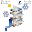 |
153 |
| Lithium chloride in silica sol | Active | 31 | 66–93% | 0.67 gwater gsorbent−1 h−1 | Solar |  |
154 |
| LiCl@rGO-SA | Active | — | 15–30% | 2120 mLwater kgsorbent−1 day−1 | Solar 0.95–1.05 kW m−2 | 155 | |
| MOF-801 | Active | — | 17–32% | 3.5, LH2O kgMOF−1 day−1 | 1.67–5.25 kW h LH2O−1 |  |
157 |
| MOF-303 | Active | 27 | 10% | 0.7, Lwater kgMOF−1 day−1 | Solar | 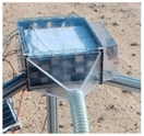 |
116 |
| 27 | 32% | In desert, 1.3, Lwater kgMOF−1 day−1 | |||||
| HCS-LiCl@SiO2 | Active | — | 60% | 1.6 kgwater kgsorbent−1 | Solar, 1 kW m−2 | 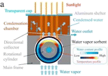 |
95 |
4 Concluding remarks
4.1 Summary
Among the proposed methods for extracting water from air humidity, the amount of water produced for compression technologies using VCC is more than other technologies. Condensation technologies can operate continuously and thus their WHRs are relatively high. However, to overcome the latent heat of water (2450 kj kg−1 at 20 °C), a large amount of energy is used by cooling, which increases the cost of the water obtained. Also, these methods work in high relative humidity and cannot be used in dry areas. Because as the relative humidity of the air decreases, the dew point temperature also decreases and in this case the temperature difference between the environment and the dew point temperature increases and as a result, the condenser has to do more work to cool the air containing water vapor, which means more energy consumption. This makes these technologies not economically viable for use in arid and semi-arid regions. In contrast, absorption technologies are not limited by geographical and climatic conditions. Due to their hydrophilicity, these systems automatically trap water vapor in the air. The main advantage of these systems is to increase the pressure by using thermal energy at low temperatures to replace the mechanical work of the compressor. This advantage allows absorption systems to operate using cheap and clean energy such as solar energy instead of electricity. Compared to other methods, the most important feature of absorption-based systems is the ability to produce water at low relative humidity. Depending on the type of absorber, these systems can produce water even in the desert. In recent years, the use of absorption technology to produce water from air humidity has been the subject of research by prestigious scientific centers in the world. As mentioned, one of the inexpensive absorbents are hygroscopic salts, such as LiCl or CaCl2, which can absorb water at low relative humidity. But these salts tend to liquefy (they liquefy by absorbing moisture from the air), which leads to leakage and ultimately causes corrosion of the water production unit. To overcome this problem, salt impregnation on a porous matrix has been proposed, but with only limited success in preventing material leakage and agglomeration of salt particles. Another proposed option is to use concentrated salt solutions that act as liquid adsorbents, but they usually require a complex apparatus, high capital costs, and careful management. Silica gels are also known as moisture absorbers, but these materials do not have the ability to absorb water vapor in low relative humidity. Zeolites are also known as hydrophilic materials, but they require a lot of energy for the desorption stage. While most of the proposed adsorbents do not have the ability to absorb moisture in a dry and desert environment, metal–organic frameworks (MOF) can be suitable candidates for this purpose. These materials have high chemical stability in water, suitable hydrophilicity, adjustable pore diameter and high specific surface area, and can collect water from dry air with low energy consumption.4.2 Basic challenges
Studies have shown that:● MOF structures can be designed to have an appropriate balance between hydrophobic and hydrophilic moieties. In such a way that it is so hydrophilic that it can absorb water vapor in low relative humidity, and it is also so hydrophobic that it desorbs the absorbed water with the minimum required energy.
● MOFs due to the thermal and chemical stability of their structures, in hundreds of adsorption and desorption cycle experiments, they are still stable in water and maintain their structure.
● The MOF powder is not 100% exposed to air and therefore the full absorption potential of the MOF is not used in the water absorption cycle. As a result, MOF adsorbents still have the potential to multiply their water output, provided that the MOF materials are maximally exposed to air with appropriate substrate embedding.
● By using MOF-based water absorbent devices, we have the potential to provide potable water at any time of the year and with any type of weather. With the development and progress of these systems, the current problem of the world, which is the lack of drinking water, can be solved because these systems can be easily provided to all people who live in urban or rural areas, as well as remote parts of the world.
4.3 Looking to the future
To develop this science, the following topics can be suggested:● Investigation of various parameters on the synthesis of MOFs in order to achieve greater porosity, lower cost and faster speed.
● The synthesis of MOFs has always been associated with high energy and cost. Therefore, if we can replace toxic materials such as DMF, and use water as a solvent in the synthesis, we can reduce costs on an industrial scale. This has been done in the synthesis of aluminum fumarate MOF.
● Investigating the parameters affecting the hydrophilicity and hydrophobicity of MOFs to achieve combined hydrophilicity and hydrophobicity and faster absorption and desorption.
● Construction and design of MOF-based atmospheric water production device with the installation of a suitable substrate so that MOF materials are maximally exposed to air and absorb with low energy.
● According to the new generation of active devices, obtaining absorbent material with fast absorption kinetics can lead us to higher efficiency and more water production per day.
● Another point is to use a desiccant that can not only be stable in several absorption and desorption cycles, but also not lose its absorption capacity and water absorption and desorption have little effect on MOFs cavities.
● As mentioned, the design of the active device can multiply the efficiency, however, the control of semi-continuous systems is very complicated, especially when solar energy is used, because it varies during the day and night.
● In the selection of the adsorbent, the kinetics of removal is also very important, because with the change of input energy, the speed of water removal can change and has an important effect on the final yield.
Data availability
The datasets used and analyzed during the current study available from the corresponding author on reasonable request.Conflicts of interest
The authors have no conflicts of interest to declare.References
- M. W. Logan, S. Langevin and Z. Xia, Reversible atmospheric water harvesting using metal-organic frameworks, Sci. Rep., 2020, 10(1), 1–11 CrossRef PubMed.
- S. H. Schneider, Encyclopedia of Climate and Weather, Oxford University Press, 2011 Search PubMed.
- P. Greve, et al., Global assessment of water challenges under uncertainty in water scarcity projections, Nat. Sustain., 2018, 1(9), 486–494 CrossRef.
- N. Wanders and Y. Wada, Human and climate impacts on the 21st century hydrological drought, J. Hydrol., 2015, 526, 208–220 CrossRef.
- V. G. Gude, Desalination and water reuse to address global water scarcity, Rev. Environ. Sci. Biotechnol., 2017, 16(4), 591–609 CrossRef.
- J. Imbrogno, J. J. Keating IV, J. Kilduff and G. Belfort, Critical aspects of RO desalination: A combination strategy, Desalination, 2017, 401, 68–87 CrossRef CAS.
- R. M. Downs and F. A. Day, National Geographic Almanac of Geography, National Geographic Society, 2005 Search PubMed.
- J. Margat and J. Van der Gun, Groundwater Around the World: A Geographic Synopsis. Crc Press, 2013 Search PubMed.
- L. Alberti, M. Cantone, L. Colombo, G. Oberto and I. La Licata, Assessment of aquifers groundwater storage for the mitigation of climate change effects, Rend. Online Soc. Geol. Ital., 2016, 39, 89–92 Search PubMed.
- T. Odeh, A. H. Mohammad, H. Hussein, M. Ismail and T. Almomani, Over-pumping of groundwater in Irbid governorate, northern Jordan: A conceptual model to analyze the effects of urbanization and agricultural activities on groundwater levels and salinity, Environ. Earth Sci., 2019, 78(1), 1–12 CrossRef.
- S. M. Hosseini, E. Parizi, B. Ataie-Ashtiani and C. T. Simmons, Assessment of sustainable groundwater resources management using integrated environmental index: Case studies across Iran, Sci. Total Environ., 2019, 676, 792–810 CrossRef CAS PubMed.
- A. Gautam, S. Rai, S. Rai and K. Ram, Impact of anthropogenic and geological factors on groundwater hydrochemistry in the unconfined aquifers of Indo-Gangetic plain, Phys. Chem. Earth, 2022, 126, 103109 CrossRef.
- S. Al Arni, S. Ghareba, C. Solisio, M. S. Alves Palma and A. Converti, Methods of reactive red 141 dye decolorization, treatment, and removal from industrial wastewaters: a critical review, Environ. Eng. Sci., 2021, 38(7), 577–591 CrossRef CAS.
- S. Al Arni, M. Elwaheidi, A. A. Salih, D. Ghernaout and M. Matouq, Greywater reuse: a review of the Jordanian experience in rural communities, Water Sci. Technol., 2022, 85, 1952–1963 CrossRef CAS PubMed.
- E. Tilley, Compendium of Sanitation Systems and Technologies, Eawag, 2014 Search PubMed.
- O. R. Al-Jayyousi, Greywater reuse: towards sustainable water management, Desalination, 2003, 156(1–3), 181–192 CrossRef CAS.
- K. Wydra, P. Becker and H. A. Aulich, Sustainable solutions for solar energy driven drinking water supply for rural settings in Sub-Saharan Africa: a case study of Nigeria, J. Photonics Energy, 2019, 9(4), 043106 CAS.
- L. L. Dodson and J. Bargach, Harvesting fresh water from fog in rural Morocco: research and impact Dar Si Hmad's Fogwater Project in Aït Baamrane, Procedia Eng., 2015, 107, 186–193 CrossRef.
- M. V. Marzol and J. Sánchez, Fog water harvesting in Ifni, Morocco. An assessment of potential and demand, Die Erde, 2008, 139(1–2), 97–119 Search PubMed.
- J. K. Domen, W. T. Stringfellow, M. K. Camarillo and S. Gulati, Fog water as an alternative and sustainable water resource, Clean Technol. Environ. Policy, 2014, 16(2), 235–249 CrossRef.
- W. Ma, A. Soroush, T. V. A. Luong and M. S. Rahaman, Cysteamine-and graphene oxide-mediated copper nanoparticle decoration on reverse osmosis membrane for enhanced anti-microbial performance, J. Colloid Interface Sci., 2017, 501, 330–340 CrossRef CAS PubMed.
- T. A. Dankovich and D. G. Gray, Bactericidal paper impregnated with silver nanoparticles for point-of-use water treatment, Environ. Sci. Technol., 2011, 45(5), 1992–1998 CrossRef CAS PubMed.
- P. Redfield, Fluid technologies: The Bush Pump, the LifeStraw® and microworlds of humanitarian design, Soc. Stud. Sci., 2016, 46(2), 159–183 CrossRef PubMed.
- J. Yang, et al., A moisture-hungry copper complex harvesting air moisture for potable water and autonomous urban agriculture, Adv. Mater., 2020, 32(39), 2002936 CrossRef CAS PubMed.
- J. H. Humphrey, et al., The potential for atmospheric water harvesting to accelerate household access to safe water, Lancet Planet. Health, 2020, 4(3), e91–e92 CrossRef PubMed.
- S. A. Ibrahim, Conductivity behavior for the permeate stream of reverse osmosis water in thermal power station, J. Eng. Sustain. Dev., 2019, 23(01), 80–92 CrossRef.
- M. Elimelech and W. A. Phillip, The future of seawater desalination: energy, technology, and the environment, Science, 2011, 333(6043), 712–717 CrossRef CAS PubMed.
- J. J. Sadhwani, J. M. Veza and C. Santana, Case studies on environmental impact of seawater desalination, Desalination, 2005, 185(1–3), 1–8 CrossRef CAS.
- H. D. Ibrahim and E. A. Eltahir, Impact of brine discharge from seawater desalination plants on persian/arabian gulf salinity, J. Environ. Eng., 2019, 145(12), 04019084 CrossRef.
- W. Al-Zubari, A. ElSadek and M. Khadim, Environmental Impacts of Seawater Desalination on the Marine Environment in the Kingdom of Bahrain, J. Eng. Res., 2021, 27(1), 1 Search PubMed.
- G. E. William, M. Mohamed and M. Fatouh, Desiccant system for water production from humid air using solar energy, Energy, 2015, 90, 1707–1720 CrossRef CAS.
- D. Milani, A. Qadir, A. Vassallo, M. Chiesa and A. Abbas, Experimentally validated model for atmospheric water generation using a solar assisted desiccant dehumidification system, Energy Build., 2014, 77, 236–246 CrossRef.
- A. Mulchandani and P. Westerhoff, Geospatial climatic factors influence water production of solar desiccant driven atmospheric water capture devices, Environ. Sci. Technol., 2020, 54(13), 8310–8322 CrossRef CAS PubMed.
- R. V. Wahlgren, Atmospheric water vapour processor designs for potable water production: a review, Water Res., 2001, 35(1), 1–22 CrossRef CAS PubMed.
- A. R. Parker and C. R. Lawrence, Water capture by a desert beetle, Nature, 2001, 414(6859), 33–34 CrossRef CAS PubMed.
- H. Kim, et al., Water harvesting from air with metal-organic frameworks powered by natural sunlight, Science, 2017, 356(6336), 430–434 CrossRef CAS PubMed.
- J. Canivet, A. Fateeva, Y. Guo, B. Coasne and D. Farrusseng, Water adsorption in MOFs: fundamentals and applications, Chem. Soc. Rev., 2014, 43(16), 5594–5617 RSC.
- A. Magrini, L. Cattani, M. Cartesegna and L. Magnani, Water production from air conditioning systems: some evaluations about a sustainable use of resources, Sustainability, 2017, 9(8), 1309 CrossRef.
- R. Tu and Y. Hwang, Reviews of atmospheric water harvesting technologies, Energy, 2020, 201, 117630 CrossRef.
- I. Al Keyyam, M. D. Al-Nimr, S. Khashan and A. Keewan, A new solar atmospheric water harvesting integrated system using CPV/T–Stirling engine–Absorption cooling cycle and vapor compression refrigeration cycle, Int. J. Energy Res., 2021, 45(11), 16400–16417 CrossRef CAS.
- A. Tripathi, S. Tushar, S. Pal, S. Lodh, S. Tiwari and R. Desai, Atmospheric water generator, Int. J. Enhanc. Res. Sci., 2016, 5(4), 69–72 Search PubMed.
- L. Yang, Study of Refrigeration System on Water Production through Cooling Air, Tianjin University of Commerce, 2013, vol. 61, pp. 1772–1778 Search PubMed.
- S. Zolfagharkhani, M. Zamen and M. M. Shahmardan, Thermodynamic analysis and evaluation of a gas compression refrigeration cycle for fresh water production from atmospheric air, Energy Convers. Manage., 2018, 170, 97–107 CrossRef.
- A. Magrini, L. Cattani, M. Cartesegna and L. Magnani, Integrated systems for air conditioning and production of drinking water–Preliminary considerations, Energy Procedia, 2015, 75, 1659–1665 CrossRef.
- B. Tashtoush and M. Bani Younes, Comparative thermodynamic study of refrigerants to select the best environment-friendly refrigerant for use in a solar ejector cooling system, Arab J. Sci. Eng., 2019, 44(2), 1165–1184 CrossRef CAS.
- Y. A. Nazarova, How to solve water shortage problem by means of renewable power generation?, Int. J. Energy Econ. Policy, 2019, 9, 330–335 Search PubMed.
- J. Solís-Chaves, C. Rocha-Osorio, A. Murari, V. M. Lira and A. J. Sguarezi Filho, Extracting potable water from humid air plus electric wind generation: A possible application for a Brazilian prototype, Renewable Energy, 2018, 121, 102–115 CrossRef.
- W. Yue, Y. Xue and Y. Liu, High humidity aerodynamic effects study on offshore wind turbine airfoil/blade performance through CFD analysis, Int. J. Rotating Mach., 2017, 2017(15), 1 Search PubMed.
- J. Luo, W. Zhang and X. Bai, Development and application of a field water maker, J. Heat., Vent. Air Cond., 2004, 34(4), 42–45 Search PubMed.
- R. Zhang, R. Zang and J. Liu, Study on properties of water extraction from cooled air system under all operating conditions, Cryog. Supercond., 2016, 44(1), 51–55 Search PubMed.
- H. Elattar, A. Fouda and S. Nada, Performance investigation of a novel solar hybrid air conditioning and humidification–dehumidification water desalination system, Desalination, 2016, 382, 28–42 CrossRef CAS.
- W. A. SALAH and M. Abuhelwa, Review of thermoelectric cooling devices recent applications, J. Eng. Sci. Technol., 2020, 15(1), 455–476 Search PubMed.
- D. Enescu and E. O. Virjoghe, A review on thermoelectric cooling parameters and performance, Renew. Sustain. Energy Rev., 2014, 38, 903–916 CrossRef.
- V. Joshi, V. Joshi, H. Kothari, M. Mahajan, M. Chaudhari and K. Sant, Experimental investigations on a portable fresh water generator using a thermoelectric cooler, Energy Procedia, 2017, 109, 161–166 CrossRef.
- F. Tajeddini, M. Eslami, and N. Etaati, Thermodynamic analysis and optimization of water harvesting from air using thermoelectric coolers, in Proceedings of the ISME2018, 26rd International Conference on Mechanical, Semnan, Iran, 2018, vol. 26, pp. 24–26 Search PubMed.
- M. Jradi, N. Ghaddar and K. Ghali, Experimental and theoretical study of an integrated thermoelectric–photovoltaic system for air dehumidification and fresh water production, Int. J. Energy Res., 2012, 36(9), 963–974 CrossRef CAS.
- F. Tajeddini, M. Eslami and N. Etaati, Thermodynamic analysis and optimization of water harvesting from air using thermoelectric coolers, J. Energy Convers. Manag., 2018, 174, 417–429 CrossRef.
- S. Liu, et al., Experimental analysis of a portable atmospheric water generator by thermoelectric cooling method, Energy Procedia, 2017, 142, 1609–1614 CrossRef.
- K. Pontious, B. Weidner, N. Guerin, O. Pierrakos, and K. Altaii, Design of an atmospheric water generator: Harvesting water out of thin air, in 2016 IEEE Systems and Information Engineering Design Symposium (SIEDS), IEEE, 2016, pp. 6–11 Search PubMed.
- T. Miyazaki, A. Akisawa and T. Kashiwagi, The effects of solar chimneys on thermal load mitigation of office buildings under the Japanese climate, Renew. Energy, 2006, 31(7), 987–1010 CrossRef CAS.
- X. Zhou, F. Wang and R. M. Ochieng, A review of solar chimney power technology, Renew. Sustain. Energy Rev., 2010, 14(8), 2315–2338 CrossRef.
- T. Ming, T. Gong, R. K. de Richter, Y. Wu and W. Liu, A moist air condensing device for sustainable energy production and water generation, Energy Convers. Manage., 2017, 138, 638–650 CrossRef.
- T. Ming, T. Gong, R. K. de Richter, W. Liu and A. Koonsrisuk, Freshwater generation from a solar chimney power plant, Energy Convers. Manage., 2016, 113, 189–200 CrossRef.
- J. Lindblom and B. Nordell, Condensation irrigation a system for desalination and irrigation, in World Renewable Energy and Environmental Conference: Abstract Book, 2006 Search PubMed.
- J. Lindblom and B. Nordell, Water production by underground condensation of humid air, Desalination, 2006, 189(1–3), 248–260 CrossRef CAS.
- A. Göhlman, Heating of frozen ground.(Uppvärmning av frusen mark), Unpublished Master thesis, Luleå University of Technology, Lulea, Sweden, 1987 Search PubMed.
- K. Liu, X. Yao and L. Jiang, Recent developments in bio-inspired special wettability, Chem. Soc. Rev., 2010, 39(8), 3240–3255 RSC.
- T. Young, III. An essay on the cohesion of fluids, Philos. Trans. R. Soc., 1805, 95, 65–87 CrossRef.
- R. N. Wenzel, Surface roughness and contact angle, J. Phys. Chem., 1949, 53(9), 1466–1467 CrossRef CAS.
- A. Cassie and S. Baxter, Wettability of porous surfaces, Trans. Faraday Soc., 1944, 40, 546–551 RSC.
- S. Zhang, J. Huang, Z. Chen and Y. Lai, Bioinspired special wettability surfaces: from fundamental research to water harvesting applications, Small, 2017, 13(3), 1602992 CrossRef PubMed.
- Y. Zheng, et al., Directional water collection on wetted spider silk, Nature, 2010, 463(7281), 640–643 CrossRef CAS PubMed.
- K.-C. Park, et al., Condensation on slippery asymmetric bumps, Nature, 2016, 531(7592), 78–82 CrossRef CAS PubMed.
- R. Seth, Beetle Juice Inspired, Product Design, 2010 Search PubMed.
- A. A. Salehi, M. Ghannadi-Maragheh, M. Torab-Mostaedi, R. Torkaman and M. Asadollahzadeh, A review on the water-energy nexus for drinking water production from humid air, Renew. Sustain. Energy Rev., 2020, 120, 109627 CrossRef.
- P. Moazzam, H. Tavassoli, A. Razmjou, M. E. Warkiani and M. Asadnia, Mist harvesting using bioinspired polydopamine coating and microfabrication technology, Desalination, 2018, 429, 111–118 CrossRef CAS.
- K. J. Lucier and M. Qadir, Gender and community mainstreaming in fog water collection systems, Water, 2018, 10(10), 1472 CrossRef.
- L. T. Nguyen, et al., Three-dimensional multilayer vertical filament meshes for enhancing efficiency in fog water harvesting, ACS Omega, 2021, 6(5), 3910–3920 CrossRef CAS PubMed.
- O. Klemm, et al., Fog as a fresh-water resource: overview and perspectives, Ambio, 2012, 41(3), 221–234 CrossRef PubMed.
- L. Jones, Four roads to fresh water [water engineering projects in the developing world], Eng. Technol., 2017, 12(5), 64–66 CrossRef.
- G. Morichi, L. B. Calixto and A. Zanelli, Novel Applications for Fog Water Harvesting, J. geosci. environ. Prot., 2018, 6(3), 26–36 Search PubMed.
- X. Zhou, H. Lu, F. Zhao and G. Yu, Atmospheric water harvesting: a review of material and structural designs, ACS Mater. Lett., 2020, 2(7), 671–684 CrossRef CAS.
- Z. Chen, et al., Recent progress on sorption/desorption-based atmospheric water harvesting powered by solar energy, Sol. Energy Mater. Sol. Cells, 2021, 230, 111233 CrossRef CAS.
- R. Li, Y. Shi, M. Alsaedi, M. Wu, L. Shi and P. Wang, Hybrid hydrogel with high water vapor harvesting capacity for deployable solar-driven atmospheric water generator, Environ. Sci. Technol., 2018, 52(19), 11367–11377 CrossRef CAS PubMed.
- J. Xu, et al., Efficient solar-driven water harvesting from arid air with metal–organic frameworks modified by hygroscopic salt, Angew. Chem., Int. Ed., 2020, 59(13), 5202–5210 CrossRef CAS PubMed.
- T. Andronikashvili, T. Kordzakhia, and L. Eprikashvili, Zeolites the Unique Desiccating Agents of Organic Liquids, Lap Lambert Academic Publishing, 2015, p. 100 Search PubMed.
- M. Danilczuk, K. Długopolska, T. Ruman and D. Pogocki, Molecular sieves in medicine, Mini-Rev. Med. Chem., 2008, 8(13), 1407–1417 CrossRef CAS PubMed.
- H. Mittal, A. Al Alili and S. M. Alhassan, Adsorption isotherm and kinetics of water vapors on novel superporous hydrogel composites, Microporous Mesoporous Mater., 2020, 299, 110106 CrossRef CAS.
- H. Omidian, J. G. Rocca and K. Park, Advances in superporous hydrogels, J. Control Release, 2005, 102(1), 3–12 CrossRef CAS PubMed.
- L. Wang, R. Wang and R. Oliveira, A review on adsorption working pairs for refrigeration, Renew. Sustain. Energy Rev., 2009, 13(3), 518–534 CrossRef CAS.
- J. Libera, J. Elam and M. Pellin, Conformal ZnO coatings on high surface area silica gel using atomic layer deposition, Thin Solid Films, 2008, 516(18), 6158–6166 CrossRef CAS.
- A. Kabeel, Water production from air using multi-shelves solar glass pyramid system, Renewable energy, 2007, 32(1), 157–172 CrossRef CAS.
- A. LaPotin, H. Kim, S. R. Rao and E. N. Wang, Adsorption-based atmospheric water harvesting: impact of material and component properties on system-level performance, Acc. Chem. Res., 2019, 52(6), 1588–1597 CrossRef CAS PubMed.
- M. K. Alsaedi, "Atmospheric Water Harvesting by an Anhydrate Salt and Its Release by a Photothermal Process towards Sustainable Potable Water Production in Arid Regions, Master thesis, King Abdullah University of Science and Technology Thuwal, Kingdom of Saudi Arabia, 2018 Search PubMed.
- R. Li, Y. Shi, M. Wu, S. Hong and P. Wang, Improving atmospheric water production yield: Enabling multiple water harvesting cycles with nano sorbent, Nano Energy, 2020, 67, 104255 CrossRef CAS.
- J. Wang, J. Liu, R. Wang and L. Wang, Experimental investigation on two solar-driven sorption based devices to extract fresh water from atmosphere, Appl. Therm. Eng., 2017, 127, 1608–1616 CrossRef CAS.
- K. C. Chan, C. Y. Chao and C. Wu, Measurement of properties and performance prediction of the new MWCNT-embedded zeolite 13X/CaCl2 composite adsorbents, Int. J. Heat Mass Transfer, 2015, 89, 308–319 CrossRef CAS.
- F. Ni, et al., Collective behaviors mediated multifunctional black sand aggregate towards environmentally adaptive solar-to-thermal purified water harvesting, Nano Energy, 2020, 68, 104311 CrossRef CAS.
- W. Wang, L. Wu, Z. Li, Y. Fang, J. Ding and J. Xiao, An overview of adsorbents in the rotary desiccant dehumidifier for air dehumidification, Dry. Technol., 2013, 31(12), 1334–1345 CrossRef CAS.
- M. J. Kalmutzki, C. S. Diercks and O. M. Yaghi, Metal–organic frameworks for water harvesting from air, Adv. Mater., 2018, 30(37), 1704304 CrossRef PubMed.
- W. Xu and O. M. Yaghi, Metal–organic frameworks for water harvesting from air, anywhere, anytime, ACS Cent. Sci., 2020, 6(8), 1348–1354 CrossRef CAS PubMed.
- L. G. Gordeeva, et al., Metal-organic frameworks for energy conversion and water harvesting: A bridge between thermal engineering and material science, Nano Energy, 2021, 84, 105946 CrossRef CAS.
- P. Rocío-Bautista, I. Taima-Mancera, J. Pasán and V. Pino, Metal-organic frameworks in green analytical chemistry, Separations, 2019, 6(3), 33 CrossRef.
- X. S. Wang, L. Li, D. Li and J. Ye, Recent progress on exploring stable metal–organic frameworks for photocatalytic solar fuel production, Sol. RRL, 2020, 4(8), 1900547 CrossRef CAS.
- T. Pan, K. Yang and Y. Han, Recent progress of atmospheric water harvesting using metal-organic frameworks, Chem. Res. Chin. Univ., 2020, 36(1), 33–40 CrossRef CAS.
- N. C. Burtch, H. Jasuja and K. S. Walton, Water stability and adsorption in metal–organic frameworks, Chem. Rev., 2014, 114(20), 10575–10612 CrossRef CAS PubMed.
- A. Terzis, A. Ramachandran, K. Wang, M. Asheghi, K. E. Goodson and J. G. Santiago, High-frequency water vapor sorption cycling using fluidization of metal-organic frameworks, Cell Rep. Phys. Sci., 2020, 1(5), 100057 CrossRef.
- A. J. Rieth, S. Yang, E. N. Wang and M. Dinca, Record atmospheric fresh water capture and heat transfer with a material operating at the water uptake reversibility limit, ACS Cent. Sci., 2017, 3(6), 668–672 CrossRef CAS PubMed.
- G. Yilmaz, et al., Autonomous atmospheric water seeping MOF matrix, Sci. Adv., 2020, 6(42), eabc8605 CrossRef CAS PubMed.
- M. P. Silva, et al., Water vapor harvesting by a (P) TSA process with MIL-125 (Ti) _NH2 as adsorbent, Sep. Purif. Technol., 2020, 237, 116336 CrossRef CAS.
- F. Trapani, A. Polyzoidis, S. Löbbecke and C. G. Piscopo, On the general water harvesting capability of metal-organic frameworks under well-defined climatic conditions, Microporous Mesoporous Mater., 2016, 230, 20–24 CrossRef CAS.
- M. Silva, et al., MIL-160 (Al) MOF's potential in adsorptive water harvesting, Adsorption, 2021, 27(2), 213–226 CrossRef CAS.
- Y. Song, et al., High-yield solar-driven atmospheric water harvesting of metal–organic-framework-derived nanoporous carbon with fast-diffusion water channels, Nat. Nanotechnol., 2022, 17(8), 857–863 CrossRef CAS PubMed.
- F. Fathieh, M. J. Kalmutzki, E. A. Kapustin, P. J. Waller, J. Yang and O. M. Yaghi, Practical water production from desert air, Sci. Adv., 2018, 4(6), eaat3198 CrossRef PubMed.
- H. Kim, et al., Adsorption-based atmospheric water harvesting device for arid climates, Nat. Commun., 2018, 9(1), 1–8 CrossRef PubMed.
- N. Hanikel, et al., Rapid cycling and exceptional yield in a metal-organic framework water harvester, ACS Cent. Sci., 2019, 5(10), 1699–1706 CrossRef CAS PubMed.
- N. Hanikel, M. S. Prévot and O. M. Yaghi, MOF water harvesters, Nat. Nanotechnol., 2020, 15(5), 348–355 CrossRef CAS PubMed.
- A. H. Mashhadzadeh, et al., Metal–Organic Framework (MOF) through the lens of molecular dynamics simulation: current status and future perspective, J. Compos. Sci., 2020, 4(2), 75 CrossRef CAS.
- H. Li, K. Wang, Y. Sun, C. T. Lollar, J. Li and H.-C. Zhou, Recent advances in gas storage and separation using metal–organic frameworks, Mater. Today, 2018, 21(2), 108–121 CrossRef CAS.
- J. Xiao, M. Liu, F. Tian and Z. Liu, Stable Europium-Based Metal–Organic Frameworks for Naked-Eye Ultrasensitive Detecting Fluoroquinolones Antibiotics, Inorg. Chem., 2021, 60(7), 5282–5289 CrossRef CAS PubMed.
- S. Bai, X. Liu, K. Zhu, S. Wu and H. Zhou, Metal–organic framework-based separator for lithium–sulfur batteries, Nat. Energy, 2016, 1(7), 1–6 Search PubMed.
- G. Boix, et al., MOF-beads containing inorganic nanoparticles for the simultaneous removal of multiple heavy metals from water, ACS Appl. Mater. Interfaces, 2020, 12(9), 10554–10562 CrossRef CAS PubMed.
- P. He, K.-G. Haw, J. Ren, Q. Fang, S. Qiu and V. Valtchev, MOF–cation exchange resin composites and their use for water decontamination, Inorg. Chem. Front., 2018, 5(11), 2784–2791 RSC.
- Y. Ye, L. Gong, S. Xiang, Z. Zhang and B. Chen, Metal–organic frameworks as a versatile platform for proton conductors, Adv. Mater., 2020, 32(21), 1907090 CrossRef CAS PubMed.
- J. An, C. M. Shade, D. A. Chengelis-Czegan, S. Petoud and N. L. Rosi, Zinc-adeninate metal– organic framework for aqueous encapsulation and sensitization of near-infrared and visible emitting lanthanide cations, J. Am. Chem. Soc., 2011, 133(5), 1220–1223 CrossRef CAS PubMed.
- T. Toyao, et al., Development of a Ru complex-incorporated MOF photocatalyst for hydrogen production under visible-light irradiation, Chem. Commun., 2014, 50(51), 6779–6781 RSC.
- M. Samaniyan, M. Mirzaei, R. Khajavian, H. Eshtiagh-Hosseini and C. Streb, Heterogeneous catalysis by polyoxometalates in metal–organic frameworks, ACS Catal., 2019, 9(11), 10174–10191 CrossRef CAS.
- S. Yuvaraja, et al., Realization of an ultrasensitive and highly selective OFET NO2 sensor: the synergistic combination of PDVT-10 polymer and porphyrin–MOF, ACS Appl. Mater. Interfaces, 2020, 12(16), 18748–18760 CrossRef CAS PubMed.
- C. Dey, T. Kundu, B. P. Biswal, A. Mallick and R. Banerjee, Crystalline metal-organic frameworks (MOFs): synthesis, structure and function, Acta. Crystallogr. B, 2014, 70(1), 3–10 CrossRef CAS PubMed.
- N. Stock and S. Biswas, Synthesis of metal-organic frameworks (MOFs): routes to various MOF topologies, morphologies, and composites, Chem. Rev., 2012, 112(2), 933–969 CrossRef CAS PubMed.
- S. Qiu and G. Zhu, Molecular engineering for synthesizing novel structures of metal–organic frameworks with multifunctional properties, Coord. Chem. Rev., 2009, 253(23–24), 2891–2911 CrossRef CAS.
- W. Liang and D. M. D'Alessandro, Microwave-assisted solvothermal synthesis of zirconium oxide based metal–organic frameworks, Chem. Commun., 2013, 49(35), 3706–3708 RSC.
- J. Klinowski, F. A. A. Paz, P. Silva and J. Rocha, Microwave-assisted synthesis of metal–organic frameworks, Dalton Trans., 2011, 40(2), 321–330 RSC.
- L.-N. Jin, Q. Liu and W.-Y. Sun, An introduction to synthesis and application of nanoscale metal–carboxylate coordination polymers, CrystEngComm, 2014, 16(19), 3816–3828 RSC.
- M. Y. Masoomi, A. Morsali and P. C. Junk, Rapid mechanochemical synthesis of two new Cd (II)-based metal–organic frameworks with high removal efficiency of Congo red, CrystEngComm, 2015, 17(3), 686–692 RSC.
- J. Beamish-Cook, K. Shankland, C. A. Murray and P. Vaqueiro, Insights into the Mechanochemical Synthesis of MOF-74, Cryst. Growth Des., 2021, 21(5), 3047–3055 CrossRef CAS PubMed.
- F. C. Gennari and J. J. Andrade-Gamboa, A Systematic approach to the synthesis, thermal stability and hydrogen storage properties of rare-earth borohydrides, in Emerging Materials for Energy Conversion and Storage, Elsevier, 2018, ch. 13, pp. 429–459 Search PubMed.
- S. L. James, et al., Mechanochemistry: opportunities for new and cleaner synthesis, Chem. Soc. Rev., 2012, 41(1), 413–447 RSC.
- A. Martinez Joaristi, J. Juan-Alcañiz, P. Serra-Crespo, F. Kapteijn and J. Gascon, Electrochemical synthesis of some archetypical Zn2+, Cu2+, and Al3+ metal organic frameworks, Cryst. Growth Des., 2012, 12(7), 3489–3498 CrossRef CAS.
- N. Campagnol, E. R. Souza, D. E. De Vos, K. Binnemans and J. Fransaer, Luminescent terbium-containing metal–organic framework films: new approaches for the electrochemical synthesis and application as detectors for explosives, Chem. Commun., 2014, 50(83), 12545–12547 RSC.
- M. Al-Ghoul, R. Issa and M. Hmadeh, Synthesis, size and structural evolution of metal–organic framework-199 via a reaction–diffusion process at room temperature, CrystEngComm, 2017, 19(4), 608–612 RSC.
- A. E. Platero-Prats, A. Bermejo Gómez, L. Samain, X. Zou and B. Martín-Matute, The First One-Pot Synthesis of Metal–Organic Frameworks Functionalised with Two Transition-Metal Complexes, Eur. J. Chem., 2015, 21(2), 861–866 CrossRef CAS PubMed.
- Z. Chen, et al., Reticular access to highly porous acs-MOFs with rigid trigonal prismatic linkers for water sorption, J. Am. Chem. Soc., 2019, 141(7), 2900–2905 CrossRef CAS PubMed.
- H. Furukawa, et al., Water adsorption in porous metal–organic frameworks and related materials, J. Am. Chem. Soc., 2014, 136(11), 4369–4381 CrossRef CAS PubMed.
- F. Rodriguez-Reinoso, J. M. Martin-Martinez, C. Prado-Burguete and B. McEnaney, A standard adsorption isotherm for the characterization of activated carbons, J. Phys. Chem., 1987, 91(3), 515–516 CrossRef CAS.
- H. Kim, et al., Characterization of adsorption enthalpy of novel water-stable zeolites and metal-organic frameworks, Sci. Rep., 2016, 6(1), 1–8 CrossRef PubMed.
- H. Tun and C.-C. Chen, Isosteric heat of adsorption from thermodynamic Langmuir isotherm, Adsorption, 2021, 27(6), 979–989 CrossRef CAS.
- M. Ejeian and R. Wang, Adsorption-based atmospheric water harvesting, Joule, 2021, 5(7), 1678–1703 CrossRef.
- M. Kumar and A. Yadav, Experimental investigation of solar powered water production from atmospheric air by using composite desiccant material “CaCl2/saw wood”, Desalination, 2015, 367, 216–222 CrossRef CAS.
- Y. Tao, Q. Wu, C. Huang, D. Zhu and H. Li, Electrically heatable carbon scaffold accommodated monolithic metal–organic frameworks for energy-efficient atmospheric water harvesting, Chem. Eng. J., 2023, 451, 138547 CrossRef CAS.
- M. Talaat, M. Awad, E. Zeidan and A. Hamed, Solar-powered portable apparatus for extracting water from air using desiccant solution, Renewable energy, 2018, 119, 662–674 CrossRef CAS.
- M. Ejeian, A. Entezari and R. Wang, Solar powered atmospheric water harvesting with enhanced LiCl/MgSO4/ACF composite, Appl. Therm. Eng., 2020, 176, 115396 CrossRef CAS.
- A. LaPotin, et al., Dual-stage atmospheric water harvesting device for scalable solar-driven water production, Joule, 2021, 5(1), 166–182 CrossRef CAS.
- W. Wang, T. Yang, Q. Pan, Y. Dai, R. Wang and T. Ge, All-day freshwater production enabled by an active continuous sorption-based atmospheric water harvesting system, Energy Convers. Manage., 2022, 264, 115745 CrossRef CAS.
- J. Xu, et al., Ultrahigh solar-driven atmospheric water production enabled by scalable rapid-cycling water harvester with vertically aligned nanocomposite sorbent, Energy Environ. Sci., 2021, 14(11), 5979–5994 RSC.
- P. Poredoš, H. Shan, C. Wang, F. Deng and R. Wang, Sustainable water generation: Grand challenges in continuously atmospheric water harvesting, Energy Environ. Sci., 2022, 15, 3223–3235 RSC.
- H. A. Almassad, R. I. Abaza, L. Siwwan, B. Al-Maythalony and K. E. Cordova, Environmentally adaptive MOF-based device enables continuous self-optimizing atmospheric water harvesting, Nat. Commun., 2022, 13(1), 1–10 Search PubMed.
| This journal is © The Royal Society of Chemistry 2023 |

