DOI:
10.1039/D2RA07626H
(Paper)
RSC Adv., 2023,
13, 5013-5026
Highly efficient and stable AgI–CdO nanocomposites for photocatalytic and antibacterial activity†
Received
30th November 2022
, Accepted 30th January 2023
First published on 9th February 2023
Abstract
For the last several decades, semiconducting materials and nanocomposites have received a lot of interest in generating highly efficient photocatalysts to destroy organic pollutants and eradicate bacteria. This study uses a simple deposition and precipitation approach at ambient temperature to create a unique and efficient AgI–CdO heterojunction. DRS, IR, SEM, EDS, XRD, EIS, and TEM were utilized to identify the material. SEM and TEM investigation depict the completely spherical, hexagonal forms and zigzag cubes for synthesized AgI–CdO. The EDX spectra reveal the presence of Ag, I, Cd, and O elements without impurity peaks showing that the prepared samples are highly pure. The activity of the synthesized materials was tested by degrading two different chromophoric dyes and a drug derivative (paracetamol) in an aqueous suspension under visible light. In addition, the activity of the most active catalyst was compared with Degussa P25, Fenton's reagent, and under sunlight for degradation of MB and RhB under similar conditions. Photolysis of paracetamol was also looked at using HPLC to identify intermediates formed in the photo-oxidation process. In addition, antibacterial activity was also investigated with the synthesized CdO–AgI nanocomposite in vitro against human pathogenic bacterial strains and compared with that of pure materials like AgI and standard ampicillin. The results showed excellent activity with the composite material, which could be due to the higher surface areas and the interactions between AgI and CdO nanoparticles. Quenching investigations revealed O2˙− and holes are principal reactive species. A viable photocatalytic degradation mechanism for organic pollutant elimination over the AgI–CdO nanocomposite has been sketched out based on the obtained results.
1. Introduction
Contaminants, like pharmaceutical products, metals, and dyes in aquatic systems, pose a hazard to the environment and human health.1–8 Different strategies for removing inorganic and organic impurities from water have been developed. Heterogeneous photocatalysis is considered the most environmentally friendly and efficient technology for eliminating these contaminants.9–17 Semiconductors, for example, titanium dioxide, zinc oxide, zinc sulfide, and cadmium oxide are widely utilized as photocatalysts for the degradation of organic and inorganic contaminants.9,18–21 Semiconductors like TiO2 and ZnO are the most efficient photocatalysts among these.14,19–30 Unfortunately, due to the broad bandgap energy, these materials are active in the UV region and absorb only a tiny percentage of visible light.31,32 Researchers have used a variety of ways to prepare sun-light photocatalysts. One successful technique is to combine two or more narrow gap semiconductors, which may reduce the recombination of electrons–holes and increase the photonic efficiency.33–40 Many narrow-bandgap semiconductors containing silver have been employed to prepare influential visible-light-driven photocatalysts over the years, including AgBr,41 Ag2O,42 AgI,43 Ag3VO4,44 Ag2CO3,45 Ag2S,46 Ag3PO4,47 and Ag2CrO4.48 AgI has recently been produced in conjunction with other semiconductors, such as ZnO@AgI,49 AgI/N–TiO2,50 g-C3N4/AgI,51 AgI/UiO-66(NH2),52 and g-C3N4/Ag3PO4/AgI, and their photocatalytic performance under visible light has been examined.53 The photocatalytic performance and light absorption ability of metal oxide has been studied in great detail.49,54–56 Silver iodide, which has a moderate bandgap in the visible region (2.8 eV), has a strong aptitude for photocatalytic oxidation of various chromophoric organic pollutants.57,58 AgI with other photocatalysts is reported to improve charge carrier recombination and absorb light efficiently.59–61 Meanwhile, AgI has been deemed a viable material for the creation of a heterojunction system due to its high CB potential (−0.4 eV). Because of these characteristics, AgI could be used as a co-catalyst in the photocatalysis process. As a result, numerous strategies for manufacturing materials by mixing AgI with diverse materials for application in photocatalytic pollutant degradation have been developed.55–62 In addition, metal oxide-based photocatalysts are also known to possess antimicrobial activity. Numerous substances, like CdO, CaO, and silver-loaded substances, are capable of effectively inactivating microbes by oxidative reaction with ROS.63,64 Wang et al. examined the different crystal phases of Ag-loaded MnO2 against Escherichia coli.63 Magdalane et al. reported the optical, photocatalytic reaction, and antibacterial using CeO2/CdO nanocomposite with P. aeruginosa.64
Yang et al. have created a metal oxide semiconductor such as Sn3O4/PDINH for the photocatalytic production of ROS to kill drug-resistant bacteria.65 On the other hand, wang et al. have synthesized a metal-free semiconductor photocatalyst (PDINH/GO) and used it to accelerate wound healing by killing the bacteria and reducing its side effect on the normal tissue cells.66 In addition, a metal-free photocatalyst C3N4/PDINH has also shown great promise for wound disinfection by inhibiting bacteria growth due to the enhancement of the photocatalytic effect to produce more reactive oxygen species.67 These organic–inorganic heterostructures have shown great promise for use in the decomposition of pollutants from water and wound disinfection and killing the bacteria by generating more ROS under irradiation of light and increasing the surface area of these materials.
In the present study, a green co-participation method was used to synthesize highly efficient AgI–CdO nanocomposite, followed by their characterization by different techniques. In the study, we plan to investigate the photocatalytic performance under visible and sunlight and for the first-time antibacterial activity [against (S. aureus) (E. coli ATCC 25922) and (P. aeruginosa ATCC PA01)].
2. Experimental
2.1. Materials used, synthesized materials, materials characterization, trapping experiment, evaluation of photocatalytic study, and in vitro antibacterial studies
The details are provided in the attached file.
3. Results and discussion
3.1. XRD analysis
This study has been used to examine the structure and crystallographic phases of pure AgI, CdO, and varying wt% AgI–CdO composites. Fig. 1 depicts the X-ray diffraction pattern of AgI sample, which revealed peaks at 22.34°, 23.73°, 39.19°, 42.63°, and 46.26°. These could be attributed to the crystal planes corresponding to (100), (002), (110), (103), and (112) phases of AgI hexagonal structure.49,52,68 The crystallographic planes of CdO's cubic structure are demonstrated by the diffraction peaks of CdO with crystalline planes at 2θ values of 33° (111), 38.6° (200), 55.22° (220), 65.9° (311), and 69.2° (222).69–71 Strong and mild diffraction peaks at 2θ values of 18.79°, 29.44°, 35.22°, 49.04°, 52.29°, and 56.08° may be attributable to CdO in synthesized composites (AgI–CdO) with varying wt% AgI. Furthermore, the diffraction peak at 2θ of 22.34°, 23.73°, 39.19°, 42.63°, and 46.26° is unquestionably indexed to AgI. Furthermore, on doping with AgI, the diffraction peaks of CdO were found to shift towards a lower 2θ value, which indicates improvement in the crystallinity. The results also showed the successful formation of composite samples through the integration or substitution of larger atoms by smaller atoms in the lattice.72–77
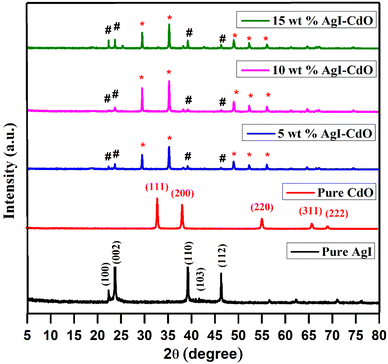 |
| | Fig. 1 XRD patterns of bare AgI, CdO, and different wt% AgI–CdO nanocomposite. | |
3.2. FTIR analysis
The distinct functional groups present in the synthesized materials were identified using infrared analysis. The IR spectra of AgI & CdO and composites of these two materials (AgI and CdO) with different weight percent of AgI, are displayed in Fig. S1.† The IR absorption spectrum of AgI showed a broad peak at 3446 & 1624 cm−1, corresponding to the vibrations of H2O.78,79 Whereas, the pure CdO showed an absorption peak at 430 cm−1 for Cd![[double bond, length as m-dash]](https://www.rsc.org/images/entities/char_e001.gif) O vibrational modes.69,80 On the other hand, all AgI–CdO nanocomposite samples displayed a significant shift with the appearance of a sharp and broad signal at 3600 & 1443 cm−1 for O–H. In addition, a small peak at 430 cm−1 for CdO is shown as a sharp and strong peak in all composite materials.
O vibrational modes.69,80 On the other hand, all AgI–CdO nanocomposite samples displayed a significant shift with the appearance of a sharp and broad signal at 3600 & 1443 cm−1 for O–H. In addition, a small peak at 430 cm−1 for CdO is shown as a sharp and strong peak in all composite materials.
3.3. Optical studies
This study was made to investigate optical response in the region 200–800 nm. The DRS spectra of pure AgI and CdO, as well as composite samples with various AgI weight percents, are displayed in Fig. 2a. The bare samples of CdO and AgI showed an absorption edge around 605 and 445 nm, respectively.49,51,81 The incorporation of AgI onto CdO with the increase in wt% from 5 to 15 led to 6 nm leading to a shift toward a higher wavelength from 447 to 453 nm. The bandgap of different samples was calculated using the Kubelka–Munk eqn (1).52,82–84
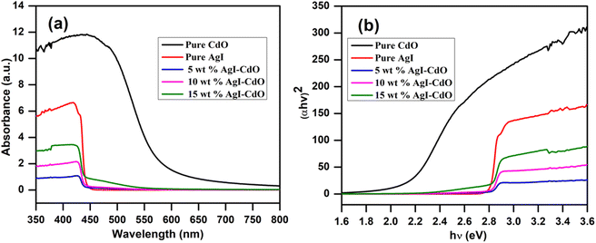 |
| | Fig. 2 (a) UV-vis DRS spectra of pure CdO, AgI, and different wt% of AgI doped CdO; and (b) Tauc's plot of synthesis photocatalyst. | |
α & h denotes the absorption coefficient and the Planck constant, respectively, ν refers to the light frequency.85 The “n” for direct and indirect transitions are 1 and 4, respectively.51,86 The bandgap (Eg) of pure (CdO and AgI) and nanocomposite (AgI–CdO) was calculated using the plot of (αhν)2 vs. hν, which is shown in Fig. 2b. The calculated bandgap energies for CdO, & AgI were 2 eV, & 2.75 eV. In contrast, all synthesized nanocomposite materials showed values between 2.68 and 2.74 eV.
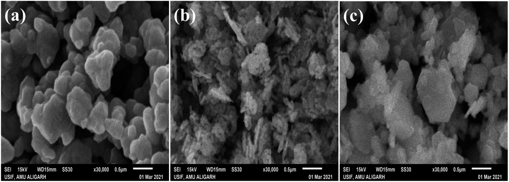
3.4. SEM study
This study was utilized to analyze the surface structure of all synthesized photocatalysts at higher magnification (0.5 μm), and images of pure (AgI and CdO) and nanocomposite (10 wt% AgI–CdO) are displayed in Fig. 3. The hexagonal and spherical-shaped as-synthesized pure AgI nanoparticles are seen in Fig. 3a.87,88 The bare CdO nanoparticle, on the other hand, has an oval-shaped morphology as observed in Fig. 3b.89 The spherical shape of AgI nanoparticles is distributed over the surface of CdO, as evidenced in SEM images (Fig. 3c) of the composite material (10 wt% AgI–CdO).
 |
| | Fig. 3 SEM images of as-prepared pure nanoparticles AgI (a), CdO (b), and heterostructure nanocomposite 10 wt% AgI–CdO (c), at higher magnification. | |
3.5. EDX and elemental mapping analysis
The results of this study are presented in Fig. 4. Fig. 4a shows two peaks are related to Cd, and O. The presence of Ag and I peaks assigned to the bare AgI nanoparticle is confirmed in Fig. 4b. Fig. 4c shows the EDX analysis of nanocomposite (10 wt% AgI–CdO), which shows all elements (Cd, O, Ag, and I), indicating that the synthesized sample comprises AgI and CdO. The weight percentages of each element present in CdO, AgI, and nanocomposite (10 wt% AgI–CdO) are shown in Fig. 4a–c. EDS elemental mapping results for the distribution of elements are presented in Fig. S2a–h.† The elements (Cd, O, Ag, and I) present on the surface of bare CdO (Fig. S2a and b†) and AgI (Fig. S2c and d†), are uniformly and non-uniformly distributions. Additionally, the elemental mapping of nanocomposite (Fig. S2e–h†) reveals a semi-uniform distribution of (Cd, O, Ag, and I) elements, showing that heterojunction nanocomposite has been effectively created.
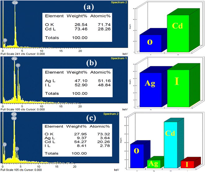 |
| | Fig. 4 EDX of as-synthesized photocatalyst, CdO (a), AgI (b), and 10 wt% AgI–CdO nanocomposite (c). | |
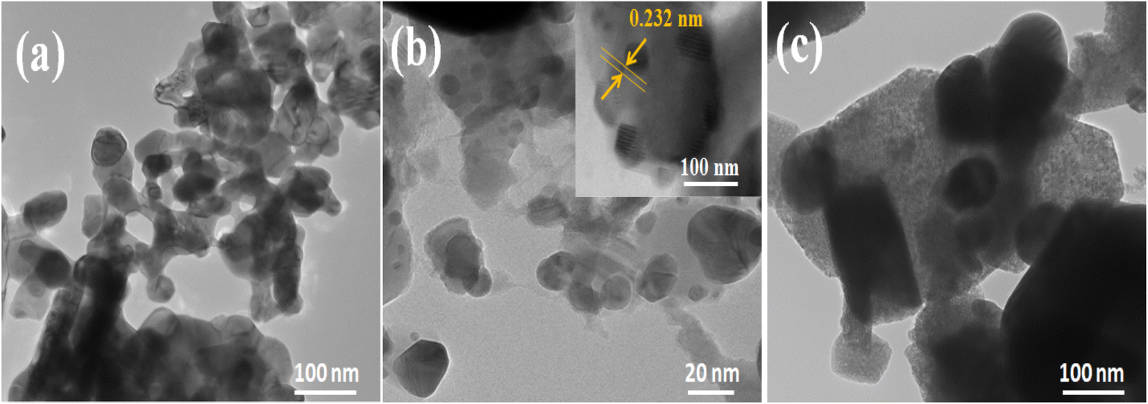
3.6. TEM analysis
TEM analysis was used to examine the internal morphology of CdO, AgI, and 10 wt% AgI–CdO nanocomposites and their results are displayed in Fig. 5. TEM images of CdO (Fig. 5a) are shown as nanospheres with closely attached cubes and hexagonal structures.90,91 Whereas, Fig. 5b shows TEM images of AgI nanoparticles in excellent spherical and hexagonal forms. The high-resolution image (insert in Fig. 5b) shows the identification of crystallography. The lattice spacing (0.23 nm) coincides with the (200) plane of AgI. The representative morphology of 10 wt% AgI–CdO heterojunction (Fig. 5c) depicts the dispersion of AgI particles on the surface lattice of CdO, suggesting that the AgI nanoparticles have grown directly on the CdO surface.
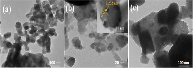 |
| | Fig. 5 TEM images of CdO (a), AgI (b), and 10 wt% AgI–CdO (c). | |
3.7. PL study
This study was made to assess the (e−/h+) pair recombination rate. Generally, slower charge carrier recombination is thought to imply a lower PL signal.82 Fig. 6 depicts the photoluminescence spectrum of all samples at 380 nm excitation in dimethyl sulfoxide from 400 to 650 nm. In comparison to both pure (CdO and AgI) and composite (5 and 15 wt% AgI–CdO), the photoluminescence response of 10 wt% AgI–CdO nanocomposite was found to be the lowest. This suggests that the combined and cooperative of CdO and AgI may reduce the recombination rate of the (e− and h+) pair, thereby increasing charged particles for photoreactions, confirming the increased photocatalytic activity of AgI–CdO nanocomposite materials.
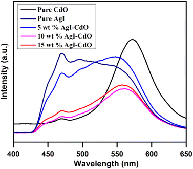 |
| | Fig. 6 PL emission spectra of pure CdO, AgI, and varying wt% AgI–CdO nanocomposite in DMSO at an excitation wavelength of 380 nm. | |
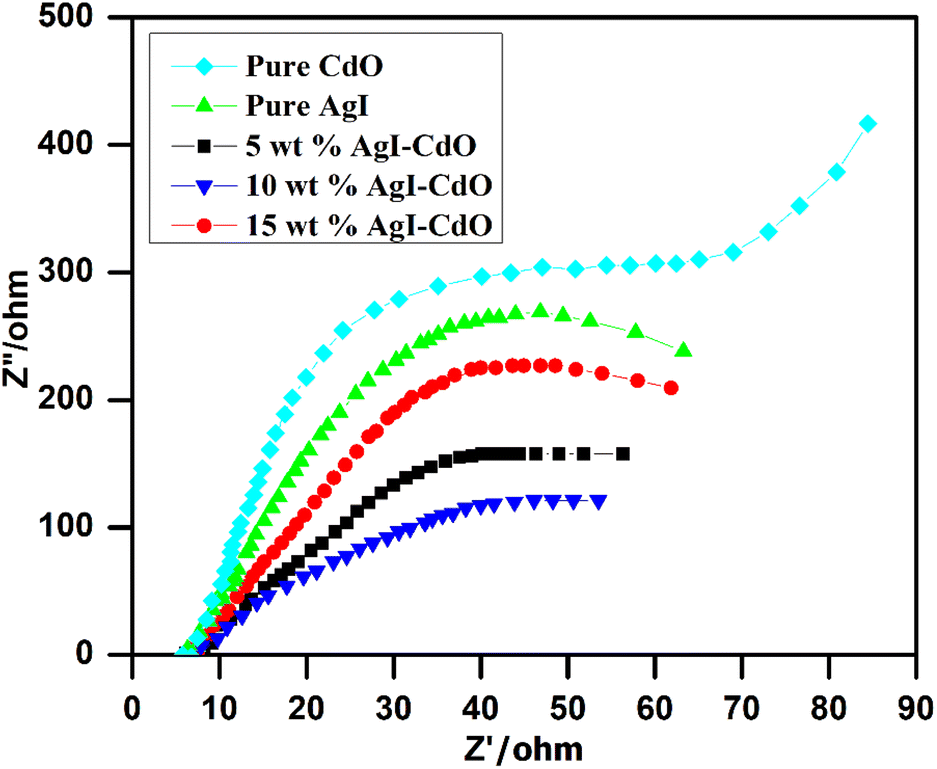
3.8. EIS analysis
The photogenerated charge separation is a critical factor in photocatalytic reactions. Electrochemical impedance spectroscopy (EIS) is a technique for determining the efficiency with which electron–hole pairs are separated. The charge-transfer resistance is inversely proportional to the semicircle diameter.79,83 The Nyquist impedance spectra of CdO, AgI, 5 wt% AgI–CdO, 10 wt% AgI–CdO, and 15 wt% AgI–CdO photocatalyst are shown in Fig. 7. The photocatalyst, 10 wt% AgI–CdO composite showed small semicircle among all samples, inferring the lowest charge transfer resistance. This demonstrates that the prepared AgI–CdO heterostructure has significantly improved electron/hole separation and charge transfer efficiency, which is beneficial in photocatalysis. This conclusion is consistent with the findings of the PL analyses.
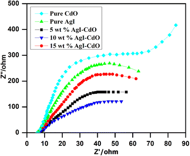 |
| | Fig. 7 Nyquist plots of all prepared pure and composite samples. | |
3.9. Photocatalytic degradation study
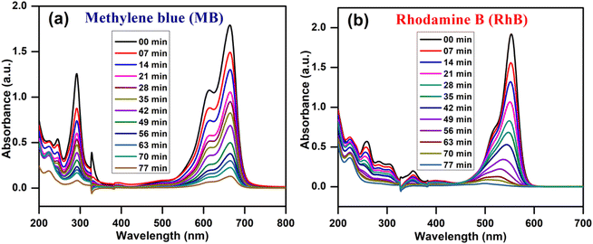
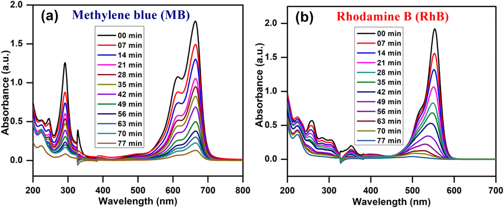
The photocatalytic efficiency of prepared nanoparticles was determined by illuminating desired compound (aqueous solution of RhB, MB, as well as paracetamol) under a visible light source in the presence of air bubbling. Before illumination, the photocatalyst and the desired compound (RhB, MB, and paracetamol) were kept in the dark for 30 min with constant stirring to get absorption–desorption equilibrium. Fig. 8a and b show the UV-vis spectrum of MB and RhB over 10 wt% AgI–CdO nanocomposite with respect to time, demonstrating 93–99% degradation in 77 min, respectively.
 |
| | Fig. 8 Decrease in absorbance on irradiation of MB (a) & RhB (b) over 10 wt% AgI–CdO at various times under light. | |
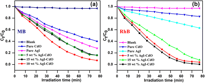
Fig. 9a and b show a decrease in concentration vs. irradiation time for MB and RhB with & without catalysts. Without a catalyst, the photodegradation of MB and RhB was insignificant implying that the compounds are quite stable and cannot be destroyed by direct photolysis. It's also worth noting that the 10 wt% AgI–CdO decomposes both dyes (RhB and MB) more quickly than any other produced catalyst. This may be due to the joint effect of AgI and CdO at this concentration, which may lead to sufficient light absorption & the separation of photogenerated charge carriers.
 |
| | Fig. 9 Photodegradation of MB (a) & RhB (b) with and without catalyst under light. | |
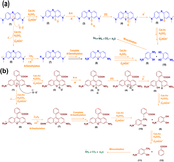
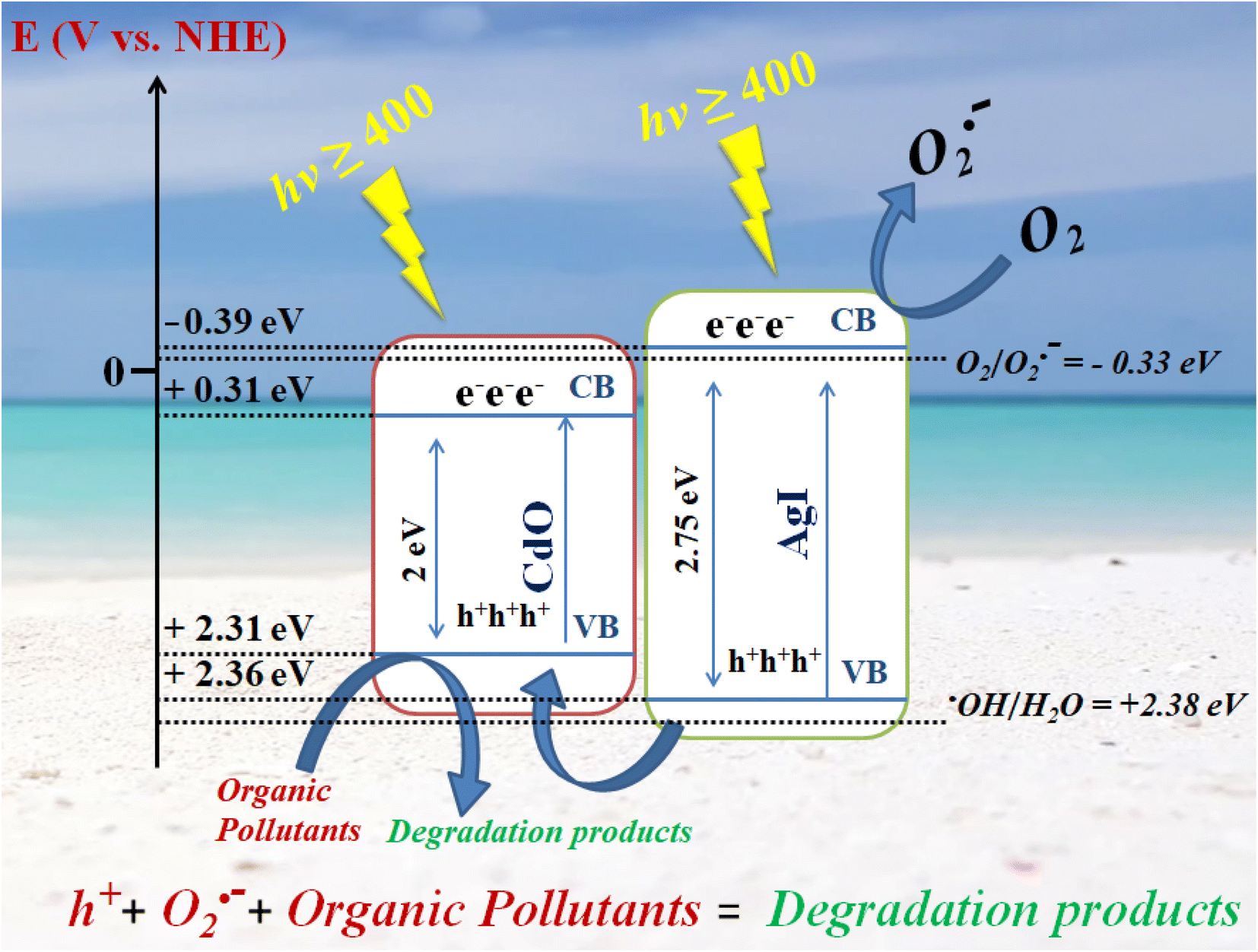
A mechanism for the decomposition of dyes in the presence of synthesized catalysts is given in Scheme 1a and b, showing the reaction of dyes with O2˙, HO˙, and h+ produced in the medium. As both dye derivatives have positive charges and are cationic dyes, the superoxide radical anion would be the most vulnerable kind of attack. As indicated in the following Scheme 1a and b, the dye derivatives undergo a further reaction with reactive species produced in the reaction media that ultimately mineralizes into non-toxic components after dealkylation and fragmentation.
 |
| | Scheme 1 (a and b) Possible mechanistic route for the breakdown of dyes. | |
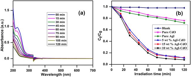
Additionally, the efficacy of the photocatalyst, 10 wt% AgI–CdO was assessed by studying the decomposition of a colorless organic compound such as a drug derivative (paracetamol) in aquatic suspension. Fig. 10a shows the paracetamol absorption spectra with time at its λmax (243 nm) during the decomposition process with 10 wt% AgI–CdO heterojunction nanocomposite, which shows a decrease in absorbance with irradiation time, showing 91.3% removal in 120 min. Fig. 10b displays the change in concentration of paracetamol vs. illumination time in the presence and absence of various photocatalysts. It's also worth noting that the paracetamol is degraded faster with the catalyst, 10 wt% AgI–CdO, compared with other prepared pure and composite materials. The excellent effect of the 10 wt% AgI–CdO nanocomposite for paracetamol elimination could be attributed to the efficient separation of charge carriers in heterojunction and good light absorption.
 |
| | Fig. 10 (a) Decrease in absorbance of paracetamol at different time with visible light over 10 wt% AgI–CdO heterojunction nanocomposite, and (b) concentration change vs. time in the absence and presence of different photocatalysts. | |
HPLC analysis was utilized to analyze the generated intermediates in the photodegradation of paracetamol over 10 wt% AgI–CdO. The HPLC peak of starting compound (Rt = 3.09 and 4.01 min) significantly decreases with time, and the paracetamol was removed within 120 min, as displayed in Fig. S3.† Besides, no by-products are found as detected in the time-dependent HPLC analysis of paracetamol under analogous conditions.
3.10. Photocatalytic degradation of RhB and MB under sunlight
The photocatalytic proficiency of synthesized AgI–CdO was also performed under sunlight (light intensity of 116 μW cm−2) under identical conditions using the same reaction vessel. Under this experiment, an aqueous solution of RhB or MB was taken in an immersion well photochemical reactor in the presence of a catalyst. The solution was illuminated under sunlight with proper cooling and stirring. The samples were taken at various time intervals, and spectrophotometric were monitored for degradation. A control experiment was carried out under identical conditions without a catalyst. The absorbance change at a different time on the illumination of RhB and MB under sunlight in the presence and absence of a catalyst is displayed in Fig. S4a–d.† The figure showed no appreciated change in the absence of a catalyst, whereas 85% and 94.3% degradation of MB and RhB could be seen in 180 and 210 min, respectively. The results suggest that the produced material is efficient in eliminating dyes under sunlight, which is quite promising from an application point of view.
3.11. Comparative degradation with another oxidative process (photo-Fenton and Degussa P25 TiO2)
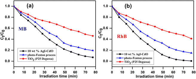
The activity of the synthesized photocatalyst (10 wt% AgI–CdO) was compared with the photo-Fenton process and commercially available Degussa P25 TiO2, by studying the removal of RhB and MB under similar conditions. Fig. 11 displays the concentration change vs. time on the illumination of MB and RhB with Degussa P25, Fenton's reagent, and the synthesized catalyst (10 wt% AgI–CdO) with visible light. The figure indicates better performance of the prepared catalyst for the decomposition of both dyes, exhibiting 93% and 99.5% degradation for MB and RhB in 77 min. In contrast, only 41–54% and 80.4–84% degradation was observed in the presence of P25 and Photoenton reagent, respectively.
 |
| | Fig. 11 Time-dependent variation in the concentrations of MB (a) & RhB (b) on illumination with visible light in the presence of Fenton's reagent, Degussa P25, and synthesized photocatalyst (10 wt% AgI–CdO) under analogous conditions. | |
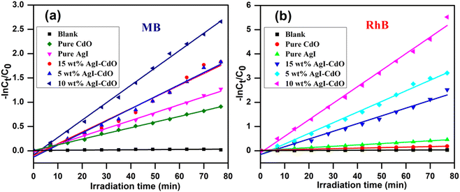
3.12. Degradation kinetics of RhB & MB
The degradation rate of MB and RhB was calculated using pseudo-first-order kinetics using the following eqn (2).
C0 and Ct are the starting and final dye concentrations at t = 0, and the final irradiation period; k is the first-order rate constant. Fig. 12a and b, respectively exhibit a plot of −ln(C0/Ct) vs. irradiation time displaying linear curve fit for eliminating MB and RhB utilizing pure AgI, CdO, and AgI–CdO heterojunction of nanocomposites with varied wt% of AgI. These figures were used to calculate the rate constant (kapp value) and correlation coefficients (R2) for dye degradation with and without catalysts. The results are summarized in Table 1. The kapp value for 10 wt% AgI–CdO nanocomposite was higher than all other synthesized photocatalysts. The results suggest that as the loading of AgI onto CdO increases from 5 to 10 wt%, the removal of MB and RhB increases, and a further increase in the amount of AgI loading resulted in a reduced photocatalytic response. This may be due to as the AgI loading increases, the charge carrier separation may be suppressed. Accordingly, from all the synthesized photocatalysts, 10 wt% AgI–CdO nanocomposite is found to be the most active catalyst for MB & RhB removal.
 |
| | Fig. 12 The pseudo-first-order cure fit shows the plot of −ln![[thin space (1/6-em)]](https://www.rsc.org/images/entities/char_2009.gif) Ct/C0 vs. irradiation time for the elimination of MB (a) & RhB (b) with various catalysts under a visible light source. Ct/C0 vs. irradiation time for the elimination of MB (a) & RhB (b) with various catalysts under a visible light source. | |
Table 1 Pseudo-first-order rate constants of all the synthesized photocatalysts and their corresponding R2 values for the elimination of MB and RhB
| Sample |
Apparent rate constant (kapp) (min−1) |
R2 |
| MB |
RhB |
MB |
RhB |
| Blank |
3.306 × 10⁻⁴ |
3.696 × 10⁻⁴ |
0.6193 |
0.8026 |
| CdO |
0.0117 |
0.0020 |
0.9979 |
0.9705 |
| AgI |
0.0160 |
0.0050 |
0.9956 |
0.9957 |
| 5 wt% AgI–CdO |
0.0240 |
0.0400 |
0.9719 |
0.992 |
| 15 wt% AgI–CdO |
0.0240 |
0.0310 |
0.9846 |
0.9819 |
| 10 wt% AgI–CdO |
0.0357 |
0.0680 |
0.9968 |
0.9936 |
3.13. Reusability and stability
From the standpoint of application, photocatalyst reusability is crucial in determining the catalyst's stability. As a result, the recycling process was investigated using recovered catalysts from the irradiated mixture of RhB under comparable conditions to assess the stability of the most active material (10 wt% AgI–CdO). The catalyst was collected and rinsed several times with ethanol and then with water to eliminate undesirable components and dried at 100 °C overnight before applying for the next cycle. Fig. 13a shows the % dye degradation after four consecutive cycles showing no change in catalyst photocatalytic activity. Additionally, there were no differences in the crystal structure of the catalyst (10 wt% AgI–CdO) according to XRD studied before and after the photocatalytic experiment. According to the results, the synthesized nanocomposite (10 wt% AgI–CdO) has high stability for eliminating organic contaminants from water and may be employed after numerous photocycle under visible light.
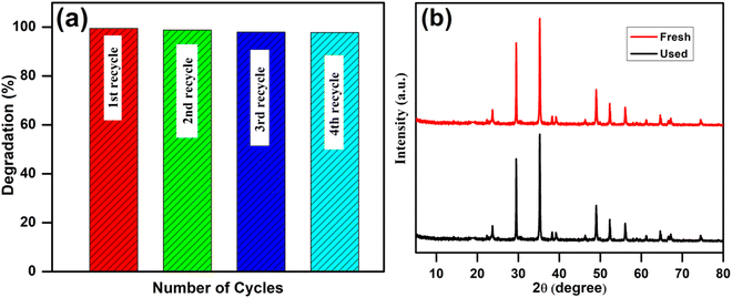 |
| | Fig. 13 (a) Recyclability of a 10 wt% AgI–CdO photocatalyst for the removal of RhB after four cycles, and (b) XRD of 10 wt% AgI–CdO before and after the photolysis experiment. | |
3.14. Antibacterial activity
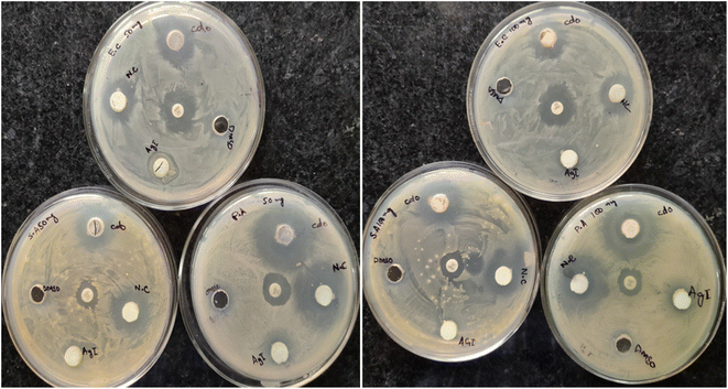
The agar method was used to examine the anti-bacterial activities of the prepared nanoparticles against Gram-positive bacteria (S. aureus) and Gram-negative bacteria (E. coli ATCC 25922 and P. aeruginosa ATCC PA01). Ampicillin and DMSO were utilized as the positive and negative control, respectively. Based on the antimicrobial assay performed to assess the antagonistic activity of CdO, AgI, and AgI–CdO nanocomposite against bacterial, it was noted that AgI–CdO exhibited a promising antagonistic influence at the concentration of 100 mg l−1 against (S. aureus) (E. coli ATCC 25922) and (P. aeruginosa ATCC PA01). Moreover, it was observed that AgI–CdO shows closely equivalent bactericidal potential as compared to the pure CdO NPs Table 2. In addition, AgI–CdO nanocomposite has shown admirable antibacterial activity against Gram-positive and Gram-negative pathogenic strains compared with pure AgI and standard drug ampicillin Table 2. Among the three different catalysts, bactericidal activity varied in the order of AgI–CdO > CdO > AgI, which might be due to the high surface area and light response and the interactions between AgI and CdO nanoparticles and the generation of ROS. An inhibition zone measurement was performed to test the activity of synthesized catalysts. Fig. 14 shows that no inhibition zone was formed around the AgI and DMSO. While, the AgI–CdO displayed the highest inhibition zone as compared to bare samples, with a diameter around 21 mm, 22 mm, and 29 mm against (S. aureus) (E. coli ATCC 25922) and (P. aeruginosa ATCC PA01) respectively, indicating that AgI–CdO visibly restrained the proliferation of bacteria. The results suggested that AgI–CdO played an important role in killing bacteria and that our synthesized nanocomposite could be used as an anti-bacterial agent.
Table 2 Tabulation displaying the inhibitory effect of CdO, AgI, and nanocomposites on P. aeroginosa, S. aureus, and E. coli
| Sample |
Zone of inhibition (mm) at different concentrations against three pathogenic strains |
| Concentration (100 mg mL−1) |
Concentration (50 mg mL−1) |
| P. aeruginosa |
S. aureus |
E. coli |
P. aeruginosa |
S. aureus |
E. coli |
| CdO |
28 |
19 |
20 |
27 |
19 |
20 |
| AgI |
14 |
NIL |
NIL |
12 |
NIL |
NIL |
| AgI–CdO |
29 |
21 |
22 |
29 |
20 |
20 |
| Ampicillin |
14 |
13 |
20 |
16 |
13 |
19 |
 |
| | Fig. 14 Zone inhibition image of P. aeroginosa, S. aureus, and E. coli. in the presence of CdO, AgI, and nanocomposites at different two concentrations of 50 and 100 mg l−1. | |
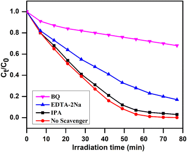
3.15. Quenching experiments
The scavengers such as BQ, EDTA-2Na, and IPA were used in the photodegradation reaction of the dye under analogous conditions to trap the primary active species [O2˙−, h+, and ˙OH] involved for the removal of compounds under investigation. Fig. 15 shows the percent degradation of RhB on irradiation an aqueous solution under visible light with 10 wt% AgI–CdO using the above mentioned quenchers under comparable conditions. The scavenger BQ significantly reduces RhB degradation, whereas EDTA-2Na showed a minor influence. Moreover, the addition of IPA did not affect the degradation of RhB, indicating −˙O2 & h+ are the key reactive species involved in the reaction.
 |
| | Fig. 15 Concentration change vs. time on irradiation of rhodamine B in an aqueous medium over 10 wt% AgI–CdO nanocomposite with and without quenchers. | |
In addition, the terephthalic acid (TA) fluorescence probe method was used to monitor hydroxyl radical-derived products formed in the photoreaction in a basic medium with a catalyst. The 2-hydroxyterephthalic acid (TA-OH) is thought to be produced when the hydroxyl radicals (˙OH) react with terephthalic acid and show a strong fluorescence peak (PL signal) at 425 nm, which was monitored at different time intervals.49,51 The commercially available TiO2 (Degussa, P25) was used as a standard catalyst to monitor this reaction under similar conditions. Fig. 16 shows the photoluminescence spectral change observed on irradiating an alkaline terephthalic acid solution (at excitation 315 nm) with Degussa P25 (Fig. 16a) and a 10 wt% AgI–CdO nanocomposite (Fig. 16b). Fig. 16a shows that the photoluminescence signal gradually increases with irradiation time over Degussa P25, indicating that hydroxyl radicals are involved in the reaction to form TA-OH. However, the photoluminescence signal was not found to increase in the presence of 10 wt% AgI–CdO nanocomposite (Fig. 15b), indicating that no ˙OH was produced under this condition. This concluded that the trapping experiment results are in agreement with these results.
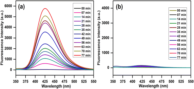 |
| | Fig. 16 PL spectrum observed on irradiation of a 5 × 10⁻⁴ M alkaline TA solution (at λexc 315 nm) with (a) TiO2 and (b) 10 wt% AgI–CdO nanocomposite photocatalyst. | |
3.16. Degradation mechanism
The band potential is an intrinsic feature of semiconducting materials that dictates the mechanism of these reactions. To elucidate the mechanism of (e−/h+) pairs generated on excitation of 10 wt% AgI–CdO nanocomposites, CB &VB potentials of produced pure materials (AgI and CdO) were computed using eqn (3) and (4).79
Ee = free-electron energy, X = electronegativity on the hydrogen scale (ca. 4.5 eV).
The mean of the 1st ionization energy (eV) and the electron affinity was used to calculate the absolute electronegativity (eV). The terms EVB, ECB, and Eg refer to the semiconductor's, VB & CB potential and bandgap energy, respectively.
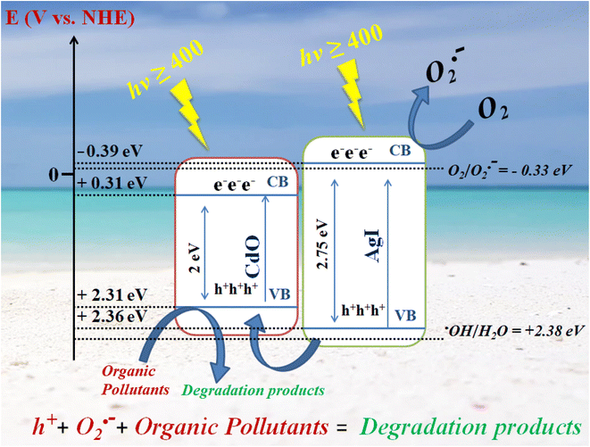
CdO's VB and CB energies were found to be +2.31 eV and 0.31 eV, while AgI's are +2.36 eV & −0.39 eV. The bandgap energies of CdO & AgI have been calculated to be 2 eV and 2.75 eV. A plausible photocatalytic mechanism for the breakdown of compounds under investigation catalyzed by AgI–CdO is postulated in Scheme 2 based on the previous results. The electrons in VB of CdO and AgI can easily be excited to their CB when exposed to visible light, resulting in the creation of holes in their VBs (eqn (5) and (6)). Furthermore, AgI's CB energy level (−0.39) is more negative than the potential of O2/O2˙− (−0.33 eV),51 the electrons in the CB of AgI can be trapped by dissolved molecular oxygen to generate O2˙− (eqn (7)) leading to improved photocatalytic efficiency (eqn (8)). The VB of AgI (+2.36 eV) is greater than that of CdO (+2.31 eV), thus holes generated can be transported into CdO's VB (eqn (9)) and react directly with organic compounds, resulting in the complete of degradation (eqn (10)).
 |
| | Scheme 2 A proposed mechanism for decomposition of organic pollutants by AgI–CdO photocatalyst under sun/visible light irradiation. | |
The transformation of ˙OH from H2O has a potential of +2.38,49,51 higher than CdO and AgI's VB potentials. As a result, the photoinduced h+ in the VB of CdO & AgI cannot oxidize the water molecule to give ˙OH, which is in agreement with the PL results that ˙OH is not observed using AgI–CdO as a catalyst when exposed to light. This is in line with the results of the trapping experiment.
The photogenerated carriers can be successfully segregated in this route, resulting in significantly increased photocatalytic activity. These findings are consistent with PL and UV-vis data, and increased photocatalytic activity is attributable to increased light-harvesting capacity and the ability to produce and move excited charge carriers.
The sequential representation of the generation of reactive species on irradiated semiconductors in aqueous suspension and its further reaction with organic pollutants is represented below;
| | |
AgI + hν → h+(AgI) + e−(AgI)
| (5) |
| | |
CdO + hν → h+(CdO) + e−(CdO)
| (6) |
| | |
Organic pollutants + O2˙− → degradation product
| (8) |
| | |
h+(AgI) + (CdO) → h+(CdO)
| (9) |
| | |
Organic pollutants + h+ → degradation product
| (10) |
4. Conclusions
In conclusion, AgI–CdO nanocomposites were successfully produced at room temperature using a simple deposition cum precipitation process and employed for the photodegradation of MB, RhB, and paracetamol. The nanocomposite materials performed better activity compared to bare CdO and AgI. The performance of the most active catalyst (10 wt% AgI–CdO) was compared with Degussa P25, Fenton's reagent, and also under sunlight for dye degradation under the same conditions. According to the scavenger studies and the TA-OH probe experiment, hydroxyl radicals (˙OH) play a minor role, whereas superoxide radicals  is the main reactive species in the photooxidation process. The heterojunction nanocomposites formed between CdO and AgI can collectively minimize the e− and h+ pair recombination rate, resulting in a greatly improved separation efficiency, which is responsible for high photodegradation activity. In vitro antibacterial studies revealed that the AgI–CdO showed the highest antibacterial efficacy against (S. aureus) (E. coli ATCC 25922) and (P. aeruginosa ATCC PA01) with zone inhibition 21 mm, 22 mm, and 29 mm respectively compared with standard drug and pure AgI. This could be due to the interactions between AgI and CdO nanoparticles and the generation of ROS. The present study demonstrates a straightforward, effective, and simple approach to synthesizing highly efficient visible-light active catalysts for the removal of pollutants in water systems and the photodynamic treatment of pathogenic bacterial strains. Moreover, this approach also offers a number of advantages, such as the use of solar light, less reaction time, small catalyst concentration, high degradation efficiency, air as the oxidant, as an anti-bacterial agent, and ease of catalyst recycling.
Conflicts of interest
There are no conflicts to declare.
Acknowledgements
The authors are thankful to the SERB Project (CRG/2019/001370), DST, and UGC for DRS II, PURSE & FIST for their support to the chemistry department at AMU, Aligarh. The authors would like to acknowledge the Deanship of Scientific Research at Umm Al-Qura University, for supporting this work by Grant code: 22UQU4320545DSR30. Murad Z. A. Warshagha expresses gratitude to ICCR for providing financial support for his PhD program.
References
- N. Sharotri, D. Sharma and D. Sud, J. Mater. Res. Technol., 2019, 8, 3995–4009 CrossRef CAS.
- A. Shet and S. K. Vidya, Sol. Energy, 2016, 127, 67–78 CrossRef CAS.
- D. Yu, J. Bai, H. Liang and C. Li, J. Alloys Compd., 2016, 683, 329–338 CrossRef CAS.
- D. Yu, J. Bai, H. Liang, J. Wang and C. Li, RSC Adv., 2015, 5, 91457–91465 RSC.
- O. O. Alameer, A. Timoumi, N. El Guesmi, S. N. Alamri, W. Belhadj, K. Althagafi and S. A. Ahmed, Eur. Phys. J. Plus, 2022, 137, 1160 CrossRef CAS.
- M. M. Kaid, A. S. Khder, S. A. Ahmed, A. A. Ibrahim, H. M. Altass, R. I. Alsantali, R. S. Jassas, M. A. Khder, M. M. Al-Rooqi, Z. Moussa and A. I. Ahmed, ACS Omega, 2022, 7, 17223–17233 CrossRef CAS PubMed.
- C. Nefzi, B. Askri, B. Yahmadi, N. El Guesmi, J. M. García, N. Kamoun-Turki and S. A. Ahmed, J. Photochem. Photobiol. A: Chem., 2022, 431, 114041 CrossRef CAS.
- C. Nefzi, B. Yahmadi, N. El Guesmi, J. M. García, N. Kamoun-Turki and S. A. Ahmed, J. Mol. Struct., 2022, 1251, 131943 CrossRef CAS.
- A. Pramothkumar, N. Senthilkumar, K. C. M. G. Malar, M. Meena and I. V. Potheher, J. Mater. Sci.: Mater. Electron., 2019, 30, 19043–19059 CrossRef CAS.
- J. Di, J. X. Xia, M. Ji, B. Wang, S. Yin, Q. Zhang, Z. Chen and H. Li, Appl. Catal., B, 2016, 183, 254–262 CrossRef CAS.
- J. Xia, J. Di, H. Li, H. Xu, H. Li and S. Guo, Appl. Catal., B, 2016, 181, 260–269 CrossRef CAS.
- J. Jin, Q. Liang, C. Ding, Z. Li and S. Xu, J. Alloys Compd., 2017, 691, 763–771 CrossRef CAS.
- F. Zhang, Q. Wen, M. Hong, Z. Zhuang and Y. Yu, Chem. Eng. J., 2017, 307, 593–603 CrossRef CAS.
- Y. Tang, H. Zhou, K. Zhang, J. Ding, T. Fan and D. Zhang, Chem. Eng. J., 2015, 262, 260–267 CrossRef CAS.
- T. Zhu, Y. Song, H. Ji, Y. Xu, Y. Song, J. Xia, S. Yin, Y. Li, H. Xu, Q. Zhang and H. Li, Chem. Eng. J., 2015, 271, 96–105 CrossRef CAS.
- D. Liu, J. Wang, X. Bai, R. Zong and Y. Zhu, Adv. Mater., 2016, 28, 7284–7290 CrossRef CAS PubMed.
- J. Maruthai, A. Muthukumarasamy and B. Baskaran, IET Nanobiotechnol., 2019, 13(2), 134–143 CrossRef PubMed.
- H. A. Abubshait, M. Saad, S. Iqbal, S. A. Abubshait, A. Bahadur, M. Raheel, F. H. Alshammari, N. Alwadai, H. Alrbyawi, M. A. S. Abourehab, E. B. Elkaeed, M. A. Qayyum and H. H. Somaily, J. Mol. Struct., 2023, 1271, 134100 CrossRef CAS.
- T. M. Bawazeer, Catalyst, 2022, 12, 1093 CrossRef CAS.
- S. A. Ahmed and Z. S. Seddigi, US Pat., US9700882B2, 2017.
- Z. S. Seddigi, S. A. Ahmed, A. M. Nassif and M. M. Al-Thbaiti, US Pat., US9944540B2, 2018.
- M. Arellano-Cortaza, E. Ramírez-Morales, U. Pal, G. Pérez-Hernández and L. Rojas-Blanco, Ceram. Int., 2021, 47, 27469–27478 CrossRef CAS.
- Z. Wei, F. Liang, Y. Liu, W. Luo, J. Wang, W. Yao and Y. Zhu, Appl. Catal., B, 2017, 201, 600–606 CrossRef CAS.
- J. Zhou, M. Zhang and Y. Zhu, Phys. Chem. Chem. Phys., 2014, 16, 17627–17633 RSC.
- N. Huang, J. Shu, Z. Wang, M. Chen, C. Ren and W. Zhang, J. Alloys Compd., 2015, 648, 919–929 CrossRef CAS.
- S. G. Kumar and K. S. R. K. Rao, RSC Adv., 2015, 5, 3306–3351 RSC.
- V. Vaiano, O. Sacco, D. Sannino and P. Ciambelli, Chem. Eng. J., 2015, 261, 3–8 CrossRef CAS.
- A. A. Ibrahim, R. S. Salama, S. A. El-Hakam, A. S. Khder and A. I. Ahmed, Colloids Surf., A, 2021, 631, 127753 CrossRef CAS.
- M. Morad, M. A. Karim, H. M. Altass and A. S. Khder, Environ. Technol., 2021, 42, 2680–2689 CrossRef CAS PubMed.
- E. U. Mughal, A. Javaid, M. Imran, M. A. S. Abourehab, E. B. Elkaeed, N. Naeem, A. Y. A. Alzahrani, A. Sadiq and S. F. Kainat, Inorganica Chim. Acta, 2023, 546, 121329 CrossRef CAS.
- Y. Wang, Q. Wang, X. Zhan, F. Wang, M. Safdar and J. He, Nanoscale, 2013, 5, 8326–8339 RSC.
- H. Liu, H. Hou, F. Gao, X. Yao and W. Yang, ACS Appl. Mater. Interfaces, 2016, 8(3), 1929–1936 CrossRef CAS PubMed.
- Y. Chen, W. Huang, D. He, Y. Situ and H. Huang, ACS Appl. Mater. Interfaces, 2014, 6(16), 14405–14414 CrossRef CAS PubMed.
- L. Yang, Z. Si, D. Weng and Y. Yao, Appl. Surf. Sci., 2014, 313, 470–478 CrossRef CAS.
- D. Chen, K. Wang, T. Ren, H. Ding and Y. Zhu, Dalton Trans., 2014, 43, 13105–13114 RSC.
- Z. Liu, X. Liu, D. Lu, P. Fang and S. Wang, Mater. Lett., 2014, 130, 143–145 CrossRef CAS.
- W. Gao, M. Wang, C. Ran and L. Li, Chem. Commun., 2015, 51, 1709–1712 RSC.
- Y. Li, B. Wang, S. Liu, X. Duan and Z. Hu, Appl. Surf. Sci., 2015, 324, 736–744 CrossRef CAS.
- K. Kalpana and V. Selvaraj, Ceram. Int., 2015, 41, 9671–9679 CrossRef CAS.
- S. Pal, S. Maiti, U. N. Maiti and K. K. Chattopadhyay, CrystEngComm, 2015, 17, 1464–1476 RSC.
- Y. Xie, H. Zhang, J. Lv, J. Zhao, D. Jiang and Q. Zhan, Appl. Surf. Sci., 2022, 578, 152074 CrossRef CAS.
- Y. Peng, H. Zhou, Y. Wu, Z. Ma, R. Zhang, H. Tu and L. Jiang, J. Colloid Interface Sci., 2022, 609, 188–199 CrossRef CAS PubMed.
- C. An, W. Jiang, J. Wang, S. Wang, Z. Ma and Y. Li, Dalton Trans., 2013, 42, 8796–8801 RSC.
- J. Wang, P. Wang, Y. Cao, J. Chen, W. Li, Y. Shao, Y. Zheng and D. Li, Appl. Catal., B, 2013, 136–137, 94–102 CrossRef CAS.
- C. Wu, Mater. Lett., 2014, 136, 262–264 CrossRef CAS.
- S. Khanchandani, P. K. Srivastava, S. Kumar, S. Ghosh and A. K. Ganguli, Inorg. Chem., 2014, 53(17), 8902–8912 CrossRef CAS PubMed.
- C. Dong, K.-L. Wu, M.-R. Li, L. Liu and X.-W. Wei, Catal. Commun., 2014, 46, 32–35 CrossRef CAS.
- M. Pirhashemi and A. Habibi-Yangjeh, J. Mater. Sci.: Mater. Electron., 2016, 27, 4098–4108 CrossRef CAS.
- H. Huang, N. Huang, Z. Wang, G. Xia, M. Chen, L. He, Z. Tong and C. Ren, J. Colloid Interface Sci., 2017, 502, 77–88 CrossRef CAS PubMed.
- M. H. T. Tung, N. T. D. Cam, D. V. Thuan, P. V. Quan, C. V. Hoang, T. T. T. Phuong, N. T. Lam, T. T. Tam, N. T. P. L. Chi, N. T. Lan, D. N. Thoąi and T.-D. Pham, Ceram. Int., 2020, 46, 6012–6021 CrossRef.
- Y. Cheng, L. He, G. Xia, C. Ren and Z. Wang, New J. Chem., 2019, 43, 14841–14852 RSC.
- Y. Pan, X. Yuan, L. Jiang, H. Wang, H. Yu and J. Zhang, Chem. Eng. J., 2020, 384, 123310 CrossRef CAS.
- M. Tang, Y. Ao, C. Wang and P. Wang, Appl. Catal., B, 2020, 268, 118395 CrossRef CAS.
- D. A. Reddy, J. Choi, S. Lee, R. Ma and T. K. Kim, RSC Adv., 2015, 5, 67394–67404 RSC.
- S. K. Lakhera, R. Venkataramana, G. Mathew, H. Y. Hafeez and B. Neppolian, Mater. Sci. Semicond. Process., 2020, 106, 104756 CrossRef CAS.
- N. Güy and M. Özacar, J. Photochem. Photobiol. A: Chem., 2019, 370, 1–11 CrossRef.
- J. Choi, D. A. Reddy and T. K. Kim, Ceram. Int., 2015, 41, 13793–13803 CrossRef CAS.
- S. K. Lakhera, H. Y. Hafeez, R. Venkataramana, P. Veluswamy, H. Choi and B. Neppolian, Appl. Surf. Sci., 2019, 487, 1289–1300 CrossRef CAS.
- X.-G. Zhang, D.-L. Guan, C.-G. Niu, Z. Cao, C. Liang, N. Tang, L. Zhang, X.-J. Wen and G.-M. Zeng, Sci. Total Environ., 2019, 668, 730–742 CrossRef CAS PubMed.
- J. Yi, L. Huang, H. Wang, H. Yu and F. Peng, J. Hazard. Mater., 2015, 284, 207–214 CrossRef CAS PubMed.
- J. Chen, W. Mei, Q. Huang, N. Chen, C. Lu, H. Zhu, J. Chen and W. Hou, J. Alloys Compd., 2016, 688, 225–234 CrossRef CAS.
- X. Zhang, P. Yang, Y. Bai, B. Yang and W. Liu, Adv. Powder Technol., 2020, 31, 973–985 CrossRef CAS.
- L. Wang, H. Hong, C. Zhang, L. Sun, S. Liu and S. Wang, J. Environ. Sci., 2016, 41, 112–120 CrossRef CAS PubMed.
- C. M. Magdalane, K. Kaviyarasu, J. J. Vijaya, B. Siddhardha and B. Jeyaraj, J. Photochem. Photobiol., B, 2016, 163, 77–86 CrossRef CAS PubMed.
- R. Yang, G. Song, L. Wang, Z. Yang, J. Zhang, X. Zhang, S. Wang, L. Ding, N. Ren, A. Wang and X. Yu, Small, 2021, 17, 2102744 CrossRef CAS PubMed.
- L. Wang, X. Tang, Z. Yang, J. Guo, Z. You, Y. Cai, X. Niu, X. Zhang, L. Zhang, J. Zhang, A. Wang, J. Liu, H. Liu and X. Yu, Chem. Eng. J., 2023, 451, 139007 CrossRef CAS.
- L. Wang, X. Zhang, X. Yu, F. Gao, Z. Shen, X. Zhang, S. Ge, J. Liu, Z. Gu and C. Chen, Adv. Mater., 2019, 31, 1901965 CrossRef PubMed.
- J. Liu, J. Chen, Z. Wu, K. Zhu, J. Wang, Z. Li, G. Tai, X. Liu and S. Lu, J. Alloys Compd., 2021, 852, 156848 CrossRef CAS.
- S. Rajaboopathi and S. Thambidurai, Curr. Appl. Phys., 2017, 17, 1622–1638 CrossRef.
- K. Kaviyarasu, E. Manikandan, P. Paulraj, S. B. Mohamed and J. Kennedy, J. Alloys Compd., 2014, 593, 67–70 CrossRef CAS.
- J. Ahmad and K. Majid, New J. Chem., 2018, 42, 3246–3259 RSC.
- I. Ahemen and F. B. Dejene, J. Mater. Sci.: Mater. Electron., 2018, 29, 2140–2150 CrossRef CAS.
- P. P. Pal and J. Manam, Radiat. Phys. Chem., 2013, 88, 7–13 CrossRef CAS.
- V. Koutu, P. Ojhab, L. Shastri and M. M. Malik, AIP Conf. Proc., 2018, 1953, 030278 CrossRef.
- J. H. Zheng, J. L. Song, Q. Jiang and J. S. Lian, Appl. Surf. Sci., 2012, 258, 6735–6738 CrossRef CAS.
- V. Manthina and A. G. Agrios, Nano-Struct. Nano-Objects, 2016, 7, 1–11 CrossRef CAS.
- A. L. Al-Otaibi, E. Howsawi and T. Ghrib, Nano-Struct. Nano-Objects, 2020, 24, 100551 CrossRef CAS.
- S. Shaker-Agjekandy and A. Habibi-Yangjeh, Mater. Sci. Semicond. Process., 2015, 34, 74–81 CrossRef CAS.
- M. Z. A. Warshagha and M. Muneer, ACS Omega, 2022, 7(34), 30171–30183 CrossRef CAS PubMed.
- K. Sirohi, S. Kumar, V. Singh and A. Vohra, Acta Metall. Sin. (Engl. Lett.), 2018, 31, 254–262 CrossRef CAS.
- N. Pourshirband, A. Nezamzadeh-Ejhieh and S. N. Mirsattari, Chem. Phys. Lett., 2020, 761, 138090 CrossRef CAS.
- M. Z. A. Warshagha and M. Muneer, Langmuir, 2020, 36(33), 9719–9727 CrossRef CAS PubMed.
- M. Z. A. Warshagha and M. Muneer, Surf. Interfaces, 2021, 26, 101394 CrossRef CAS.
- M. Z. A. Warshagha and M. Muneer, Int. J. Environ. Anal. Chem., 2020, 102, 6339–6358 CrossRef.
- X. Yuan, L. Jiang, X. Chen, L. Leng, H. Wang, Z. Wu, T. Xiong, J. Liang and G. Zeng, Environ. Sci. Nano, 2017, 4, 2175–2185 RSC.
- F. Chen, Q. Yang, J. Sun, F. Yao, S. Wang, Y. Wang, X. Wang, X. Li, C. Niu, D. Wang and G. Zeng, ACS Appl. Mater. Interfaces, 2016, 8(48), 32887–32900 CrossRef CAS PubMed.
- H. I. Elsaeedy, Mater. Sci. Semicond. Process., 2019, 93, 360–365 CrossRef CAS.
- S. R. Sri Ramkumar, N. Sivakumar, G. Selvakumar, T. Selvankumar, C. Sudhakar, B. Ashokkumar and S. Karthi, RSC Adv., 2017, 7, 34548–34555 RSC.
- M. Poloju, N. Jayababu, E. V. Rao, R. G. Rao and M. V. R. Reddy, Surf. Interfaces, 2020, 20, 100586 CrossRef CAS.
- P. S. Kumar, M. Selvakumar, P. Bhagabati, B. Bharathi, S. Karuthapandian and S. Balakumar, RSC Adv., 2014, 4, 32977–32986 RSC.
- M. Z. A. Warshagha and M. Muneer, Environ. Nanotechnol. Monit. Manag., 2022, 18, 100728 CAS.
|
| This journal is © The Royal Society of Chemistry 2023 |
Click here to see how this site uses Cookies. View our privacy policy here. 
 Open Access Article
 This Open Access Article is licensed under a Creative Commons Attribution-Non Commercial 3.0 Unported Licence
 *a,
Ismail I. Althagafib and
Saleh A. Ahmed
*a,
Ismail I. Althagafib and
Saleh A. Ahmed


 is the main reactive species in the photooxidation process. The heterojunction nanocomposites formed between CdO and AgI can collectively minimize the e− and h+ pair recombination rate, resulting in a greatly improved separation efficiency, which is responsible for high photodegradation activity. In vitro antibacterial studies revealed that the AgI–CdO showed the highest antibacterial efficacy against (S. aureus) (E. coli ATCC 25922) and (P. aeruginosa ATCC PA01) with zone inhibition 21 mm, 22 mm, and 29 mm respectively compared with standard drug and pure AgI. This could be due to the interactions between AgI and CdO nanoparticles and the generation of ROS. The present study demonstrates a straightforward, effective, and simple approach to synthesizing highly efficient visible-light active catalysts for the removal of pollutants in water systems and the photodynamic treatment of pathogenic bacterial strains. Moreover, this approach also offers a number of advantages, such as the use of solar light, less reaction time, small catalyst concentration, high degradation efficiency, air as the oxidant, as an anti-bacterial agent, and ease of catalyst recycling.