
 Open Access Article
 This Open Access Article is licensed under a Creative Commons Attribution-Non Commercial 3.0 Unported Licence
Defect and strain engineered MoS2/graphene catalyst for an enhanced hydrogen evolution reaction†
Zhaoyuan Yanga,
Jia Zhu *a,
Xianglan Xub,
Lei Wanga,
Guobing Zhou*a,
Zhen Yang*a and
Yongfan Zhangc
*a,
Xianglan Xub,
Lei Wanga,
Guobing Zhou*a,
Zhen Yang*a and
Yongfan Zhangc
aKey Lab of Fluorine and Silicon for Energy Materials and Chemistry of Ministry of Education, College of Chemistry and Chemical Engineering, Jiangxi Normal University, Nanchang 330022, China. E-mail: jia_zhu@jxnu.edu.cn; gbzhou@jxnu.edu.cn; yangzhen@jxnu.edu.cn
bInstitute of Applied Chemistry, College of Chemistry, Nanchang University, Nanchang, Jiangxi 330031, China
cCollege of Chemistry, Fuzhou University, Fuzhou, Fujian 350108, China
First published on 27th January 2023
Abstract
Molybdenum disulfide (MoS2) has been demonstrated as a promising non-precious metal electrocatalyst for the hydrogen evolution reaction (HER). However the efficiency of the HER falls short of expectations due to the large inert basal plane and poor electrical conductivity. In order to activate the MoS2 basal plane and enhance the hydrogen evolution reaction (HER) activity, two strategies on the hybrid MoS2/graphene, including intrinsic defects and simultaneous strain engineering, have been systematically investigated based on density functional theory calculations. We firstly investigated the HER activity of a MoS2/graphene hybrid material with seven types of point defect sites, VS, VS2, VMo, VMoS3, VMoS6, MoS2 and S2Mo. Using the hydrogen adsorption free energy (ΔGH) as the descriptor, results demonstrate that four of these seven defects (VS, VS2, MoS2, VMoS3) act as a catalytic active site for the HER and exhibited superior electrocatalytic activity. More importantly, we found that ΔGH can be further tuned to an ideal value (0 eV) with proper tensile strain, which effectively optimizes and boosts the HER activity, especially for the VS, VS2, VMoS3 defects and MoS2 antisite defects. Our results demonstrated that a proper combination of tensile strain and defect structure is an effective approach to achieve more catalytic active sites and further tune and boost the intrinsic activity of the active sites for HER performance. Furthermore, the emendatory d-band center of metal proves to be an excellent descriptor for determining H adsorption strength on defective MoS2/graphene hybrid material under different strain conditions. In addition, the low kinetic barrier of H2 evolution indicated that the defective MoS2/graphene system exhibited favorable kinetic activity in both the Volmer–Heyrovsky and the Volmer–Tafel mechanism. These results may pave a new way to design novel ultrahigh-performance MoS2-based HER catalysts.
1. Introduction
The process of electrochemical water splitting to produce hydrogen energy via the hydrogen evolution reaction (HER) has been considered a renewable, green, and highly efficient technique. Pt and Pt-group metals are regarded as the best catalysts for the hydrogen evolution reaction (HER).1 However, these metals are a limited natural resource, which significantly elevates the cost of using these metals, thereby limiting their utilization in practice. These major issues make it essential to develop a naturally abundant and inexpensive material with highly active HER performance as an alternative to Pt, but has remained a challenge thus far.Recently, molybdenum disulfide (MoS2) has attracted a large amount of attention as a promising non-precious metal catalyst for the hydrogen evolution reaction (HER). MoS2 is low-cost, naturally abundant, has high chemical stability, and a comparable catalytic HER performance to Pt.2,3 However, MoS2 HER efficiency does not meet expectations because the catalytic activity of MoS2 highly depends on its active edge sites, thereby rendering the large inert basal plane non-catalytic, as well as a poor electrical conductivity for the catalyst.4 Many strategies are being explored to optimize the catalytic performances of MoS2, including controlling the size of MoS2 to expose more active edge sites using nanoparticles,5 nanowires,6 nanoflakes7 and nanotube,8 as well as coupling MoS2 with other conductive scaffolds, such as graphene,9,10 carbon nanotube11 and Au electrode,12 to improve electrical conductivity of MoS2 material and HER electrocatalytic activity. Chemical doping13 and defects formation14,15 are two additional methods used to improve the intrinsic active sites. Voiry et al. reported that the catalytic activity of the 2H-MoS2 basal plane was significantly enhanced when the presence of sulfur vacancies were combined with an efficient charge injection between the conductive Au support and the catalyst.12 Using argon plasma exposure, Tsai et al. have shown that S-vacancies on 2H-MoS2 exhibited higher intrinsic activity in HER than at the edge sites.15
Recent research has additionally found that tuning strain is a powerful strategy for tailoring the catalytic activity to achieve the highest intrinsic HER activity.16–18 The application of external strain on the 1T′-MX2 (M = Mo, W; X = S, Se, Te) significantly tunes and boosts the HER performance.19 Li et al. have reported that introducing strain on the S vacancy-MoS2 basal plane could enormously enhance its HER activity.20 Dimakis et al. have also examined the S, S2 vacancies and C vacancies in the MoS2/graphene heterostructure could be engineered for producing efficient HER electrocatalysts based on density functional theory (DFT), but the reaction model by combining the molecular dynamics (MD) simulations are not considered.21,22 Recently, experimentation has systematically identified a variety of intrinsic defects prepared by chemical vapor deposition (CVD) grown monolayer MoS2.23,24 However, it is still unknown what potential roles would various combinations of the different intrinsic defects and engineered strains play on the HER performance of MoS2-based materials. It prompted us to investigate if strain engineering and different intrinsic defects simultaneously could increase both the number of active sites and intrinsic catalysis activity, thus exhibiting significantly enhanced HER performance for MoS2-based hybrid materials.
In this study, we explored both the strain engineering and intrinsic defect strategies to optimize the hydrogen evolution reaction (HER) catalytic activity of the MoS2 basal plane grown on graphene using the first-principles DFT calculation. Used 7 different types of point defects commonly observed in experiments includes a monosulfur vacancy (VS), a disulfur vacancy (VS2), an Mo vacancy (VMo), a vacancy complex of Mo and three nearby sulfur (VMoS3), a vacancy complex of Mo and six nearby sulfur (VMoS6), antisite defects where an Mo atom substitutes for an S2 column (MoS2) and an S2 column substitutes for an Mo atom (S2Mo). Our results show that MoS2/graphene hybrid with intrinsic defects can activate the inert basal plane and greatly improve the HER activity. Furthermore, we found significant improvement of the HER intrinsic activity of the active site for the MoS2/graphene hybrid material when we use a combination of a defect structure and a proper strain. Our results may pave an effective strategy to design ultrahigh-performance MoS2-based HER catalysts.
2. Computational methods
2.1. Model systems
The optimized lattice parameters of monolayer MoS2 and graphene were calculated to be 3.17 Å and 2.46 Å, respectively, which is well in agreement with the experimental and theoretical results.25–27 The supercell structure of the composite system is (4 × 4) MoS2 and (5 × 5) graphene, which includes about a 2.9% lattice mismatch. The lattice of graphene was initially set to match that of monolayer MoS2 in the supercell, and then the supercells fully relaxed for both the lattice constants and the atomic geometry. Eventually, the mismatch would finally disappear, leading to the commensurate systems. The relaxed lattice constants of the MoS2/graphene system is approximately 12.44 Å. The lattice of parameter of MoS2 layer in the supercell are slightly compressed by 1.9% (from 3.17 Å to 3.11 Å) when compared to the corresponding isolated sheet, while the graphene layer in the supercells are slightly expanded by 1.2% (from 2.46 Å to 2.49 Å).The lattice constants experienced a slight decrease for defective MoS2(VS, VS2, VMoS3, VMoS6, MoS2)/graphene systems, while lattice constants for VMo-MoS2/graphene and S2Mo-MoS2/graphene systems remained mostly unchanged, both with respect to a perfect MoS2/graphene system. The monolayer MoS2 have the direct band gap of 1.73 eV at the k point. While for MoS2/graphene, a tiny band gap of about 2 meV is opened in the Dirac cone of graphene. It is indicated that the combination of the chemically inert graphene with MoS2 as van der Waals heterostructure provides better electron conduction and ion transportation, result in improvement of the electrocatalytic performance (Fig. S1†).The reaction mechanism was investigated by constructing a solid/liquid interfacial model, which was modeled with the substrate covered by two water layers. The water–solid interface was obtained by combining the molecular dynamics (MD) simulations and structural optimization. Molecular dynamics (MD) simulations were initially performed using the LAMMPS package to equilibrate the structure of water molecules at the interface of monolayer MoS2.28 The rectangular supercell of monolayer MoS2 had a rectangular dimension of approximately 21.545 × 24.878 Å2 in x and y direction, respectively, and a water film initially placed on the top of the surface contained a total number of 538 H2O molecules. Periodic boundary conditions were applied in all three directions and a vacuum 5.0 nm thick was added above the water film to prevent interactions between the periodic images. We employed the flexible extended simple point charge (SPC/E) model29 for the water solvent and maintained a fixed surface structure during the simulation. The employed force field for MoS2 was developed by Heiranian et al.,30 which has been demonstrated to reproduce excellent water–MoS2 interface properties. The cutoff distance for the non-bonded interactions was set to be 10.0 Å, and the long-range electrostatic interactions were calculated using the particle-particle particle-mesh method (PPPM).31 The canonical ensemble (NVT) was applied during the simulation, temperature was held at 300.0 K via the Nose-Hoover method, and the coupling coefficient was 0.1 ps. The entirety of the simulation was completed in 20.0 ns, where the first 10.0 ns was for equilibrium and the remaining 10.0 ns were used for data collection. Afterwards, the interface water molecules were first extracted from the equilibrium structure and then a hexagonal cell was cleaved from the obtained structure (see Fig. S2†), which was used for the subsequent DFT calculations. The dimension of the monolayer MoS2 is 12.44 × 12.44 Å2 and there are totally 32 water molecules on the surface. Proton concentration can be changed when hydrogen atoms are added into the systems. The H atom forms proton either through being adsorbed on the surface or solvated in the water layer. The water–solid interfaces with two layers of proton-laden water molecules were used to simulate the electrical double layer in an acid solution.
2.2. Computational methods
Spin-polarized density functional theory (DFT) calculations were carried out using the Vienna ab initio simulation package (VASP).32–34 The projector augmented wave method was certified to describe the interaction between electrons and ions,35 and the generalized gradient approximation (GGA) of the Perdew–Burke–Ernzerhof (PBE) functional exchange-correlation functional was employed.36 The pseudopotentials with 4p65s14d5, 3s23p4, 2s22p2 and 1s1 are used for Mo, S, C and H atoms here under PAW, respectively. The kinetic cutoff energy for the plane-wave expansion was set to 500 eV. The spacing between the adjacent slabs was set to about 15 Å, and a (5 × 5 × 1) Monkhorst–Pack mesh was used for the k-point sampling of the Brillouin zone. DFT-D3 calculations were used to describe the weak interactions.37 During structural optimization, all the internal coordinates were fully relaxed in all directions. The HER activity of the catalyst was evaluated by calculating the free energy of the adsorption atomic hydrogen (ΔGH), which can be obtained by ΔGH = ΔEH + ΔEZPE − TΔSH. The ΔEH presents the adsorption energy of the nth H atom, which is defined as: ΔEH = EMoS2/graphene+nH − EMoS2/graphene+(n − 1)H − 1/2 EH2, where EMoS2-graphene+nH and EMoS2-graphene+(n−1)H represents the total energy of the MoS2/graphene system with n and n − 1 adsorbed H atoms on the surface, respectively, while EH2 represents the total energy of H2 in gas phase. The ΔEZPE is the zero-point energy difference between the adsorbed state of the different defective MoS2/graphene system and the gas-phase state, the ΔSH is obtained by ΔSH ≅ −1/2 S0H2, and the S0H2 is the entropy of H2 in gas phase at standard condition (S0H2 ∼ 130 J mol K−1).38 The diffusion energy barrier and the minimum energy pathways for H2 evolution were determined using the climbing-image nudged elastic band (CI-NEB) method,39 and each transition state was further confirmed by vibrational frequency analysis.3. Results and discussion
3.1. Gibbs free energy (ΔGH) of atomic hydrogen on MoS2-graphene system with the different intrinsic defects and strain engineering
We first studied the HER activity of the MoS2/graphene hybrid material with different intrinsic defects(VS, VS2, VMo, VMoS3, VMoS6, MoS2 and S2Mo, respectively). We started with various possible adsorption sites on MoS2-graphene system for a single H atom with each intrinsic defects were considered. The most stable adsorption configurations are shown in Fig. 1. Results show that after different intrinsic defects are introduced, the binding of the H atom with the defective MoS2/graphene hybrid materials stabilizes. The H atom showed location preference at the S vacancy for the MoS2/graphene system with the VS and VS2 defects, and with the MoS2 defects, the H atom showed preference to bond with one Mo atom. The H atom connected the bridge site between two Mo atoms with the VMoS3 and VMoS6 defects, but with VMo and S2Mo defects, the H atom interacted with top site of S atom instead with Mo site. The Gibbs free energy for hydrogen adsorption on a catalyst surface (ΔGH) has been demonstrated to be a good descriptor for HER activity, as shown in Nørskov's analyses.40 An ideal ΔGH on catalyst should be close to 0 eV where hydrogen is bonded neither too strongly nor too weakly. Therefore, we calculated the single H atom adsorption free energy (ΔGH) for MoS2/graphene system with different intrinsic defects(VS, VS2, VMo, VMoS3, VMoS6, MoS2 and S2Mo), as shown in Fig. 2A. The result show that after different intrinsic defects (VS, VS2, VMo, VMoS3, VMoS6, MoS2 and S2Mo) are introduced, the calculated ΔGH for each defect is much lower than the defect-free basal plane (1.9 eV),41 indicating that intrinsic defects can bring additional active site and trigger HER activity of the inert basal plane. This finding agrees with previous experimental studies, where the active sites were the vacancies created on the 2H-MoS2.15 For the case of VMoS6, the calculated ΔGH is very negative, demonstrating that the interaction is too strong to ensure a facile bond breaking and the release of gaseous H2. It is worth noting that the ΔGH for VS, VS2, VMoS3 and MoS2 defects is only 0.04 eV, 0.09 eV, −0.14 eV and −0.07 eV, respectively, which was close to an ideal value (0 eV). It is indicated that these 4 kinds of defects have highly catalytic activity for the Volmer reaction. These values are approximate to or are better than the Pt value (−0.09 eV) or Mo edge (0.08 eV),3 indicating that defective MoS2/graphene system had higher intrinsic HER activity with the VS, VS2, VMoS3 and MoS2 defects. We have examined the sub-layer effect on the defective MoS2/graphene systems at different strain engineering. We found that, after H adsorption on the defective MoS2/graphene system, the Mo-Mo distance and the length of Mo–S bond between sub-layer Mo atom and top layer S atom around the defect are changed a little. It is indicated that the energy cost induced by structural changes with H adsorption are very small. The result is also agreement with the further investigation of the calculated structure reconstruction energy (ΔER) for all the different defective MoS2/graphene systems, which is the energy cost induced by structural changes with H adsorption. We calculated the energy of structural reconstruction, ΔER, by subtracting the energy of the adsorption structure with H removed from the energy of the clean structure without H adsorption. Except for the VMoS3 defect, it is can be seen that, values of ΔER are very small for the defective MoS2/graphene systems, suggesting that the defective MoS2/graphene systems can retain good structural stability during the hydrogen adsorption and release.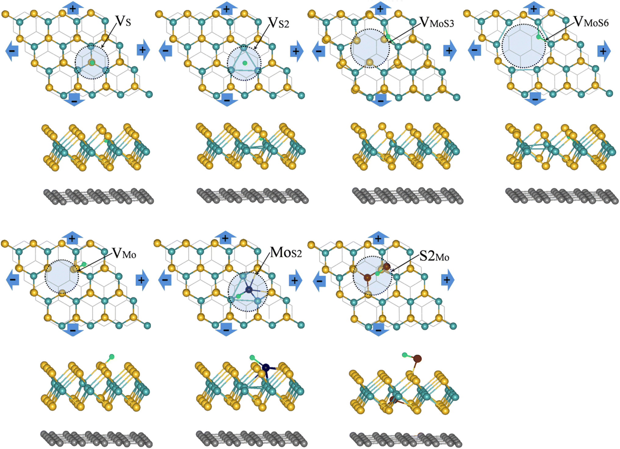 | ||
| Fig. 1 The top and side views of the most stable position for single H atom adsorbing at MoS2/graphene system with different intrinsic defects (VS, VS2, VMoS3, VMoS6, VMo, MoS2 and S2Mo, respectively) at strain engineering. The yellow, cyan and green balls present S, Mo and H atoms, respectively, the brown and dark blue balls stand for atom replaced by S and Mo atoms respectively, the bottom black line or balls refer to the graphene. | ||
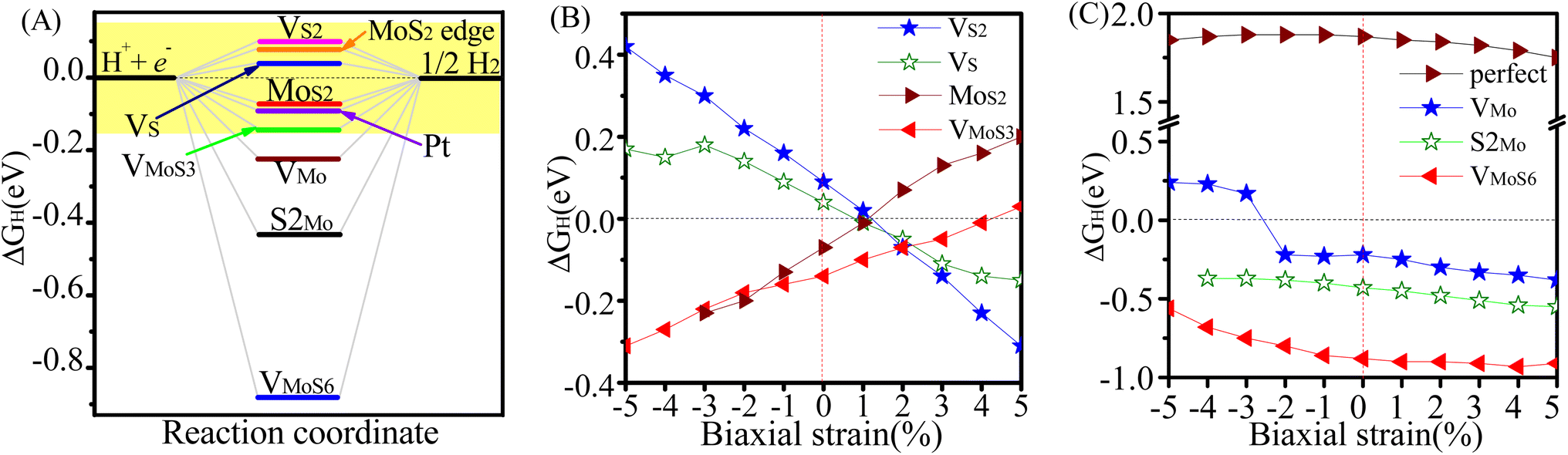 | ||
| Fig. 2 (A) ΔGH for HER on MoS2/graphene catalysts with different intrinsic defects (VS, VS2, VMo, VMoS3, VMoS6, MoS2, S2Mo), MoS2 edge and Pt, respectively. The result of Pt catalyst and MoS2 edge is taken from ref. 3. (B) ΔGH for HER on MoS2/graphene catalysts with different intrinsic defects (VS, VS2, VMoS3, MoS2) versus %x-biaxial strain ranging from −5 to +5%. (C) ΔGH for HER on perfect MoS2/graphene and MoS2/graphene systems with different intrinsic defects (VMo, S2Mo, VMoS6) versus %x-biaxial strain ranging from −5 to +5%. | ||
Next, we explored whether intrinsic defects and strain engineering simultaneously could bring better HER activity for MoS2/graphene hybrid material. We further explored the effects of biaxial strain on these defective MoS2/graphene with a series of intrinsic defects(VS, VS2, VMo, VMoS3, VMoS6, MoS2 and S2Mo). Fig. 2B and C display a variation in ΔGH under biaxial strains ranging from −5 to +5% for seven kinds of defective MoS2-graphene system by varying the lattice parameters (Fig. 1). As evident in Fig. 2, it is interesting to note that the defects have different responses to strain. As for the MoS2/graphene system with VS, VS2, VMoS3 and MoS2 defects (Fig. 2B), under biaxial strains ranging from −5 to +5%, they achieved the ideal value of ΔGH of approximately 0 eV at 1%, 1%, 4% and 1% tensile strain, respectively. It is indicated the VS, VS2, VMoS3 and MoS2 defects particularly had optimal responses to different tensile strains with optimal ΔGH values (∼0 eV) and effectively tune and boost the intrinsic activity of defective MoS2/graphene hybrid materials. In contrast, for the MoS2/graphene hybrid with the VMo, VMoS6 and S2Mo defects (Fig. 2C), when applying biaxial strains for either positive strain (tensile strain) or negative strain (compressive strain), although there is moderate drop in ΔGH, the ΔGH are all larger than |0.22 eV|, |0.5 eV| and |0.3 eV|, respectively, proved insufficient to optimize HER activity of the MoS2/graphene hybrid with the VMo, VMoS6 and S2Mo defects, responses to biaxial strains. Fig. 3 further shows the effect of strain on hydrogen binding free energy with VS–MoS2/graphene, VS2–MoS2/graphene, VMoS3–MoS2/graphene and MoS2–MoS2/graphene. It can be seen clearly, there was a negative strain (compressive strain) for the VS defect with a 3% increase of the ΔGH to 0.18 eV. It is noteworthy that, a small positive strain (tensile strain) of 1% dropped ΔGH to −0.01 eV, which is very close to the ideal value of ΔGH (0 eV). It is indicated hydrogen adsorption was significantly stronger and subsequently HER activity improved. Interestingly, in the absence of strain, the ΔGH was calculated at 0.09 eV in VS2-MoS2/graphene system. Biaxial tensile strain tends to lower the ΔGH. It appeared to catch up with that case of VS defect and eventually become significantly more active at modest tensile strain (1%) with the ideal value of ΔGH of approximately 0 eV, which is the best value for potential HER activity (Fig. 2B). The ΔGH and H adsorption strength of MoS2/graphene hybrid with VMoS3 and MoS2 defect also showed sensitivity to biaxial strain. However, biaxial tensile strain tended to weaken hydrogen adsorption for VMoS3 and MoS2, which differed from the VS and VS2 defect, where which biaxial tensile strain strengthened the hydrogen adsorption. The VMoS3 and MoS2 defect achieved a more favorable ΔGH (close to 0) at 4% and 1% tensile strain, respectively, which resulted in higher HER activity.
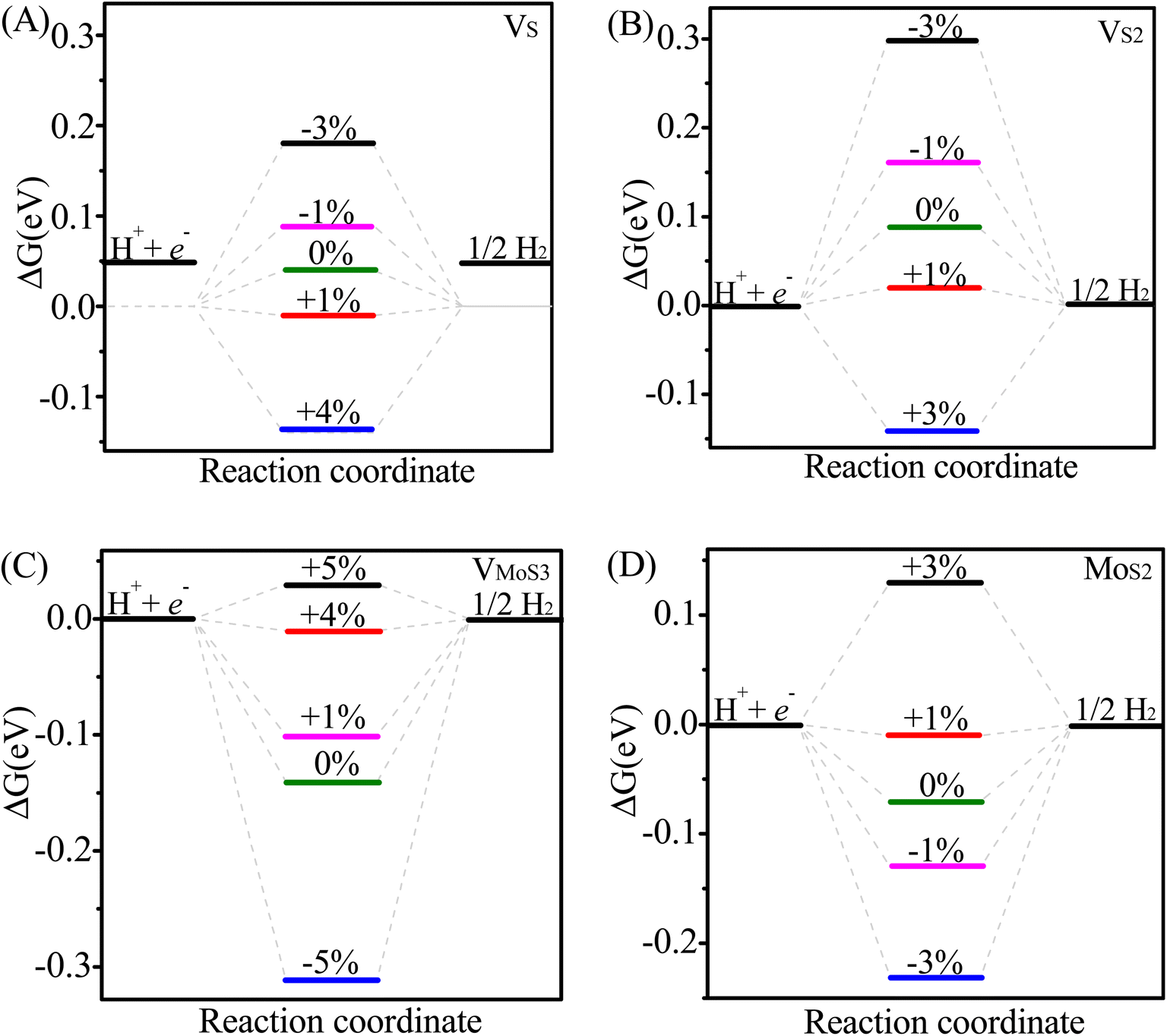 | ||
| Fig. 3 Effect of strain on the HER performance of different MoS2/graphene catalysts with different intrinsic defects (VS, VS2, VMoS3, MoS2): free energy(ΔGH) diagram for the HER on different catalysts at different strain: (A) VS-MoS2/graphene, (B) VS2-MoS2/graphene, (C) VMoS3-MoS2/graphene, (D) MoS2-MoS2/graphene. | ||
Therefore, biaxial tensile strains proves to be a good regulator for bringing the ΔGH to 0 eV and effectively tune and boost the intrinsic activity of MoS2/graphene hybrid materials with VS, VS2, VMoS3 defects and MoS2 antisite defects. The VS, VS2, VMoS3 defects and MoS2 antisite defects particular had optimal responses in the tensile-strained MoS2/graphene hybrid with optimal ΔGH values approximately 0 eV. It is indicated that combinations of defect structure and proper strain can significantly improve the HER activity of the MoS2/graphene hybrid material. These combinations were comparatively better than the defect-free MoS2/graphene under biaxial strains condition, which had ΔGH all larger than 1.60 eV when applying biaxial strains ranging from −5 to +5%. These results indicate that the strain alone is insufficient to activate the basal plane (Fig. 2C).
3.2. Electronic structures of MoS2/graphene system with the different intrinsic defects and baixial strain
To better understand the origin of the different intrinsic defects and strain engineering on the HER mechanism for defective MoS2/graphene hybrid materials, we analyzed the electronic structures of these composite materials with intrinsic defects and strain engineering. Firstly, we analyzed the electronic properties of these defective MoS2/graphene systems. The total density of states (TDOS) for MoS2/graphene system with VS, VS2, VMoS3, VMoS6 and MoS2 are investigated, as displayed in Fig. S3.† We observed there are noticeable states appearing near the Fermi level, which is significantly different from the case of defect-free MoS2/graphene system. Since hydrogen atoms directly interact with the Mo site for MoS2/graphene system with VS, VS2, VMoS3, VMoS6 and MoS2 defects, we further focused on the spin-polarized densities of states (DOS) projected on 4d states of surface active Mo atoms that participate in the interaction with the H atom in the MoS2/graphene system with VS, VS2, VMoS3, VMoS6 and MoS2, respectively (Fig. 4A). We can further conclude that the states appearing near the Fermi level is dominated by 4d state of the Mo site. When the H 1s orbital interacts with these new d states, it produces a bonding orbital and an anti-bonding orbital, where the degree of orbitals overlapping near the Fermi level determines the strength of the Mo–H chemical bonds. To understand this further, we used the d-band center theory of the metals to find an appropriate descriptor by using the d states of Mo atoms to determine the interaction strength. We then plotted the chemical bonding energy between H and the substrate, , against the value of the d band center, εd. The H adsorption energy (ΔEH) consists of two parts: the chemical bonding energy of H (
 ), and structural reconstruction energy (ΔER), so the chemical bonding energy is defined as
  . The value of εd is calculated by following equation:
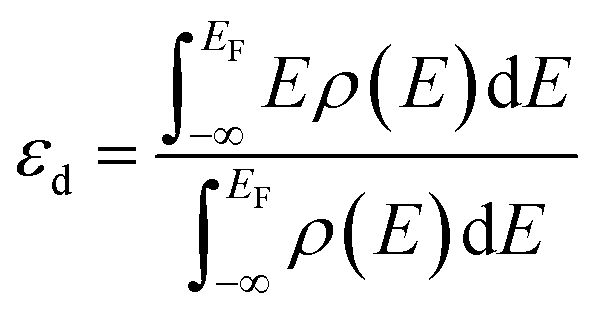 | (1) |
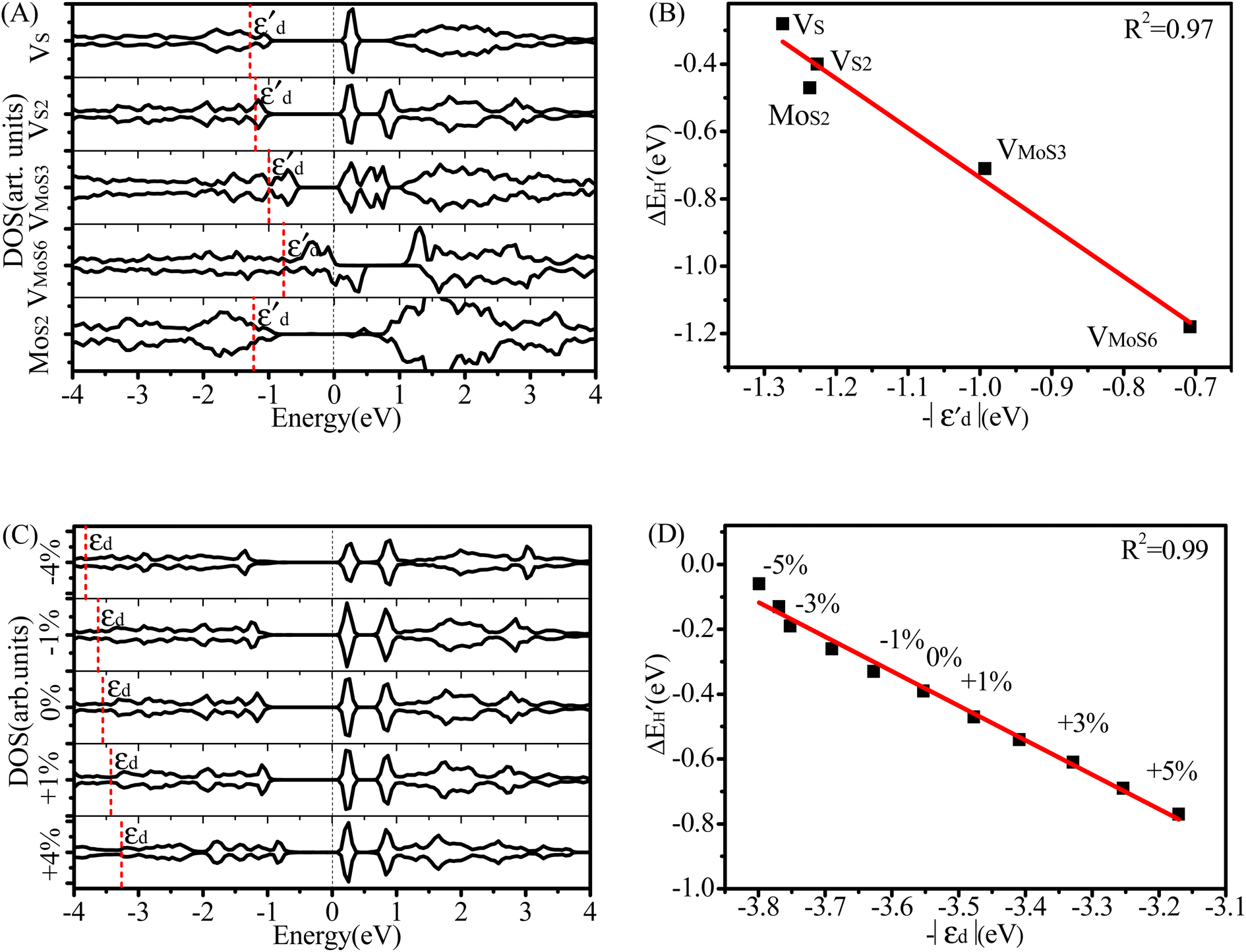 | ||
Fig. 4 (A) Spin-polarized densities of states (DOS) projected on 4d states of surface active Mo atoms for MoS2/graphene system with different intrinsic defects: VS, VS2, VMoS3, VMoS6 and MoS2, respectively. The vertical black dashed line indicates the position of the Fermi level, taken as zero energy. (B) Relationship between  and and  for various defects: VS, VS2, VMoS3, VMoS6 and MoS2 cases, respectively. (C) Spin-polarized densities of states (DOS) projected on 4d states of surface active Mo atoms for VS2-MoS2/graphene system at different biaxial strains: −4%, −1%, 0%, +1%, +4%, respectively. (D) Relationship between for various defects: VS, VS2, VMoS3, VMoS6 and MoS2 cases, respectively. (C) Spin-polarized densities of states (DOS) projected on 4d states of surface active Mo atoms for VS2-MoS2/graphene system at different biaxial strains: −4%, −1%, 0%, +1%, +4%, respectively. (D) Relationship between  and −|εd| for VS2–MoS2/graphene system under −5 to +5% biaxial strain condition. and −|εd| for VS2–MoS2/graphene system under −5 to +5% biaxial strain condition. | ||
As shown in Fig. S4,†  does not exhibit a good linear correlation with εd for defective MoS2/graphene systems with VS, VS2, VMoS3, VMoS6 and MoS2, respectively. However, when we changed the integral energy region to range of −1.5 eV–EF, named
  ,
,  displayed a nearly linear relationship with
  for the same five types of defective MoS2/graphene system (Fig. 4B), which indicates that the interaction strength between the H atom and the substrate determined by the Mo-4d state under and near the EF. As the
  more approaches EF, the Mo–H bonding more strengthens. While the other two defective MoS2/graphene systems (VMo and S2Mo defects), the H atom tend to interact directly with S atoms, and would have significant relationships between the S-3p and H-1s states. Therefore, we considered the projected DOS of S-3p state and corresponding integral energy, εp (Eqn (1)), which showed a similar H interact with S site. In the same manner, as εp more approaches EF, the S–H bonding more strengthens (Fig. S5†).
Using the VS2-MoS2/graphene system as an example, we next examined the partial DOSs of VS2-MoS2/graphene system at different biaxial strains to understand the mechanism of the variations of ΔGH tuned by strain engineering, as shown in Fig. 4C. Results show that the introduction of the strain engineering causes a visible shift of the 4d states of the Mo atom directly interacting with adsorbed H atom. The gradually shifts of the Mo-4d state are in excellent agreement with the variation of the biaxial strains. With positive strains (tensile strains), these states gradually shift upwards and move close to the Fermi level, resulting in a gradual strengthening of H binding. These states shift downward and away from the EF with negative strains (compressive strains), which can clearly explain the weakening of the H interaction with Mo atom in VS2MoS2/graphene. It is suggested that the proper tensile strain tunes the 4d state of the Mo atom, which results in a moderate ΔGH (Fig. 2B) and higher HER activity. This shows that the strain can be effectively engineered to optimize the hydrogen adsorption strength and achieve ultra-high HER activity. Next, we graphed the relationship between chemical bonding energy, ΔEbond, and the values of d band center, εd (Eqn(1)), forVS2–MoS2/graphene system under the biaxial strain condition with a range of −5 to 5% (Fig. 4D) for the purpose of analyzing Mo–H chemical bonds strength variation under the strain engineering. ΔEbond exhibits a nearly linear trend with εd of the Mo atom by a coefficient of determination of R2 = 0.99, suggesting that the strength of H binding is actually largely determined by the Mo-4d states. That the emendatory d-band center of metal can provide as an excellent descriptor for determining H adsorption is of great significance, which may pave the way to design ultrahigh-performance MoS2-based HER catalysts.
3.3. Reaction mechanism analysis
Once we have examined the Gibbs free energy for defective MoS2/Graphene hybrid materials, we next investigated the kinetic energy barriers for H2 revolution using defective VS2-MoS2/Graphene hybrid materials as a representative. The minimum-energy pathways and corresponding initial state (IS), transition state (TS) and final state (FS) are shown in Fig. 5. For HER in acid media, two types of possible pathways have been explored for H2 evolution: Volmer–Heyrovsky or the Volmer–Tafel mechanism. The Volmer reaction is the first step of the HER, in which a hydronium is transferred from the acid solution to a S2 vacancy (H+ + e− → Hads) as shown in Fig. 5A. The calculated barrier (Ea) is 0.43 eV, which is consistent with previous results.42 The Heyrovsky or Tafel mechanisms were candidates for the second step of the HER process, therefore both barriers of Tafel and Heyrovsky reaction on this active site were explored, as shown in Fig. 5B and C, respectively. In the Tafel step, two adsorbed H atoms reacted to form H2 with a barrier of 0.86 eV, which indicated that electrons could easily form H2 from the adsorbed state. The values of the Tafel reaction for VS2-MoS2/Graphene hybrid materials were much lower than the Mo-edge of a single MoS2 sheet (∼1.24 eV) reported in previous work by Huang.43 We then predicted activation barrier of 0.89 eV in the Heyrovsky step, where the proton in the water layer reacts with the adsorbed H to form H2, which is in agreement with the barrier of 0.86 eV estimated from experimental turnover frequency (TOF) for per Mo atom on the Mo edge for hydrogen evolution of MoS2.4 The ultralow kinetic barrier both for Volmer–Tafel reaction and Volmer–Heyrovsky reactions suggested that the defective VS2-MoS2/graphene system exhibits excellent HER kinetic activity.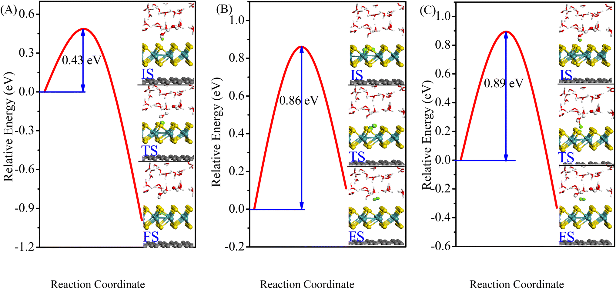 | ||
| Fig. 5 Minimum-energy pathways of Volmer, Tafel and Heyrovsky reactions on VS2-MoS2/graphene system. The inserts are the corresponding initial state (IS), transition state (TS), and final state (FS). | ||
4. Conclusions
In summary, we have verified two possible approaches to effectively activate the MoS2 basal plane grown on graphene and greatly improve hydrogen evolution reaction (HER) activity on the basis of first-principles DFT calculation, intrinsic defects and strain engineering simultaneously. We systematically investigated HER activity of MoS2/graphene hybrid material with seven experimentally produced point defects sites, VS, VS2, VMo, VMoS3, VMoS6, MoS2 and S2Mo. Our results suggest that four types of those defects (VS, VS2, MoS2, VMoS3, respectively) can act as a catalytic active site for HER and exhibit superior electrocatalytic activity. Furthermore, we demonstrated that ΔGH can be further tuned to an ideal value (∼0 eV) using intrinsic defects and a proper tensile strain simultaneously, which effectively optimizes and boosts the intrinsic HER activity of the active sites, especially for VS, VS2, VMoS3 defects and MoS2 antisite defects under the biaxial tensile strain of 1%, 1%, 4% and 1%, respectively. Interestingly, we found that the emendatory d-band center of metal can serve as an excellent descriptor to determine chemical bonding energy between H and defective MoS2/graphene hybrid material under different strain condition. Furthermore, the calculated low kinetic barrier of H2 evolution on the VS2-MoS2/graphene system indicated that the defective MoS2/graphene system exhibits excellent HER activity in both the Volmer–Heyrovsky and the Volmer–Tafel mechanisms. Therefore, the methodology of combining intrinsic defect and strain engineering has been shown to be an effective approach for producing a more catalytic active site and improving the HER activity of the MoS2/graphene hybrid and other two-dimensional materials, which may provide a new way to design ultrahigh-performance MoS2-based HER catalysts.Conflicts of interest
There are no conflicts to declare.Acknowledgements
This work was supported by National Natural Science Foundation of China (Grant No. 21863004, 22065016, 21863005, 22008096), Natural Science Foundation of Jiangxi Province (No. 20192BAB206035, 20212BAB203030), Natural Science Foundation of Jiangxi Provincial Educational Committee (GJJ170175). We are grateful for the generous allocation of computer time on the Shanxi Supercomputing Center of China, and the calculations were performed on TianHe-2.References
- J. Deng, H. Li, S. Wang, D. Ding, M. Chen, C. Liu, Z. Tian, K. S. Novoselov, C. Ma, D. Deng and X. Bao, Nat. Commun., 2017, 8, 14430 CrossRef CAS PubMed.
- H. Duan, C. Wang, G. Li, H. Tan, W. Hu, L. Cai, W. Liu, N. Li, Q. Ji, Y. Wang, Y. Lu, W. Yan, F. Hu, W. Zhang, Z. Sun, Z. Qi, L. Song and S. Wei, Angew. Chem., Int. Ed., 2021, 60, 7251–7258 CrossRef CAS PubMed.
- B. Hinnemann, P. G. Moses, J. Bonde, K. P. Jørgensen, J. H. Nielsen, S. Horch, I. Chorkendorff and J. K. Nørskov, J. Am. Chem. Soc., 2005, 127, 5308–5309 CrossRef CAS PubMed.
- J. Chen, G. Liu, Y. Zhu, M. Su, P. Yin, X. Wu, Q. Lu, C. Tan, M. Zhao, Z. Liu, W. Yang, H. Li, G. Nam, L. Zhang, Z. Chen, X. Huang, P. M. Radjenovic, W. Huang, Z. Tian, J. Li and H. Zhang, J. Am. Chem. Soc., 2020, 142, 7161–7167 CrossRef CAS PubMed.
- X. Zhang, S. Hua, L. Lai, Z. Wang, T. Liao, L. He, H. Tang and X. Wan, RSC Adv., 2022, 12, 17959–17983 RSC.
- S. Han, X. Li, X. Zeng, D. Cao and J. Chen, Int. J. Hydrogen Energy, 2022, 47, 37850–37859 CrossRef CAS.
- J. Xie, H. Zhang, S. Li, R. Wang, X. Sun, M. Zhou, J. Zhou, X. Lou and Y. Xie, Adv. Mater., 2013, 25, 5807–5813 CrossRef CAS PubMed.
- M. Remskar, A. Mrzel, Z. Skraba, A. Jesih, M. Ceh, J. Demsar, P. Stadelmann, F. Levy and D. Mihailovic, Science, 2001, 292, 479–481 CrossRef CAS PubMed.
- Y. Li, H. Wang, L. Xie, Y. Liang, G. Hong and H. Dai, J. Am. Chem. Soc., 2011, 133, 7296–7299 CrossRef CAS PubMed.
- A. Hasani, M. Tekalgne, Q. V. Le, H. W. Jang and S. Y. Kim, J. Mater. Chem. A, 2019, 7, 430–454 RSC.
- C. Gabbett, C. S. Boland, A. Harvey, V. Vega-Mayoral, R. J. Young and J. N. Coleman, Chem. Mater., 2018, 30, 5245–5255 CrossRef CAS.
- D. Voiry, R. Fullon, J. C. Yang, C. de Carvalho Castro e Silva, R. Kappera, I. Bozkurt, D. Kaplan, M. J. Lagos, P. E. Batson, G. Gupta, A. D. Mohite, L. Dong, D. Er, V. B. Shenoy, T. Asefa and M. Chhowalla, Nat. Mater., 2016, 15, 1003 CrossRef CAS PubMed.
- X. Xu, Z. Peng, H. Xu and D. Cheng, J. Catal., 2022, 416, 47–57 CrossRef CAS.
- X. Wang, Y. Zhang, H. Si, Q. Zhang, J. Wu, L. Gao, X. Wei, Y. Sun, Q. Liao, Z. Zhang, K. Ammarah, L. Gu, Z. Kang and Y. Zhang, J. Am. Chem. Soc., 2020, 142, 4298–4308 CrossRef CAS PubMed.
- C. Tsai, H. Li, S. Park, J. Park, H. Soo Han, J. K. Nørskov, X. Zheng and F. Abild-Pedersen, Nat. Commun., 2017, 10, 1038 Search PubMed.
- L. Wang, Z. Zeng, W. Gao, T. Maxson, D. Raciti, M. Giroux, X. Pan, C. Wang and J. Greeley, Science, 2019, 363, 870–874 CrossRef CAS PubMed.
- M. Escudero-Escribano, P. Malacrida, M. H. Hansen, U. G. Vej-Hansen, A. Velázquez- Palenzuela, V. Tripkovic, J. Schiøtz, J. Rossmeisl, I. E. L. Stephens and I. Chorkendorff, Science, 2016, 352, 73–76 CrossRef CAS PubMed.
- S. Maiti, K. Maiti, M. T. Curnan, K. Kim, K. Noh and J. W. Han, Energy Environ. Sci., 2021, 14, 3717–3756 RSC.
- D. B. Putungan, S. H. Lin and J. L. Kuo, Phys. Chem. Chem. Phys., 2015, 17, 21702–21708 RSC.
- H. Li, C. Tsai, A. L. Koh, L. Cai, A. W. Contryman, A. H. Fragapane, J. Zhao, H. S. Han, H. C. Manoharan, F. Abildpedersen, J. K. Nørskov and X. Zheng, Nat. Mater., 2016, 15, 48–53 CrossRef CAS PubMed.
- N. Dimakis, S. Gupta, R. Wadud and M. I. Bhatti, Comput. Mater. Sci., 2022, 205, 111234 CrossRef CAS.
- N. Dimakis, S. Gupta, R. Wadud and M. I. Bhatti, Data Brief, 2022, 42, 108054 CrossRef CAS PubMed.
- W. Zhou, X. Zou, S. Najmaei, Z. Liu, Y. Shi, J. Kong, J. Lou, P. M. Ajayan, B. I. Yakobson and J. C. Idrobo, Nano Lett., 2013, 13, 2615–2622 CrossRef CAS PubMed.
- J. Hong, Z. Hu, M. Probert, K. Li, D. Lv, X. Yang, L. Gu, N. Mao, Q. Feng and L. Xie, Nat. Commun., 2015, 6, 6293 CrossRef CAS PubMed.
- P. Joensen, E. D. Crozier, N. Alberding and R. F. Frindt, J. Phys. C: Solid State Phys., 1987, 20, 4043 CrossRef CAS.
- D. Le, T. B. Rawal and T. S. Rahman, J. Phys. Chem. C, 2014, 118, 5346–5351 CrossRef CAS.
- C. Ataca and S. Ciraci, J. Phys. Chem. C, 2011, 115, 13303–13311 CrossRef CAS.
- S. Plimpton, J. Comput. Phys., 1995, 117, 1–19 CrossRef CAS.
- P. K. Yuet and B. Daniel, J. Phys. Chem. B, 2010, 114, 13786–13795 CrossRef CAS PubMed.
- M. Heiranian, Y. B. Wu and N. R. Alurub, J. Chem. Phys., 2017, 147, 104706 CrossRef PubMed.
- R. W. Hockney and J. W. Eastwood, Computer Simulation Using Particles, Taylor & Francis, Inc., 1988 Search PubMed.
- G. Kresse and J. Hafner, Phys. Rev. B: Condens. Matter Mater. Phys., 1993, 47, 558–561 CrossRef CAS PubMed.
- G. Kresse and J. Hafner, Phys. Rev. B: Condens. Matter Mater. Phys., 1994, 49, 14251–14269 CrossRef CAS PubMed.
- G. Kresse and J. Furthmüller, Phys. Rev. B: Condens. Matter Mater. Phys., 1996, 54, 11169–11189 CrossRef CAS PubMed.
- P. E. Blöchl, Phys. Rev. B: Condens. Matter Mater. Phys., 1994, 5, 17953–17979 CrossRef PubMed.
- J. P. Perdew, K. Burke and M. Ernzerhof, Phys. Rev. Lett., 1997, 78, 1396 CrossRef CAS.
- S. Grimme, J. Antony, S. Ehrlich and H. Krieg, J. Chem. Phys., 2010, 132, 154104 CrossRef PubMed.
- P. Atkins, Physical Chemistry, Oxford University Press, Oxford, U.K., 10th edn, 2014, pp. 1−1008 Search PubMed.
- G. Henkelman, B. P. Uberuaga and H. Jónsson, J. Chem. Phys., 2000, 113, 9901–9904 CrossRef CAS.
- B. Hinneman, P. G. Moses, J. Bonde, K. P. Jørgensen, J. H. Nielsen, S. Horch, I. Chorkendorff and J. K. Nørskov, J. Am. Chem. Soc., 2005, 127, 5308–5309 CrossRef PubMed.
- C. Tsai, K. Chan, J. K. Nørskov and F. Abild-Pedersen, Surf. Sci., 2015, 640, 133–140 CrossRef CAS.
- S. Chen, X. Chen, G. Wang, L. Liu, Q. He, X. B. Li and N. Cui, Chem. Mater., 2018, 30, 5404–5411 CrossRef CAS.
- Y. Huang, R. J. Nielsen, W. A. Goddard and M. P. Soriaga, J. Am. Chem. Soc., 2015, 137, 6692–6698 CrossRef CAS PubMed.
Footnote |
| † Electronic supplementary information (ESI) available: See DOI: https://doi.org/10.1039/d2ra07363c |
| This journal is © The Royal Society of Chemistry 2023 |