 Open Access Article
Fabrication of bio-inspired metal-based superhydrophilic and underwater superoleophobic porous materials by hydrothermal treatment and magnetron sputtering†
Adham Hussein Abdullah Farea Al-akhali and
Zhengqiang Tang
 *
*
School of Mechanical Engineering, Guizhou University, Guiyang 550025, PR China. E-mail: zhengqiangtang@126.com
First published on 4th January 2023
Abstract
Oil–water separation using porous superhydrophilic materials is a promising method to circumvent the issue of oil-polluted water by separating water from oil–water mixtures. However, fabricating metal-based porous superhydrophilic materials with stable superhydrophilicity that can recover their strong hydrophilicity and have acceptable oil–water separation efficiency without complex external stimuli is still a challenge. Inspired by the anti-wetting behavior of broccoli buds, this study successfully fabricated metal-based superhydrophilic and underwater superoleophobic porous materials by hydrothermal treatment of stainless steel meshes (SSMs) combined with magnetron sputtering of metallic Ti and W. The process was then followed with annealing at 300 °C for 4 hours. The effects of coating materials, annealing temperature, and surface structure on the wetting behavior of the prepared meshes were studied and analyzed. The modified meshes exhibited unique broccoli-like microstructures coated with thin TiO2−xNx/WO3 films and showed superhydrophilicity with a 0° water contact angle (WCA) and underwater superoleophobicity with underwater oil contact angles (UOCAs) higher than 155°. They also maintained strong hydrophilicity for more than three weeks with WCAs of less than 13°. Besides, they could recover their initial superhydrophilicity with a 0° WCA after post-annealing at 80 °C for 30 minutes. Notably, the broccoli-like structures and the strong hydrophilic coatings contributed to a significant water flow rate (Q) of 3650 L m−2 h−1 and satisfactory oil–water separation efficiency of 98% for more than 15 separation cycles toward various oil–water mixtures. We believe that the presented method and fabricated material are promising and can be applied to induce hydrophilicity of various metallic materials for practical applications of oil–water separation, anti-fouling, microfluidic transport, and water harvesting.
1. Introduction
Oil is an essential source of energy and it is used daily in most industrial facilities. However, the unsafe practices of waste oil disposal, machinery operation, oil exploration, and oil transportation can result in oil-contaminated water, which causes severe damage to the ecosystem and affects the quality of human life.1–3Recently, porous superhydrophilic materials, including membranes, meshes, foams, and sponges have shown effective results in reducing the negative effects of oil-contaminated water by separating the water from oil–water mixtures.4–6 These materials can separate and adsorb the water from the oil–water mixture due to the high affinity to water and high repellence to oil simultaneously.7
Through the study of some biological surfaces with excellent superhydrophilicity and underwater superoleophobicity in nature, it is found that the synergy of micron/nano scale structure and hydrophilic surface chemical components is the key for achieving outstanding porous superhydrophilic materials for oil-in-water separation applications.8–11 On this basis, feasible approaches and materials have been designed and developed to construct superhydrophilic and underwater superoleophobic materials.12–14 For example, Xin et al. fabricated superhydrophilic and underwater superoleophobic stainless steel meshes by depositing TiO2 using liquid phase deposition (LPD).15 Their results showed that the fabricated meshes could separate various types of oil-in-water mixtures with a separation efficiency of 99%. Dong et al. also coated a stainless steel mesh with TiO2 using the sol–gel method.6 The original stainless steel mesh exhibited poor wettability to the water with a 124° WCA. In contrast, the WCA of the treated SSM decreased to almost 0°, and extremely low oil adhesion was demonstrated. In the oil–water separation tests, the treated mesh was found to separate oil from the oil–water mixture with a separation efficiency of 99% even in corrosive and harsh environments. Ye et al. fabricated superhydrophilic surfaces using a different approach based on the femtosecond laser ablation of micro-holes drilling of the titanium foil.10 The WCA on the original titanium foil was 66.3 ± 2.1°. However, when the water droplet came into contact with the treated titanium foil, it wetted the surface with a WCA of 0°. In addition, the prepared titanium foil separated the oil from the oil–water mixture with an efficiency of over 98%. This improvement in wettability and separation efficiency after laser ablation was attributed to the formation of TiO2 and the increase in surface roughness.
Despite the feasibility of the recently utilized methods in fabricating superhydrophilic and underwater superoleophobic materials for oil–water separation, there are still challenges in preparing porous metal-based superhydrophilic surfaces with desired surface structure, stable wetting behavior, low cost, and minimal secondary pollution.15–18 As compared to other methods of fabricating superhydrophilic materials, hydrothermal treatment is inexpensive, with no secondary pollution, and can create superhydrophilic surfaces with special nano/microstructures.19,20 However, the application of the hydrothermal treatment in previous studies have been limited to inducing the hydrophilicity of strong hydrophilic materials such as TiO2 and SiO2, which limits its employment for practical applications.14,16 Therefore, using the hydrothermal treatment to fabricate the desired surface structures, followed by the deposition of strong hydrophilic materials is a promising technique to control the hydrophilicity of various porous metallic surfaces for oil–water separation applications.
Among various strong hydrophilic coating materials, metal-based photosensitive materials such as TiO2 and WO3 have been widely utilized to fabricate superhydrophilic and underwater superoleophobic materials due to their ability to recover their initial strong hydrophilicity under UV or visible light illuminations.21,22 For instance, Gao et al. prepared an ultrathin composite film that exhibited superhydrophilicity and underwater superoleophobicity after UV light illumination.23 The film was based on a single-walled carbon nanotube and TiO2 nanocomposite network (SWCNTs)/TiO2 and prepared by the sol–gel process. The as-prepared (SWCNTs)/TiO2 showed poor hydrophilicity with a WCA of 82°. After one hour of irradiation by UV light, however, the WCA decreased to nearly 0° and the surface exhibited underwater superoleophobicity with UOCAs higher than 150° toward different types of oil droplets. However, it should be noted that the hydrophilicity and photo-induced superhydrophilicity of materials of this kind depend on their chemical compositions. Therefore, constructing metal-based superhydrophilic materials capable of maintaining strong hydrophilicity and recovering satisfactory separation efficiency without complex external stimuli is crucial.
Inspired by the anti-wetting behavior of broccoli buds, this work presented a simple method to construct metal-based superhydrophilic and underwater superoleophobic porous materials by the hydrothermal treatment of stainless steel meshes combined with the magnetron sputtering of metallic Ti and W materials. The coated meshes were finally post-annealed at 300 °C for 4 hours. As a result, the modified SSMs exhibited a unique broccoli-like microstructure with excellent superhydrophilicity and robust superoleophobicity underwater. Notably, they could maintain strong hydrophilicity for more than three weeks with WCAs of less than 13°, and after annealing at 80 °C for 30 minutes, the WCAs decreased to 0° again. Meanwhile, they demonstrated satisfactory oil–water separation efficiency of 98% toward various oil–water mixtures, even in corrosive HCl and NaOH solutions. Since the proposed technique is neither complex nor expensive, we believe that this method can be used to induce the hydrophilicity of metal-based surfaces for the practical application of oil–water separation, antifouling, microfluidic transportation, and water harvesting.
2. Experimental section
2.1 Materials
Commercial stainless steel meshes type 600 (Aperture size is <0.020 mm, and the wires are 0.01 and 0.04 mm in diameter) and stainless steel plates with the dimensions of 15 × 15 × 2 mm were used as substrates. In addition, paraffin liquid (C25H4NO3, 0.84 g mL−1), 1,2-dichloroethane (C2H4Cl2, 1.26 g mL−1), deionized water, petroleum ether, and ethanol were purchased from Shanghai Aladdin Biochemical Technology Co., Ltd China. Finally, titanium (Ti) and tungsten (W) target metals (pure 99.999%) were purchased from Deyang ONA new materials Co., Ltd China, and used as coating materials.2.2 Fabrication of the broccoli bud-like structures
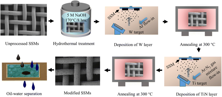
The growth of the broccoli bud-like structure was performed using a 150 mL Teflon-lined stainless steel autoclave filled with 5 M NaOH aqueous solution. First, we placed the stainless steel meshes in the autoclave. The autoclave was then moved to an oven and kept at 170 °C for two different periods of time, mainly 12 and 8 hours. Finally, the treated meshes were washed with 0.1 M HNO3 aqueous solution and ultrasonically cleaned in ethanol and deionized water for 20 minutes, respectively.2.3 Fabrication of the coatings
For the coating fabrication, Ti and W metallic targets were sputtered on the stainless steel substrates via the magnetron sputtering followed by annealing at 300 °C. Typically, a thin tungsten (W) layer was first deposited using RF magnetron sputtering and then annealed at 300 °C for 4 hours and named as W300. Subsequently, a metallic Ti target was inserted into the sputtering chamber and deposited on the W300 layer using direct current magnetron sputtering (DC) at Ar![[thin space (1/6-em)]](https://www.rsc.org/images/entities/char_2009.gif) :
:![[thin space (1/6-em)]](https://www.rsc.org/images/entities/char_2009.gif) N2 = 35
N2 = 35![[thin space (1/6-em)]](https://www.rsc.org/images/entities/char_2009.gif) :
:![[thin space (1/6-em)]](https://www.rsc.org/images/entities/char_2009.gif) 2 gas mixture. The films were then annealed at 300 °C in ambient air for 4 hours and named as TiN and TiN300 corresponding to the film before and after annealing at 300 °C, respectively. Table 1 and Fig. 1 respectively show the detailed sputtering parameters of the W and Ti metal targets and the overall fabrication process.
2 gas mixture. The films were then annealed at 300 °C in ambient air for 4 hours and named as TiN and TiN300 corresponding to the film before and after annealing at 300 °C, respectively. Table 1 and Fig. 1 respectively show the detailed sputtering parameters of the W and Ti metal targets and the overall fabrication process.
| Target material | Sputtering power (W) | Working Pressure (Pa) | Sputtering duration (min) | Substrate temperature (°C) |
|---|---|---|---|---|
| W | 150 | 0.5 | 180 | 350 |
| Ti | 200 | 0.5 | 180 | 150 |
2.4 Oil–water separation experimental setup
The oil/water separation tests were conducted using a lab-made apparatus consisting of two glass tubes. First, the SSMs were inserted between the two glass tubes with a diameter of 15 mm. Before the oil–water separation tests, the meshes were pre-wetted by water to prevent the adhesion of oils. Next, the oil/water mixture (10 mL oil and 30 mL water) was poured into the upper opened glass tube and the separation process was driven by gravity. Finally, the final amount of the collected/blocked oil was obtained to determine the amount of oil in the collected water. The separation efficiency was then calculated using:| η = (m2/m1) × 100% | (1) |
2.5 Characteristics of the fabricated films
The geometrical morphology of the SSMs was analyzed by scanning electron microscopy (SEM) ZEISS Gemini 300. For the chemical composition and elemental states, the investigation was conducted using X-ray photoelectron spectroscopy (XPS) (Thermo Scientific K-alpha). In addition, the structural property of the proposed films was investigated by X-ray diffraction (XRD) (Bruker D8 advance diffractometer). The diffraction angle (2θ) was set at the range of 10–90° under the scan rate of 5° min−1. Finally, the water contact angle (WCA) and underwater oil contact angle (UOCA) measurements were evaluated using HARKE Spcax3 contact angle analysis machine.3. Results and discussions
3.1 Wettability and characteristics of broccoli buds
The wetting behavior of some creatures in nature, including fish scales and the latus leaves, has always helped researchers to design and construct materials with special wetting behavior for practical applications.24,25 For instance, this study observed that broccoli buds exhibit strong hydrophobicity in the air with a WCA of nearly 134° as shown in Fig. 2(a). According to the Wenzel and Cassie models, this unique wetting behavior of broccoli buds might result from their capability of locking the air (air has low surface free energy) in their nano/microscale structures as shown in Fig. 2(b).26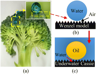 | ||
| Fig. 2 Wetting mechanism of (a) broccoli flower head, (b) hydrophobic surfaces, (c) underwater oleophobic surfaces. | ||
Comparable to the wetting mechanism of hydrophobic surfaces, the underwater Cassie model states that the wetting mechanism of superhydrophilic and underwater superoleophobic surfaces depends on locking water (water surface tension is higher than oil surface tension) rather than the air in the nano/microscale structures as shown in Fig. 2(c).27 In this respect, this study attempted to follow the anti-wetting properties of broccoli buds to fabricate underwater superoleophobic surfaces by first constructing broccoli bud-like structures on stainless steel meshes via the hydrothermal treatment. The process was then followed by fabricating thin TiO2−xNx/WO3 (TiN300) layers on the hydrothermally treated stainless steel meshes to enhance their ability to lock water (rather than air) so that they can exhibit superoleophobicity in the oil–water–solid interfaces system.
3.2 Wettability of the prepared coatings on flat surfaces
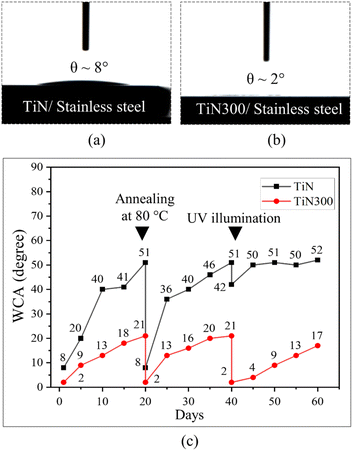
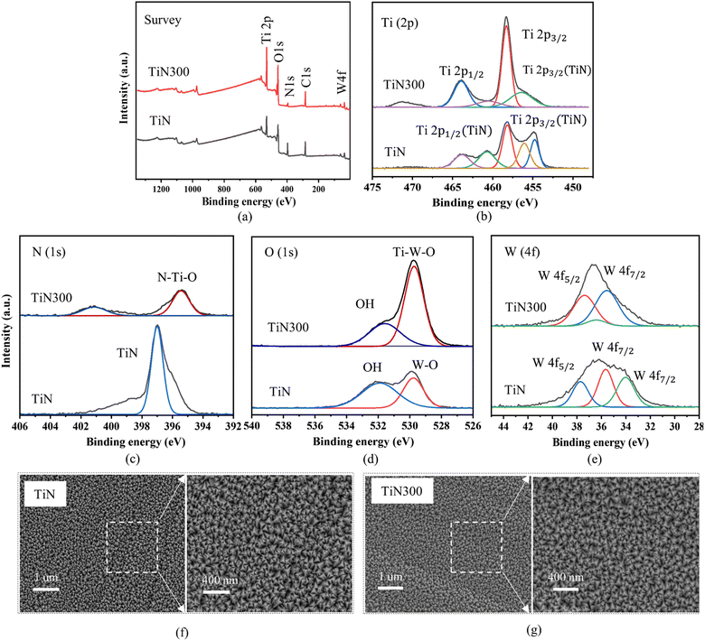
We began to demonstrate the optimal strong hydrophilic coating by depositing thin TiN and TiN300 layers on flat stainless steel samples. As shown in Fig. 3(a and b), Videos S1 and S2,† the flat stainless steel sample with a TiN layer exhibited excellent hydrophilicity in the air with a water contact angle of about 8°. After annealing at 300 °C, the surfaces demonstrated strong hydrophilicity and the WCA decreased to 2°. Interestingly, Fig. 3(c) shows that the thin TiN300 layer could maintain strong hydrophilicity for more than two weeks with a WCA of about 17° without external stimuli and less than 10° after UV light illumination for 30 minutes provided by a pressurized mercury lamp with a wavelength of (λ = 365 nm). It also could recover its initial strong hydrophilicity after annealing at 80 °C for 20 minutes as shown in Fig. 3(c), Videos S3 and S4.†According to the data from (XPS) in Fig. 4(a–e), SEM in Fig. 4(f and g), and XRD pattern in Fig. S3,† the TiN and TiN300 exhibited different chemicals composition and similar surface structures. Therefore, the difference in the WCAs could be attributed to the different chemical compositions. The XPs survey data shown in Fig. 4(a) reveals the presence of tungsten, titanium, oxygen, nitrogen, and carbon on both layers. However, the atomic percentage of these elements changed after annealing at 300 °C. As illustrated in Table S1,† the atomic percentage of Ti and O increased while the atomic percentage of C, N, and W decreased after annealing at 300 °C. The corresponding Ti (2p) high-regulation spectra in Fig. 4(b) show that the TiN layer was composed of Ti and TiN components. After annealing at 300 °C, the Ti (2p) region showed three peaks at 458.34, 463.93, and 456.3 eV binding energies. These peaks were assigned respectively to Ti4+ 2p1/2, Ti4+ 2p3/2, and Ti–N bonding, which indicated that the TiN thin film was oxidized by oxygen atoms in air.28,29 We further investigated the N (1s) states in TiN and TiN300 films. As shown in the corresponding high-resolution N (1s) spectra in Fig. 4(c), the TiN300 film showed a main peak at 395.58 eV, which originated from the N–Ti–O bond in TiN300.30–32 These results indicate that nitrogen successfully doped the TiO2 atoms in TiN after annealing at 300 °C.32,33 The core level spectra of O (1s) of TiN and TiN300 films were also investigated and shown in Fig. 4(d). We can see that the O2 spectra of TiN and TiN300 films exhibited main peaks at 529.90 and 529.79 eV corresponding to W![[double bond, length as m-dash]](https://www.rsc.org/images/entities/char_e001.gif) O and Ti–W–O bonds, respectively.34 Moreover, the shoulder peaks at 531.91 and 531.73 eV in TiN and TiN300 films were assigned to the hydroxyl group of the surface.5,28 Finally, the elemental state of the tungsten in TiN and TiN300 was investigated. As shown in Fig. 4(e), the peaks at 35.58 and 37.68 eV (BE) were respectively assigned to W4f7/2 and W4f5/2, which indicate that the W atoms were in the W6+ state.35
O and Ti–W–O bonds, respectively.34 Moreover, the shoulder peaks at 531.91 and 531.73 eV in TiN and TiN300 films were assigned to the hydroxyl group of the surface.5,28 Finally, the elemental state of the tungsten in TiN and TiN300 was investigated. As shown in Fig. 4(e), the peaks at 35.58 and 37.68 eV (BE) were respectively assigned to W4f7/2 and W4f5/2, which indicate that the W atoms were in the W6+ state.35
Following the XPS and SEM data analysis, the strong hydrophilicity of the TiN300, therefore, might result from its high hydroxyl group content, low carbon content, the presence of N-doping in TiO2, and the presence of WO3 under N-doped TiO2. As reported by previous studies, the presence of hydroxyl groups increases hydrogen bonding with water which is a key rule for enhancing hydrophilicity. In addition, N-doped TiO2 and WO3 under TiO2 were found to exhibit better photo-induced superhydrophilicity compared to pure TiO2, even under typical light illumination, due to the photosensitivity of N-doped TiO2 and WO3.36–39 In the case of the restoration of strong hydrophilicity after annealing at 80 °C and ultraviolet light illumination, it may be due to the removal of the low surface energy dirt contamination.9,23
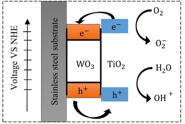
The photo-induced hydrophilicity of the TiO2/WO3 can be explained by Fig. 5. During the UV illumination, the electrons generated in TiO2 transfer to WO3, while the holes generated in WO3 transfer to TiO2 due to the large positive potential of the balance and conduction bands of WO3.40,41 Meanwhile, the photo-induced holes in TiO2 react with water and generate – OH radicals, which oxidize organic compounds on the surface of TiO2 and increase the hydrogen bonds with water, which determines the hydrophilicity.41,42
3.3 Surface characterization and wetting behavior of stainless steel meshes
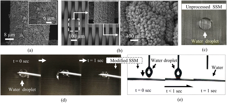
The thin TiN300 layer was then fabricated on the hydrothermally treated SSMs. As shown in Fig. 6(a), the hydrothermally treated for 12 hours SSM with TiN300 film was covered with flake nanoparticles and irregular broccoli-like hierarchal structures. By reducing the hydrothermal treatment time to 8 hours, the SSM with a thin TiN300 film was successfully covered with dense and uniform broccoli-like structures as shown in Fig. 6(b). In addition, each broccoli-like microstructure was totally covered with bud-like nanoparticles.The corresponding wetting investigations of the unprocessed SSM and the hydrothermally treated for 8 hours SSM coated with a thin TiN300 film are presented in Fig. 6(c–e). We can see that the unprocessed stainless steel mesh in Fig. 6(c) exhibited poor wettability with a WCA of about 78°. In contrast, the modified SSM in Fig. 6(d and e) showed remarkable superhydrophilicity with a 0° WCA, which was less than the WCA on the TiN300 film on flat stainless steel samples. Besides, it absorbed the water droplet in less than one second, which confirms their superhydrophilicity (Video S5†).
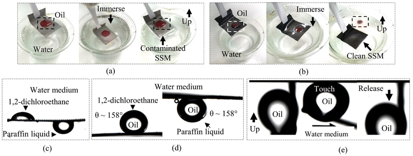
Subsequently, we carried out oil contact angle measurements and oil adhesion tests for the SSMs before and after modification. Before the tests, all the stainless steel meshes were pre-wetted with deionized water. As shown in Fig. 7(a and c), the unprocessed SSM exhibited poor self-cleaning and underwater oleophobicity with UOCAs less than 120°. The oil contaminated the mesh and strongly adhered to its surface, even after immersion in a water bath. In contrast, the modified SSM experienced satisfactory anti-fouling performance and underwater oleophobicity. The oil droplet on the modified SSM slid off immediately after immersion in water as shown in Fig. 7(b). This anti-fouling was confirmed by the underwater oil contact angle (UOCA) measurements and oil adhesion tests shown in Fig. 7(d and e). We can see that the modified SSM expressed UOCAs higher than 155° toward paraffin liquid and 1,2-dichloroethane droplets, and also no trace of oil was observed after the oil adhesion test as shown in Fig. 7(e).
The fascinating superhydrophilicity and underwater superoleophobicity of the freshly modified SSMs resulted from the abundant hydroxyl group in TiN300 and the unique broccoli bud-like rough structure. The rule of surface roughness in inducing hydrophilicity can be explained by the Wenzel model shown in Fig. 8(b). Simply, the increase of surface roughness after the hydrothermal treatment increased the solid–water contact area, which enhanced the hydrophilicity.43 The WCA on the rough surface can be calculated using eqn (2) as follows:
cos![[thin space (1/6-em)]](https://www.rsc.org/images/entities/char_2009.gif) θr = r θr = r![[thin space (1/6-em)]](https://www.rsc.org/images/entities/char_2009.gif) cos cos![[thin space (1/6-em)]](https://www.rsc.org/images/entities/char_2009.gif) θ θ
| (2) |
 | ||
| Fig. 8 Schematic illustration of the wetting states (a) flat surface with water in air, (b) rough surface with water in air, (c) rough surface with oil in water. | ||
Underwater, the anti-oil adhesion behavior of the modified SSMs can be explained based on the modified underwater Cassie–Baxter model.44 As shown in Fig. 8(c), the strong hydrophilic TiN300 film and the presented broccoli bud-like structures absorbed the water to form a thin water-film, which prevented the oil adhesion due to the repulsive behavior of water toward oil. The underwater oil contact angle on a rough-hydrophilic surface (θOWr) can be evaluated using the Cassie–Baxter equation as follows:45
cos![[thin space (1/6-em)]](https://www.rsc.org/images/entities/char_2009.gif) θOWr = f θOWr = f![[thin space (1/6-em)]](https://www.rsc.org/images/entities/char_2009.gif) cos cos![[thin space (1/6-em)]](https://www.rsc.org/images/entities/char_2009.gif) θOW + f − 1 θOW + f − 1
| (3) |
 | (4) |
3.4 Oil-in-water separation test
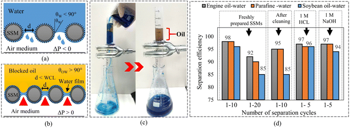
The oil–water separation mechanism using superhydrophilic materials can be explained using the Young–Laplace theory and Fig. 9(a) as follows:45,47
 | (5) |
According to eqn (5) and Fig. 9(a), the water can penetrate the porous material without external pressure as the intrinsic WCA on the porous material is less than 90°. On the other hand, if the WCA is much higher than 90°, external pressure is required to force the water to penetrate the porous material.
Similarly, the ability of a hydrophilic porous material in blocking oil in the oil–water–sold interfaces system can be explained by the following equation:
 | (6) |
Based on eqn (6), when θOW is higher than 90°, external pressure is required to allow the oil to penetrate the porous material. In addition, eqn (5) and (6) show that the pore size is an essential factor that affects the oil and water penetration. When the pore size (d) is much smaller than the water capillary length (WCL), a continuous water-film (colored blue in Fig. 9(b)) can be formed between the adjacent wires.48 This thin water film can drive the water through the porous material due to the capillary effect.49 Meanwhile, it can block oils due to the repellent property of water toward oil.7 However, if the pore size is much larger than the capillary length of the water, the water film can break off so that both water and oil may penetrate.50,51 Besides, the continuous water-film can only block a certain amount of oil before it is disrupted by the pressure of the blocked/accumulated oil. The actual break-through pressure (ΔPo-act) related to the accumulated oil on porous materials can be calculated using the following equation:5
| ΔPo-act = ρghmax | (7) |
The flux permission (J) of porous materials is an important characteristic to determine their penetration capacity. The relation among the permission flux (J), porosity (ε), pores radius (rP), viscosity of the liquid (μ), and pressure drop ΔP can be elucidated using Hagen–Poiseuille's equation as follows.47
 | (8) |
According to eqn (8), the flux permission will increase as the pore size, porosity, and applied pressure increase. However, as mentioned earlier, if the pore size is larger than the water capillary length, the continuous water-film between the adjacent wires may break off and affect the oil–water separation efficiency. Therefore, for achieving high oil–water separation performance, the pressure drop (ΔP) in eqn (8) must be greater than the breakthrough pressure of water (ΔPW) and smaller than the breakthrough pressure of oil (ΔPO).
Finally, the actual flow rate (Q) of the water passing porous materials can be estimated using eqn (9) as follows:52
| Q = V/At | (9) |
To test the oil–water separation efficiency of the SSMs before and after modification, three oil–water mixtures were prepared by mixing 30 mL of deionized water with 10 mL of different oils, including paraffin liquid, 1,2-dichloroethane, and engine oil. The separation process is shown in Fig. 9(c). Before the separation tests, we pre-wetted all the SSMs with deionized water to prevent oil adhesion on their surfaces. The pre-wetting process revealed that the modified SSM exhibited high water flow rate (Q) of about 3650 L m−2 h−1, compare with 1633 L m−2 h−1 for the unprocessed SSM (Video S6†). During the oil–water separation tests, the waited time between each separation cycle was maintained at one minute. Finally, the blocked oil was collected to estimate the amount of oil in the penetrated water using eqn (1). The results showed that the unprocessed SSM experienced poor oil–water separation performance of less than 40% toward the oil–water mixtures as shown in Fig. S5(a).† In contrast, the modified SSM exhibited considerable separation efficiency of 98% for the first 10 separation cycles and decreased to less than 85% after 20 separation cycles as shown in Fig. 9(c), Video S7, and Fig. S5(b).† This separation efficiency was recovered to 95% for another 10 separation cycles after ultrasonic cleaning in petroleum ether, ethanol, and deionized water for 10 minutes each, and finally, UV illumination under a high-pressure mercury lamp for 30 minutes as shown in Fig. 9(c). It was also observed that the modified mesh could block a certain amount of oil to a certain height (hmax) before it allowed the oil to penetrate as shown in Fig. S5(c).† The maximum amount of the accumulated oil was measured for the engine oil with a maximum high (hmax) of about 17 cm and equivalent to actual break-through pressure (ΔPo-act) of 1.451 kPa. Table 2 shows the hmax of each blocked oil and their ΔPo-act. Finally, the separation efficiency toward oil-in-corrosive aqueous solutions, mainly 1 M HCl and 1 M NaOH, was also investigated and shown in Fig. 9(c) and S5(d).† We can see that the modified mesh could keep high separation efficiency of about 97% for the first five separation cycles. The worst separation efficiency was observed for the soybeans oil-in-1 M NaOH.
| Type of oil | Engine oil | Paraffin liquid | Soybean oil | |||
|---|---|---|---|---|---|---|
| Parameter | ΔPo-act (kPa) | hmax (cm) | ΔP (kPa) | hmax (cm) | ΔP (kPa) | hmax (cm) |
| Value | 1.451 | 17 | 1.319 | 16 | 1.125 | 12.5 |
4. Conclusions
In summary, this article presented a facial method to construct bio-inspired metal-based superhydrophilic meshes by the combined actions of the hydrothermal treatment, magnetron sputtering, and annealing. The experimental results showed that annealing at 300 °C oxidized both W and TiN films and resulted in the formation of the WO3 and N-doped TiO2. The annealed films contained more hydroxyl groups which enhanced their strong hydrophilicity. Besides, when the prepared films were subjected to post-annealing at 80 °C after three weeks, they recovered their initial high hydrophilicity. These results have shown that the combined action of magnetron sputtering and annealing is a promising technique for constructing strong metal-based hydrophilic materials that can recover their strong hydrophilicity without the need for complex external stimuli. In addition, the broccoli-like structure was crucial to enhance the hydrophilicity of the TiN300 film and endowed the SSMs with stable and strong hydrophilicity, as well as satisfactory oil–water separation.Author contributions
The authors confirm their contribution to the paper as follows: study conception, designs excrements, data collection, analysis, and interpretation of results: Adham Hussein Abdullah Farea AL-AKHALI. Drafted the article or revised it critically for important intellectual content, approved the version to be published: Zhengqiang TANG: all authors reviewed the results and approved the final version of the manuscript.Conflicts of interest
The authors have no competing interests to declare that are relevant to the content of this article.Acknowledgements
This work is supported by the National Science Foundation of China (52165022), the Science and Technology Project of Guizhou Province ([2020]1Y415), and the incubation project of Guizhou University ([2019]24).References
- M. Cheryan and N. Rajagopalan, J. Membr. Sci., 2015, 151, 13–28 CrossRef.
- Z. Gong, N. Yang, Z. Chen, B. Jiang, Y. Sun, X. Yang and L. Zhang, Chem. Eng. J., 2020, 380, 122524 CrossRef CAS.
- K. H. Ha and C. N. Chu, J. Micromech. Microeng., 2016, 26, 045008 CrossRef.
- L. Zhang, X. Yang, B. Jiang, Y. Sun, Z. Gong, N. Zhang, S. Hou, J. Li and N. Yang, Appl. Surf. Sci., 2018, 456, 114–123 CrossRef.
- C. Zhou, Y. Li, H. Li, X. Zeng, P. Pi, X. Wen, S. Xu and J. Cheng, Surf. Coat. Technol., 2017, 31, 55–62 CrossRef.
- Z. Dong, B. Wang, M. Liu, X. Ma and Z. Xu, RSC Adv., 2016, 6, 65171–65178 RSC.
- X. Du, Q. Wang and X. Wang, Surf. Coat. Technol., 2018, 358, 806–816 CrossRef.
- J. Wang and H. Wang, Sep. Purif. Technol., 2017, 195, 358–366 CrossRef.
- J. Drelich, E. Chibowski, D. Meng and K. Terpilowski, Soft Matter, 2011, 7, 9804–9828 RSC.
- S. Ye, Q. Cao, Q. Wang, T. Wang and Q. Peng, Sci. Rep., 2016, 6, 37591 CrossRef CAS PubMed.
- J. Dai, L. Wang, Y. Wang, S. Tian, X. Tian, A. Xie, R. Zhang, Y. Yan and J. Pan, ACS Appl. Mater. Interfaces, 2020, 12, 4482–4493 CrossRef CAS PubMed.
- V. Zorba, X. Chen and S. Mao, Appl. Phys. Lett., 2010, 96, 093702 CrossRef.
- H. Eshaghi and A. Eshaghi, Bull. Mater. Sci., 2012, 35, 137–142 CrossRef.
- B. U. Gunatilake and J. Bandara, Chemosphere, 2017, 171, 134–141 CrossRef PubMed.
- D. Xin, Q. Wang and X. Wang, Surf. Coat. Technol., 2019, 358, 806–816 CrossRef.
- Q. Wen, J. Yu, X. Sun, J. Zhuang, Q. He, X. You, J. Guo and L. Tao, New J. Chem., 2016, 40, 3233–3237 RSC.
- Y. Wang, S. Wang, D. Liu, L. Zhou, R. Du, T. Li, T. Miao, J. Qian, Y. Hu and S. Huang, Chem. Commun., 2020, 56, 8750–8753 RSC.
- J. Ding, L. Zhong, Q. Huang, Y. Guo, T. Miao, Y. Hu, J. Qian and S. Huang, Carbon, 2021, 177, 160–170 CrossRef CAS.
- Y. Xing, L. E, L. Lai, D. Zhao and J. Wang, J. Mater. Sci.: Mater. Electron., 2021, 32, 5156–5164 CrossRef CAS.
- Y. Gao, M. Hu and B. Mi, J. Membr. Sci., 2014, 455, 349–356 CrossRef CAS.
- R. Asahi, T. Morikawa, H. Irie and T. Ohwaki, Chem. Rev., 2014, 114, 9824–9852 CrossRef CAS PubMed.
- R. Wang, K. Hashimoto, A. Fujishima, M. Chikuni, E. Kojima, A. Kitamura, M. Shimohigoshi and T. Watanabe, Nature, 1997, 388, 431–432 CrossRef CAS.
- S. J. Gao, Z. Shi, W. B. Zhang, F. Zhang and J. Jin, ACS Nano, 2014, 8, 6344–6352 CrossRef CAS PubMed.
- J. Yong, F. Chen, Q. Yang, D. Zhang, U. Farooq, G. Dua and X. Hou, J. Mater. Chem. A, 2014, 2, 8790–8795 RSC.
- G. Li, Y. Lu, P. Wu, Z. Zhang, J. Li, W. Zhu, Y. Hu, D. Wu and J. Chu, J. Mater. Chem. A, 2015, 3, 18675–18683 RSC.
- G. S. Boltaev, S. A. Khan, R. A. Ganeev, V. V. Kim, M. Iqbal and A. S. Alnaser, Appl. Phys. A: Mater. Sci. Process., 2020, 126, 26 CrossRef.
- J. Yong, F. Chen, Q. Yang, J. Huoa and X. Hou, Chem. Soc. Rev., 2017, 46, 4168–4217 RSC.
- C. Stegemann, R. Moraes, D. A. Duarte and M. Massi, Thin Solid Films, 2017, 62, 49–55 CrossRef.
- B. Bharti, S. Kumar and R. Kumar, Appl. Surf. Sci., 2016, 364, 51–60 CrossRef CAS.
- M. Dobromir, A. V. Manole, V. Nica, R. Apetrei, M. Neagu and D. Luca, Sens. Lett., 2013, 11, 675–678 CrossRef CAS.
- H. Fakhouri, J. Pulpytel, W. Smith, A. Zolfaghari, H. R. Mortaheb, F. Meshkini, R. Jafari, E. Sutter and F. Arefi-Khonsari, Appl. Catal., B, 2014, 144, 12–21 CrossRef CAS.
- H. Irie, S. Washizuka, N. Yoshinob and K. Hashimoto, Chem. Commun., 2003, 11, 1298–1299 RSC.
- H. Irie, S. Washizuka, Y. Watanabe, T. Kako and K. Hashimoto, J. Electrochem. Soc., 2005, 152, 351–356 CrossRef.
- Y. Shen, T. Xiong, T. Li and K. Yan, Appl. Catal., B, 2008, 83, 177–185 CrossRef CAS.
- D. Song, Z. Chen, P. Cui, M. Li, X. Zhao, Y. Li and L. Chu, Nanoscale Res. Lett., 2015, 10, 16 CrossRef PubMed.
- T. Morikawa, R. Asahi, T. Ohwaki, K. Aoki, K. Suzuki and Y. Taga, R&D Rev. Toyota CRDL, 2005, 40(3) Search PubMed.
- K. Zhao, Z. Wu, R. Tang and Y. Jiang, J. Korean Chem. Soc., 2013, 57, 489–492 CrossRef CAS.
- R. Asahi, T. Morikawa, H. Irie and T. Ohwaki, Chem. Rev., 2014, 114, 9824–9852 CrossRef CAS PubMed.
- J. J. Park, D. Y. Kim, S. S. Latthe, J. G. Lee, M. T. Swihart and S. S. Yoon, ACS Appl. Mater. Interfaces, 2013, 5, 6155–6160 CrossRef CAS PubMed.
- Y. A. K. Reddy, B. Ajith, A. Sreedhar and E. Varrlad, Appl. Surf. Sci., 2019, 494, 575–582 CrossRef CAS.
- A. B. Youssef, N. Barbana, M. Al-Addous and L. Bousselmi, J. Mater. Sci.: Mater. Electron., 2018, 29, 19909–19922 CrossRef.
- M. Miyauchi, A. Nakajima, T. Watanabe and K. Hashimoto, Chem. Mater., 2002, 14, 2812–2816 CrossRef CAS.
- J. Yong, Q. Yang, C. Guo, F. Chen and X. Hou, RSC Adv., 2019, 9, 12470–12495 RSC.
- J. Yong, F. Chen, Q. Yang, D. Zhang, U. Farooq, G. Dua and X. Hou, J. Chem., 2014, 2, 8790–8795 CAS.
- F. Li, W. Kong, X. Zhao and Y. Pan, ACS Appl. Mater. Interfaces, 2020, 12, 18074–18083 CrossRef CAS PubMed.
- I. E. Palamà, S. D'Amone, V. Arcadio, D. Caschera, R. G. Toro, G. Gigli and B. Cortese, J. Mater. Chem. A, 2015, 3, 3854–3861 RSC.
- S. Mosadegh-Sedghi, D. Rodrigue, J. Brisson and M. C. Iliuta, J. Membr. Sci., 2014, 452, 332–353 CrossRef CAS.
- B. Kim and P. Harriott, J. Colloid Interface Sci., 1987, 115, 1–8 CrossRef CAS.
- A. Xie, J. Cui, Y. Chen, J. Lang, C. Li, Y. Yan and J. Dai, Sep. Purif. Technol., 2018, 215, 1–9 CrossRef.
- R. J. Good and M. Islam, Langmuir, 1991, 7, 3219–3221 CrossRef CAS.
- D. Weng, A. Mahmood, S. Chen and J. Wang, ACS Appl. Mater. Interfaces, 2019, 11, 11006–11027 CrossRef PubMed.
- P. Yu, Z. Lian, J. Xu, Z. Yu, W. Ren and H. Yu, Mater. Res. Express, 2018, 5, 045013 CrossRef.
Footnote |
| † Electronic supplementary information (ESI) available. See DOI: https://doi.org/10.1039/d2ra07113d |
| This journal is © The Royal Society of Chemistry 2023 |

