
 Open Access Article
 This Open Access Article is licensed under a Creative Commons Attribution-Non Commercial 3.0 Unported Licence
Graphene quantum dots functionalised with rhamnolipid produced from bioconversion of palm kernel oil by Pseudomonas stutzeri BK-AB12MT as a photocatalyst†
Fera Faridatul Habibah a,
Atthar Luqman Ivansyahb,
Samuel Ivana and
Rukman Hertadi*a
a,
Atthar Luqman Ivansyahb,
Samuel Ivana and
Rukman Hertadi*a
aBiochemistry Research Division, Chemistry Department, Bandung Institute of Technology, Bandung 40132, Indonesia. E-mail: rhertadi@itb.ac.id
bAnalytical Chemistry Research Division, Chemistry Department, Bandung Institute of Technology, Bandung 40132, Indonesia
First published on 18th January 2023
Abstract
Methylene blue (MB) is a common organic dye found in textile wastewater and can harm the environment. Rhamnolipid-functionalized graphene quantum dots (RL-GQDs) are a newly developed eco-friendly photocatalyst to degrade MB. This photocatalyst is synthesized from graphene quantum dots (GQDs) and rhamnolipid. GQDs are already promising visible-light photocatalysts to degrade organic dyes. However, GQDs are not promising photocatalysts due to their reusability and photocatalytic performance. In this work, we used rhamnolipid to modify GQDs' structure and enhance their photocatalytic performance. The rhamnolipid used in this work was produced from bioconversion of palm kernel oil by mutated bacterial cells of Pseudomonas stutzeri BK-AB12MT. Meanwhile, GQDs were synthesized using the bottom-up method by pyrolysing citric acid. Transmission electron microscopy and Fourier-Transform Infrared spectroscopy were used to characterize these hybrid materials. These characterization techniques verified the formation of RL-GQDs. To prove the photocatalytic performance of RL-GQDs, we investigated the photocatalytic activity under visible light compared to some common photocatalysts, such as zinc oxide and titanium dioxide. Our findings showed that RL-GQDs could be applied as an eco-friendly photocatalyst to replace TiO2 with a degradation efficiency of 59% ± 3% under visible light irradiation, higher than TiO2.
1. Introduction
Synthetic dyes are components widely used in industry. Their production grows by 10![[thin space (1/6-em)]](https://www.rsc.org/images/entities/char_2009.gif) 000 tons per year. However, due to large-scale production and wide application, synthetic dyes can cause environmental pollution and health-risk because significant amounts of unused dyes are left in wastewater.1,2 Methylene blue (MB) is a synthetic dye commonly used for coloring paper, dyeing cotton, wools, silk, leather, and paper coating stock in the textile industry. It can cause several harmful effects on humans such as eye burn, irritation, and diarrhea. MB is a cationic thiazine dye, which has higher toxicity levels than anionic dyes. Hence, removing MB from wastewater to an acceptable environmental level is important.
000 tons per year. However, due to large-scale production and wide application, synthetic dyes can cause environmental pollution and health-risk because significant amounts of unused dyes are left in wastewater.1,2 Methylene blue (MB) is a synthetic dye commonly used for coloring paper, dyeing cotton, wools, silk, leather, and paper coating stock in the textile industry. It can cause several harmful effects on humans such as eye burn, irritation, and diarrhea. MB is a cationic thiazine dye, which has higher toxicity levels than anionic dyes. Hence, removing MB from wastewater to an acceptable environmental level is important.
Currently, several standard methods are used to remove dyes from wastewater, such as adsorption, photocatalytic decolorisation and oxidation, microbiological decomposition, and enzymatic decomposition.1 Among all methods, photocatalysis offers several advantages, including environmental protection, complete degradation of pollutants, and no secondary pollution.3 It is commonly used to remove both cationic and anionic dyes. This method utilizes oxidative process and occurs on organic pollutants quickly and non-selectively.4 Commonly, photocatalysis uses inorganic materials such as titanium dioxide (TiO2) and zinc oxide (ZnO). TiO2 has proven to be a promising n-type semiconductor due to its wide bandgap under ultraviolet (UV) light.5 It also has high physical, chemical, and photochemistry stability, so it has been widely studied and has become a powerful catalyst candidate.6,7 However, TiO2 is only active in the near-UV caused by its wide bandgap, limiting its utility to environments with significant UV light flux.8 Therefore, researchers tried to use alternative materials such as ZnO to substitute TiO2. ZnO was more photochemically active, leading to a higher photocatalytic efficiency than TiO2.9 Furthermore, TiO2 and ZnO have similar limitations concerning low adsorption of organic pollutants, significant aggregation of nanosized particles, difficulty in removing those from the catalyst surface, and a significant bandgap value issue that necessitates high activation energy. Aside from those problems, metal oxide photocatalysts face adverse environmental effects, such as phytotoxic effects on several plant species,10 reducing microbial biomass, and altering soil bacterial community diversity and composition.11
Recent studies proposed novel photocatalyst systems to maximise the utilisation of visible light that are eco-friendly and mild character in nature, have fewer by-products, and have highly compatible functional-groups.12–14 Among various novel photocatalyst systems, carbon-based quantum dots (CQDs) are promising alternatives to metal oxide photocatalysts due to their strong and tunable fluorescence emission properties, redox properties, stability, low toxicity, and facile tunability.15
GQDs are one kind of CQDs that have widely studied for their novel and unique properties, such as optical, electrical, and optoelectrical properties. GQDs offer ultrahigh specific surfaces due to the nano-sized single-layer graphene sheets and low toxicity.16 Similar to other quantum dots materials, GQDs have been used in solar cells,17 photodetectors,18 bioimaging, fluorescent agents,19 light-emitting diodes (LEDs),20 batteries,21 sensors,22 drug carriers,23 and photo-/electro-catalytic.24,25 Kundu and Pillai stated that GQDs are eco-friendly materials and have potential as the next generation nanocarbon materials because of their large application fields.26 GQDs are also more sensitive to environmental changes. Thus, GQDs are superior compared to typical carbon materials. They have also been developed as photocatalyst. Ibarbia et al. used bare GQDs as a water-soluble photocatalyst, showing that GQDs have great rhodamine B degradation efficiency.27 Although GQDs had shown such potential as a photocatalyst, they cannot be recovered due to their high solubility in water. This phenomenon challenges the researchers to improve GQDs as a water-insoluble supporting material photocatalyst. Hence, it will ease to recovery and reuse of the photocatalyst.
Researchers either functionalized or composited GQDs with other materials such as zinc porphyrin,28 CdSe29 and ZnO nanowire to enhance its activity and recovery properties.30 The functionalization of GQDs affects their optical, chemical, and electronic properties resulting in an excellent photocatalyst. In addition, Yao et al. proposed to use surfactants to enhance the adsorption activities of GQDs. There are several advantages to using surfactants in the adsorption of nonionic organic species, such as (1) the aggregation of GQDs can be effectively inhibited, (2) accessible entrance of nonionic organic adsorbates by hydrophobic interaction, and (3) surfactants will protect the functional group of GQDs from disturbance of water molecule, thus facilitating the formation of hydrogen bond between GQDs and nonionic organic adsorbates. Unfortunately, the most used surfactants are petroleum-based. Petroleum-based surfactants are chemically synthesized from the petrochemical industry.31 This type of surfactant is not environmentally friendly due to its residue and is slowly microbial degradation.32 One of the solutions to solve this problem is to functionalise GQDs with biosurfactants.
Biosurfactant is a secondary metabolite produced by microorganisms at a limited nutrient condition such as phosphate and nitrogen sources, but a rich source of an immiscible substrate such as alkanes and fatty acids. Rhamnolipid is one of the glycolipid biosurfactant that is widely used in the petroleum industry (33%), cosmetics (15%), bioremediation (11%), and antimicrobe and drugs (12%).33 In the photocatalyst field, rhamnolipid is also a promising material. A recent study by Bhosale et al.34 rhamnolipid has been used to modify iron oxide nanoparticles (RL@IONPs) as a potential photocatalyst due to the decolorization of methyl violet dye. Rhamnolipid served as a suitable candidate to lower magnetic nanoparticles and prevent the oxidation of magnetic nanoparticles. The RL@IONPs proved as an eco-friendly photocatalyst to treat large amounts of wastewater within a short time.
To the best of our knowledge, the report about GQDs functionalization with rhamnolipid remains scarce. In this work, we suggest the functionalization of GQDs with rhamnolipid produced from bioconversion of palm kernel oil (PKO) by Pseudomonas stutzeri BK-AB12MT to be a potential photocatalyst to degrade MB. P. stutzeri BK-AB12MT was one of the bacterial collections in our laboratory. This bacterium mutated from the wildtype (WT, P. stutzeri BK-AB12) found in the salty mud crater at Bledug Kuwu Village, Central Java, Indonesia.35 The GQDs were synthesized using citric acid (CA) as the precursor. The CA was pyrolyzed to produce GQDs. This synthesis route is called bottom-up method.36
Hence, we developed an easy and low-cost method to synthesize rhamnolipid-functionalized GQDs (RL-GQDs). Owing to the low toxicity of both precursors (GQDs and rhamnolipid), we also studied RL-GQDs’ potency as an eco-friendlier photocatalyst compared to several highly toxic commercial photocatalysts.37
2. Materials and methods
2.1 Materials
Materials used for nanohybrid synthesis were 2-(N-morpholino)ethane sulfonic acid (MES), 4-(dimethyl amino)pyridine (DMAP) (Sigma-Aldrich), N-(3-dimethylaminopropyl)-N′-ethyl carbodiimide hydrochloride (EDC) (Sigma-Aldrich), tetra-n-butyl titanate (TBT) (Sigma-Aldrich), Tween-80 (Merck), sodium hydroxide (NaOH) (Merck), citric acid (C6H8O7) (Merck), chloroform (CHCl3) (Merck), methanol (CH3OH) (Merck), ethanol (C2H5OH) (Merck), zinc acetate (Zn(CH3COO)2) (Merck), methylene blue (C16H18ClN3S) (Merck), and standard rhamnolipid R90G purchased from AGAE Technologies LLC. All materials purchased and used were ACS Grade Material.The growth medium used was Luria–Bertani (LB) liquid medium containing 0.5% (w/v) yeast extract, 0.5% (w/v) tryptone, and 5% (w/v) technical grade NaCl that was purchased from Merck. LB agar plates were also used by adding 2% (w/v) agar from oxoid to LB liquid medium. The production medium used was mineral salt medium (MSM) containing 0.1% (w/v) K2HPO4, 0.05% (w/v) KH2PO4, 0.03% (w/v) MgSO4·7H2O, and 0.001% (w/v) CaCl2·2H2O, which were purchased from Merck, 5% (w/v) technical NaCl, 0.2% (w/v) technical urea as a nitrogen source, and 10% (v/v) PKO as a carbon source from Okta Palm Oil company. All materials purchased and used for bacterial production medium have Reagent Grade and sterilised.
P. stutzeri BK-AB12 was obtained from the stock culture and maintained in our laboratory (Biochemistry Research Division, Institut Teknologi Bandung).
2.2 Methods
The obtained colonies were inoculated to MSM and incubated at 37 °C with an aeration rate of 150 rpm for 4 days. After 4 days, 1 mL of the culture was centrifuged at 12000 rpm for 15 min to remove the bacterial cells. Screening of mutants for their rhamnolipid activity followed the procedure of the Oil Spreading Test (OST) published by Morikawa et al. with minor modification.35,40 In a Petri dish, 1 mL oil was placed onto the surface of 40 mL distilled water. Then, 10 μL of the cell-free supernatant was gently placed on the oil, and a clear zone was formed. Rhamnolipid activity was investigated by measuring the diameter of the produced clear zone.
The optimum conditions were performed using the Central Composite Design (CCD). CCD is an efficient technique to develop a predictive model using experimental variables on rhamnolipid production. In CCD, the experimental design was divided into 5 levels: −α, −1, 0, +1 and +α. Code value for a depends on number of factors (k) and is calculated by following eqn (1)
| α = (2k)0.25 | (1) |
In this design, the following three parameters were applied: PKO concentration (x1), urea concentration (x2), and incubation time (x3), as presented in Table 1.
| Parameters | Levels | ||||
|---|---|---|---|---|---|
| −α | −1 | 0 | +1 | +α | |
| PKO concentration (% (v/v)) | 1.591 | 5 | 10 | 15 | 18.409 |
| Urea concentration (% (w/v)) | 0.032 | 0.1 | 0.2 | 0.3 | 0.368 |
| Incubation time (hours) | 10.546 | 16 | 24 | 32 | 37.454 |
The total runs of the experimental design were 20 runs, and 6 replicates at the central point. Oil spreading diameter (Y) was considered a dependent (response) variable because it is equivalent to the amount of rhamnolipid produced. A second-order polynomial function was fitted to the experimental results to predict the optimal point and generate contour and surface plots. The experimental design data was analyzed using the RSM,42 and PID package on RStudio.
:methanol = 2:1 and then evaporated using a rotatory evaporator. Rhamnolipid was characterized using Fourier-Transform Infrared (FTIR) spectroscopy, and then the FTIR spectra of produced rhamnolipid from P. stutzeri BK-AB12MT were compared with the FTIR spectra of pure rhamnolipid from P. aeruginosa.Meanwhile, TiO2 synthesis followed the procedure reported by Lin et al. with minor modification.45 Then, 0.485 μL Tween-80 was added into 100 mL ethanol:H2O (19:1, v/v). Another solution containing 10 mL of TBT and 10 mL of ethanol was injected into the mixture of Tween-80, ethanol, and H2O at a rate of 0.5 mL min−1 and constant pressure using a funnel. The obtained mixture was stirred vigorously at 50 °C for 12 h. Finally, TiO2 was separated by using centrifugation.
000 rpm for 15 min, and then the photocatalytic degradation efficiency was analysed using UV-Vis spectroscopy within a wavelength of 663 nm.The percentage of degradation efficiency, De, for the photocatalytic reaction is calculated by eqn (2), where C and C0 refer to the MB concentrations at reaction times 0 and t, respectively.
 | (2) |
3. Results and discussion
3.1 Enhancement of rhamnolipid production by mutation using UV
In this research, P. stutzeri BK-AB12 bacterium cells were mutated to enhance rhamnolipid production. The mutation was conducted using UV irradiation for 5 to 30 min. This kind of mutation was one of many ways to enhance microbial metabolite production. The resultant colonies obtained in LB liquid medium was counted (see Table 2).| Irradiation time (min) | Number of colonies | Percentage (%) |
|---|---|---|
| 0 | 116 | 100 |
| 5 | 107 | 92 |
| 10 | 190 | 164 |
| 15 | 135 | 116 |
| 20 | 29 | 25 |
| 25 | 62 | 53 |
| 30 | 36 | 31 |
The colonies obtained by irradiation time of 25 min were selected and screened using OST (see Fig. 1). The oil spreading area formed by rhamnolipid activity showed a linear relationship to the amount of rhamnolipid tested.40
 | ||
| Fig. 1 Oil spreading diameters produced by the wildtype and mutants with 25 min of UV irradiation. | ||
Fig. 1 compares the activity of rhamnolipid (symbolized as oil spreading diameter) produced by several tested mutants and WT. The number in the x-axis on Fig. 1 represents each mutant's number, and WT tested. As shown in Fig. 1, mutant 97 showed the highest rhamnolipid production against all the tested mutants, with an OST diameter of 6.20 cm. Hence the mutant has higher activity than the WT (3.50 ± 0.42) cm. This mutant is P. stutzeri BK-AB12MT.
In previous research, Fazli and Hertadi found that P. stutzeri BK-AB12 produced rhamnolipid with an oil spreading diameter of 2.8 cm.35 Therefore, the present research improved rhamnolipid production by mutating the P. stutzeri BK-AB12's bacterial cell and changing the carbon source. We found that PKO enhanced rhamnolipid production due to its high content of fatty acids. Zhang et al. studied the fatty acid substrate on rhamnolipid production. The research showed palmitate acid as a better carbon source than lauric acid.46 Although POME has palmitate acid as a dominant component which is a good carbon source, POME is also containing acetone (11.60%) and toluene (0.72%).35 Acetone and toluene are organic solvents that are harmful to the cell. These compounds lead to high biological oxygen demand (BOD) and chemical oxygen demand (COD) contents. Thus, the substrate changes resulted in increased cell growth and increased rhamnolipid production by changing the substrate.
3.2 Optimisation of rhamnolipid production and characterication of rhamnolipid
To obtain the optimum condition of rhamnolipid production using the RSM approach, we decided to optimize based on the one-factor-at-a-time (OFAT) method. It aimed to obtain the optimization range in RSM. The results showed that the optimum rhamnolipid production condition was at a PKO concentration of 10% (v/v), urea concentration of 0.2% (w/v), and incubation of 24 h. The results are shown in Fig. 2. | ||
| Fig. 2 Oil spreading diameter with the variation of PKO (a) and urea (b) concentration. | ||
Based on Fig. 2, we decided to vary PKO concentration from 5 to 15% (v/v), urea concentration from 0.1 to 0.3% (w/v), and incubation time from 16 to 32 h. The CCD experimental design for rhamnolipid production details are seen in Table 1, and the results are listed in Table S1.†
Experimental data in Table S1† were analyzed using a Pareto plot (see Fig. 3). As shown in Fig. 3, PKO concentration (x1), urea concentration (x2), and incubation time (x3) significantly influenced response.
 | ||
| Fig. 3 Three variables effect against rhamnolipid production on Pareto plot. | ||
x1 and x3 interaction negatively affected the response; meanwhile, x1 and x2 interaction and three-factor interactions did not affect the response.
The results of the CCD experimental design were fitted into a second-order polynomial equation to predict the response (eqn (3)).
| Y = 3.86456 + 0.22642(x1) + 0.11928(x2) − 0.15387(x3) + 0.07375(x1x2) − 0.44875(x1x3) − 0.20875(x2x3) − 0.96766(x12) − 0.98021(x22) − 0.64950(x32) | (3) |
The model was then evaluated using analysis of variance (ANOVA), and the results are shown in Table S2.† The lack of fit value of the model is more significant than 0.05, which means that the model is good enough to predict the response. From ANOVA results, we also found that eigen values are negative (data not shown). If all eigen values are negative, the optimal point is observed in the stationary point.
The response surface described by the two-dimensional (2D) and three-dimensional (3D) contour plots model are presented in Fig. 4 and 5.
 | ||
| Fig. 4 2D contour plots predicting rhamnolipid production as the function of (a) PKO and urea concentration, (b) PKO concentration and incubation time and (c) urea concentration and incubation time. | ||
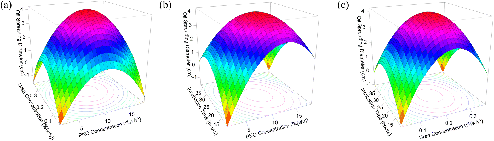 | ||
| Fig. 5 3D contour plots predicting rhamnolipid production as the function of (a) PKO and urea concentration, (b) PKO concentration and incubation time, and (c) urea concentration and incubation time. | ||
The interaction between PKO and urea concentration (see Fig. 4a) gives the darker area (orange part), meaning that the optimum rhamnolipid production is very near to 10% (v/v) of PKO concentration and 0.2% (w/v) of urea concentration. The interaction between PKO concentration and incubation time (see Fig. 4b) also gives the darker area, meaning that the optimum rhamnolipid production is very near to 10% (v/v) of PKO concentration and 22 h of incubation time. Fig. 4c also produces darker area, meaning that the optimum rhamnolipid production is very near to 0.2% (w/v) of urea concentration and 22 h of incubation time. These results indicate that the model (eqn (3)) is good enough to predict the optimum rhamnolipid production.
Similar results were shown for 3D contour plots. 3D contour plots in Fig. 5 look like an umbrella with the optimum conditions on the top of the plot. The interaction between PKO and urea concentration (see Fig. 5a) gives the optimum rhamnolipid production on the top of the 3D contour plot, which is very near to 10% (v/v) of PKO concentration and 0.2% (w/v) of urea concentration. The interaction between PKO concentration and incubation time (see Fig. 5b) also gives the optimum rhamnolipid production on the top of the 3D contour plot, which is very near to 10% (v/v) of PKO concentration and 22 h of incubation time. Fig. 5c also produces an umbrella-like graph describing the optimum rhamnolipid production, which is very near to 0.2% (w/v) of urea concentration and 22 h of incubation time. Therefore, the highest rhamnolipid concentration occurrence was predicted at 22.487 h of incubation time, and in MSM contains 10.821% (v/v) PKO and 0.209% (w/v) urea. We obtained 0.1362 g rhamnolipid from the 1200 mL production medium.
The product was confirmed and proven using FTIR analysis by analyzing the possible functional groups in rhamnolipid. Significant typical peaks for rhamnolipid are O–H vibration peak at wavenumber 3700–3100 cm−1, C–H at 3100–2700 cm−1, ester C![[double bond, length as m-dash]](https://www.rsc.org/images/entities/char_e001.gif) O at ∼1740 cm−1, carboxyl CO at 1707 cm−1, carboxyl O–H at 1421 cm−1, rhamnosyl C–O–C at 1042 cm−1, and fingerprint region of rhamnolipid at 915–450 cm−1.47,48 Table 3 shows many similarities in the significant FTIR spectra peaks of rhamnolipid from P. stutzeri BK-AB12MT and standard rhamnolipid from P. aeruginosa.
O at ∼1740 cm−1, carboxyl CO at 1707 cm−1, carboxyl O–H at 1421 cm−1, rhamnosyl C–O–C at 1042 cm−1, and fingerprint region of rhamnolipid at 915–450 cm−1.47,48 Table 3 shows many similarities in the significant FTIR spectra peaks of rhamnolipid from P. stutzeri BK-AB12MT and standard rhamnolipid from P. aeruginosa.
| Vibration mode | Functional groups | Wavenumber (cm−1) | |
|---|---|---|---|
| Rhamnolipid from P. stutzeri BK-AB12MT | Standard rhamnolipid from P. aeruginosa | ||
| O–H | Hydroxyl | 3453 | 3418 |
| C–H | –CH2 | 2927 | 2930 |
| C–H | –CH3 | 2958 | 2859 |
| CO |
Ester | 1741 | 1726 |
| C–O–C | Rhamnosyl | 1054 | 1057 |
| C–H | –CH (pyranose) | 870 | 889 |
3.3 Synthesis and characterisation of graphene quantum dots (GQDs)
Graphene quantum dots (GQDs) were successfully synthesized and confirmed qualitatively from the solution color at the end of reaction. The color of GQDs solution was yellow under visible light and blue under UV light (see Fig. 6). | ||
| Fig. 6 GQDs solution under (a) visible light and (b) UV light. | ||
The solution was also characterized using UV-Vis spectrophotometer and had shoulders approximately 227 and 350 nm (see Fig. 7). Karimi and Ramezanzadeh reported that GQDs have a maximum wavelength of 227 nm and 360 nm, implying electronic transition of π–π* and n–π* vibration, respectively.49 The electronic transition of π–π* came from the aromatic ring double bond. Meanwhile, the n–π* vibration came from the carbonyl double bond. We also observed strong absorbance extended to 400 nm, indicating mid-gap states in GQDs that lead to blue emission.50 This result was also confirmed by TD-DFT (Time Dependent-Density Functional Theory) calculation result which can predict UV-Vis absorption spectrum theoretically. The TD-DFT calculation was done by using CAM-B3LYP functional and basis set of def2-SVP with CPCM implicit solvation method. The calculated UV-Vis absorption spectrum is shown in Fig. 8, where there are peaks at wavelengths of 229 nm, 355 nm, and 374 nm, which indicates that there are the most electron transitions from HOMO to LUMO + 4 orbitals by 35%, HOMO to LUMO orbitals by 74%, the HOMO to LUMO + 1 orbitals by 46%, respectively. Therefore, we observed blue GQDs solution under UV light Fig. 6b.
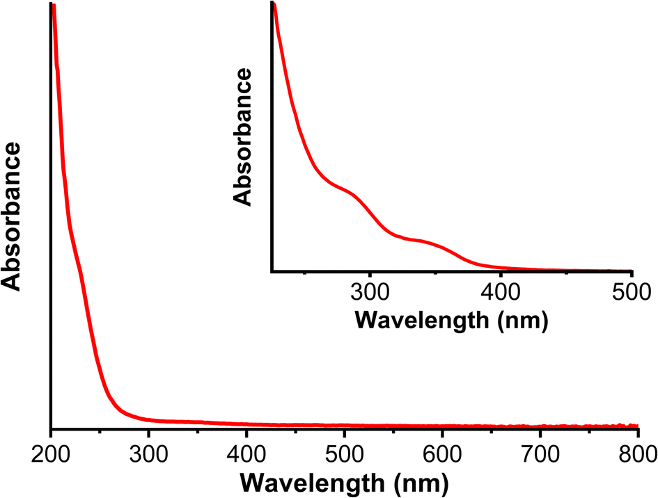 | ||
| Fig. 7 UV-Vis absorption spectra of GQDs. | ||
 | ||
| Fig. 8 UV-Vis absorption spectrum of GQD from TD-DFT calculation. | ||
GQDs were also confirmed using FTIR. The FTIR spectra in Fig. 9 presents the significant peak differences between CA and GQDs. It means that CA had already pyrolyzed and partially carbonized, forming GQDs. Significant peaks typical for GQDs are O–H vibration peak at wavenumber 3400 cm−1, aromatic CC at 1600 cm−1, and carboxyl CO at 1350 cm−1.26
 | ||
| Fig. 9 FTIR spectra of CA and GQDs. | ||
As shown in Table 4, there are many similarities in the significant peaks of GQDs FTIR spectra, and GQDs synthesized by Dong et al.36 and Karimi and Ramezanzadeh.49
Synthesis of GQDs was also confirmed by observing GQDs crystal structure. The structure was analyzed using X-ray diffraction (XRD). The XRD pattern for GQDs shows a broad (002) peak, meaning that the interlayer spacing of GQDs was approximately 0.34 nm (Fig. 10). This result was similar to the XRD pattern for GQDs synthesized by Dong et al.36 The (002) peak shows that CA carbonization produces graphite structures. This peak also suggests that the interlayer spacing of GQDs structure is more compact due to graphene.51
 | ||
| Fig. 10 XRD pattern for GQDs. | ||
The morphology and size of GQDs were analyzed using TEM. The TEM image in Fig. 11 indicates that GQDs mostly agglomerated. Additionally, as shown in Fig. 11, GQDs have an average diameter of 51.4 ± 7.7 nm.
 | ||
| Fig. 11 TEM image of GQDs. | ||
3.4 Synthesis and characterisation of rhamnolipid-functionalized graphene quantum dots (RL-GQDs)
RL-GQDs were successfully synthesized using standard rhamnolipid, that is, RLSTD-GQDs. To verify the RLSTD-GQDs, the sample was analyzed using FTIR spectroscopy (see Fig. 12). Several FTIR peaks s of GQDs and rhamnolipid mentioned in the previous section were observed in RLSTD-GQDs FTIR spectra, such as O–H vibration peak at 3503 cm−1, –CH2 at 2928 cm−1, –CH3 at 2855 cm−1, ester CO at 1740 cm−1, conjugated CC at 1645 cm−1, rhamnosyl C–O–C at 1042 cm−1, and rhamnolipid fingerprint region at 915–450 cm−1.
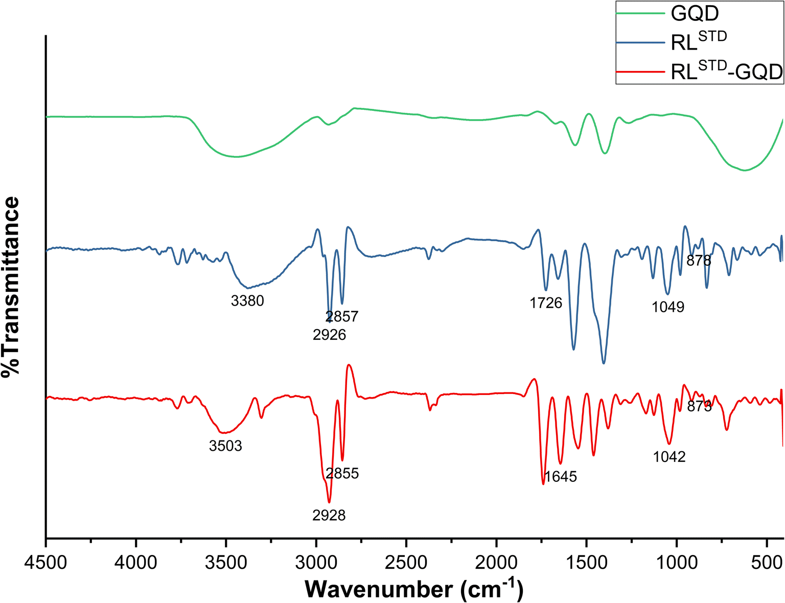 | ||
| Fig. 12 FTIR spectra of GQDs, standard rhamnolipid (RLSTD), and RLSTD-GQDs. | ||
Based on Fig. 12, the carboxylic acid peak of O–H (1400 cm−1) in GQDs disappeared in RLSTD-GQDs. However, the ester CO peak (1740 cm−1) and rhamnolipid fingerprint region emerged. These findings indicated the successful binding of rhamnolipid to GQDs. The addition of ester CO peak indicated the formation of the new ester bond between GQDs and rhamnolipid. Meanwhile, the rhamnolipid fingerprint region indicated the presence of rhamnolipid in RL-GQDs. The disappearance of carboxylic acid O–H peak in RL-GQDs indicated that all carboxylic acid functional groups were esterified with rhamnolipid, forming RL-GQDs. Based on that result, the posible molecular structure of RL-GQDS is depicted in Fig. 18(a).
The successful synthesis of RL-GQDs was also observed using rhamnolipid produced by P. stutzeri BK-AB12MT. Fig. 13 showed similarities between RL-GQDs from standard rhamnolipid and RL-GQDs from P. stutzeri BK-AB12MT rhamnolipid.
 | ||
| Fig. 13 FTIR spectra of RL-GQDs from standard rhamnolipid (RLSTD-GQD) and RL-GQDs from P. stutzeri BK-AB12MT rhamnolipid (RLMT-GQD). | ||
The morphology of RL-GQDs was analysed using TEM. The TEM image in Fig. 14(a) indicates that RL-GQDs formed kinks and folds. GQDs dispersion was also observed (Fig. 14(b)).
 | ||
| Fig. 14 TEM images of RL-GQD. | ||
3.5 Synthesis and characterisation of zinc oxide (ZnO) and titanium dioxide (TiO2)
The most used photocatalysts are ZnO and TiO2. Both photocatalysts are synthesized in our laboratory based on the procedure by He et al.44 and Lin et al.45 The synthesis was successfully done, proven by the XRD pattern.Fig. 15 shows the similar XRD pattern for synthesised ZnO with ZnO synthesized by He et al.44 Fig. 15 also shows similar XRD pattern for synthesized TiO2 with TiO2 synthesized by Liu et al. (anatase phase).52
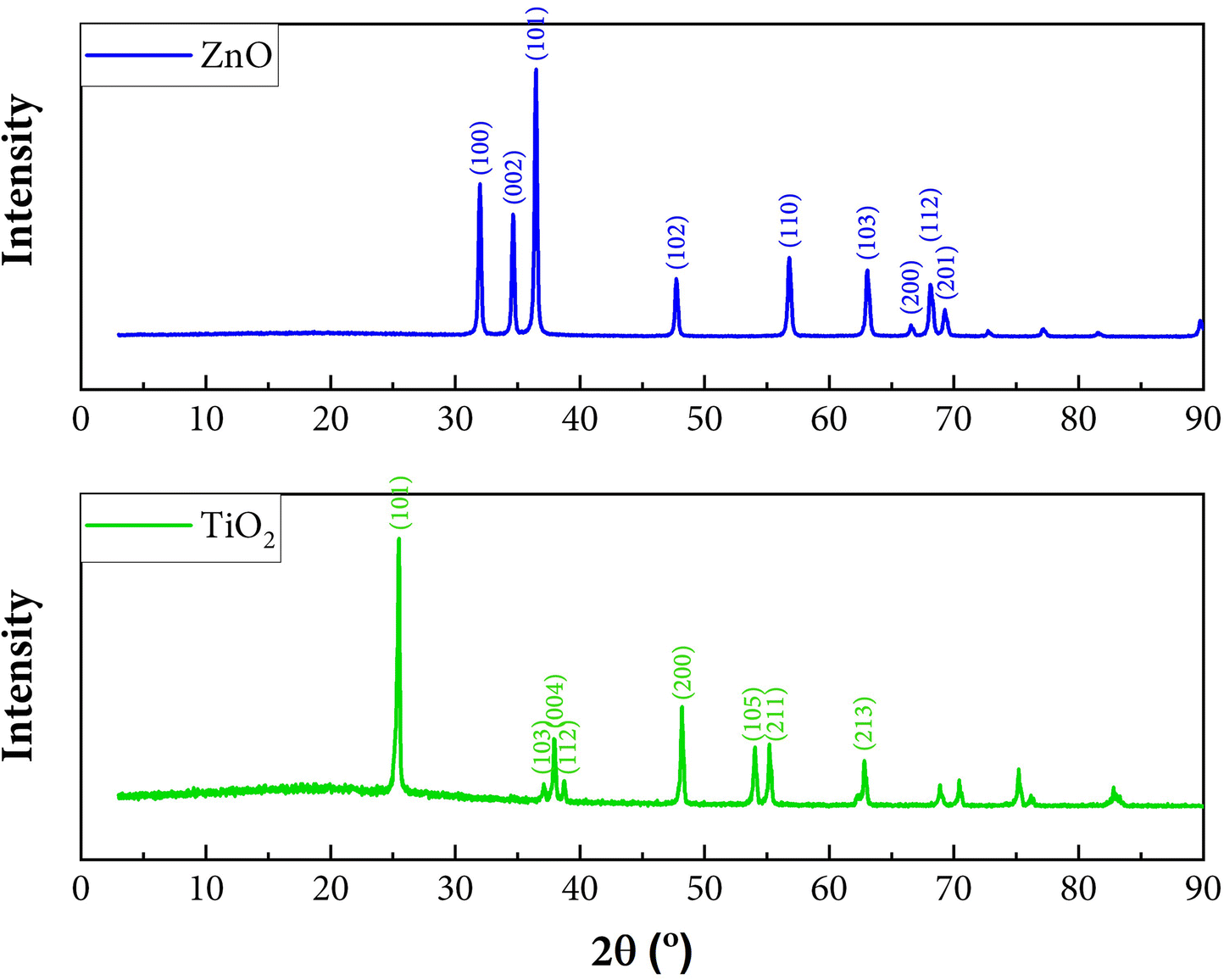 | ||
| Fig. 15 XRD pattern for ZnO and TiO2. | ||
3.6 Photocatalytic degradation reactions
The synthesized RL-GQDs from the previous step were used as a photocatalyst and compared with ZnO and TiO2. After irradiating with visible light for 4 h, we observed the MB degradation from each photocatalysts (see Fig. 16).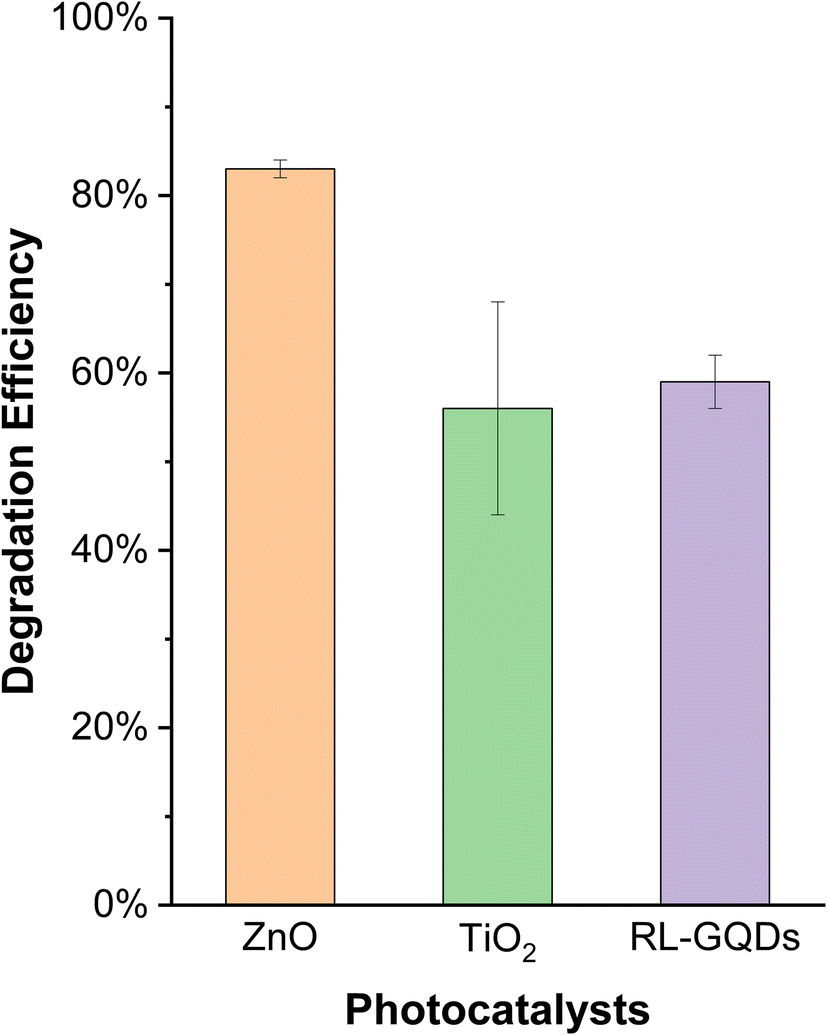 | ||
| Fig. 16 Degradation efficiency of ZnO, TiO2, and RL-GQDs. | ||
Fig. 16 shows that RL-GQDs were a potential photocatalyst. Their degradation efficiency was higher than TiO2. ANOVA and Tukey test were performed, proving no significant difference between RL-GQDs and TiO2's photocatalytic activity. Hence, RL-GQDs were a potential eco-friendly photocatalyst with a degradation efficiency of 59% ± 3%. We also can conclude that RL-GQDs could replace TiO2 as an eco-friendly photocatalyst. This observation could be explained by Kubelka–Munk plot shown in Fig. 17.
 | ||
| Fig. 17 Kubelka–Munk plot of ZnO, TiO2, and RL-GQDs. | ||
Based on Fig. 17, we determined each photocatalysts' bandgap (see Table 5). As shown in Table 5, TiO2 has the most significant bandgap of 3.18 eV, so it is not efficient enough to receive energy. Thus, TiO2 is not a promising visible light photocatalyst. Many researchers dopped TiO2 with other metals or using other photocatalyst such as ZnO to improve it. Meanwhile, RL-GQDs have the smallest bandgap of 0.66 eV. Due to its small value, electron–hole pair recombination will occur. This phenomenon affected the lower photocatalytic activity of RL-GQDs. This result confirms that this photocatalyst is a promising eco-friendly material to replace TiO2.
| Photocatalysts | Bandgap (eV) |
|---|---|
| ZnO | 3.02 |
| TiO2 | 3.18 |
| RL-GQDs | 0.66 |
As seen in Fig. 18(b), photodegradation of MB by photocatalysts. RL-GQDs act as an electron donor which generate electrons by light excitation. Then, the excited electrons transferred from the valence band (VB) to the conduction band (CB), leaving hole (h+). This electron transfer process generates a semi-reduced form of MB. The electron involved in VB's electron reduction produces the radical superoxide anion (O2−˙). Meanwhile, the h+ simultaneously interact with water or OH− to generate the radical OH˙. These radicals facilitate the degradation of MB.27,53 But to validate this proposal, another study must be performed.
 | ||
| Fig. 18 Synthesis (a) and (b) photodegradation schematic of RL-GQDs. | ||
It is still notable that there are many works on using both GQDs composites or functionalized GQDs materials as efficient photocatalysts while the investigation on using rhamnolipid as photocatalyst remains scarce. Herein, we investigated the synthesis of RL-GQDs and their potential as visible-light photocatalysts (Table 6).
| Photocatalysts | Degradation efficiency (%) | Dye | Irradiation time |
|---|---|---|---|
| Pure GQDs (100 mg L−1) | 55 | RhB (10 mg L−1) | 6 h (1000 lm CFL) |
| GOQDs-450coS50 (100 mg L−1) | 92 | RhB (10 mg L−1) | 6 h (22 W, 1000 lm CFL) |
| GQDs/ZnPor (0.3 ppm) | 95 | MB (11.2 mg L−1) | 1 h (150 W Xe lamp) |
| RL@IONPs (400 ppm) | 92.72 | MV (25 ppm) | 170 min (sunlight) |
Pure GQDs synthesized by hydrothermal condensation of pyrene (100 mg L−1) were used to degrade 55% of RhB (10 mg L−1) after 6 h under visible light irradiation (1000 lm of compact fluorescent lamp, CFL).27 Meanwhile, immobilization of GQDs in hydrogels using cross-linkable 3-(triethoxysilyl)propyl-methacrylate (GOQD-A50coS50) (100 mg L−1) could degrade 92% of RhB (10 mg L−1) in the presence of 1 mM H2O2 after 6 h irradiated to visible light (22 W, 1000 lm CFL).54 In another effort, functionalized GQDs by zinc porphyrin (0.3 ppm) were applied to degrade MB (11.2 mg L−1) with a photocatalytic efficiency of 95% in 1 h under visible light irradiation (150 W Xe lamp). Another previous work using rhamnolipid to functionalized Fe3O4 forming RL@IONPs (400 ppm) could degrade methyl violet (25 ppm) with a photocatalytic efficiency of 92.72% attained after 170 min under sunlight and in the presence of 120 ppm sodium dodecyl sulphate (SDS).34
Diverse reaction conditions have been applied on each photocatalyst mentioned above and affected the photocatalytic performance. Furthermore, it needs to be stated the RL-GQDs synthesized in this work could be a promising alternative photocatalyst that is eco-friendlier. However, their photocatalytic performance can be improved by optimizing parameters during photocatalysis, such as light source, pH, photocatalyst dosage, and pollutant concentration.
4. Conclusions
Rhamnolipid production has been enhanced by mutating the P. stutzeri BK-AB12 cells using UV light and optimizing the production conditions using RSM. Rhamnolipid can be produced optimally by irradiating the bacterium cells for 25 min. The optimum rhamnolipid production was obtained using RSM with a PKO concentration of 10.821% (v/v), urea concentration of 0.209% (w/v), and incubation time of 22.487 h. FTIR spectroscopy confirmed the rhamnolipid produced in this study from some functional groups shown in the specific wavenumber. GQDs synthesis was also successfully done from the confirmation of XRD, FTIR, and TEM analysis showing that synthesized GQDs had round morphology and agglomerated. Furthermore, RL-GQDs were successfully synthesized and proved by observing significant peaks of GQDs and rhamnolipid on FTIR spectra. This study proved that synthesized RL-GQDs could be employed as an eco-friendly photocatalyst to replace TiO2 in the MB removal process with a degradation efficiency of 59% ± 3% under visible light irradiation, 3% higher than that with TiO2.Author contributions
S. I. conceived the presented idea. S. I. and F.·F.·H. developed the theory and performed the computations. S. I. and A. L. I. verified the analytical methods. S. I., F.·F. H. and A. L. I. investigate. R. H. supervised the findings of this work. All authors discussed the results and contributed to the final manuscript.Conflicts of interest
There are no conflicts to declare.Acknowledgements
This research was funded by Riset Pengembangan Unggulan ITB 2021.References
- O. J. Hao, H. Kim and P. C. Chiang, Crit. Rev. Environ. Sci. Technol., 2000, 30, 449–505 CrossRef CAS
.
- E. Forgacs, T. Cserháti and G. Oros, Environ. Int., 2004, 30, 953–971 CrossRef CAS PubMed
- F. Zhang, X. Wang, H. Liu, C. Liu, Y. Wan, Y. Long and Z. Cai, Appl. Sci., 2019, 9, 2489 CrossRef CAS
- M. S. Anantha, S. Olivera, C. Hu, B. K. Jayanna, N. Reddy, K. Venkatesh, H. B. Muralidhara and R. Naidu, Environ. Technol. Innovation, 2020, 17, 100612 CrossRef
- M. Humayun, F. Raziq, A. Khan and W. Luo, Green Chem. Lett. Rev., 2018, 11, 86–102 CrossRef CAS
- R. Fagan, D. E. McCormack, D. D. Dionysiou and S. C. Pillai, Mater. Sci. Semicond. Process., 2016, 42, 2–14 CrossRef CAS
- P. Nandi and D. Das, Appl. Surf. Sci., 2019, 465, 546–556 CrossRef CAS
- D. A. Keane, K. G. Mcguigan, P. Fernandez Ibanez, P. Solar, A. Anthony, J. Byrne, K. Da, M. Kg, I. Pf, B. Mi, D. Aj and S. K. Psm, Solar photocatalysis for water disinfection: Materials and reactor design Citation, 2014 Search PubMed
- Z. Mirzaeifard, Z. Shariatinia, M. Jourshabani and S. M. Rezaei Darvishi, Ind. Eng. Chem. Res., 2020, 59, 15894–15911 CrossRef CAS
- M. Khan, M. S. A. Khan, K. K. Borah, Y. Goswami, K. R. Hakeem and I. Chakrabartty, Environ. Adv., 2021, 6, 100128 CrossRef CAS
- Y. Ge, J. P. Schimel and P. A. Holden, Environ. Sci. Technol., 2011, 45, 1659–1664 CrossRef CAS PubMed
- P. Khare, A. Singh, S. Verma, A. Bhati, A. K. Sonker, K. M. Tripathi and S. K. Sonkar, ACS Sustainable Chem. Eng., 2018, 6, 579–589 CrossRef CAS
- M. Shanmugam, A. Alsalme, A. Alghamdi and R. Jayavel, ACS Appl. Mater. Interfaces, 2015, 7, 14905–14911 CrossRef CAS PubMed
- X. Li, R. Shen, S. Ma, X. Chen and J. Xie, Appl. Surf. Sci., 2018, 430, 53–107 CrossRef CAS
- Z. Zhang, T. Zheng, X. Li, J. Xu and H. Zeng, Part. Part. Syst. Charact., 2016, 33, 457–472 CrossRef
- M. Thakur, M. K. Kumawat and R. Srivastava, RSC Adv., 2017, 7, 5251–5261 RSC
- S. Mahalingam, A. Manap, A. Omar, F. W. Low, N. F. Afandi, C. H. Chia and N. A. Rahim, Renewable Sustainable Energy Rev., 2021, 144, 110999 CrossRef CAS
- C. O. Kim, S. W. Hwang, S. Kim, D. H. Shin, S. S. Kang, J. M. Kim, C. W. Jang, J. H. Kim, K. W. Lee, S. H. Choi and E. Hwang, Sci. Rep., 2014, 4, 5603 CrossRef CAS PubMed
- S. Bansal, J. Singh, U. Kumari, I. P. Kaur, R. P. Barnwal, R. Kumar, S. Singh, G. Singh and M. Chatterjee, Int. J. Nanomed., 2019, 14, 809–818 CrossRef PubMed
- P. Dong, B. P. Jiang, W. Q. Liang, Y. Huang, Z. Shi and X. C. Shen, Inorg. Chem. Front., 2017, 4, 712–718 RSC
- X. Zhao, Y. Wu, Y. Wang, H. Wu, Y. Yang, Z. Wang, L. Dai, Y. Shang and A. Cao, Nano Res., 2020, 13, 1044–1052 CrossRef CAS
- P. Yang, J. Su, R. Guo, F. Yao and C. Yuan, Anal. Methods, 2019, 11, 1879–1883 RSC
- D. Iannazzo, A. Pistone, M. Salamò, S. Galvagno, R. Romeo, S. v. Giofré, C. Branca, G. Visalli and A. di Pietro, Int. J. Pharm., 2017, 518, 185–192 CrossRef CAS PubMed
- P. Tian, L. Tang, K. S. Teng and S. P. Lau, Mater. Today Chem., 2018, 10, 221–258 CrossRef CAS
- J. Qian, C. Shen, J. Yan, F. Xi, X. Dong and J. Liu, J. Phys. Chem. C, 2018, 122, 349–358 CrossRef CAS
- S. Kundu and V. K. Pillai, Phys. Sci. Rev., 2020, 5, 20190013 Search PubMed
- A. Ibarbia, H. J. Grande and V. Ruiz, Part. Part. Syst. Charact., 2020, 37(5), 2000061 CrossRef CAS
- Q. Lu, Y. Zhang and S. Liu, J. Mater. Chem. A, 2015, 3, 8552–8558 RSC
- K. A. Tsai and Y. J. Hsu, Appl. Catal., B, 2015, 164, 271–278 CrossRef CAS
- C. X. Guo, Y. Dong, H. bin Yang and C. M. Li, Adv. Energy Mater., 2013, 3, 997–1003 CrossRef CAS
- M. Blesic, V. DIchiarante, R. Milani, M. Linder and P. Metrangolo, in Pure and Applied Chemistry, Walter de Gruyter GmbH, 2018, vol. 90, pp. 305–314 Search PubMed
- G. G. Ying, Environ. Int., 2006, 32, 417–431 CrossRef CAS PubMed
- R. S. Reis, A. G. Pereira, B. C. Neves and D. M. G. Freire, Bioresour. Technol., 2011, 102, 6377–6384 CrossRef CAS PubMed
- S. S. Bhosale, S. S. Rohiwal, L. S. Chaudhary, K. D. Pawar, P. S. Patil and A. P. Tiwari, J. Mater. Sci.: Mater. Electron., 2019, 30, 4590–4598 CrossRef CAS
- R. R. Fazli and R. Hertadi, in IOP Conference Series: Earth and Environmental Science, Institute of Physics Publishing, 2018, vol. 209 Search PubMed
- Y. Dong, J. Shao, C. Chen, H. Li, R. Wang, Y. Chi, X. Lin and G. Chen, Carbon, 2012, 50, 4738–4743 CrossRef CAS
- K. T. Yong and M. T. Swihart, Nanomedicine, 2012, 7, 1641–1643 CrossRef CAS PubMed
- K. Lin and A. Wang, J. Exp. Microbiol. Immunol., 2001, 1, 32–46 Search PubMed
- G. S. El-Housseiny, K. M. Aboshanab, M. M. Aboulwafa and N. A. Hassouna, Indian J. Biotechnol., 2017, 16, 611–619 CAS
- M. Morikawa, Y. Hirata and T. Imanaka, Biochim. Biophys. Acta, 2000, 1488, 211–218 CrossRef CAS PubMed
- D. C. Montgomery, Design and Analysis of Experiments, John Wiley & Sons, Inc., United States, 8th edn, 2013 Search PubMed
- R. v. Lenth, J. Stat. Softw., 2012, 32, 1–17 Search PubMed
- Z. Wu, H. Zhong, X. Yuan, H. Wang, L. Wang, X. Chen, G. Zeng and Y. Wu, Water Res., 2014, 67, 330–344 CrossRef CAS PubMed
- L. He, Z. Tong, Z. Wang, M. Chen, N. Huang and W. Zhang, J. Colloid Interface Sci., 2018, 509, 448–456 CrossRef CAS PubMed
- X. Lin, S. Li, J. Jung, W. Ma, L. Li, X. Ren, Y. Sun and T. S. Huang, RSC Adv., 2019, 9, 23071–23080 RSC
- L. Zhang, J. E. Pemberton and R. M. Maier, Process Biochem., 2014, 49, 989–995 CrossRef CAS
- W. A. Eraqi, A. S. Yassin, A. E. Ali and M. A. Amin, Biotechnol. Res. Int., 2016, 2016, 1–9 CrossRef PubMed
- J. Kiefer, M. N. Radzuan and J. Winterburn, Appl. Sci., 2017, 7, 533 CrossRef
- B. Karimi and B. Ramezanzadeh, J. Colloid Interface Sci., 2017, 493, 62–76 CrossRef CAS PubMed
- Y. Liu and D. Y. Kim, Chem. Commun., 2015, 51, 4176–4179 RSC
- M. Hasanzadeh, A. Karimzadeh, S. Sadeghi, A. Mokhtarzadeh, N. Shadjou and A. Jouyban, J. Mater. Sci.: Mater. Electron., 2016, 27, 6488–6495 CrossRef CAS
- Y. Liu, X. Zhu, D. Yuan, W. Wang and L. Gao, Sci. Rep., 2020, 10, 12444 CrossRef CAS PubMed
- Q. Lu, Y. Zhang and S. Liu, J. Mater. Chem. A, 2015, 3, 8552–8558 RSC
- A. Ibarbia, L. Sánchez-Abella, L. Lezama, H. J. Grande and V. Ruiz, Appl. Surf. Sci., 2020, 527, 146937 CrossRef CAS
Footnote |
| † Electronic supplementary information (ESI) available. See DOI: https://doi.org/10.1039/d2ra05967c |
| This journal is © The Royal Society of Chemistry 2023 |