 Open Access Article
Bi2O3 modified TiO2 nanotube arrays and their application towards unsymmetrical dimethylhydrazine degradation in wastewater by electroassisted photocatalysis†
YiZhi Zeng a,
Feng Zhou
 *a and
Yuan Gaob
aXi'an Research Inst. of Hi-Tech, Xi'an 710025, China. E-mail: 157771601@qq.com
bEngineering Quality Supervision Center, Beijing, 100142, China
First published on 19th January 2023
Abstract
In the present research, the preparation process parameters of TiO2 nanotube arrays (TNAs) prepared by anodic oxidation were systematically studied by the orthogonal experimental method for the first time. Herein, the parameters of nine factors were optimized; the optimal parameters were: the electrolyte was a 0.2 mol L−1 NaF solution with 3% vol H2O at pH 7, the anodic oxidation voltage was 40 V, the electrode spacing was 4 cm and the reaction was carried out for 60 minutes. The physicochemical properties of the materials were characterized by SEM, XRD, EDS, UV-vis, and PL spectroscopy. By electrodeposition of Bi2O3 modified TNAs, the degradation rate of unsymmetrical dimethylhydrazine (UDMH) wastewater on the TNAs-10 was 89.14% within 10 h, which was 2.69 times that on pure TNAs. A bias potential of +0.3 V (vs. open circuit potential) was applied to the modified TNAs-10. The degradation rate of UDMH was significantly enhanced on the TNAs-10 (bias) process as compared to the TNAs-10 process. The degradation rate of UDMH wastewater on TNAs-10 (bias) exhibited an exponential distribution. UDMH and its toxic by-products FDMH, NDMA were completely degraded after 8 h.
1 Introduction
Environmental pollution and energy shortage have seriously affected human survival and social development. UDMH is widely used as a propellant in aerospace and military fields,1 and a large amount of UDMH wastewater is produced. UDMH and its by-products, such as N-nitrosodimethylamine (NDMA) and formaldehyde dimethyl hydrazone (FDMH), are considered carcinogenic toxins and represent a serious health hazard to the population.2,3 Therefore, the demand for the treatment of UDMH wastewater is requisite. There are many conventional treatment methods for the UDMH wastewater, which can be classified as physical, chemical, and biological methods. Traditional physical techniques such as adsorption by activated carbon, ion exchange and incineration were not appropriate for the treatment of UDMH wastewater due to the regeneration of adsorbents and resins as well as contamination by products of incomplete incineration. Chemical methods, such as H2O2/O3/UV, catalytic oxidation of Cu, Fe, and Co salts combined with H2O2/O3 (i.e., heterogeneous Fenton) are trapped in the need to continue to produce O3, resulting in high energy consumption and high operating costs.4 Liang, et al.5 degraded UDMH by the method of catalytic wet peroxide oxidation (CWPO) with CuO/ZnO/NiO/g-Al2O3, Cu2+ and H2O2. However, it would cause secondary pollution due to the difficulty in recycling metal ions. In addition, hydrogen peroxide was consumed and excess H2O2 need to be removed with MnO2. Biological methods have been developed to treat UDMH-containing wastewater, including plant and microbiological methods. It requires longer reaction time, as a result, could not meet the demand for treating higher concentrations of UDMH in wastewater. Furthermore, these methods are mainly disadvantageous in that they generate NDMA, which is even more toxic than UDMH.5 Recently, a series of new methods were developed for the degradation of UDMH. Smirnov et al.6 studied the transformation mechanism of UDMH by catalytic combustion over Pt/SiO2 catalyst at different temperatures, the UDMH decomposed by two-step oxidation. The residue consists mostly of condensed C![[triple bond, length as m-dash]](https://www.rsc.org/images/entities/char_e002.gif) N nitrile groups which totally block the platinum surface. However, it is not suitable for the purification of UDMH wastewater.
N nitrile groups which totally block the platinum surface. However, it is not suitable for the purification of UDMH wastewater.
As an energy-efficient, green, and environmentally friendly technology, photocatalysis has a good application prospect in environmental pollution eliminated.7 It is well known that titanium oxide (TiO2) has been widely used due to its non-selectivity during the photocatalytic degradation of organic compounds, photocatalytic hydrogen production, organic synthesis, medical and health care, architectural coatings, and so on.8 Nano TiO2 is favored in practical research because of its good photoelectric properties due to its quantum yield. However, TiO2 can only be activated under UV light due to its wide band gap (Eg, 3.0–3.2 eV). To overcome the drawbacks, there has been several strategies to modify TiO2 including chemical (metal, non-metal doping and co-doping, coupled semiconductors) and morphological (higher surface area/porosity) techniques. Coupling TiO2 with other narrow band gap semiconductors with matching band potentials to form heterojunction structures has been considered to improve its efficiency. The composite heterojunction system can be excited by visible light irradiation and can induce the efficient separation of photogenic e−/h+. A variety of composite materials have been reported, such as CdS/TiO2,9 Fe2O3/TiO2,10 ZnO/TiO2,11 g-C3N4/TiO2,12 and so on. In addition, the support with high specific surface area is also one of the effective ways to improve the photocatalytic activity. Huang et al.13 synthesized TiO2/SBA-15 catalysts with SBA-15 mesoporous silica as photocatalyst support, and optimized the photocatalytic removal efficiency of UDMH by adjusting the Si/Ti ratio. However, powdered TiO2 is difficult to recycle for the next application and it would form secondary pollution. Therefore, this study of immobilized supported TiO2 is of great significance for practical applications.
There are many immobilization technologies of TiO2, which can be divided into physical deposition and chemical combination according to the way of binding with the substrate. Physical deposition type, such as dip-coating method,14 electrospinning.15 However, there was the problem of insufficient adhesion between catalyst and support. Chemical binding type, such as thermal spraying,16 magnetron sputtering,17 atomic layer deposition,18 pulsed laser deposition,19 micro-arc oxidation and other methods. There were deficiencies of complex equipment operation, high reaction temperature which was difficult to determine the best activity of anatase crystal. Chemical combination type, there were chemical vapor deposition,20 liquid phase deposition,21 electrophoretic deposition,22 continuous ion layer adsorption reaction23 and hydrothermal method,24 the reaction temperature is relatively lower. Masuda had developed a two-step molding process for fabricating a nanohole array of anodic porous alumina,25 and Pt and Au nanotube arrays were further obtained by electrodeposition. It could overcome the disadvantages of insufficient chemical and thermal stability and low mechanical strength. It has attracted extensive attention because of its rich pore structure, large specific surface area and high bonding strength. Certainly, TiO2 nanotube arrays (TNAs) could be synthesized by anodic oxidation process,26,27 which exhibiting highly photocatalytic oxidation activity and would be widely used in the field of photocatalysis, solar energy conversion, electrochromic.28 Such as degradation of organic pollutants,11 water oxidation, oxygen reduction,24 photoelectrochemical sensor and photo fuel cell.29 The anodic oxidation method is to form a regular tube array structure on the surface of pure metal by in situ current corrosion. Its morphology and photoelectric properties of TNAs were easily affected by composition of electrolyte, applied potential, the time of anodization, calcination temperature and others.30,31 Especially, Das S. et al.32 and Ai et al.33 investigated the effect of temperature on the crystalline phase formation and composition of TNAs. The energetic alignment of the band edges of the rutile and anatase phases in the TNAs was very important to clarify the underlying mechanism and to design the high-performance photoelectrodes. However, there is still a lack of a research showed that various factors have a comprehensive impact on TNAs performance. Herein, the preparation technology of TNAs prepared by the anodic oxidation method and the test method of photoelectric properties were systematically studied for the first time by orthogonal experiment.
Currently, researchers paid more attention to the application of TNAs modification to improve photocatalytic properties.8,34 The common modification methods include semiconductor composite, element doping, morphology control, etc. Because of the unique 6s2 electron of Bi element partially coincides with the O 2p orbital, which is beneficial to reduce the band gap of semiconductor material and respond to visible light.35,36 Therefore, a series of Bi2O3 modified TNAs materials were prepared by electrodeposition method and applied to the degradation of UDMH wastewater. In comparison to the pure photocatalytic degradation of UDMH, a bias potential was applied to improve the separation efficiency of photogenerated carriers and the performance of photocatalysts.
2 Experiment
2.1 Reagents and instruments
UDMH (98%) was provided by the Rocket Force Propellant Analysis Center, NDMA (1000 mg L−1) was purchased from O2si (USA), and FDMH (98%) was purchased from Aladdin Biochemical Technology Co., Ltd. Other reagents were analytically pure, and the experimental water was ultrapure water.UPT-II-20T ultrapure water machine, IT6154 DC power, KB-12B high-temperature furnace, P4000A electrochemical workstation, etc. ECO ion chromatograph (IC), metrosep C4 cation column (4.0 mm × 150 mm), conductivity detector, ultimate 3000 high performance liquid chromatography (HPLC), Acclaim C18 reversed-phase column (4.6 mm × 250 mm × 5 μm), DAD-3000 detector.
2.2 Preparation of TNAs
High-purity titanium sheets (>99.99%) were cut into pieces of 1.5 cm × 4.5 cm, chemically polished with a mixture of 5% wt HNO3 and 0.05% wt HF, and then ultrasonically treated with acetone, ethanol, and deionized water for 15 min, and dried with cold air. Dissolve F/Cl ion solute with water in 320 mL ethylene glycol (EG) in a certain proportion to form an electrolyte, and adjust the appropriate pH value of the solution, set anodic oxidation potential, with titanium as an anode, Pt as the counter electrode, for anodic oxidation film. And then the titanium sheet was take out and treated with ultrasonic oscillation in deionized water, 0.05% wt HF solution for 10–15 s, washed with deionized water, respectively, and dried with cold air. Finally, it was put into a high-temperature furnace, heated to 450–550 °C at a rate of 2 °C min−1, calcined in air atmosphere for 4 h, and cooled with the furnace to obtain the sample TNAs. The nine influencing factors of electrolyte composition, concentration of electrolyte, water content, pH, anodic oxidation potential, distance between electrodes, reaction temperature, reaction time, and calcination temperature, which were named factors A, B, C, D, E, F, G, H and I in order. The nine factors were used to design a 3-level orthogonal test with orthogonal table L27 (311). And the corresponding levels in order were: NaF, NH4F, NH4Cl, 0.1 mol L−1, 0.2 mol L−1, 0.3 mol L−1, 1% vol, 3% vol, 5% vol, 5, 7, 9, 30 V, 40 V, 50 V, 2 cm, 3 cm, 4 cm, 25 °C, 30 °C, 35 °C, 30 min, 60 min, 90 min, 450 °C, 500 °C, 550 °C.2.3 Preparation of TNAs/Bi2O3
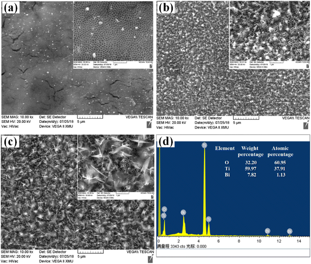
1 mmol Bi(NO3)3 was dissolved in 1 ml of 34% nitric acid solution and then added to 100 ml of ethylene glycol to form a homogeneous electrolyte. The preparation process with the optimized photoelectric properties was obtained, and the modification of TNAs was carried out by electrochemical deposition of Bi(NO3)3. The optimized TNAs as the cathode, Pt as the anode, the potential was 6.0 V and the distance between electrodes was 4 cm, the deposition amount of Bi3+ was controlled by the reaction time (min). The TNAs/Bi2O3 samples were named as TNAs-1, TNAs-5 and TNAs-10 according to the deposition time. Following anneal it at the optimized temperature for 4 h with heating rate of 2 °C min−1 in muffle furnace. The experimental schematic diagram was shown in Fig. S1.†2.4 Photoelectrochemical performance test
A three-electrode test system was constructed with a TNAs sample as the electrode, a Pt plate as the counter electrode, and an Ag/AgCl electrode as the reference electrode. 0.5 mol L−1 Na2SO4 solution as the electrolyte, the optical power of incident light at the working electrode position was 100 mW cm−2, and the photoelectrochemical performance was evaluated with the photocurrent density i (mA cm−2). I–t curves of the samples with different electrodeposition times were tested under repeated changes of light and dark conditions at 0.5 V (vs. ref. Ag/AgCl).2.5 Evaluation of photocatalytic degradation towards UDMH wastewater
CEL-LAB500E 350 W xenon lamp with AM 1.5 filter was used to simulate sunlight as the catalytic light source, and the light power density was set to 100 mW cm−2. The catalyst was applied to 40 ml of 100 mg L−1 UDMH wastewater. Prior to irradiation, dark experiments (adsorption) were carried out for 30 min to reach the adsorption equilibrium of UDMH with the catalyst.The photocatalytic performance of the material was evaluated by degradation efficiency R and reaction kinetics of UDMH. The formula is as follows:
| R = (C0 − Ct)/C0 | (1) |
 | (2) |
2.6 Detection of free radical
According to the process of photocatalytic degradation of organic matter was mainly caused by the direct oxidation of organic pollutants by photogenerated h+/e− pairs, or the reaction with surface adsorbed oxygen (O2), H2O/OH− to generate superoxide radicals (˙O2−), hydroxyl radicals (˙OH) and other active radicals indirectly involved in the reaction. For semiconductor materials, when the conduction band (CB) of the photocatalytic material is more negative than the redox potential of O2/˙O2− (−0.046 eV, vs. NHE), the photogenerated electrons (e−) could react with O2 to form ˙O2−, when the redox potential of VB is more positive than that of H2O/˙OH (2.4 eV, vs. NHE), the photogenerated holes (h+) could oxidize H2O/OH− to form ˙OH.38 Simultaneously, the more O2 on the surface of the catalysts, the more conducive to generation ˙O2−.The trapping agent is added to preferentially interact with the free radicals to form a stable molecular morphology. The mechanism of photocatalytic degradation was analyzed by its effect on UDMH degradation. Herein, 1 mmol L−1 isopropanol (IPA), p-benzoquinone (PBQ), ethylenediamine tetraacetic acid disodium salt (EDTA) and carbon tetrachloride (CTC) were used as quenching agents for ˙OH, ˙O2− h+, and e−, respectively. The effects of active species produced by different materials in the photocatalytic process on the degradation of UDMH wastewater were investigated. The process of UDMH wastewater degradation without a capture agent was used as a blank, and other conditions were consistent with previous ones.
3 Result and discussion
3.1 Optimization of TNAs preparation process
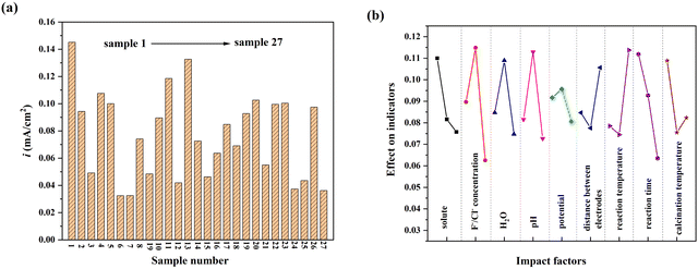
It was found that electrolyte concentration, water content and pH were positively correlated with corrosion. Especially, in alkaline conditions, the nanotube structure was almost invisible on the surface of the material. The corrosion process is relatively stable under neutral conditions, and the morphology is easier to control. The anodic oxidation potential, distance between electrodes and reaction temperature mainly affected the degree of corrosion and the formation rate of nanotubes. The reaction time mainly affected the length and pore size of nanotubes. Calcination temperature mainly affects the crystal structure of TiO2, the main crystal form is anatase from 450 °C to 550 °C.
The optimal process conditions were as follows: the electrolyte was 0.2 mol L−1 NaF solution, the water content was 3% vol, pH = 7, the anodic oxidation potential was 40 V, distance between electrodes was 4 cm, the reaction time was 90 min, and following 450 °C calcination annealing. It can be seen from the range analysis that the influence order of 9 factors on the photocurrent density of TNAs was: anodic oxidation potential < distance between electrodes < calcination temperature < electrolyte solute < water content of electrolyte < anodic oxidation temperature < pH < anodic oxidation time < solute concentration.
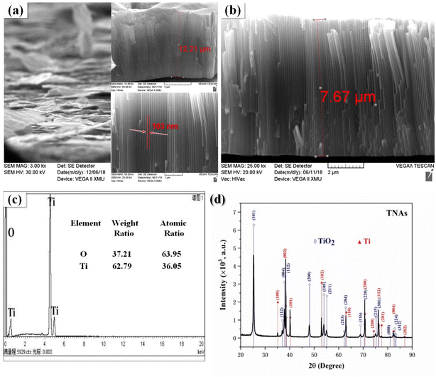
According to the experimental results, the morphology and structure of the orthogonal optimization results are shown in Fig. 2(a). The nanotube length and diameter of the TNAs nanotubes were 12.21 μm, 103 nm, respectively. However, due to the instability of the mechanical structure caused by the long nanotube, it was easy to shed due to external force. Anodic oxidation time is the main reason for the growth of nanotubes, therefore, adjusted the anodic oxidation time to the second level of 60 min. After re-optimization of the sample nanotube length dropped to 7.67 μm, the film and the substrate binding degree increased significantly, and the diameter change was not obvious, as shown in Fig. 2(b). Fig. 2(c) is EDS spectrum of the re-optimized TNAs, which contained Ti and O elements. Fig. 2(d) is the XRD spectrum. It can be observed that the more obvious diffraction peaks of 25.26°, 37.78°, and 48.02° were (101), (004) and (200) crystal plane diffraction peaks of anatase TiO2 (PDF # 73-1764). While the diffraction peaks of 35.06°, 40.25°, and 52.96° were the (100), (101) and (102) crystal plane characteristic diffraction peaks of Ti (PDF # 89-5009). Furthermore, there were overlapping diffraction peaks of TiO2 and Ti at 38.4°, 62.86°, 70.82° and 76.12°, respectively.
3.2 Modification of TNAs by Bi2O3
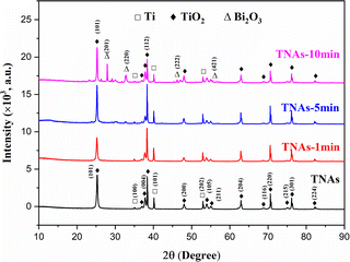
XRD characterization results showed that the crystal parameters of TNAs did not change significantly after Bi2O3 loading modification, as shown in Fig. 4. The diffraction peaks at 35.17°, 40.25° and 53.09° correspond to the (100), (101) and (102) planes of Ti substrate, respectively. 25.37°, 37.05°, 37.91°, 38.67°, 48.16°, 54.05°, 55.20°, 62.87° and 75.28° correspond to the (101), (103), (004), (112), (200), (105), (211), (204) and (215) planes of TiO2 respectively. Different from TNAs and TNAs-1, TNAs-5 showed weak diffraction peaks at 27.9°, 32.84° and 46.18°, while TNAs-10 shows obvious diffraction peaks, which belonged to (201), (220), and (222) planes of Bi2O3, respectively. This showed thatTiO2 on the TNAs substrate was mainly anatase, and composite Bi2O3 was obtained by electrodeposition on its surface.
A typical XPS survey scan for TNAs and TNAs-10 to investigate the chemical valence states of surface elements of this sample, as shown in Fig. S3.† The full spectra showed that TNAs mainly contains Ti, O and C elements (Fig. S3a†), and TNAs-10 was composed of Ti, Bi and O elements (Fig. S3b†), indicating that the Bi-contained species have been introduced into the TNAs composite. It is noted that the C element is originated from the contaminants during the testing process (Fig. S3c†). In Fig. S3d,† the binding energies of O 1s located at 528.3 and 530.5 eV are assigned to lattice oxygen (O2− of Ti–O/Bi–O bond) and surface hydroxyl oxygen (OH−). As displayed in Fig. S3e,† the double peaks with binding energies at 457.3 eV and 463.0 eV on the pure TiO2 correspond to Ti 2p3/2 and Ti 2p1/2 in the form of Ti4+.39 It is noted that a is enhanced and broadened peak can be observed on TNAs-10 min at 464.8 eV which belonged to the overlapping peak of Bi 4d and Ti 2p1/2. The Bi 4f7/2 and Bi 4f5/2 doublet core peaks are observed at 157.8 eV and 163.1 eV (Fig. S3f†), indicating that Bi was existed in the form of Bi3+.35
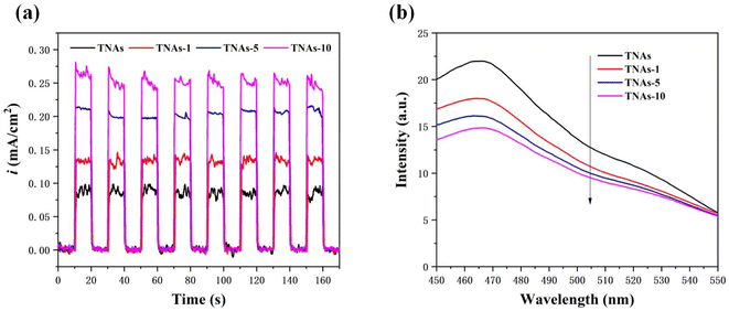 | ||
| Fig. 6 Electrical tests on catalyst samples. (a) Photocurrent densities with the potential of +0.5 V (vs. ref. Ag/AgCl), (b) PL spectrum. | ||
To further reveal the e−/h+ recombination in the samples, the PL spectrum was obtained, and the results were shown in Fig. 6b. The PL emission spectra were measured at an excitation wavelength of 350 nm. The higher the recombination rate, the stronger the fluorescence emission. The fluorescence emission peak intensity of the samples at approximately 465 nm gradually decreased with the increase of Bi2O3 loading, indicating that the modification of Bi2O3 was helpful to reduce the recombination probability of photogenerated carriers and improve the quantum efficiency of the material.
3.3 Photocatalytic performance
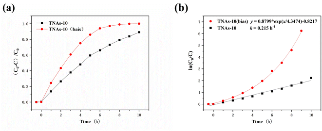
The bias potential significantly improved the degradation efficiency of UDMH wastewater, as shown in Fig. 8. The degradation rate of UDMH on TNAs-10 (bias) was 94.03% in 6 h, and UDMH was completely degraded in about 8 h. It performed better than TNAs-10 with the rate of 89.14% (10 h), as shown in Fig. 8a. Evaluating by pseudo-first-order kinetic module, the degradation rate constant of UDMH wastewater on TNAs-10 was 0.215 h−1, and the degradation rate of UDMH wastewater on TNAs-10 (bias) was exponentially distributed, as shown in Fig. 8b. Thus, the bias potential played an important role in improving the photocatalytic activity.
In addition, the higher generation of FDMH than NDMA was due to the priority of FDMH generation is higher in UDMH degradation process.40. Finally, FDMH and NDMA were completely degraded, indicating that both TNAs-10 and TNAs-10 (bias) could realize non-toxic treatment of UDMH.
3.4 Mechanism of photocatalytic degradation
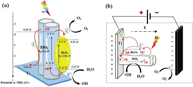
In the presence of visible-light radiation, only Bi2O3 can be excited to generate h+/e− pairs. The e− in the VB of Bi2O3 was excited to the CB, then further promoted by the built-internal electric field and easily transferred to that of TiO2, and reacts with adsorbed oxygen (O2) to form ˙O2−. While the generated h+ remain in the VB of Bi2O3. As a result, the photogenerated h+/e− can be separated effectively, leading to the lifetime of the charge carriers can be effectively prolonged. Some of the photogenerated h+ retained in the VB reacted with H2O in situ to form ˙OH, and the others participated in the degradation of UDMH. It can be seen from the free radical capture experiment that the good conductivity of the Ti substrate enhanced the transfer of e−, result in producing more ˙O2− to participate in the photocatalytic degradation of UDMH. The main active species are still h+ and ˙OH.
Interestingly, when the bias potential is applied, the degradation of UDMH by TNAs-10 (bias), ˙OH is significantly increased. This probably occurred because the anode can also produce h+ to react with H2O to form ˙OH with the action of an applied electric field. When the photocatalytic electrode is excited by light, the external electrostatic field accelerated the separation of photogenerated carriers, and the photogenerated e− flowed along the external circuit to the cathode. Meanwhile, it reacted with the adsorbed oxygen (O2) to form ˙O2− and further to degrade UDMH. However, it would be limited by the small amount of oxygen in the water environment. The photoanode material retained a large amount of h+, which directly oxidizes UDMH or reacts with H2O to generate ˙OH, as shown in Fig. 9(b).
4 Conclusion
A series of TNAs film with anatase structures were fabricated via electrochemical anodization of high purity Ti foil. The nine factors affecting anodic oxidation were optimized by orthogonal experiment. TNAs were modified by electrodeposition of Bi2O3, and the degradation effect of UDMH wastewater was improved by the bias voltage. The main conclusions are as follows:(1) The influence sequence of 9 factors on the photocurrent density of TNAs was as follows: anodic oxidation potential < distance between electrodes < calcination temperature < electrolyte solute < water content of electrolyte < anodic oxidation temperature < pH < anodic oxidation time < solute concentration. Optimal condition parameters were: 0.2 mol L−1 NaF, 3% vol H2O, electrolyte with pH of 7, oxidation voltage of 40 V, electrode spacing of 4 cm, reaction for 60 min at 25 °C water bath.
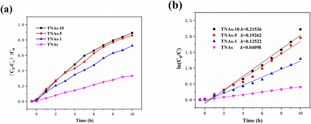
(2) Bi2O3 modified TNAs films were obtained by electrodeposition. The degradation of UDMH in different TNAs/Bi2O3–based processes were evaluated and compared. The degradation followed the pseudo-first-order reaction kinetics model. The degradation rate of UDMH wastewater by TNAs-10 within 10 h was 89.14%, which was 2.69 times of that on the pure TNAs. The reaction rate constant was 0.215 h−1.
(3) A bias potential of +0.3 V (vs. open circuit potential) was applied to the TNAs-10. The degradation rate of UDMH was significantly enhanced on the TNAs-10 (bias) process as compared to the TNAs-10 process. The degradation rate of UDMH wastewater on TNAs-10 (bias) exhibited an exponential distribution. The bias potential plays played an important role in promoting the photocatalytic degradation activity. UDMH and the toxic by-products FDMH, NDMA were completely degraded in 8 h. The results presented herein will provide innovative directions, valuable information and reference for effective removal of UDMH in water.
Prime novelty statement
Nine factors affecting anodic oxidation have been systematically optimised and results obtained using orthogonal experiments. The influence sequence of 9 factors on the photocurrent density of TNAs was as follows: anodic oxidation potential < distance between electrodes < calcination temperature < electrolyte solute < water content of electrolyte < anodic oxidation temperature < pH < anodic oxidation time < solute concentration. For the first time, bias potential photocatalysis was adopted, which improved the separation efficiency of photogenerated electron–hole pairs and the degradation efficiency of UDMH wastewater. The results provide a promising way for preparation of catalyst and degradation of UDMH.Conflicts of interest
There are no conflicts to declare.References
- F. Chen, F. Wang and Q. Li, et al., Effect of support (Degussa P25 TiO2, anatase TiO2, γ-Al2O3, and AlOOH) of Pt-based catalysts on the formaldehyde oxidation at room temperature, Catal. Commun., 2017, 99, 39–42 CrossRef CAS.
- A. L. Milyushkin, K. P. Birin and D. D. Matyushin, et al., Isomeric derivatives of triazoles as new toxic decomposition products of 1,1-dimethylhydrazine, Chemosphere, 2019, 217, 95–99 CrossRef CAS PubMed.
- C. Hu, Y. Zhang and Y. Zhou, et al., Unsymmetrical dimethylhydrazine and related compounds in the environment: recent updates on pretreatment, analysis, and removal techniques, J. Hazard. Mater., 2022, 432, 128708 CrossRef CAS PubMed.
- F. Zhou and X. Ren, Reversible photochromic photocatalyst Bi2O3/TiO2/Al2O3 with enhanced visible photoactivity: application toward UDMH degradation in wastewater, J. Environ. Sci. Health, Part A: Toxic/Hazard. Subst. Environ. Eng., 2020, 55(3), 239–255 CrossRef CAS PubMed.
- M. Liang, W. Li and Q. Qi, et al., Catalyst for the degradation of 1,1-dimethylhydrazine and its by-product n-nitrosodimethylamine in propellant wastewater, RSC Adv., 2016, 6(7), 5677–5687 RSC.
- A. V. Smirnov, P. A. Kots and M. A. Panteleyev, et al., Mechanistic study of 1,1-dimethylhydrazine transformation over Pt/SiO2 catalyst, RSC Adv., 2018, 8(64), 36970–36979 RSC.
- K. Qi, B. Cheng and J. Yu, et al., A review on TiO2-based z-scheme photocatalysts, Chin. J. Catal., 2017, 38(12), 1936–1955 CrossRef CAS.
- A. Kumar, P. Choudhary and A. Kumar, et al., Recent advances in plasmonic photocatalysis based on TiO2 and noble metal nanoparticles for energy conversion, environmental remediation, and organic synthesis, Small, 2022, 18(1), 2101638 CrossRef CAS.
- X. Gao, X. Liu and X. Wang, et al., Photodegradation of unsymmetrical dimethylhydrazine by TiO2 nanorod arrays decorated with Cds nanoparticles under visible light, Nanoscale Res. Lett., 2016, 11(1), 496 CrossRef PubMed.
- M. M. Mohamed, W. A. Bayoumy and M. E. Goher, et al., Optimization of α-Fe2O3@Fe3O4 incorporated N-TiO2 as super effective photocatalysts under visible light irradiation, Appl. Surf. Sci., 2017, 412, 668–682 CrossRef CAS.
- J. You, L. Zhang and L. He, et al., Photocatalytic degradation of methyl orange on ZnO–TiO2/SO42− heterojunction composites, Opt. Mater., 2022, 131, 112737 CrossRef CAS.
- J. Liu, B. Cheng and J. Yu, A new understanding of the photocatalytic mechanism of the direct z-scheme g-C3N4/TiO2 heterostructure, Phys. Chem. Chem. Phys., 2016, 18(45), 31175–31183 RSC.
- Y. Huang, Y. Jia and R. Hou, et al., Photocatalytic degradation of unsymmetrical dimethylhydrazine on TiO2/SBA-15 under 185/254 nm vacuum-ultraviolet, RSC Adv., 2021, 11(39), 24172–24182 RSC.
- H. K. Hakki, S. Allahyari and N. Rahemi, et al., Surface properties, adherence, and photocatalytic activity of sol–gel dip-coated TiO2-ZnO films on glass plates, C. R. Chim., 2019, 22(5), 393–405 CrossRef CAS.
- T. Istirohah, S. Wihdatul Himmah and M. Diantoro, Fabrication of aligned PAN/TiO2 fiber using electric electrospinning (ees), Mater. Today: Proc., 2019, 13, 211–216 CAS.
- I. D. Utu, G. Marginean and I. Hulka, et al., Properties of the thermally sprayed Al2O3-TiO2 coatings deposited on titanium substrate, Int. J. Refract. Met. Hard Mater., 2015, 51, 118–123 CrossRef CAS.
- J. A. P. Nuñez, H. S. Salapare and M. M. S. Villamayor, et al., Antibacterial efficiency of magnetron sputtered TiO2 on poly(methyl methacrylate), Surf. Interfaces, 2017, 8, 28–35 CrossRef.
- F. Dvorak, R. Zazpe and M. Krbal, et al., One-dimensional anodic TiO2 nanotubes coated by atomic layer deposition: towards advanced applications, Appl. Mater. Today, 2019, 14, 1–20 CrossRef.
- I. Olvera-Rodríguez, R. Hernández and A. Medel, et al., TiO2/Au/TiO2 multilayer thin-film photoanodes synthesized by pulsed laser deposition for photoelectrochemical degradation of organic pollutants, Sep. Purif. Technol., 2019, 224, 189–198 CrossRef.
- L. Weihao, C. Shengnan and W. Jianxun, et al., Study on structural, optical and hydrophilic properties of FTO/TiO2 tandem thin film prepared by aerosol-assisted chemical vapor deposition method, Surf. Coat. Technol., 2019, 358, 715–720 CrossRef.
- C. Xu, Y. Zhong and Y. Zheng, et al., Micromixing-assisted preparation of TiO2 films from ammonium hexafluorotitanate and urea by liquid phase deposition based on simulation of mixing process in t-shaped micromixer, Ceram. Int., 2019, 45(9), 11325–11334 CrossRef CAS.
- S. Obregón, G. Amor and A. Vázquez, Electrophoretic deposition of photocatalytic materials, Adv. Colloid Interface Sci., 2019, 269, 236–255 CrossRef PubMed.
- I. Jellal, K. Nouneh and H. Toura, et al., Enhanced photocatalytic activity of supported Cu-doped ZnO nanostructures prepared by silar method, Opt. Mater., 2021, 111, 110669 CrossRef CAS.
- B. Zhang, L. He and T. Yao, et al., Simultaneous photoelectrocatalytic water oxidation and oxygen reduction for solar electricity production in alkaline solution, ChemSusChem, 2019, 12(5), 1026–1032 CrossRef CAS PubMed.
- H. Masuda and K. Fukuda, Ordered metal nanohole arrays made by a two-step replication of honeycomb structures of anodic alumina, Science, 1995, 268(5216), 1466–1468 CrossRef CAS.
- X. Chen and S. S. Mao, Titanium dioxide nanomaterials: synthesis, properties, modifications, and applications, Chem. Rev., 2007, 107(7), 2891–2959 CrossRef CAS PubMed.
- D. Gong, C. A. Grimes and O. K. Varghese, et al., Titanium oxide nanotube arrays prepared by anodic oxidation, J. Mater. Res., 2001, 16(12), 3331–3334 CrossRef CAS.
- Y. Wei, B. Han and Z. Dong, et al., Phosphomolybdic acid-modified highly organized TiO2 nanotube arrays with rapid photochromic performance, J. Mater. Sci. Technol., 2019, 35(9), 1951–1958 CrossRef CAS.
- L. He, Q. Liu and S. Zhang, et al., High sensitivity of TiO2 nanorod array electrode for photoelectrochemical glucose sensor and its photo fuel cell application, Electrochem. Commun., 2018, 94, 18–22 CrossRef CAS.
- Y. Zhao, L. Zhu and Y. Yu, et al., Facile one-pot preparation of Ti3+, N co-doping TiO2 nanotube arrays and enhanced photodegradation activities by tuning tube lengths and diameters, Catal. Today, 2019, 563–572 Search PubMed.
- J. M. Macak, H. Tsuchiya and A. Ghicov, et al., TiO2 nanotubes: self-organized electrochemical formation, properties and applications, Curr. Opin. Solid State Mater. Sci., 2007, 11(1–2), 3–18 CrossRef CAS.
- S. Das, R. Zazpe and J. Prikryl, et al., Influence of annealing temperatures on the properties of low aspect-ratio TiO2 nanotube layers, Electrochim. Acta, 2016, 213, 452–459 CrossRef CAS.
- C. Ai, P. Xie and X. Zhang, et al., Explaining the enhanced photoelectrochemical behavior of highly ordered TiO2 nanotube arrays: anatase/rutile phase junction, ACS Sustainable Chem. Eng., 2019, 7(5), 5274–5282 CrossRef CAS.
- H. Fan, S. Zhang and X. Zhu, Nitrided TiO2 nanoparticles/nanotube arrays for better electrochemical properties, Chem. Phys. Lett., 2019, 730, 340–344 CrossRef CAS.
- Z. Liu, J. Tian and C. Yu, et al., Solvothermal fabrication of Bi2MoO6 nanocrystals with tunable oxygen vacancies and excellent photocatalytic oxidation performance in quinoline production and antibiotics degradation, Chin. J. Catal., 2022, 43(2), 472–484 CrossRef CAS.
- W. Fang and W. Shangguan, A review on bismuth-based composite oxides for photocatalytic hydrogen generation, Int. J. Hydrogen Energy, 2019, 44(2), 895–912 CrossRef CAS.
- F. Zhou, X. Ren and S. Du, Direct evaluation of unsymmetrical dimethylhydrazine with wide concentration range in wastewater by ion chromatography, Chromatographia, 2020, 83(1), 107–113 CrossRef CAS.
- Q. Hao, C. Xie and Y. Huang, et al., Accelerated separation of photogenerated charge carriers and enhanced photocatalytic performance of g-C3N4 by Bi2S3 nanoparticles, Chin. J. Catal., 2020, 41(2), 249–258 CrossRef CAS.
- X. Lin, M. Sun and Y. Yao, et al., In situ construction of N/Ti3+ co-doped tri-phasic TiO2 layer on TiO2 nanotube arrays to improve photoelectrochemical performance, Electrochim. Acta, 2018, 291, 319–327 CrossRef CAS.
- D. Huang, X. Liu and X. Wang, et al., The competitive formation mechanism of n-nitrosodimethylamine and formaldehyde dimethylhydrazone from 1,1-dimethylhydrazine during ozonation in air: a combined theoretical and experimental study, Chem. Phys., 2019, 522, 220–227 CrossRef CAS.
- Y. Huang, Y. Wei and J. Wang, et al., Controllable fabrication of Bi2O3/TiO2 heterojunction with excellent visible-light responsive photocatalytic performance, Appl. Surf. Sci., 2017, 423, 119–130 CrossRef CAS.
- D. Xu, Y. Hai and X. Zhang, et al., Bi2O3 cocatalyst improving photocatalytic hydrogen evolution performance of TiO2, Appl. Surf. Sci., 2017, 400, 530–536 CrossRef CAS.
Footnote |
| † Electronic supplementary information (ESI) available. See DOI: https://doi.org/10.1039/d2ra05953c |
| This journal is © The Royal Society of Chemistry 2023 |

