DOI:
10.1039/D2RA05383G
(Paper)
RSC Adv., 2023,
13, 6389-6395
A portable acetylcholinesterase-based electrochemical sensor for field detection of organophosphorus†
Received
27th August 2022
, Accepted 23rd January 2023
First published on 3rd March 2023
Abstract
A portable acetylcholinesterase (AChE)-based electrochemical sensor based on a screen-printed carbon electrode (SPCE) and a miniature potentiostat was constructed for the rapid field detection of organophosphorus pesticides (OPs). Graphene (GR) and gold nanoparticles (AuNPs) were successively introduced onto SPCE for surface modification. Due to the synergistic effect of the two nanomaterials, the signal of the sensor has a significant enhancement. Take isocarbophos (ICP) as a model for chemical warfare agents (CAWs) and Ops; the SPCE/GR/AuNPs/AChE/Nafion sensor shows a wider linear range (0.1–2000 μg L−1), and a lower limit of detection (0.012 μg L−1) than SPCE/AChE/Nafion and SPCE/GR/AChE/Nafion sensors. Tests in actual fruit and tap water samples also yielded satisfactory results. Therefore, the proposed method can be used as a simple and cost-effective strategy for construction of portable electrochemical sensors for OP field detection.
1 Introduction
Despite being restricted by the Chemical Weapons Convention, some unscrupulous organizations are still secretly developing or using chemical warfare agents (CWAs).1–3 With the frequent international local conflicts and intensified regional ethnic conflicts in recent years, the possibility of casualties caused by CWAs has greatly increased.4–6 The most widely used and most toxic CWAs are nerve agents, which belong to the organic phosphonate compounds. They have a strong inhibitory effect on the activity of acetylcholinesterase (AChE), which can cause the accumulation of acetylcholine (ACh) in the body, resulting in serious disorders of the central and peripheral nerve functions.7–9 Considering the enormous threat of nerve agents to national security and battlefield security, there is an urgent need to develop a rapid, reliable, cost-effective, and portable field detection strategy to provide safety early warning of nerve agent levels in the environment to ensure timely medical treatment. Less toxic organophosphorus pesticides (OPs) are usually chosen as alternatives during research because they are similar in structure and mechanism of action to neurotoxic agents.10–12 In addition, OPs are prevalent in modern agricultural production, and excessive use can cause great harm to the environment and human body.13–17 Therefore, in addition to battlefield and national security applications, such detection researches provide a tremendous help in protecting civilians from OPs harm.
The current popular strategies for detecting OPs are represented by electrochemical biosensors.18 Compared with traditional instruments (gas chromatography mass spectrometry,19,20 high performance liquid chromatography21 spectrophotometry,22 capillary electrophoresis23), electrochemical biosensors are fast in analysis and do not require complex processing, special expertise or expensive equipment. As more and more nanomaterials with excellent properties are synthesized and introduced into the construction of electrochemical sensors, such as metal nanoparticles,24–26 carbon-based nanomaterials,27–29 composite materials30–36 etc. Due to their large specific surface area, high reactivity, strong adsorption capacity, good biocompatibility and electrical conductivity, they have been used to stabilize and improve the biosensing interface and amplify the detection signal, which improved the detection performance of the sensors to a new level.37 Nevertheless, many studies still rely on laboratory-based environments that are difficult to set up in the field. Therefore, portable electrochemical sensors are convenient and suitable for practical needs. The use of low-power portable potentiostat and low-cost, mass-producible, small screen-printed electrodes can be considered an effective strategy for rapid and lots of detection of sensors in the field38 our group already has some experience in ICP detection.39 In this study, we used a portable sensing platform based on SPCE and a small constant potential meter to construct an electrochemical sensor for AChE from the perspective of improving the practical application capability. On SPCE surfaces, we successively used GR and AuNPs for drop coating modification. GR has good electrical conductivity and large specific surface area, which can accelerate the electron transfer on the surface of SPCE. AuNPs also have good electrical conductivity and excellent biocompatibility. The small particle size of AuNPs facilitates the penetration into the active center of AChE, which will better maintain the activity of AChE on the electrode and accelerate its catalytic substrate hydrolysis reaction. Using the synergistic effect of the two, a double signal amplification effect was obtained. Finally, the electrodes were encapsulated with Nafion membranes to reduce the loss of modifiers and ensure the stability of the sensor. The procedure described here does not require complex and specialized manipulations, and represents a simple, low-cost, portable assay that takes an important step toward ideal in situ detection. Under optimal conditions, the sensor detected ICP with a wide linear range and low detection limit, and successfully achieved the detection of actual vegetable and water samples, further demonstrating its application capability for practical field detection.
2 Experimental
2.1 Chemicals and reagents
Screen-printed carbon electrodes (SPCEs) were custom-made from Botan Technology Co., Ltd. (Weihai, China). Potassium ferricyanide (K3[Fe(CN)6]) and potassium ferrocyanide (K4[Fe(CN)6]·3H2O) were purchased from Guangfu Technology Development Co., Ltd. (Tianjin, China). Potassium chloride (KCl), sodium dihydrogen phosphate (NaH2PO4·2H2O) and disodium hydrogen phosphate (Na2HPO4·12H2O) were purchased from Sinopharm Chemical Reagent Beijing Co., Ltd. (Beijing, China). Graphene (GR) and Au nanoparticles (AuNPs) were purchased from Jiangsu Xianfeng Nanomaterials Technology Co., Ltd. (Nanjing, China). Nafion (10 wt% in H2O) was purchased from Maclean Biochemical Technology Co., Ltd. (Shanghai, China). Acetylcholinesterase (AChE, 2 KU), acetylthiocholine chloride (ATCl), isocarbophos (ICP) were purchased from Sigma Aldrich (USA). All other chemicals and reagents used in this study were of analytical grade, and all aqueous solutions were prepared with ultrapure water (18.25 MΩ cm−1) by a Millipore Direct-Q water system.
2.2 Instrument
TEM (JEM-F200, JEOL, JPN) was used to reveal the morphology and particle size of the gold nanoparticles. SEM (SIGMA300, ZEISS, GER) was used to photograph the surface topography of the electrodes at different modification stages. All electrochemical tests were performed with a portable potentiostat (PalmSens4, Palm Instruments, NL).
2.3 Preparation for SPCE
The SPCE needs to be pretreated to activate the electrode as well as to remove surface impurities before use, and electrochemical methods were chosen to perform this process. The SPCE was connected to a portable constant potential meter through a micro-adapter, 120 μL PBS buffer (pH = 7.5) was applied dropwise to the electrode detection area, cyclic voltammetry (CV) parameters were set to −0.6 to 1.2 V, 100 mV s−1, and 20 turns were scanned to obtain a stable curve. After pretreatment, the electrode surface was dried with nitrogen gas and waited for use.
2.4 Preparation of SPCE/GR/AuNPs/AChE/Nafion electrodes
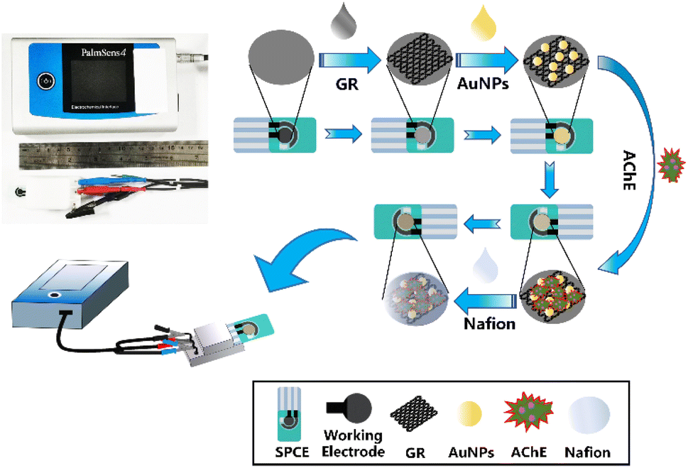
10 μL of 0.05–0.35 mg mL−1 GR dispersion was applied on the surface of the pretreated SPCE working electrode. After drying at room temperature, 10 μL of 50–200 μg mL−1 AuNPs dispersion was applied, dried at room temperature, and then applied by dropwise application. 7.5 μL (0.2–1.4 U) of AChE buffer, dry in a 4 °C freezer. Finally, 5 μL of 1% Nafion solution was used to encapsulate the electrode surface and then placed in a 4 °C refrigerator to dry before use. The preparation process of the sensor was shown in Fig. 1. For comparison, SPCE/AChE/Nafion and SPCE/GR/AChE/Nafion electrodes were also prepared.
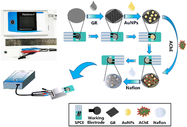 |
| | Fig. 1 Preparation process of SPCE/GR/AuNPs/AChE/Nafion. | |
2.5 Electrochemical measurement
Cyclic voltammetry (CV), alternating impedance spectroscopy (EIS) and differential pulse voltammetry (DPV) were performed on the prepared sensor. The test solution for cyclic voltammetry (CV) was a mixed solution of 0.1 M KCl and 5 mM K3[Fe(CN)6]/K4[Fe(CN)6] (1![[thin space (1/6-em)]](https://www.rsc.org/images/entities/char_2009.gif) :1), and the scanning speed was set to 100 mV s−1, the voltage range is −0.6 to 0.8 V.
:1), and the scanning speed was set to 100 mV s−1, the voltage range is −0.6 to 0.8 V.
The EIS test solution was the same as the CV, and the detection was performed in the frequency range of 0.01–100 kHz with an open circuit potential of 0.125 V and a step potential of 10 mV. These two measurements were used to characterize the effect of electrode surface modification by incorporation of nanomaterials. DPV tests were performed in PBS solution (pH = 7.5) containing 1 mM ATCl. The test potentials ranged from 0.3 to 1.1 V, with a pulse width of 0.05 s, a pulse period of 0.02 s, a modulation amplitude of 0.05 V, and a resting time of 2 s. The peak current of the DPV test is used to optimize the test conditions of the sensor. In addition, the calculation of the inhibition rate is obtained as follows:
| Inhibition (%) = (I0 − I1)/I1 × 100 |
where
I0 is the initial peak current of the sensor in the test solution and
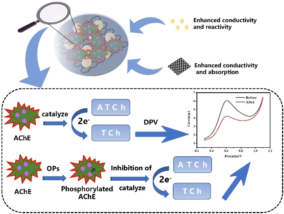
I1 is the peak current of the sensor in the test solution after it has been inhibited by a certain concentration of ICP. Finally, the calibration curve of the relationship between inhibition rate and different concentrations of ICP was obtained, and the principle of inhibition was shown in
Fig. 2.
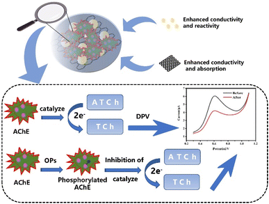 |
| | Fig. 2 Schematic diagram of SPCE/GR/AuNPs/AChE/Nafion sensor for OPs detection. | |
2.6 The detection of the real samples
The cucumbers used as real samples in the study were purchased from a local vegetable market (Changsha, China). 5 g of cucumber peels were placed in a solution containing 20 mL of ultrapure water and 20 mL of acetone for 10 min, sonicated for 30 min, and then filtered. The filtrate was concentrated by rotary evaporation at 70 °C and then filtered through a 0.22 μm filter membrane to obtain the supernatant. Different known concentrations of ICP standards were added to it to make spiked samples. Three measurements were made using different sensors and the corresponding concentration values were obtained from the standard curve. It was divided by the actual spiked concentration to calculate the recovery of the sample. Alternatively, ICP standards were added directly to the tap water samples to make spiked samples, and the testing procedure was the same as above.
3 Results and discussion
3.1 Characterization of SPCE/GR/AuNPs/AChE/Nafion electrodes
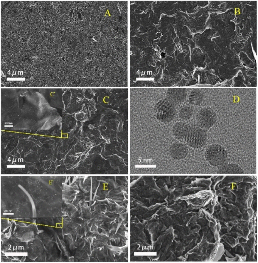
The morphology of the materials and the changes of surface morphology during the assembly of SPCE/GR/AuNPs/AChE/Nafion electrodes were investigated by TEM and SEM methods, as shown in Fig. 3. Fig. 3(A) showed the SEM image of the pristine SPCE, whose surface was not smooth, with numerous pores and small cavities. Fig. 3(B) showed the morphology of SPCE/GR, and a typical wrinkled structure of graphene was observed. The graphene sheets with small thickness uniformly laid flat on the surface of SPCE will facilitate the electron transfer and the material loading. In Fig. 3(C) and (C′), gold particles were uniformly dispersed on the wrinkled graphene lamellae. The TEM image in Fig. 3(D) showed that the gold particles had a complete spherical morphology with a diameter of about 3–5 nm. In Fig. 3(E), ice-pick-like structures were shown embedded or laid flat on the graphene surface, which may be the crystallization of AChE in Tris–HCl buffer. Finally, a layer of Nafion film was observed wrapping the SPCE surface in Fig. 3(F), providing a more stable environment for the composite. Therefore, the above results indicated that the composite material was successfully immobilized on the electrode surface as expected.
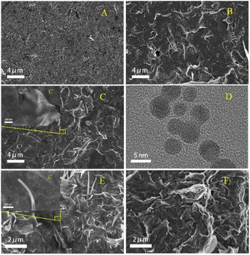 |
| | Fig. 3 SEM image of (A) bare SPCE, (B) SPCE/GR, (C, C′) SPCE/GR/AuNPs, (E, E′) SPCE/GR/AuNPs/AChE, and (F) SPCE/GR/AuNPs/AChE/Nafion; (D) TEM image of AuNPs. | |
3.2 Electrochemical properties during electrode assembly process
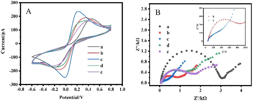
The electrochemical behavior during the assembly of SPCE/GR/AuNPs/AChE/Nafion electrodes was studied by CV and EIS, as shown in Fig. 4. Curve a in Fig. 4(A) is the CV curve of unmodified bare SPCE, and a pair of distinct redox peaks can be observed. When the electrode was modified by GR (curve b), it showed a larger current response due to the good electrical conductivity of GR. The reduction of the potential difference between the oxidation peak and the reduction peak indicated that the reaction rate on the electrode surface was accelerated. After loading AuNPs on the GR surface (curve c), it formed a synergistic effect with GR, which led to a further acceleration of the reaction rate on the electrode surface and a significant enhancement of the redox peak current. When AChE was modified to the electrode surface, the redox peak current decreased significantly (curve d). This is because enzymes are macromolecular proteins with poor conductivity, which hinder the progress of the reaction on the electrode surface. Finally, since the conductivity of the Nafion film is also not superior, it is also a hindrance to the reaction on the electrode surface as an encapsulation layer (curve e).
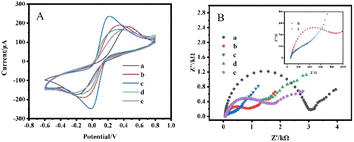 |
| | Fig. 4 CV curves (A) and Nyquist diagrams (B) of SPCE/GR/AuNPs/AChE/Nafion electrode assembly process in 5 mM Fe(CN)63−/4− (1:1) test solution containing 0.1 M KCl: (a) bare SPCE, (b) SPCE/GR, (c) SPCE/GR/AuNPs, (d) SPCE/GR/AuNPs/AChE, (e) SPCE/GR/AuNPs/AChE/Nafion. | |
EIS is a powerful electrochemical test method for probing the interfacial properties of electrodes during different modifications. A typical Nyquist diagram consists of a high-frequency semicircular region associated with an electron transfer-limited process and a low-frequency linear part associated with a diffusion-limited process. The diameter of the semicircle is usually used to estimate the electron transfer resistance (Rct). In Fig. 4(B), curve a depicted a bare SPCE with an Rct of about 3000 Ω. The modification of GR facilitated the electron transfer at the electrode interface, and the Rct was reduced to 850 Ω (curve b). After the modification of the electrode by AuNPs, the Rct was significantly reduced and the semicircular curve was almost converted to linear (curve c). This indicated a good synergy between GR and AuNPs in improving electron transfer at the electrode interface. The loading of the AChE led to a significant increase in Rct to 1400 Ω (curve d). Finally, the encapsulation of the Nafion film increases the Rct to 1850 Ω. The conclusion of the EIS test was consistent with the CV study, and the above results showed that the composite material was successfully loaded on the electrode.
3.3 Optimization parameters of the biosensor performance
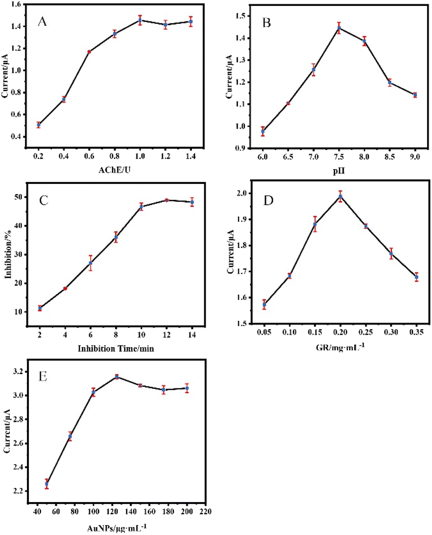
The key factors which can significantly affect the performance of the AChE biosensor, including AChE loading concentration, pH of the detection solution, and inhibition time, amount of GR modification, and amount of AuNPs modification were optimized. The result of optimization of AChE loading was shown in Fig. 5(A), the maximum current response was obtained with a loading of 1.0 U. The sensor with a small amount of AChE has a small current response due to its insufficient ability to catalyze the ATCl hydrolysis reaction, but too much loading does not allow more effective catalysis, because the active center of AChE is deep in its structure, and even may lead to poor conductivity of the electrode. The pH value has a large effect on AChE activity, with the current response reaching a maximum at pH = 7.5(Fig. 5(B)). Fig. 5(C) showed the ICP incubation process of the SPCE/AChE/Nafion sensor by a certain concentration of ICP. The inhibition rate of the current response in the range of 2–9 min increases significantly with the increase of the response time. When the incubation time exceeded 10 min, the inhibition rate increased insignificantly, indicating that the phosphorylation process of AChE was largely completed around 10 min. Fig. 5(D) showed that the current response increases and then decreases with the addition of GR, which may be related to the degree of GR covering the electrode. A moderate amount of GR covering the electrode surface can significantly improve the conductivity, but too thick surface accumulation is not conducive to the transfer of electrons. Fig. 5(E) showed that the modification amount of AuNPs can reach saturation at about 125 μg mL−1, and the current response cannot be further improved by increasing the amount. Combined with the above results, subsequent experiments were carried out under the above optimal conditions.
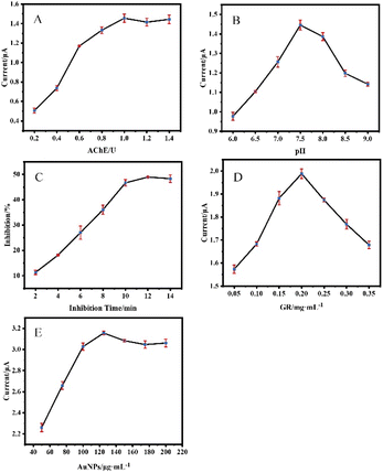 |
| | Fig. 5 Effects of (A) AChE loading, (B) effect of pH value of PBS solution, (D) GR addition, and (E) AuNPs addition on sensor response current; (C) effect of ICP incubation time on sensor inhibition rate. | |
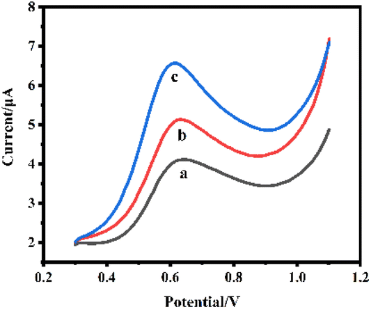
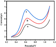
After optimization of the conditions, we compared the DPV responses of three sensors of (a) SPCE/AChE/Nafion, (b) SPCE/GR/AChE/Nafion, and (c) SPCE/GR/AuNPs/AChE/Nafion in PBS buffer (pH = 7.5) containing 1 mM substrate ATCl as shown in Fig. 6.
 |
| | Fig. 6 DPV curves of different prepared sensors in PBS solution (pH = 7.5) containing 1 mM ATCl: (a) SPCE/AChE/Nafion, (b) SPCE/GR/AChE/Nafion, (c) SPCE/GR/AuNPs/AChE/Nafion. | |
They all showed a clear peak around 0.6 V. The peak was derived from the oxidation peak of thiocholine, a product of the AChE-catalyzed hydrolysis of the immobilized substrate ATCl. It can be found that the enzyme sensor constructed with bare SPCE produced the smallest oxidation peak current (curve a), and the oxidation current of the sensor increased significantly after the GR modification (curve b). The addition of AuNPs led to a further increase in the oxidation peak current (curve c). The above experimental results fully demonstrated that the GR and AuNPs composites can effectively increase the electron transfer rate and better maintain the activity of AChE, which enhanced the current response and helps to improve the performance of the sensor.
3.4 Determination of ICP
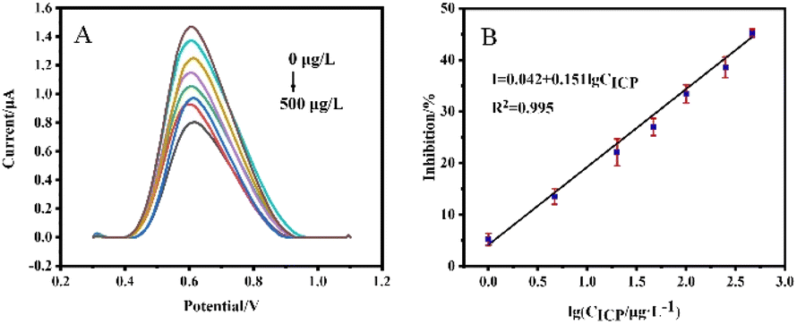
Under the optimal experimental conditions (AChE loading of 1.0 U, pH = 7.5 of the detection solution, and ICP incubation time of 10 min), we first investigated the DPV response changes of the SPCE/AChE/Nafion sensor after incubation with different concentrations of ICP, as shown in Fig. 7(A). An obvious peak appeared at about 0.6 V, which was derived from the oxidation peak of thiocholine, the product of the hydrolysis of the immobilized AChE-catalyzed substrate ATCl. As the ICP concentration gradually increased, the DPV response gradually decreased. The calibration curve between the inhibition rate and the logarithmic value of ICP concentration was shown in Fig. 7(B). The linear equation was I = 0.042 + 0.151 × lgCICP (R2 = 0.995) with a detection limit of 0.77 μg L−1 (S/N = 3).
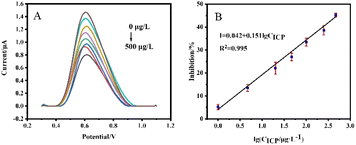 |
| | Fig. 7 (A) DPV curves of SPCE/AChE/Nafion sensors in PBS solution (pH = 7.5) containing 1 mM ATCl after being inhibition by different concentrations of ICP for 10 min. ICP concentrations: 0, 1, 5, 20, 50, 100, 250, 500 μg L−1; (B) calibration curve of the inhibition rate of DPV peak current of SPCE/AChE/Nafion sensor versus the logarithmic value of ICP concentration. | |
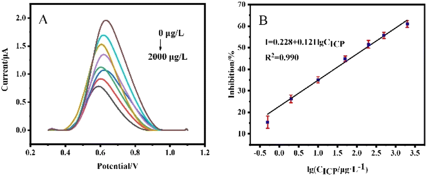
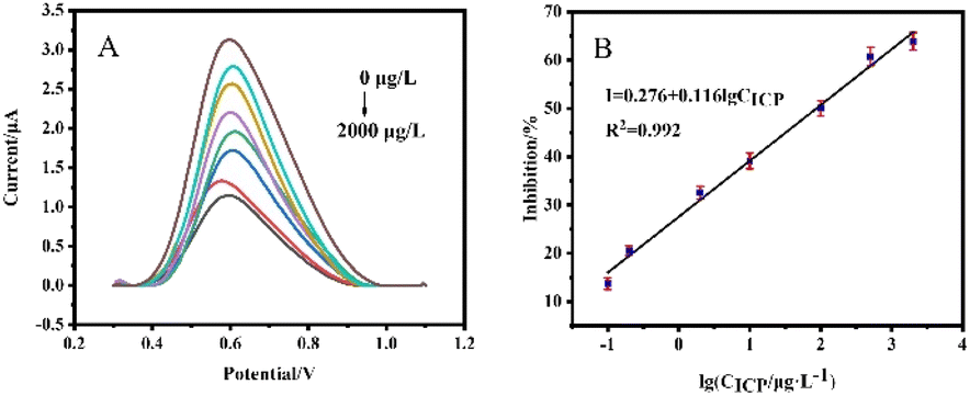
For the comparison of sensor performance before and after modification, the DPV responses of the SPCE/GR/AChE/Nafion sensor and SPCE/GR/AuNPs/AChE/Nafion sensor after incubation with different concentrations of ICP were investigated, as shown in Fig. 8 and 9. The linear equation of the calibration curve of SPCE/GR/AChE/Nafion sensor was I = 0.228 + 0.121 × lgCICP (R2 = 0.990), and the detection limit is 0.041 μg L−1 (S/N = 3). The linear equation of the calibration curve of SPCE/GR/AuNPs/AChE/Nafion sensor was I = 0.276 + 0.116 × lgCICP (R2 = 0.992), and the detection limit is 0.012 μg L−1 (S/N = 3). The results showed that the detection performance of the sensor constructed by SPCE after the co-modification of GR and AuNPs was significantly improved, and the response to ICP suppression was more obvious, with a wider linear range and lower detection limits.
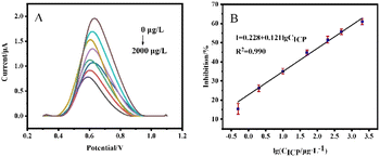 |
| | Fig. 8 (A) DPV curves of SPCE/GR/AChE/Nafion sensors in PBS solution (pH = 7.5) containing 1 mM ATCl after being inhibition by different concentrations of ICP for 10 min. ICP concentrations: 0, 0.5, 2, 10, 50, 100, 500, 2000 μg L−1; (B) calibration curve of the inhibition rate of DPV peak current of SPCE/GR/AChE/Nafion sensor versus the logarithmic value of ICP concentration. | |
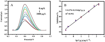 |
| | Fig. 9 (A) DPV curves of SPCE/GR/AChE/Nafion sensors in PBS solution (pH = 7.5) containing 1 mM ATCl after being inhibition by different concentrations of ICP for 10 min. ICP concentrations: 0, 0.1, 0.2, 2, 10, 100, 500, 2000 μg L−1; (B) calibration curve of the inhibition rate of DPV peak current of SPCE/GR/AChE/Nafion sensor versus the logarithmic value of ICP concentration. | |
As far as we know, an AChE sensor using the DPV method for ICP detection has never been reported before. Therefore, it was compared with the performance of a fraction of AChE sensors reported in recent years for the determination of other OPs. As shown in Table 1, the sensor proposed in this work have comparable or even wider linear ranges and lower detection limits. In addition, the linear range includes the Chinese national limited standard value of organophosphorus pesticide residue detection in agricultural products (0.2 mg kg−1). Considering the simplicity and portability, this work will have more practical application value.
Table 1 Performance comparison of AChE sensors for OPs detection by DPV method
| Method |
Target |
Linear range (μg L−1) |
Detection limit (μg L−1) |
Ref. |
| Au/MWCNTs-SnO2-CHIT/AChE/Nafion |
Chlorpyrifos |
0.05–1 × 10⁵ |
0.05 |
40 |
| Au/Chit-PB-MWNTs-HGNs/AChE/Nafion |
Malathion |
0.017–25 |
0.017 |
41 |
| GCE/AChE/IL1-MWCNTs |
Monocrotophos |
0.022–112 |
0.0074 |
42 |
| GCE/CNT-NH2/AChE |
Paraoxon |
0.055–0.275, 0.275–8.25 |
0.022 |
43 |
| GCE/RGO-PDA-AuNPs-AgNPs-AChE-CS |
Methylparathion |
0.019–800 |
0.0024 |
44 |
| GCE/‘AuNRs@MS’@TiO2-CS/CS/AChE |
Fenthion |
5–3780 |
0.36 |
45 |
| GCE/CS&rGO/AuNPs/TiO2-NRs/AChE |
Dichlorvos |
0.5–125 |
0.49 |
46 |
| GCE/GR/Ti3C2Tx-CS/AChE |
Dichlorvos |
4–2500 |
3.19 |
47 |
| SPCE/DCHP/MWCNTs/AChE |
Chlorpyrifos |
0.05–1.0 × 10⁵ |
0.05 |
48 |
| SPCE/ATO-CS/OMC-CS/AChE |
Chlorpyrifos |
0.01–105 |
0.01 |
49 |
| SPCE/Fe3O4-CS/OMC-CS/AChE |
Methamidophos |
1–600 |
1 |
50 |
| SPCE/CeO2-CS/OMC-CS/AChE |
Methamidophos |
1–600 |
1 |
51 |
| SPCE/GR/AuNPs/AChE/Nafion |
Isocarbophos |
0.1–2000 |
0.012 |
This work |
3.5 Repeatability, stability and anti-interference studies
Five SPCE/GR/AuNPs/AChE/Nafion sensors were prepared using the same method. ICP at 10 μg L−1 was selected for assessing the repeatability of this biosensor, and the results (Fig. S1†) showed that the relative standard deviation of the assay was 4.2%, thus, the sensor had good repeatability.
The prepared sensor was stored in a refrigerator at 4 °C. As shown in Fig. S2,† after a storage period of 15 days, the sensor maintained 96% of the initial current response, and after a storage period of 30 days, the response of the sensor changed to 82% of the initial current response, revealing desirable stability.
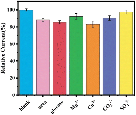
Some potential interfering substances in the actual environmental detection were selected for the anti-interference study of the sensor, such as glucose contained in fruits, urea often used in fertilizers, Mg2+, SO42−, CO32−, which are more abundant in natural water bodies, and the influence of metal ions such as Cu2+, and their concentration was set to be 5 times of the ATCl concentration, as shown in Fig. 10. The results showed that 5 times of ATCl concentration of glucose, urea and Cu2+ slightly decreased the sensor current, and there was no significant decrease in the current response of the sensor in the presence of other interferents. Therefore, the sensor has a good immunity to interference.
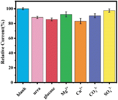 |
| | Fig. 10 Current response of SPCE/GR/AuNPs/AChE/Nafion sensors in the presence of different interferents. | |
3.6 Real sample analysis
Finally, cucumber and tap water were selected as the actual sample test objects, and ICP with known concentration was added to conduct the average recovery test to evaluate the practical application ability of SPCE/GR/AuNPs/AChE/Nafion biosensors. The results showed that the recoveries ranged from 92.51% to 110.41% (Table 2). Therefore, the assembled biosensor exhibits good accuracy in detecting OPs in real samples and has great potential for practical applications.
Table 2 ICP recovery study of SPCE/GR/AuNPs/AChE/Nafion sensors in cucumber and tap water samples
| Sample |
Added (μg L−1) |
Recovery (%) |
RSD (%) |
| Cucumber peel |
2 |
101.74 |
1.71 |
| Cucumber peel |
10 |
94.57 |
4.00 |
| Tap water |
2 |
90.57 |
2.72 |
| Tap water |
10 |
108.90 |
3.60 |
4 Conclusions
From the perspective of miniaturization and portability of organophosphorus detection, an new AChE electrochemical sensor was constructed by layer-by-layer drop coating method based on SPCE and small electrochemical workstation, and nanomaterials GR and AuNPs were introduced to enhance electron transfer capability and increase reactivity, thus amplifying signal and improving sensing performance, and Nafion with low impedance, good film formation and biocompatibility was used for encapsulation to reduce the loss of modifiers. The sensor is capable of detecting ICP over a wide linear range from 0.1 μg L−1 to 2000 μg L−1, with the limit of detection as low as 0.012 μg L−1. It has good repeatability, interference resistance and storage stability. Satisfactory results were also obtained in the recovery studies of cucumber rind and tap water samples. The strategy has the advantages of simple fabrication, low cost and portability, and is expected to be extended to the field detection of other organophosphorus in the environment, which is an important step for rapid detection of nerve agents in the field.
Conflicts of interest
The authors declare that they have no known competing financial interests or personal relationships that could have appeared to influence the work reported in this paper.
Acknowledgements
We thank for the funding of Independent Scientific Research Project of National University of Defense Technology (ZZKY-YX-09-04).
References
- M. Kloske and Z. Witkiewicz, Chemosphere, 2019, 221, 672–682 CrossRef CAS PubMed.
- H. Sanderson, War and Environmental Health: Chemical Warfare Agents, Reference Module in Earth Systems and Environmental Sciences, 2018 Search PubMed.
- S. R. Emmett and P. G. Blain, Medicine, 2020, 48, 182–184 CrossRef.
- S. Sezigen, K. Ivelik, M. Ortatatli, M. Almacioglu, M. Demirkasimoglu, R. Eyison, Z. Kunak and L. Kenar, Toxicol. Lett., 2019, 303, 9–15 CrossRef CAS PubMed.
- R. Pita, A. Anadón, A. Romero and K. Kuca, in Handbook of toxicology of chemical warfare agents, Elsevier, 2020, pp. 79–94 Search PubMed.
- M. Fitzpatrick, Survival, 2013, 55, 107–114 CrossRef.
- V. Aroniadou-Anderjaska, J. P. Apland, T. H. Figueiredo, M. D. A. Furtado and M. F. Braga, Neuropharmacology, 2020, 181, 108298 CrossRef CAS PubMed.
- E. J. Hulse, J. D. Haslam, S. R. Emmett and T. Woolley, Br. J. Anaesth., 2019, 123, 457–463 CrossRef CAS PubMed.
- S. Vucinic, B. Antonijevic, A. M. Tsatsakis, L. Vassilopoulou, A. O. Docea, A. E. Nosyrev, B. N. Izotov, H. Thiermann, N. Drakoulis and D. Brkic, Environmental Toxicology and Pharmacology, 2017, 56, 163–171 CrossRef CAS PubMed.
- H. John and H. Thiermann, J. Mass Spectrom. Adv. Clin. Lab, 2021, 19, 20–31 CrossRef CAS PubMed.
- A. Vale, T. C. Marrs and P. Rice, Medicine, 2016, 44, 106–108 CrossRef.
- H. Thiermann, L. Szinicz, P. Eyer, N. Felgenhauer, T. Zilker and F. Worek, Toxicology, 2007, 233, 145–154 CrossRef CAS PubMed.
- T. O. Ajiboye, P. O. Oladoye, C. A. Olanrewaju and G. O. Akinsola, Environ. Nanotechnol. Monit. Manag., 2022, 100655 CAS.
- H. Fu, P. Tan, R. Wang, S. Li, H. Liu, Y. Yang and Z. Wu, J. Hazard. Mater., 2022, 424, 127494 CrossRef CAS PubMed.
- A. Derbalah, R. Chidya, W. Jadoon and H. Sakugawa, J. Environ. Sci., 2019, 79, 135–152 CrossRef CAS PubMed.
- I. Mangas, E. Vilanova, J. Estévez and T. C. França, J. Braz. Chem. Soc., 2016, 27, 809–825 CAS.
- Z. Li, J. Sun and L. Zhu, Sci. Total Environ., 2021, 765, 142757 CrossRef CAS PubMed.
- U. Jain, K. Saxena, V. Hooda, S. Balayan, A. P. Singh, M. Tikadar and N. Chauhan, Food Chem., 2022, 371, 131126 CrossRef CAS PubMed.
- J. I. Cacho, N. Campillo, P. Viñas and M. Hernández-Córdoba, J. Chromatogr., A, 2018, 1559, 95–101 CrossRef CAS PubMed.
- R. Su, X. Xu, X. Wang, D. Li, X. Li, H. Zhang and A. Yu, J. Chromatogr. B, 2011, 879, 3423–3428 CrossRef CAS PubMed.
- P. G. Arias, H. Martínez-Pérez-Cejuela, A. Combès, V. Pichon, E. Pereira, J. M. Herrero-Martínez and M. Bravo, J. Chromatogr., A, 2020, 1626, 461346 CrossRef CAS PubMed.
- D. Harshit, K. Charmy and P. Nrupesh, Food Chem., 2017, 230, 448–453 CrossRef CAS PubMed.
- C. García-Ruiz, G. Alvarez-Llamas, Á. Puerta, E. Blanco, A. Sanz-Medel and M. L. Marina, Anal. Chim. Acta, 2005, 543, 77–83 CrossRef.
- M. Tefera, M. Tessema, S. Admassie, M. Ward, L. Phelane, E. I. Iwuoha and P. G. Baker, Anal. Chim. Acta, 2021, 9, 100077 CrossRef CAS PubMed.
- G. Xu, J. Hou, Y. Zhao, J. Bao, M. Yang, H. Fa, Y. Yang, L. Li, D. Huo and C. Hou, Sensor. Actuator. B Chem., 2019, 287, 428–436 CrossRef CAS.
- A. Talan, A. Mishra, S. A. Eremin, J. Narang, A. Kumar and S. Gandhi, Biosens. Bioelectron., 2018, 105, 14–21 CrossRef CAS PubMed.
- T. V. Kumar and A. K. Sundramoorthy, Anal. Chim. Acta, 2019, 1074, 131–141 CrossRef CAS PubMed.
- X. Tan, J. Wu, Q. Hu, X. Li, P. Li, H. Yu, X. Li and F. Lei, Anal. Methods, 2015, 7, 4786–4792 RSC.
- J. B. Thakkar, S. Gupta and C. R. Prabha, Int. J. Biol. Macromol., 2019, 137, 895–903 CrossRef CAS PubMed.
- G. Xu, D. Huo, C. Hou, Y. Zhao, J. Bao, M. Yang and H. Fa, Talanta, 2018, 178, 1046–1052 CrossRef CAS PubMed.
- J. Bao, T. Huang, Z. Wang, H. Yang, X. Geng, G. Xu, M. Samalo, M. Sakinati, D. Huo and C. Hou, Sensor. Actuator. B Chem., 2019, 279, 95–101 CrossRef CAS.
- X. Lu, L. Tao, Y. Li, H. Huang and F. Gao, Sensor. Actuator. B Chem., 2019, 284, 103–109 CrossRef CAS.
- L. Ma, L. Zhou, Y. He, L. Wang, Z. Huang, Y. Jiang and J. Gao, Electroanalysis, 2018, 30, 1801–1810 CrossRef.
- Y. Jiang, X. Zhang, L. Pei, S. Yue, L. Ma, L. Zhou, Z. Huang, Y. He and J. Gao, Chem. Eng. J., 2018, 339, 547–556 CrossRef CAS.
- S. Cinti, D. Neagu, M. Carbone, I. Cacciotti, D. Moscone and F. Arduini, Electrochim. Acta, 2016, 188, 574–581 CrossRef CAS.
- P. Qi, J. Wang, X. Wang, X. Wang, Z. Wang, H. Xu, S. Di, Q. Wang and X. Wang, Electrochim. Acta, 2018, 292, 667–675 CrossRef CAS.
- E. A. Songa and J. O. Okonkwo, Talanta, 2016, 155, 289–304 CrossRef CAS PubMed.
- A. G.-M. Ferrari, S. J. Rowley-Neale and C. E. Banks, Talanta, 2021, 3, 100032 CrossRef.
- N. Wang, Z. Liu, L. Wen, B. Zhang, C.-a. Tao and J. Wang, Talanta, 2022, 236, 122822 CrossRef CAS PubMed.
- D. Chen, X. Sun, Y. Guo, L. Qiao and X. Wang, Bioprocess Biosyst. Eng., 2015, 38, 315–321 CrossRef CAS PubMed.
- C. Zhai, X. Sun, W. Zhao, Z. Gong and X. Wang, Biosens. Bioelectron., 2013, 42, 124–130 CrossRef CAS PubMed.
- Z. Bin, C. Yanhong, X. Jiaojiao and Y. Jing, Anal. Biochem., 2018, 560, 12–18 CrossRef CAS PubMed.
- G. Yu, W. Wu, Q. Zhao, X. Wei and Q. Lu, Biosens. Bioelectron., 2015, 68, 288–294 CrossRef CAS PubMed.
- X. Chen, J. Wang, Z. Liu, Y. Li, J. Huang and C.-A. Tao, Mater. Res. Express, 2019, 6, 105093 CrossRef CAS.
- H.-F. Cui, T.-T. Zhang, Q.-Y. Lv, X. Song, X.-J. Zhai and G.-G. Wang, Biosens. Bioelectron., 2019, 141, 111452 CrossRef CAS PubMed.
- J. Zhang, H. Hu and L. Yang, Microchem. J., 2021, 168, 106435 CrossRef CAS.
- B. Wang, Y. Li, H. Hu, W. Shu, L. Yang and J. Zhang, PLoS One, 2020, 15, 231981 Search PubMed.
- D. Chen, Z. Liu, J. Fu, Y. Guo, X. Sun, Q. Yang and X. Wang, J. Electroanal. Chem., 2017, 801, 185–191 CrossRef CAS.
- W. Hou, Q. Zhang, H. Dong, F. Li, Y. Zhang, Y. Guo and X. Sun, New J. Chem., 2019, 43, 946–952 RSC.
- Q. Zhang, Q. Xu, Y. Guo, X. Sun and X. Wang, RSC Adv., 2016, 6, 24698–24703 RSC.
- J. Fu, Int. J. Electrochem. Sci., 2018, 9231–9241, DOI:10.20964/2018.09.146.
|
| This journal is © The Royal Society of Chemistry 2023 |
Click here to see how this site uses Cookies. View our privacy policy here. 
 Open Access Article
 This Open Access Article is licensed under a Creative Commons Attribution-Non Commercial 3.0 Unported Licence
 *,
Zhuoliang Liu,
Cheng-an Tao
*,
Zhuoliang Liu,
Cheng-an Tao