DOI:
10.1039/D2NA00896C
(Paper)
Nanoscale Adv., 2023,
5, 1936-1942
A hydrangea-like nitrogen-doped ZnO/BiOI nanocomposite for photocatalytic degradation of tetracycline hydrochloride†
Received
7th December 2022
, Accepted 14th February 2023
First published on 15th February 2023
Abstract
The effectiveness of photocatalysts can be impacted by the high compounding efficiency of photogenerated carriers, which depends on the morphology of the photocatalyst. Here, a hydrangea-like N–ZnO/BiOI composite has been prepared for achieving efficient photocatalytic degradation of tetracycline hydrochloride (TCH) under visible light. The N–ZnO/BiOI exhibits a high photocatalytic performance, degrading nearly 90% of TCH within 160 min. After 3 cycling runs, the photodegradation efficiency remained above 80%, demonstrating its good recyclability and stability. The major active species at work are superoxide radicals (·O2−) and photo-induced holes (h+) in the photocatalytic degradation of TCH. This work provides not only a new idea for the design of photodegradable materials but also a new method for the effective degradation of organic pollutants.
1 Introduction
Tetracycline hydrochloride (TCH) is a common pharmaceutical and personal care product (PPCP), which is widely used around the world due to its high quality and low cost. Unfortunately, TCH is not easily degraded with high resistance due to the complex molecular structure and hepatotoxicity,1,2 even worse, its residues can remain in the water and soil for a long time, resulting in the appearance of the drug resistance genes and endangering human and environmental health.3,4 Conventional treatment technologies of TCH in the water system include chemical precipitation, biodegradation, ozonation, physical adsorption, and photocatalytic degradation.5–7 Among these technologies, photocatalysis, one of the advanced oxidation processes (AOPs), has been attracting considerable attention due to its pollution-free, eco-friendly, and efficiency.8–11 However, most conventional photocatalysis can only use ultraviolet light, which accounts for only 5% of the sunlight,12 such as TiO2. To improve the utilization of light, there is an increasing emphasis on photodegradable materials that can be used to operate under visible light.
BiOX (X = I, Br, CI), as a ternary semiconductor, contains two halogen atoms and [Bi2O2]2+ plate interconnection,13,14 which provides excellent photocatalytic activity in the removal of pollutants due to the layered tetragonal crystal structure for BiOX.15 In detail, the layered structure of BiOX allows the related atoms and orbitals to be polarized, which induces dipole efficiently separating electron–hole pairs.16 Amongst them, BiOI may be the most viable alternative for eliminating TCH effluent due to the smallest band gap of about 1.77–1.92 eV, which has a strong visible light response.17,18 In contrast to the layered nanosheet form, the intended 3D hierarchical structure of BiOI is more favorable to the separation for photogenerated carriers19,20 and also facilitates the recovery.21 Nevertheless, the activity of BiOI is greatly inhibited by a high recombination rate of photo-generated charge carriers.22,23 Numerous strategies have been used to address this issue, including surface modification,24 defect effect,25 and heterojunction construction.26
Recently, zinc oxide (ZnO) has gradually become one of the most extensively researched photocatalysts due to its eco-friendly nature, low cost, and effective electron–hole separation ability in the photocatalytic process.27,28 Nevertheless, ZnO, as a wide bandgap semiconductor (∼3.20 eV), has a narrow photoresponse range and responds mainly to UV light, which limits its application.29–31 To overcome this limitation, some researchers found that carbon materials could promote photoelectronic transformation because their excellent electron conductivity can facilitate the efficient utilization of spatial charge carriers.21,32,33 Meanwhile, metal–organic frameworks (MOFs), a porous substance created by the self-assembly of metal ions or clusters and organic linkers, have attracted a lot of interest in a number of domains, including photocatalysis.34–36 MOFs could be an effective scaffold for catalysis due to their structured porosity structure, coordination-unsaturated metal sites, and changeable organic linkers which could facilitate the generation and separation of charge carriers.37 Among them, zeolitic imidazolate frameworks (ZIFs) as a basic member of MOFs receive a lot of attention owing to their structural diversity and superb chemical and thermal stability.38 Recently, metal oxides formed by low temperature-carbonization MOFs have been chosen for application in photocatalysis owing to combining the structure advantages of MOF and carbon materials, including high porosity, uniform heteroatom doping, and functionalization.39,40 Hence, ZnO was obtained by low-temperature carbonization of ZIF-L, which not only preserves the benefits of the metal–organic framework but also successfully addresses the problems of rapid compounding of ZnO photogenerated carriers.41 Additionally, it is reported that nitrogen atoms can substitute for oxygen atoms in ZnO to create an intermediate energy level (referred to as the N 2p defect state), which is placed above the O 2p energy level in N-doped ZnO and narrows the band gap.42
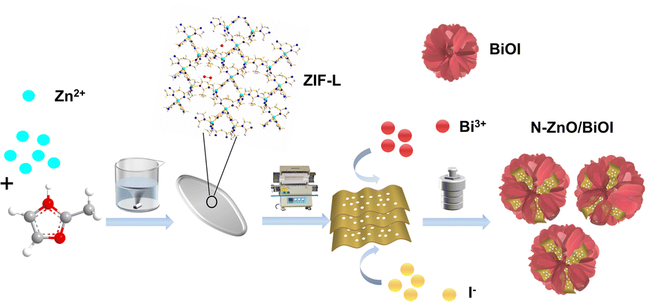
Therefore, the N–ZnO synthesized by low-temperature carbonization of ZIF-L was combined with BiOI to generate the N–ZnO/BiOI with the intended 3D hierarchical structure, which strategy can prepare a photocatalytic degradation material with more excellent performance, as shown in Scheme 1. In detail, ZIF-L was used as a sacrificial agent to prepare porous carriers of ZnO, and subsequently BiOI nanosheets grew in situ on the inner surface of porous ZnO nanoparticles by a solvothermal method to prepare a stable “hydrangea-like” N–ZnO/BiOI composite. Next, the THC was used to assess the photocatalytic activity of the N–ZnO/BiOI nanocomposite. Under visible light, the photocatalytic activity of the N–ZnO/BiOI for TCH was significantly improved compared to pristine BiOI and N–ZnO, demonstrating excellent potential for practical applications.
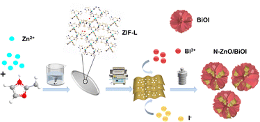 |
| | Scheme 1 Schematic illustration of the preparation procedure of the N–ZnO/BiOI compounds. | |
2 Experiments
2.1 Materials and regents
During the experimental procedures, all regents were of analytical grade and were used without further purification. 2-Methylimidazole (MIM) and zinc nitrate hexahydrate (Zn(NO3)2·6H2O) were purchased from Zhan Yun Ltd, Shanghai, China and Da Mao Ltd, Tianjin China respectively. Ethylene glycol (EG) was purchased from Lian Long Ltd, Tianjin China. Bismuth nitrate pentahydrate (Bi(NO3)3·5H2O) and potassium iodide (KI) were purchased from Aladdin Reagent Co., Ltd, Shanghai China. Ultra-pure water was used throughout the study.
2.2 Characterization
X-ray powder diffraction (XRD, Bruker D8 Advance diffractometer, λ = 1.5418 Å) with Cu Kα radiation was used to examine the crystal structure of the as-synthesized samples. X-ray photoelectron spectroscopy with Al Kα (XPS, Kratos Analytical Ltd) was employed to detect surface electronic states. Scanning electron microscopy (SEM, Carl Zeiss-Ultra Plus, Germany) and energy dispersive X-ray spectroscopy (EDS) were used to characterize the micromorphology of the products at an accelerating voltage of 5.0 kV. The structure of the samples was characterized by transmission electron microscopy (TEM, FEI Tecnai G2 F20, USA) with an accelerating voltage of 200 kV. UV-visible diffuse reflectance spectra (UV-vis DRS) and the photoluminescence spectrum (PL) were obtained on an ultraviolet-visible spectrometer (Lambda 950+Refle) and FLS920 spectrophotometer, respectively. Raman spectra were recorded on an in via Raman spectrometer (Rainie Salt Public Co. Ltd, Britain). Electrochemical impedance spectroscopy (EIS) was conducted on an electrochemical workstation (CHI-710E, Shanghai Chenhua, China).
2.3 Synthesis of N–ZnO and N–ZnO/BiOI
First, the 1.313 g 2-methylimidazole (MIM) and 0.595 g zinc nitrate hexahydrate (Zn(NO3)2·6H2O) were dispersed in 40 mL deionized water, respectively. The mixture was blended quickly and stirred slowly for 4 h; the white sediment known as ZIF-L was produced. The products were then repeatedly centrifuged with ultra-pure water and dried at 60 °C overnight.43 Finally, in order to obtain N–ZnO nanosheets, the synthesized ZIF-L was calcined at 400 °C for 2 h with a heating rate of 2 °C min in an air-filled tubular furnace.41
The N–ZnO/BiOI composites were prepared by a solvothermal reaction. Typically, 0.485 g bismuth nitrate pentahydrate (Bi(NO3)3·5H2O) was dispersed in 10 mL ethylene glycol, then various amounts of N–ZnO were added to the Bi(NO3)3·5H2O solution for sonicating 30 min to obtain solution A. 0.166 g KI was added to 10 mL of ethylene glycol and sonicated for 30 min to get solution B. Following that, as-prepared solution B was gradually added to solution A and the mixture was stirred for 1 h. After mixing, it was transferred to a 100 mL Teflon-lined stainless-steel autoclave and kept at 160 °C for 24 h.44 The resulting product was washed with deionized water and anhydrous ethanol in sequence before being dried at 70 °C overnight. During this time, we separately added 0, 25, 50, and 100 mg N–ZnO to solution A, and labeled them as BiOI, N–ZnO/BiOI-1, N–ZnO/BiOI-2 and N–ZnO/BiOI-3, respectively.
2.4 Photocatalytic degradation of TCH
Regarding the capacity of TCH for photocatalytic degradation, all as-prepared samples were tested under visible light irradiation (λ > 420 nm). Typically, 20 mg of the catalyst was dispersed in 100 mL TCH aqueous solution to obtain the pH of a 4.8 solution by magnetically stirring overnight until the suspension reached adsorption–desorption equilibrium. Afterward, upon irradiation and constant stirring, 2 mL of the solution was taken at regular intervals, filtrated with a filtration membrane (0.22 μm), and tested at 357 nm with a UV-2600 spectrophotometer. The degradation rate was calculated using the formula: X%=(1 − Ct/C0) × 100%, where C0 represents the original solution concentration and Ct represents the removed solution concentration at each point in time.
3 Results and discussion
3.1 Material characterization
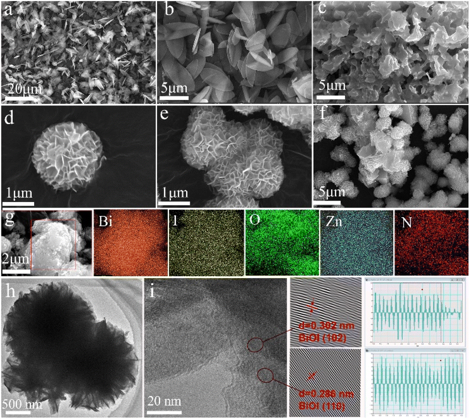
The structures of ZIF-L, N–ZnO, BiOI, and N–ZnO/BiOI-1 were characterized by SEM and TEM (Fig. 1). As shown in Fig. 1a and b, the ZIF-L crystal presented leaf-like morphology and a size of about 2 × 5 μm which were consistent with earlier literature.43 The ZIF-L phase structure of the product was shown using the XRD pattern, indicating that all peaks corresponded well with the simulated ZIF-L (Fig. S1†). Because of the low stability of ZIF-L, when it was sintered together, some of the morphology was likely retained. The flower-spherical structure was composed of nanosheets of bare BiOI in Fig. 1d and e, while the samples exhibited N–ZnO uniformly embedded in the flowery-spherical BiOI when compared to the as-synthesized complexes (Fig. 1f). Simultaneously, it was also evident that the N–ZnO could significantly prevent the agglomeration of the BiOI during the reaction and accelerate the separation of charge carrier. The EDS mapping (Fig. 2g) confirmed that the N–ZnO was successfully embedded in the BiOI, forming the hydrangea-like N–ZnO/BiOI-1 compounds. TEM images of the N–ZnO/BiOI-1 are displayed in Fig. 1h and i. It was found that the lattice spacings with an inter-planar of 0.300 and 0.286 nm were consistent with the (102) and (110) crystal planes of pristine BiOI, respectively. All of these certificated that the photocatalysts were successfully prepared.
 |
| | Fig. 1 (a and b) The SEM images of ZIF-L, (c) N–ZnO, (d and e) BiOI, and (f) N–ZnO/BiOI-1. (g) The EDS mapping of N–ZnO/BiOI-1. (h and i) The TEM images of N–ZnO/BiOI-1. | |
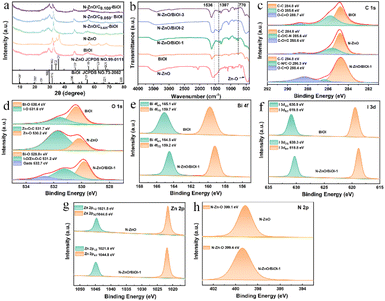 |
| | Fig. 2 (a) The XRD patterns of N–ZnO, BiOI, N–ZnO/BiOI-1, N–ZnO/BiOI-2, and N–ZnO/BiOI-3. (b) The FT-IR spectra of N–ZnO, BiOI, N–ZnO/BiOI-1, N–ZnO/BiOI-2 and N–ZnO/BiOI-3. (c–h) The XPS spectra of the N–ZnO, BiOI, and N–ZnO/BiOI-1 samples: C 1s, O 1s, Bi 4f, I 3d, Zn 2p, N 2p, respectively. | |
The crystalline structures of the BiOI, N–ZnO, and the as-prepared compounds were examined by XRD, and the results are shown in Fig. 2a. All the diffraction peaks of the pristine N–ZnO and BiOI were in accordance with standard ZnO (JCPDS NO.99-0111)41 and BiOI (JCPDS NO.73-2062)45,46 data, respectively. The diffraction peaks of N–ZnO/BiOI composites were similar to those of BiOI, illustrating that the synthesis process did not alter the pristine structure of BiOI. The lack of distinct N–ZnO peaks might be due to the low doping levels and similarity between the diffraction peaks of N–ZnO and BiOI, which obscured the N–ZnO peaks. Therefore, in order to further validate the presence of N–ZnO in these compounds, the FT-IR spectra were measured and are shown in Fig. 2b. In the case of bare BiOI, the bands in the range of 400–800 cm−1 were due to the Bi–O stretching mode, which included the asymmetrical stretching vibration of Bi–O at 770 cm−1.47,48 For N–ZnO, the band located at 1397 cm−1 and 1536 cm−1 were assigned to the stretching vibrational of the Zn–N and C![[double bond, length as m-dash]](https://www.rsc.org/images/entities/char_e001.gif) C bonds, respectively, while the bands between 400 and 600 cm−1 could be ascribed to the Zn–O bond.49 Noteworthy, the bands of the N–ZnO/BiOI composites not only include the characteristic bands of BiOI, but also the feature bands of the N–ZnO, indicating that the N–ZnO does successfully integrate with BiOI.
C bonds, respectively, while the bands between 400 and 600 cm−1 could be ascribed to the Zn–O bond.49 Noteworthy, the bands of the N–ZnO/BiOI composites not only include the characteristic bands of BiOI, but also the feature bands of the N–ZnO, indicating that the N–ZnO does successfully integrate with BiOI.
To further detect the surface electronic states of these samples, XPS spectra were carried out to achieve the target, as depicted in Fig. 2c–h. The binding energy of the XPS spectra was calibrated by the C 1s (284.8 eV). The high-resolution C 1s spectrum of N–ZnO/BiOI-1 showed binding energies for C–C (284.8 eV), C–O/CN (286.3 eV), and OCO (288.4 eV), respectively (Fig. 2c). The O 1s spectrum of N–ZnO/BiOI-1 is shown in Fig. 2d, with three fitting peaks at 529.8, 531.2, and 532.7 eV ascribed to Bi–O, I–O/Zn–O–C and the surface adsorbed oxygen (O ads),50 respectively. As shown in Fig. 2e, the Bi 4f XPS spectra of N–ZnO/BiOI-1 expressed two right-shifted peaks at Bi 4f5/2 (164.5 eV) and Bi 4f7/2 (159.2 eV) which could be ascribed to Bi3+.51,52 The I 3d spectrum of composites was depicted in Fig. 2f, with two peaks at 630.9 and 619.5 eV assigned to I 3d3/2 and I 3d5/2, respectively, which were states of I−1.53Fig. 2g shows that Zn 2p could be divided into two peaks at 1021.8 and 1044.8 eV, which were attributed to Zn 2p1/2 and Zn 2p3/2, respectively.54Fig. 2h shows that Zn elements successfully hybridized with complexes. The results of the XPS further confirmed that the N–ZnO/BiOI-1 complexes were successfully prepared.
As shown in Fig. S2a,† the N2 adsorption and desorption isotherms are used to examine the particular surface areas. According to the result, BiOI and N–ZnO/BiOI-1 exhibit type IV adsorption–desorption isotherms with an H3 hysteresis loop, and N–ZnO expresses type II adsorption–desorption isotherms. These imply that the BiOI and N–ZnO/BiOI-1 are a porous structure, whereas N–ZnO has nearly no pores, which is in line with the findings in Fig. S2b.† Additionally, the specific surface areas and other related information of the catalysts are displayed in Table S1,† among which the specific surface areas of BOI, N–ZnO and N–ZnO/BiOI-1 are 55.648, 1.656 and 69.156 m2 g−1, respectively. Obviously, N–ZnO/BiOI-1 has the biggest specific surface area which is attributed to the addition of the N–ZnO that improves the stacking of nanosheets of BiOI. Consequently, there will be more active sites available and facilitate the adsorption of TCH, increasing the photocatalytic performance.
3.2 Optical and electrochemical properties
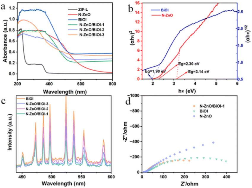
Fig. 3a shows the UV-vis diffuse absorption spectrum (UV-vis DRS) which was applied to understand the optical absorption of as-prepared samples. As this figure shows, these composites performed a similar light response to that of BiOI, demonstrating that BiOI is the vital component. The Kubelka–Munk theorem was used to obtain the optical band gaps (Eg), for instance, Fig. 3b shows that the band gaps of BiOI and N–ZnO were 1.90, 2.30, and 3.14 eV, respectively. The calculated formula is the Tauc plot (αhν = A (hν − Eg)n/2). Since the photocatalytic activity was connected to the separation and migration efficiency of photogenerated carriers, photoluminescence (PL) spectroscopy and electrochemical impedance spectroscopy (EIS) were utilized to investigate carrier recombination. The PL spectra of these products are shown in Fig. 3c, and it was obvious that N–ZnO/BiOI-1 had the lowest PL intensity, showing that the sample had a higher carrier separation efficiency. Fig. 3d demonstrates that, in accordance with the PL spectra, the N–ZnO/BiOI-1 had the smallest arc radius, the lowest interfacial charge transfer impedance, and the maximum charge-carrier separation efficiency.
 |
| | Fig. 3 (a) UV-vis spectra of different photocatalysts. (b) The converted Tauc plot versus photo energy. (c) The PL spectra of the photocatalysts. (d) The EIS spectra of N–ZnO, BiOI, and N–ZnO/BiOI-1 composite materials. | |
3.3 Photocatalytic degradation
3.3.1 Effects of the complexes with different contents.
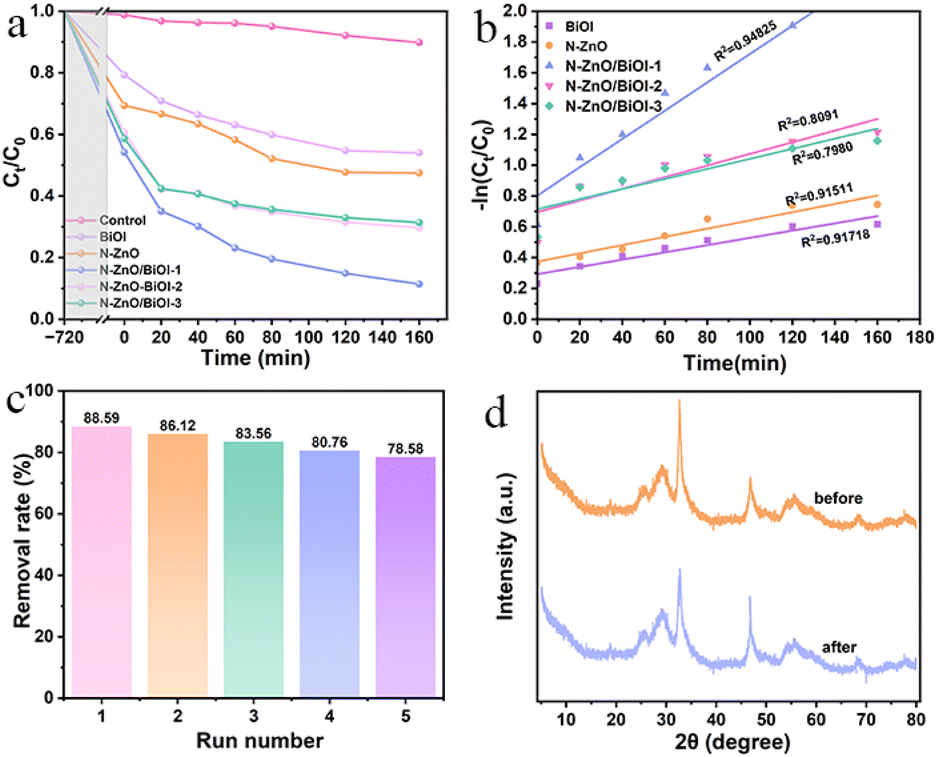
Adsorption is the first important step in photocatalytic degradation, and in the present study, it took 12 h to reach the adsorption equilibrium. As shown in Fig. 4a, when the photocatalyst dosage was 20 mg, the concentration of TCH was 10 mg L−1 and natural pH conditions were evaluated for the TCH degradation rate. Obviously, the degradation of TCH was negligible for the experiment without a catalyst via a blank experiment. After adding the as-synthesized products, it was observed that the photocatalytic degradation performance of composites had been significantly improved compared with bare BiOI and N–ZnO. To be specific, the N–ZnO/BiOI-1 manifested the most superior photocatalytic activity amongst all samples, with nearly 90% TCH degradation within 160 min and the maximum one (88.59%) was nearly 2 times as that of pristine BiOI (46.01%) and N–ZnO (52.59%), respectively. The photocatalytic degradation of TCH over all samples followed a pseudo-first-order kinetic model, the fitting diagram is shown in Fig. 4b, and clearly, the kinetic rate of N–ZnO/BiOI-1 was the highest (Table S2†).
 |
| | Fig. 4 (a) The photocatalytic performance of N–ZnO/BiOI-X. (b) The fitting curve by a quasi-first-order reaction. (c) The cycling runs. (d) The XRD patterns of fresh and used samples. | |
3.3.2 Effects of the pH.
Fig. S3a† shows that the influence of pH on TCH degradation under the conditions of the dosage was 20 mg and the concentration of the TCH was 10 mg L−1. It was obviously that the degradation rate was faster when pH = 9 than the other pH, achieving 91.8% within 160 min. By contrast, after dark adsorption for 160 min, the degradation rate of pH = 3, pH = 4.8 (nature), pH = 5, and pH = 7 was 83.04%, 88.59%, 77.52% and 86.76%, respectively. It could be concluded that since there was no significant difference in the degradation effect by pH, the experiments were conducted at natural pH conditions.
3.3.3 Effects of photocatalyst dosage.
Fig. S3b† demonstrates the influence of different photocatalyst dosages on TCH degradation under the condition of the pH was 4.8 (nature) and the concentration of TCH was 10 mg L−1. Apparently, when the amount of photocatalyst delivery was 20 mg, the degradation rate exhibited superior performance. This could be interpreted that the number of photogenerated carriers and more reactive sites could be provided which would be a benefit for improving photocatalytic efficiency by increasing the dosage of the photocatalyst. Nevertheless, when the dosage was added to a certain extent, the photocatalytic degradation did not increase as expected but rather decreased. This was probably due to the increased turbidity of the solution, which lowered light transmission and had a negative effect.
3.3.4 Effects of TCH initial concentration.
Fig. S3c† displays that the influence of different photocatalyst concentrations on TCH degradation under the conditions of the pH was 4.8 (nature) and the dosage was 20 mg. It could be deduced that the rate of photocatalytic degradation was greatest when the concentration of TCH was 10 mg L−1, which might be explained by the fact that when increasing concentrations of solutions became available, more intermediates were formed and accumulated. Therefore, it would compete with the active oxidizing substances produced in the photocatalytic system and inhibit the degradation of THC.
3.4 Reusability and stability
In practical applications, another important measure was the lifetime of the catalyst. As shown in Fig. 4c, the photocatalytic efficiency of N–ZnO/BiOI-1 to TCH was 88.59%, 86.12%, 85.04%, 80.76%, and 78.58%, respectively, which slightly decreased after five cycle runs, confirming the outstanding recyclability for the N–ZnO/BiOI-1 photocatalyst. Meanwhile, Fig. 4d depicts the XRD patterns after five cycles of testing, and only minor differences in peak intensity were observed in the XRD of N–ZnO/BiOI-1 before and after the experiment. To sum up, the N–ZnO/BiOI-1 composites could be considered to have good recyclability and stability.
3.5 Photocatalytic degradation mechanism
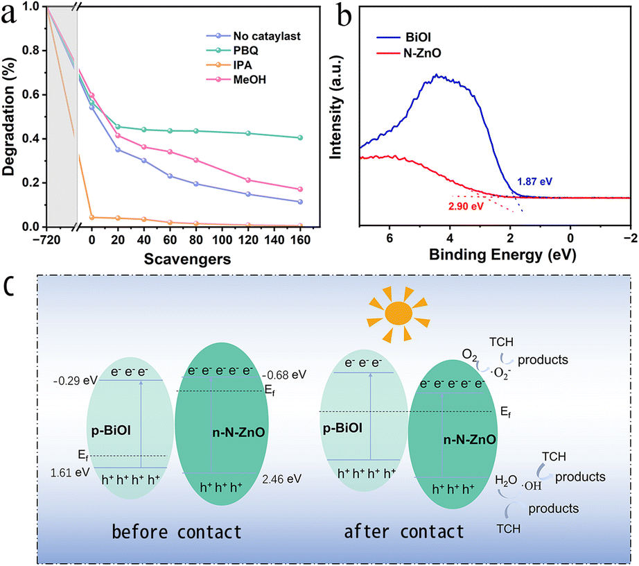
To determine the main active species produced, reactive species trapping experiments for photocatalytic degradation of tetracycline were performed on N–ZnO/BiOI hybrids. In this regard, p-Benzoquinone (PBQ), iso-propyl alcohol (IPA), and methanol (MeOH) were chosen as the scavengers for ·O2−, ·OH and h+, respectively. According to Fig. 5a, the degradation efficiency of tetracycline decreased with the addition of MeOH and PBQ, from 88.59% to 82.92 and 59.54%, respectively, suggesting that ·O2− played a key role in the photocatalytic reduction of TCH. Furthermore, when IPA was added to the degradation studies, it was shown that IPA could swiftly capture ·OH, and effectively promote the degradation efficiency.
 |
| | Fig. 5 (a) Reactive species trapping experiments (b) the VB-XPS of BiOI and N–ZnO. (c) The possible mechanism for TCH degradation. | |
The valence band (VB)-XPS of BiOI and N–ZnO is shown in Fig. 5b, and the VB potentials (EVB) of the BiOI and N–ZnO are 1.37 and 2.46 eV (vs. a normal hydrogen electrode [NHE], based on the following formula),55,56 respectively. Therefore, the conduction band (CB) potentials (ECB) were −0.53 and −0.68 eV for BiOI and N–ZnO, respectively.
where the electron work function (
Φ) of the used XPS analyzer is 4.00 eV, ENHE and EVBM indicate the potentials of an NHE and the VB maximum (VBM), respectively.
As shown in Fig. 5b, the degradation mechanism could be inferred from the experimental findings. Electrons can hop from the valence band (VB) to the conduction band (CB) under simulated sunlight, filling the CB with free electrons and leaving holes in the VB. In this experiment, the semiconductors of N–ZnO and BiOI are n- and p-type, respectively, leading to different Fermi levels. Therefore, when the N–ZnO and BiOI come into contact, the interfacial charge transfer occurs,41,46 resulting in the formation of the inner electric field.57–59 The electrons on the CB of N–ZnO will recombine with the holes on the VB of BiOI due to the action of the built-in electric field, and thus the holes on the VB of the N–ZnO can directly oxidize degradation TCH; simultaneously, the electrons can react with H2O to form ·OH radicals. Additionally, the electrons on the CB of N–ZnO are lower than O2/·O2− (−0.330 eV vs. NHE),60 suggesting that the e−can react with oxygen to generate ·O2− radicals.61 and react with TCH to form the harmless products. The potential degradation pathways are illustrated below:
| e−/CB (N–ZnO) + O2 → ·O2− |
| ·O2− + Dye → CO2 + H2O + inorganic ions |
| h+/VB (N–ZnO) + H2O →·OH + OH− |
| ·OH + Dye → CO2 + H2O + inorganic ions |
| h++ Dye → CO2 + H2O + inorganic ions |
The UV-vis absorption spectra are recorded to analyze the products at different times of photocatalytic degradation As demonstrated in Fig. S4,† with the increase of reaction time, the typical absorption peak intensity of TCH at 357 nm fell dramatically when the illumination time extended to 160 min, which indicates that TCH is effectively degraded.
4 Conclusions
In summary, an efficient photocatalytic N–ZnO/BiOI composite had been successfully prepared via a simple hydrothermal synthetic strategy. The structure and chemical composition of these as-synthesized samples were studied by SEM, TEM, XPS, and FT-IR. At the same time, the electrochemical properties were evaluated by PL and EIS. Next, the effect of different conditions on the experiment was examined, such as the amount of N–ZnO doping, solution pH, catalyst delivery, and solution concentration. Through the experiments, it could be seen that under natural pH conditions with a solution concentration of 10 mg L−1 and a dose of 10 mg, N–ZnO/BiOI-1 exhibited the most superior photocatalytic degradation ability which could degrade 88.4% in 160 min. The radical trapping experiments showed that ·O2− radicals and h+ radicals were the important reactive species in the photocatalytic degradation of TCH. Overall, this highly efficient photocatalytic N–ZnO/BiOI composite have provided an effective aid for the development of new and efficient water treatment technologies.
Author contributions
X. C., Z. L. S. D., and B. L. conceived the project. Z. L. S. D., and B. L supervised the project. X. C. and Z. L. performed the experiments and characterization. X. C., Z. L. and S. D., co-wrote the manuscript. All authors discussed the results and commented on the manuscript.
Conflicts of interest
There are no conflicts to declare.
Acknowledgements
This work was supported by the National Natural Science Foundation of China (81970976 and 22076071) and also by the Foundation for Young Doctors from the Education Department of Gansu Province (2022QB-086).
Notes and references
- Q. Chen, X. Guo, G. Hua, G. Li, R. Feng and X. Liu, Environ. Pollut., 2017, 220, 1301–1310 CrossRef CAS PubMed.
- Z. Cao, Y. Jia, Q. Wang and H. Cheng, Appl. Clay Sci., 2021, 212, 106213 CrossRef CAS.
- P. Dhandapani, A. A. Prakash, M. S. AlSalhi, S. Maruthamuthu, S. Devanesan and A. Rajasekar, Mater. Chem. Phys., 2020, 243, 122619 CrossRef CAS.
- P. Parthipan, L. Cheng, A. Rajasekar, M. Govarthanan and A. Subramania, Environ. Res., 2021, 196, 110983 CrossRef CAS PubMed.
- M. Khraisheh, J. Kim, L. Campos, A. A. H. Al-Muhtaseb, A. Al-Hawari, M. Al Ghouti and G. M. Walker, J. Ind. Eng. Chem., 2014, 20, 979–987 CrossRef CAS.
- W. Li, J. Cao, W. Xiong, Z. Yang, S. Sun, M. Jia and Z. Xu, Chem. Eng. J., 2020, 392, 124844 CrossRef CAS.
- Y. Cheng, H. He, C. Yang, G. Zeng, X. Li, H. Chen and G. Yu, Biotechnol. Adv., 2016, 34, 1091–1102 CrossRef CAS PubMed.
- M. Jia, Z. Yang, H. Xu, P. Song, W. Xiong, J. Cao, Y. Zhang, Y. Xiang, J. Hu, C. Zhou, Y. Yang and W. Wang, Chem. Eng. J., 2020, 388, 124388 CrossRef CAS.
- R. Liu, D. Zuo and C. Tan, J. Alloys Compd., 2022, 911, 165023 CrossRef CAS.
- C. Lai, D. Ma, H. Yi, M. Zhang, F. Xu, X. Huo, H. Ye, L. Li, L. Yang, L. Tang and M. Yan, Sep. Purif. Technol., 2023, 306, 122546 CrossRef CAS.
- F. Xu, C. Lai, M. Zhang, D. Ma, L. Li, S. Liu, X. Zhou, H. Yan, N. Wang, M. Xu, L. Qin and H. Yi, Sep. Purif. Technol., 2023, 308, 122829 CrossRef CAS.
- A. K. P. D. Savio, J. Fletcher, K. Smith, R. Iyer, J. M. Bao and F. C. Robles Hernández, Appl. Catal., B, 2016, 182, 449–455 CrossRef CAS.
- J. Li, X. a. Dong, Y. Sun, W. Cen and F. Dong, Appl. Catal., B, 2018, 226, 269–277 CrossRef CAS.
- T. Jia, J. Wu, J. Song, Q. Liu, J. Wang, Y. Qi, P. He, X. Qi, L. Yang and P. Zhao, Chem. Eng. J., 2020, 396, 125258 CrossRef CAS.
- Y.-C. Wu, Y.-C. Chaing, C.-Y. Huang, S.-F. Wang and H.-Y. Yang, Dyes Pigm., 2013, 98, 25–30 CrossRef CAS.
- Y. Tong, C. Zheng, W. Lang, F. Wu, T. Wu, W. Luo and H. Chen, Mater. Des., 2017, 122, 90–101 CrossRef CAS.
- K. Zhang, C. Liu, F. Huang, C. Zheng and W. Wang, Appl. Catal., B, 2006, 68, 125–129 CrossRef CAS.
- P. Gao, Z. Zhang, L. Feng, Y. Liu, Z. Du and L. Zhang, Chem. Eng. J., 2021, 426, 130764 CrossRef CAS.
- H. Huang, K. Xiao, T. Zhang, F. Dong and Y. Zhang, Appl. Catal., B, 2017, 203, 879–888 CrossRef CAS.
- M. Sun, Q. Wei, Y. Shao, B. Du, T. Yan, L. Yan and D. Li, Appl. Catal., B, 2018, 233, 250–259 CrossRef CAS.
- P. Gao, Z. Yin, L. Feng, Y. Liu, Z. Du, Z. Duan and L. Zhang, Environ. Res., 2020, 185, 109468 CrossRef CAS PubMed.
- X. Y. Kong, W. Q. Lee, A. R. Mohamed and S.-P. Chai, Chem. Eng. J., 2019, 372, 1183–1193 CrossRef CAS.
- C. Wang, Y. Li, L. Huang, L. Yang, H. Wang, J. Liu, J. Liu, Z. Song and L. Huang, Chem. Eng. J., 2021, 411, 128505 CrossRef CAS.
- J. Bai, J. Sun, X. Zhu, J. Liu, H. Zhang, X. B. Yin and L. Liu, Small, 2020, 16, e1904783 CrossRef PubMed.
- L. Ye, X. Jin, X. Ji, C. Liu, Y. Su, H. Xie and C. Liu, Chem. Eng. J., 2016, 291, 39–46 CrossRef CAS.
- X. J. Wen, C. G. Niu, L. Zhang and G. M. Zeng, Dalton Trans., 2017, 46, 4982–4993 RSC.
- A. Das, M. Patra, M. Kumar P, M. Bhagavathiachari and R. G. Nair, J. Alloys Compd., 2021, 858, 157730 CrossRef CAS.
- M. Liu, J. Li, R. Bian, X. Wang, Y. Ji, X. Zhang, J. Tian, F. Shi and H. Cui, J. Alloys Compd., 2022, 905, 164025 CrossRef CAS.
- A. Wang, J. Ni, W. Wang, X. Wang, D. Liu and Q. Zhu, J. Hazard. Mater., 2022, 426, 128106 CrossRef CAS PubMed.
- L. Gu, X. Hou, Y. Lei, S. Gou, X. Yang, W. He and Z. Zheng, J. Alloys Compd., 2022, 904, 163934 CrossRef CAS.
- D. P. Sebuso, A. T. Kuvarega, K. Lefatshe, C. K. King’ondu, N. Numan, M. Maaza and C. M. Muiva, J. Alloys Compd., 2022, 900, 163526 CrossRef CAS.
- H. Wang, Y. Liang, L. Liu, J. Hu, P. Wu and W. Cui, Appl. Catal., B, 2017, 208, 22–34 CrossRef CAS.
- J. Liang, Q. Shan, T. Liu, W. Liang, X. Zhang, W. Qi, H. Tan, S. Du, L. Qian, Z. Li and X. Chen, Electrochim. Acta, 2021, 394, 139137 CrossRef CAS.
- S. Yuan, L. Feng, K. Wang, J. Pang, M. Bosch, C. Lollar, Y. Sun, J. Qin, X. Yang, P. Zhang, Q. Wang, L. Zou, Y. Zhang, L. Zhang, Y. Fang, J. Li and H. C. Zhou, Adv. Mater., 2018, 30, e1704303 CrossRef PubMed.
- M. I. Hossain, J. D. Cunningham, T. M. Becker, B. E. Grabicka, K. S. Walton, B. D. Rabideau and T. G. Glover, Chem. Eng. Sci., 2019, 203, 346–357 CrossRef CAS.
- J. Liang, T. Liu, Y. Li, W. Liang, X. Zhang, L. Qian, Z. Li and X. Chen, Cell Rep. Phys. Sci., 2022, 3, 100769 CrossRef CAS.
- J. Lee, O. K. Farha, J. Roberts, K. A. Scheidt, S. T. Nguyen and J. T. Hupp, Chem. Soc. Rev., 2009, 38, 1450–1459 RSC.
- H. Furukawa, N. Ko, Y. B. Go, N. Aratani, S. B. Choi, E. Choi, A. Ö. Yazaydin, R. Q. Snurr, M. O'Keeffe, J. Kim and O. M. Yaghi, Science, 2010, 329, 424–428 CrossRef CAS PubMed.
- J. Tang, R. R. Salunkhe, J. Liu, N. L. Torad, M. Imura, S. Furukawa and Y. Yamauchi, J. Am. Chem. Soc., 2015, 137, 1572–1580 CrossRef CAS PubMed.
- H. Zeng, G. Duan, Y. Li, S. Yang, X. Xu and W. Cai, Adv. Funct. Mater., 2010, 20, 561–572 CrossRef CAS.
- C. Zhang, M. Jia, Z. Xu, W. Xiong, Z. Yang, J. Cao, H. Peng, H. Xu, Y. Xiang and Y. Jing, Chem. Eng. J., 2022, 430, 345603 Search PubMed.
- L. Sun, Q. Shao, Y. Zhang, H. Jiang, S. Ge, S. Lou, J. Lin, J. Zhang, S. Wu, M. Dong and Z. Guo, J. Colloid Interface Sci., 2020, 565, 142–155 CrossRef CAS PubMed.
- K. Yang, S. Hu, Y. Ban, Y. Zhou, N. Cao, M. Zhao, Y. Xiao, W. Li and W. Yang, Sci. Bull., 2021, 66, 1869–1876 CrossRef CAS PubMed.
- T. Ke, S. Shen, K. Yang and D. Lin, Nanotechnology, 2020, 31, 345603 CrossRef CAS PubMed.
- B. Li, X. Chen, T. Zhang, S. Jiang, G. Zhang, W. Wu and X. Ma, Appl. Surf. Sci., 2018, 439, 1047–1056 CrossRef CAS.
- J. Wang, S. Li, K. Yang, T. Zhang, S. Jiang, X. Li and B. Li, ACS Appl. Nano Mater., 2022, 5, 6736–6749 CrossRef CAS.
- W. Li, Q. Wang, L. Huang, Y. Li, Y. Xu, Y. Song, Q. Zhang, H. Xu and H. Li, RSC Adv., 2015, 5, 88832–88840 RSC.
- J. Xiong, H.-Y. Zeng, S. Xu, J.-F. Peng, F.-Y. Liu and L.-H. Wang, J. Mater. Sci. Technol., 2022, 118, 181–189 CrossRef.
- C. Hu, X. Hu, R. Li and Y. Xing, J. Hazard. Mater., 2020, 385, 121599 CrossRef CAS PubMed.
- H. Yu, J. Li, Y. Zhang, S. Yang, K. Han, F. Dong, T. Ma and H. Huang, Angew. Chem., Int. Ed. Engl., 2019, 58, 3880–3884 CrossRef CAS PubMed.
- Y. Yang, Z. Zeng, C. Zhang, D. Huang, G. Zeng, R. Xiao, C. Lai, C. Zhou, H. Guo, W. Xue, M. Cheng, W. Wang and J. Wang, Chem. Eng. J., 2018, 349, 808–821 CrossRef CAS.
- M. Bharti, A. Singh, G. Saini, S. Saha, A. Bohra, Y. Kaneko, A. K. Debnath, K. P. Muthe, K. Marumoto, D. K. Aswal and S. C. Gadkari, J. Power Sources, 2019, 435, 226758 CrossRef CAS.
- Y. Wang, K. Deng and L. Zhang, J. Phys. Chem. C, 2011, 115, 14300–14308 CrossRef CAS.
- Y. Liu, H. Liu, H. Zhou, T. Li and L. Zhang, Appl. Surf. Sci., 2019, 466, 133–140 CrossRef CAS.
- J. Wang, P. Li, Y. Wang, Z. Liu, D. Wang, J. Liang and Q. Fan, Adv. Sci., 2022, e2205542 Search PubMed.
- H. Yu, R. Shi, Y. Zhao, T. Bian, Y. Zhao, C. Zhou, G. I. N. Waterhouse, L.-Z. Wu, C.-H. Tung and T. Zhang, Adv. Mater., 2017, 29, 1605148 CrossRef PubMed.
- Q. Xu, L. Zhang, B. Cheng, J. Fan and J. Yu, Chem, 2020, 6, 1543–1559 CAS.
- P. Xia, S. Cao, B. Zhu, M. Liu, M. Shi, J. Yu and Y. Zhang, Angew. Chem., Int. Ed. Engl., 2020, 59, 5218–5225 CrossRef CAS PubMed.
- L. Zhang, J. Zhang, H. Yu and J. Yu, Adv. Mater., 2022, 34, e2107668 CrossRef PubMed.
- A. Kumar, A. Rana, G. Sharma, M. Naushad, A. H. Al-Muhtaseb, C. Guo, A. Iglesias-Juez and F. J. Stadler, ACS Appl. Mater. Interfaces, 2018, 10, 40474–40490 CrossRef CAS PubMed.
- G. Wang, X. Ma, J. Liu, L. Qin, B. Li, Y. Hu and H. Cheng, Sci. Total Environ., 2020, 741, 140192 CrossRef CAS PubMed.
|
| This journal is © The Royal Society of Chemistry 2023 |
Click here to see how this site uses Cookies. View our privacy policy here. 
 Open Access Article
 This Open Access Article is licensed under a Creative Commons Attribution-Non Commercial 3.0 Unported Licence
 b,
Lei
Gao
a,
Kejin
Shao
c,
Zhan
Li
b,
Lei
Gao
a,
Kejin
Shao
c,
Zhan
Li