DOI:
10.1039/D2NA00850E
(Paper)
Nanoscale Adv., 2023,
5, 3279-3286
Generalised analytical model of the transition power densities of the upconversion luminescence and quantum yield
Received
25th November 2022
, Accepted 4th April 2023
First published on 7th April 2023
Abstract
The quantum yield (QY) evaluation of upconverting nanoparticles (UCNPs) is an essential step in the characterisation of such materials. The QY of UCNPs is governed by competing mechanisms of populating and depopulating the electronic energy levels involved in the upconversion (UC), namely linear decay rates and energy transfer rates. As a consequence, at low excitation, the QY excitation power density (ρ) dependence obeys the power law ρn−1, where n represents the number of absorbed photons required for the emission of a single upconverted photon and determines the order of the energy transfer upconversion (ETU) process. At high power densities, the QY transits to a saturation level independent of the ETU process and the number of excitation photons, as a result of an anomalous power density dependence present in UCNPs. Despite the importance of this non-linear process for several applications (e.g., living tissue imaging and super-resolution-microscopy), little has been reported in the literature regarding theoretical studies to describe the UC QY, especially for ETUs with order higher than two. Therefore, this work presents a simple general analytical model, which introduces the concept of the transition power density points and QY saturation to characterise the QY of an arbitrary ETU process. The transition power density points determine where the power density dependence of the QY and the UC luminescence changes. The results provided in this paper from fitting the model to experimental QY data of a Yb–Tm codoped β-UCNP for 804 nm and 474 nm emissions (ETU2 and ETU3 processes, respectively) exemplify the application of the model. The common transition points found for both processes were compared to each other showing strong agreement with theory, as well as, compared to previous reports when possible.
1 Introduction
In the last few decades, upconverting nanoparticles (UCNPs) have been extensively studied due to their unique ability to convert low-energy photons to high-energy photons, an anti-Stokes non-linear process involving multi-photon absorption followed by the emission of a single photon with the total absorbed energy.1–3 The upconversion luminescence (UCL) non-linearity is a unique property responsible for a breakthrough in super-resolution microscopy, where researchers achieved sub 70 nm imaging resolution utilising the giant non-linear response found in some UCNPs.4–7 From clean energy to biophotonics, UCNPs have also been successfully applied to light harvesting,8,9 photodynamic therapy (PDT),10 diffuse optical imaging,11 optogenetics,12,13 biosensors,14 and temperature sensing.15,16 Despite their potential, the quantum yield (QY) of UCNPs remains low, especially at low excitation power densities required for biological applications.17 The internal quantum yield (iQY) is often used as a figure of merit to characterise UCNPs, and is defined as the ratio of the number of emitted photons to the number of absorbed ones.18–20 At low excitation power densities the non-linear behaviour of UCL is more pronounced and, as a consequence, the iQY is power density dependent,20–23 which adds further complexities to the evaluation of their efficiency. An accurate iQY evaluation is crucial for the development of optimal UCNPs, although, analytical and modelling studies on the excitation power density dependence of iQY are astonishingly scarce.22
The most efficient UCNPs have a sensitizer ion that strongly absorbs near-infrared (NIR) photons and transfers its energy to an activator ion via a phonon through the lattice of a host matrix.3 This energy transfer upconversion (ETU) process excites the electrons from the ground state to an nth excited state of the activators in a sequence of steps involving long-living intermediate states.24 When the electrons relax radiatively from the excited state |n〉 to lower states, an ETU process of order n (ETUn) is completed and a single photon is emitted with higher energy.1–3,25 At low power densities the non-linear UCL is proportional to ρn, where n represents the number of absorbed photons involved in the process and ρ is the uniform excitation power density of irradiated UCNPs. As the excitation power density is increased, the UCL transits to regimes of power density dependence with an exponent lower than n, and eventually reaches linearity, i.e. ρ1. The UCL of upconverting micro-particles tends to saturate after reaching linearity as the power density is further increased.26,27 Unlikely, the UCL of UCNPs typically does not show saturation, regardless of the number of excitation photons and number of energy transfers involved.21,28 This behaviour seen in UCNPs, named as anomalous power (density) dependence for the first time by Suyver et al., has been extensively observed experimentally as shown in the literature.20–22,27–33 Yet, analytical studies exploring the phenomenon are nonexistent, especially with regard to the different power density regimes and the thresholds between them. The delimitation of the regimes has never been formally defined before, and thus far is based on subjective assessment in the literature; the authors refer to the ranges of non-linearity and linearity as being at the “low” and “high power densities”, respectively.18,21,22,27,28,34,35 These subjective terms can well describe the UCL behaviour qualitatively, although a quantitative method is necessary for accurate characterisation, especially in applications where precise tuning of the UCL dynamics is crucial.36 Recently, Liu et al., while studying the ETU2 of a NIR UCL, have introduced the concept of the “balancing power density” as the transition point where the iQY is exactly half of its maximum QY value (the “QY saturation” level), which is reached at the linear regime of the UCL.22 The balancing power density was the first concept of a quantitative parameter to define the threshold between the non-linear and linear regimes of ETU2 processes, highlighting its importance. In addition, their model reduced a complex power density dependent system, with numerous energy transfer and linear decay rates, to a simple equation with two variables: the balancing power density point and the QY saturation. The model proposed by the authors was based on two key studies21,28 using an elegant but simple rate equation model to describe the population densities of the energy states involved in the UC. Later on, their model was utilised in the implementation of a beam-profile compensation on experimental QY and to demonstrate the need of the compensation for an accurate evaluation of the iQY.20,23 Apart from Liu et al.'s study on ETU2, no study has been conducted on higher ETU processes. A precise modelling of the UCL and iQY is of particular importance to the optimisation of application-specific UCNPs. Therefore, this work presents a general analytical model for an ETU process of arbitrary order, and includes a detailed analysis of the how a transition power density point, such as the balancing power density, affects ETU processes of higher order. Applying the model to an ETU2 process, the found transition power density points were compared to the balancing point proposed by Liu et al. In addition, the distinct power density behaviour of UCNPs and that of their bulk counterparts are discussed in terms of their iQY saturation and transition power density points. Experimental results, supporting the findings, and exemplifying the application of the model to the characterisation of UCNPs, are presented for the 804 nm and 474 nm emissions (ETU2 and ETU3 processes, respectively) of a Yb–Tm codoped β-UCNP.
2 Materials and methods
2.1 Sample characterisation
β-NaYF4:YbTm core–shell UCNPs with multiple emission wavelengths dispersed in toluene, purchased from Creative Diagnostics, were chosen for the experiments. Morphology, dispersion and size were characterised with a scanning transmission electron microscope (STEM). The sample was drop-cast over 5 mm silicon and images were acquired in the transmission mode. For the emission spectra and QY measurements a 500 mW CW 976 nm excitation laser diode (Thorlabs – BL976-PAG500), controlled by a digital driver (Thorlabs – CLD1015) was utilised to irradiate the sample. The excitation beam was shaped to a Gaussian profile with 302 μm diameter taken as full-width-at-half-maximum. The power densities of the excitation were calculated by the ratio of power to the area of the cross-section of the beam. The emission spectra of the sample were acquired for a few power densities ranging from 20 W cm−2 to 100 W cm−2 with a commercial spectrometer (Ocean Optics – QEPRO-FL) attached to the emission arm at 90° to the excitation path of a QY system built in the lab, which is reported elsewhere.35 The QY system was calibrated with two commercial organic dyes: a NIR dye diluted in ethanol (Dyomics – DY-781-01) with an emission peak at 800 nm and known QY of 12.4%, obtained according to a standard protocol;20,23,31 and a blue dye diluted in ethanol (Dyomics – DY-415-01) with an emission peak at 467 nm and QY of 20.2% characterised by the manufacturer. The calibration at these specific wavelengths accounts for the wavelength dependence of the APD sensitivities, and these dyes were chosen to match their emission wavelength with the UCNP emission wavelengths that were characterised with the QY system. The sample of UCNPs was prepared and characterised according to the process recently reported in the literature.20 Experimentally, the iQYs were obtained according to the definition, which written in terms of wavelengths and power is given by eqn (1),| |  | (1) |
where Lλem [W] is the UCL for the wavelength of emission λem [nm], Pa [W] is the total absorbed power, and λex [nm] is the excitation wavelength, 976 nm.
The iQY evaluation was conducted for the 804 nm and the 474 nm UCL peaks, which were measured simultaneously at two avalanche photodiodes (APDs) (Thorlabs – APD410A and APD440A2, respectively) attached to the QY system. The emission wavelengths, selected for the characterisation, were chosen accordingly as they were the most intense emission peaks for these UCNPs, and because, they arise from two distinct ETU processes (ETU2 and ETU3 processes). In addition, the NIR emission is widely used in most of the applications in the biophotonic field because of its high penetration depth in living tissues,17,37,38 while the blue UC emission of UCNPs has shown promising utilisation to trigger neurons for less invasive techniques in optogenetics.13,39,40 Despite the beam-profile-compensation to be essential for the iQY characterisation, its mathematical derivation would deviate the focus of this work. Therefore, for the purpose of exemplifying the theoretical findings and keeping the message clear in this paper, the beam-profile-compensation was not accounted for in the experimental results.
3 Results and discussion
3.1 A general theoretical model
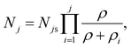
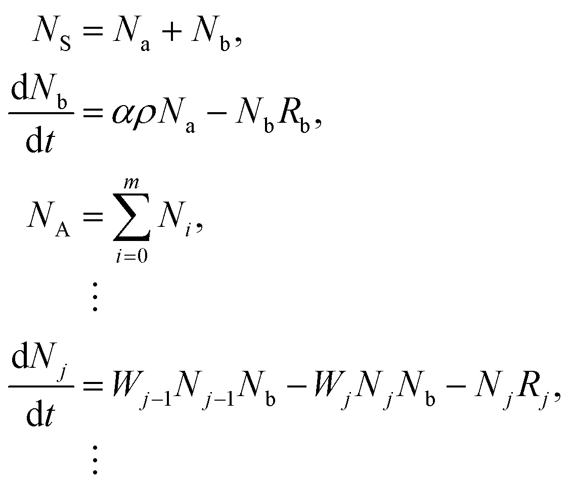
The general model proposed here in its simplest form comprises a two-level sensitizer (S) and an activator (A) with an arbitrary number of energy levels m larger than two, as shown in Fig. 1. The electrons from the sensitizer's ground state |a〉 are pumped to the excited energy level |b〉 using an excitation source with power density ρ [W cm−2] and natural frequency νex [Hz]. The probability of a photon to be absorbed is given by the sensitizer's cross-section area σS [cm2]. As the sensitizer relaxes to the ground state |a〉 with a constant rate Rb [s−1], phonons propagate through the lattice carrying energy until it encounters an activator and transfers the energy to the ions, exciting them from their current state |j − 1〉 to the next higher state |j〉. The energy transfer (ET) is the key process that determines the dynamics of the populating and depopulating mechanisms of the UC energy states.24 Thus, the model considers that any energy state |j〉 is populated only by ET with a constant rate Wj−1 [s−1], and cross-relaxation is neglected. The depopulation of a |j〉 state occurs via two mechanisms, as such, a linear decay to the activator's ground state |0〉 with a decay constant rate Rj [s−1], and an excitation to the next higher energy state |j + 1〉 by ET. The set of population density equations and their rate equations that encapsulates the concept of the proposed model is given by eqn (2),| |  | (2) |
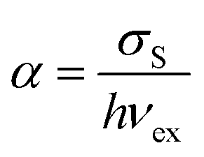
where Nj [cm−3] is the population density of an arbitrary |j〉 state, for j ∈ {1, 2, 3, …, m}; Na [cm−3], and Nb [cm−3] are the population densities of the energy states |a〉 and |b〉, respectively; NS [cm−3], and NA [cm−3] represent the total electronic density of the sensitizers and activators, respectively; and α [cm2 J−1] is the sensitizer's cross-section σS divided by Planck's constant ℏ [J s] times the natural frequency of the excitation photons νex, eqn (3).| |  | (3) |
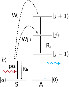 |
| | Fig. 1 Simplified energy levels scheme representing a two-level sensitizer (S) and an activator (A) with an arbitrary number of energy levels. The diagram represents the sensitizer's electrons being excited by ground state absorption and subsequent multiple energy transfers to equally spaced energy levels present in the activator (A) ion. Any |j〉 excited state (i.e. j > 0) is populated and depopulated by mechanisms of the same nature, and if j is equal to 1, the state |j − 1〉 coincides with the ground state |0〉. The curly arrows represent the excitation photon on the left, and the emitted photon on the right, whereas the arrows pointing up (down) represent the electronic transitions to a higher (lower) energy state. The dashed lines correspond to the energy transfers between the ions. | |
Solving the equations for the steady states, the population densities for the energy states |b〉 and the |j〉's are given by eqn (4) and (5), respectively.
| |  | (4) |
| | 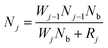 | (5) |
Being |j〉 an arbitrary state, one can prove that eqn (5) is also a solution for the state |j − 1〉 by the principle of finite induction. Therefore, the population density for a |j〉 state can be represented in terms of the population density of the ground state of the activators N0 [cm−3] by replacing recursively the solutions of all the energy states lower than |j〉, i.e. Nj−1, Nj−2, …, N0, in eqn (5). The population density of the ground state barely changes during UC processes within the ranges of power densities utilised in most applications, and thus, N0 can be considered a constant of the order of magnitude of NA. Furthermore, the power density dependent solution is obtained by replacing Nb in eqn (5) by eqn (4). This solution is valid for the limit where ρ ≪ Rb/α (typically Rb/α > 5000 W cm−2 for a range of values of σS and Rb found in the literature41,42). Within this limit, the population density of the sensitizer's ground state Na is much larger than the population density of the excited state |b〉, Na ≫ Nb, and thus, Na can be considered a constant with the same order of magnitude of NS. Therefore, the simplified solution is given by eqn (6),
| |  | (6) |
where
Njs [cm
−3] is the saturated population density for the energy state |
j〉, given by
eqn (7), and
ρi [W cm
−2] defines the power density transition point corresponding to a state |
i〉 for
i ∈ {1, 2, …,
j}, given by
eqn (8),
| |  | (7) |
| |  | (8) |
where
W0 [s
−1] is the energy transfer rate responsible for the electronic excitation from the energy state |0〉 to the first excited state |1〉.
The population density saturation is reached at excitation power densities much higher than the constants ρi, where these transition constants can be neglected. A ρi constant determines the threshold where the slope of the population density versus the excitation power density in a double logarithmic scale for a particular |i〉 state transits from i to i − 1, as the excitation power density is increased. Notice that a particular transition point ρi influences the population density of its correspondent energy state |i〉 and the population densities of all the energy states above. However, it does not affect any energy state below it. For example, taking j equal to 1, the product in the solution of eqn (6) is reduced to a single element with the transition point ρ1. Now, taking j equal to 2, one can notice that the population density solution is dependent on the transition points ρ1 and ρ2. Thus, the constant ρ2 does not influence the state |1〉, although it influences the energy state |2〉. Considering the solutions for the energy states above |2〉, one can verify that ρ2 also affects all the higher energy states.
The iQY for the emitted photons originated from an energy state |j〉, ηj [−], is, by definition, the ratio of the number of emitted photons to the number of absorbed photons. The emitted photon density per second is proportional to the population density of this state multiplied by a constant factor Rradj [s−1] (which is the radiative decay rate from the energy state |j〉), and the density of absorbed photons per second is given by the product αNaρ. Thereby, the power density dependent iQY for each of these energy states is easily obtained as represented by eqn (9).
| | 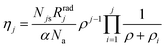 | (9) |
3.2 The power density limits and the anomalous power density dependence of UCNPs
At the limit where ρ ≪ ρi, ∀i ∈ {1, …, j}, the population density becomes proportional to ρj, and the iQY becomes proportional to ρj−1, obeying the power law observed experimentally.21,22,34 At the other extreme, where the limit ρ ≫ ρi, ∀i ∈ {1, …, j} applies, the model indicates that the population density of the states |j〉 reaches a saturation level, given by the constant Njs, and therefore the iQY is quenched. This effect has been observed for upconverting microparticles,26,27 although the typical behaviour of UCNPs indicates no saturation of the population densities at high power densities. Instead, the UCL of UCNPs exhibits linear power density dependence within this regime, i.e. ρ1, independent of the energy state or the order of the ETU process,20–22,27–33 as previously mentioned. Named as anomalous power dependence by Suyver et al.,21 this phenomenon is explained if one of the transition power density points is significantly large and had never been reached experimentally in UCNPs. Suyver et al. showed a few experimental examples of UCNPs with different sensitizers and activators for which the anomalous behaviour occurs for all the upconverting states including the energy state |1〉, i.e. the states related to the down conversion. This suggests that the ρ1 was never reached during their experiments, and therefore one can conclude that the highest transition point is in fact ρ1. Fig. 2 shows a schematic representation of the population densities, eqn (6), and iQY, eqn (9), for the UC of a four-level system in a double-logarithmic representation. The power density dependence of the regimes of each energy state is indicated in the plots. In this example, ρ1 is much larger than the other transition points. As a consequence, the population densities of all the energy states present linear power density dependence at power densities much higher than ρ2 and ρ3, yet much lower than ρ1. Having ρ1 much larger than the other transition points allows the linearity of all the energy states to be observed over a wide range of excitation power densities without any significant change in the slope of the experimental UCL curves, which represent the anomalous power density dependence observed in UCNPs.
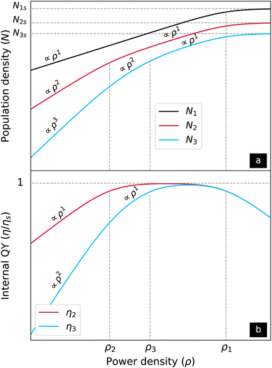 |
| | Fig. 2 Schematic representation of the (a) population densities, and (b) the iQYs versus the excitation power density in a double logarithmic scale for a four-level upconverting system. The horizontal dashed lines represent the saturation levels of the population densities and of the iQYs. The vertical dashed lines indicate the transition power density points. With ρ1 being higher than the other transition points, the population densities of all the energy states have linear behaviour at power densities much higher than ρ2 and ρ3, yet much lower than ρ1. A web application with free access was developed for simulating population densities, UCL, and iQY for a four-level up-converting system. It allows users to change the fundamental variables in eqn (2) and view the simulated data plotted in the interface. The programming code that powers the application is available on a GitHub repository accessible from the upper right corner of the web page.43 | |
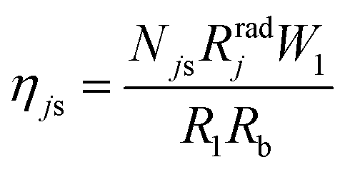
Comparing the behaviours of UCNPs and upconverting microparticles, the results suggest that ρ1 is strongly increased as the size of the particles is reduced. For example, Kaiser et al. compared experimental iQY results of β-NaYF4: 17% Yb3+, 3% Er3+ upconverting microparticles and UCNPs. The iQY of the microparticles shows a saturation point at around 30 W cm−2, and quenching at power densities above it. However, the iQY of UCNPs tends to saturation at the maximum power densities measured, around 4000 W cm−2, which is far above the saturation power density range shown by the microparticles.27 In addition, upconverting microparticles exhibit higher iQYs than those of UCNPs excited at the same power densities,33 and the iQY saturation levels are also higher for microparticles.27 These observations are also supported by numerical simulations, including experimental data, presented by Hossan et al., where the authors compare luminescence and iQY of upconverting microparticles and UCNPs (core and core–shell).44 This occurs because of the relation between the iQY saturation to the largest transition power density point, i.e. ρ1 for the anomalous power density dependence. Within the linear regime and below it, the iQY equation, eqn (9), can be further simplified. Applying the limit ρ1 ≫ ρ, the power density in the denominator that has ρ1 is reduced to ρ1, ρ + ρ1 → ρ1, and eqn (10) is obtained,
| | 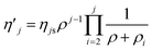 | (10) |
where

[−] is the simplified iQY,
ηjs [−] is the iQY saturation, given by
eqn (11) and obtained from the ratio of the constants outside the product in
eqn (9) to the transition point
ρ1.
| |  | (11) |
Because the iQY saturation is inversely proportional to ρ1, an upconverting material that has lower ρ1 is expected to have higher iQY saturation, which is exactly what is seen in UC microparticles compared to UCNPs.26,27
3.3 The ETU2 case for UCNPs
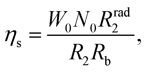
Liu et al.'s model for the ETU2 process22 is a special case of the present general model with W2 = 0, which neglects ETU3 and higher processes. Placing this constant in eqn (8), ρ2 tends to infinity, however, expanding eqn (9) before considering W2 = 0, this constant is cancelled out with the same constant in the denominator of the population density saturation constant N2s. Thereby, the Liu et al.'s solution for the ETU2 process is obtained, eqn (12),| |  | (12) |
where ηs [−] gives the iQY saturation, eqn (13), and ρb [W cm−2] is the balancing power density point, named by Liu et al., eqn (14).| |  | (13) |
| |  | (14) |
From the practical perspective of fitting a QY data curve, eqn (10) for j = 2 and eqn (12) result in the same numerical values for the QY saturation and the transition/balancing power density point. However, the physical nature of the constants can be misleading for the purpose of understanding and engineering optimal UCNPs. The assumption that W2 is null requires ρ1 to be measurable instead of ρ2, in contrast to what is expected for UCNPs, which have an anomalous power density dependence. In any case, the determination of which constant is the highest one is only obtained by measuring the power density dependence of the down converted luminescence to evaluate the population density of the first excited state |1〉. Moreover, several UCNPs have multiple wavelength UC emissions involving ETU2 and higher. For these materials, the ET constants responsible for the population of such higher energy states are required to be larger than zero, and therefore, the general solution is necessary.
3.4 An experimental example
The sample utilised in the experiments presented a hexagonal morphology and 16 ± 2 nm of average size, as shown by the STEM image in Fig. 3. The histogram of size distribution shown in the inset of Fig. 3 was obtained from 100 nanoparticles measured by post analysis of the acquired image. The particles were well dispersed and only insignificant aggregation was observed. The emission spectra of the UCNPs, Fig. 4, show main emission peaks at 474, 650, and 804 nm (ETU3, ETU3 and ETU2 processes, respectively) for the power density range below 100 W cm−2. An ETU4 process (450 nm emission peak) is also present in these UCNPs, although it was only seen for power densities above 1000 W cm−2 (data not shown). The inset of the figure shows the energy level diagram highlighting the electronic transitions of each emission peak.
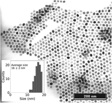 |
| | Fig. 3 The STEM image acquired in the transmission mode shows the UCNPs with an average size of 16 ± 2 nm and hexagonal morphology. The inset displays their size distribution histogram taken from 100 nanoparticles. | |
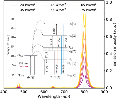 |
| | Fig. 4 Emission spectra of the UCNPs acquired for six different excitation power densities. The UCNPs showed the main emission peak at 804 nm and less intense peaks at 474 nm and 650 nm for the power density range of the measurements. The inset of the figure presents an energy level diagram indicating the electronic transitions corresponding to the emission spectra peaks. | |
The iQY curves for the 804 nm and 474 nm emission versus the excitation power density are shown in Fig. 5. The discrete markers correspond to the experimental data and the continuous curves represent the fitted model, eqn (10). The experimental data and the fitted results displayed in the figure were normalised by their respective iQY saturation values, eqn (11), for a better comparison of the distinct behaviour of the two curves. The iQY saturation values and the transition power density points were obtained by fitting eqn (10) (with j = 2 and j = 3 for the 804 nm and 474 nm emission, respectively) to the experimental iQY data. The results of best fitted parameters are presented in Table 1. The first transition point ρ2 was found to be 20 W cm−2 and the second transition point ρ3 to be 150 W cm−2. The iQY saturation values were found as 0.24% for the 474 nm emission, and 0.78% for the 804 nm emission.
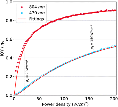 |
| | Fig. 5 Non-beam-profile-compensated-iQY data (discrete markers) for the 804 nm and 474 nm emission fitted with the general model (continuous curves) applied to the ETU2 and ETU3 processes, respectively. The results were normalised by their saturation values for a better comparison of the two curves. The iQY saturation values and the transition power density points are summarised in Table 1. | |
Table 1 Transition power density points and iQY saturation obtained from fitting the general model approximated to the anomalous power density dependence to the iQY versus power density. The experimental data and the fitted curves are shown in Fig. 5
|
λ
em (nm) |
ρ
2 (W cm−2) |
ρ
3 (W cm−2) |
η
s (%) |
| 474 |
20 |
150 |
0.24 |
| 804 |
20 |
— |
0.78 |
Below the first transition point ρ2 the iQY curve for the 804 nm emission has a predominant linear power density dependence, whereas the iQY for the 474 nm emission has a predominant quadratic power density dependence. As the power density is increased above ρ2, the iQY for the 804 nm emission transits to saturation, which was not reached within the power density range of the measurement. For the 474 nm emission, the iQY transits to a linear dependence before the power density approaches the next transition power density point ρ3. Above ρ3, the iQY for the 474 nm emission, finally, transits to saturation. Because, the iQY for an ETU2 process is independent of ρ3, the curve for the 804 nm emission does not undergo any changes at power densities near this transition point. ρ2 and the iQY saturation for the 804 nm emission are in agreement with the balancing power density and iQY points previously reported in the literature for core–shell β-UCNPs with the same dopants and a similar emission spectrum (the iQY at the balancing point is exactly half of the iQY saturation20,22,23). Mousavi et al. reported ρb = 14 W cm−2 and ηs/2 = 0.39% obtained from a beam-profile-compensated QY for the 804 nm emission.23 Liu et al. found ρb = 1.3 W cm−2 and ηs = 2.6% for the 804 nm emission of a non-beam-profile-compensated iQY.22 The latter diverges from the results found here, although the transition power density points and the iQY saturation are strongly dependent on the concentration of the dopants, on the particle size, and on the profile of the excitation beam. Therefore, a more accurate comparison would require the beam profile compensation to be considered. As this is the first work to report the iQY for an ETU3 process in terms of transition points and iQY saturation, ρ3 and the iQY saturation for the 474 nm emission cannot be compared with the existing literature. Comparing the iQY saturation of both emission wavelengths, the results are in agreement with the magnitude of the emission peaks in Fig. 4, and with typical UCNP samples doped with Tm, which present much lower QYs for the 474 nm emission than that for the 804 nm emission.45
4 Conclusion
In conclusion, this paper presented a robust and simple analytical model for an arbitrary ETU process to characterise the iQY of upconverting materials in terms of the transition points of the curves and the iQY saturation level. To exemplify the application of the characterisation method, experimental results of iQY for the 804 nm and 474 nm emissions of a β-NaYF4:YbTm core–shell UCNP were provided. As a result of the analysis of the model, the concepts of “power density transition points” and “iQY saturation” proposed in this work were found in terms of intrinsic properties of the energy levels of the sensitizer and activator ions. In addition, it was found that there is a strong relation between the iQY saturation and the highest power density transition point, which is associated with the first excited state of the activators for UCNPs with anomalous power density dependence. This finding suggests that the properties of the first excited state are related to the fact that upconverting microparticles typically have higher iQYs than UCNPs, and they present a transition power density point, above which, their iQY is reduced to values below the saturation level. The quantification of the transition points is not only important for the determination of the power densities where the behaviours of the UCL and iQY change, but also for the determination of the ET rates. Combining the UCL measurements with life-time measurements, the ET rates are easily obtained for upconverting systems with known activator and sensitizer concentrations. The authors believe that the model proposed in this work provides a powerful tool to accurately characterise upconverting materials and help engineering optimal UCNPs for specific applications, as well as, provide a better understanding of the UC mechanisms.
Author contributions
Conceptualisation, J. S. M., K. K. and S. A. E.; data curation, J. S. M.; formal analysis, J. S. M.; funding acquisition, S. A. E.; investigation, J. S. M. and K. K.; methodology, J. S. M.; project administration, K. K., W. K. K., S. K. V. S. and S. A. E.; software, J. S. M.; supervision, K. K. and S. A. E.; validation, J. S. M., K. K., W. K. K. and S. K. V. S.; visualisation, J. S. M.; writing – original draft, J. S. M.; writing – review & editing, J. S. M., K. K., W. K. K., S. K. V. S. and S. A. E.
Conflicts of interest
The authors declare that they have no conflict of interest.
Acknowledgements
The authors thank the electron microscopy technicians, Michael Schimth and Davinder Singh, for acquiring the STEM images of the UCNPs, and their prompt response. This project is funded by SFI/15/RP/2828.
References
- F. E. Auzel, Proc. IEEE, 1973, 61, 758–786 CAS
 .
.
- F. E. Auzel, C. R. Acad. Sci., 1966, 262, 1016–1019 Search PubMed .
- F. Auzel, Chem. Rev., 2004, 104, 139–173 CrossRef CAS PubMed .
- M. D. Wisser, S. Fischer, C. Siefe, A. P. Alivisatos, A. Salleo and J. A. Dionne, Nano Lett., 2018, 18, 2689–2695 CrossRef CAS PubMed .
- D. Denkova, M. Ploschner, M. Das, L. M. Parker, X. Zheng, Y. Lu, A. Orth, N. H. Packer and J. A. Piper, Nat. Commun., 2019, 10, 1–12 CrossRef CAS PubMed .
- C. Lee, E. Z. Xu, Y. Liu, A. Teitelboim, K. Yao, A. Fernandez-Bravo, A. M. Kotulska, S. H. Nam, Y. D. Suh, A. Bednarkiewicz, B. E. Cohen, E. M. Chan and P. J. Schuck, Nature, 2021, 589, 230–235 CrossRef CAS PubMed .
- C. Chen, L. Ding, B. Liu, Z. Du, Y. Liu, X. Di, X. Shan, C. Lin, M. Zhang, X. Xu, X. Zhong, J. Wang, L. Chang, B. Halkon, X. Chen, F. Cheng and F. Wang, Nano Lett., 2022, 22, 7136–7143 CrossRef CAS PubMed .
- J. De Wild, J. K. Rath, A. Meijerink, W. G. Van Sark and R. E. Schropp, Sol. Energy Mater. Sol. Cells, 2010, 94, 2395–2398 CrossRef CAS .
- T. F. Schulze and T. W. Schmidt, Energy Environ. Sci., 2015, 8, 103–125 RSC .
- N. M. Idris, M. K. Gnanasammandhan, J. Zhang, P. C. Ho, R. Mahendran and Y. Zhang, Nat. Med., 2012, 18, 1580–1585 CrossRef CAS PubMed .
- C. T. Xu, P. Svenmarker, H. Liu, X. Wu, M. E. Messing, L. R. Wallenberg and S. Andersson-Engels, ACS Nano, 2012, 6, 4788–4795 CrossRef CAS PubMed .
- A. Bansal, H. Liu, M. K. G. Jayakumar, S. Andersson-Engels and Y. Zhang, Small, 2016, 12, 1732–1743 CrossRef CAS PubMed .
- T. Xia, Sci. Bull., 2018, 63, 405–407 CrossRef CAS PubMed .
- Y. Wang, L. Bao, Z. Liu and D. W. Pang, Anal. Chem., 2011, 83, 8130–8137 CrossRef CAS PubMed .
- B. Dong, B. Cao, Y. He, Z. Liu, Z. Li and Z. Feng, Adv. Mater., 2012, 24, 1987–1993 CrossRef CAS PubMed .
- E. Martínez, C. Brites, L. Carlos, A. García-Flores, R. Urbano and C. Rettori, Adv. Funct. Mater., 2019, 29, 1807758–1807770 CrossRef .
- T. A. Henderson and L. D. Morries, Neuropsychiatr. Dis. Treat., 2015, 11, 2191–2208 CrossRef CAS PubMed .
- S. Fischer, B. Fröhlich, K. W. Krämer and J. C. Goldschmidt, J. Phys. Chem. C, 2014, 118, 30106–30114 CrossRef CAS .
- S. Fischer, N. J. Johnson, J. Pichaandi, J. C. Goldschmidt and F. C. Van Veggel, J. Appl. Phys., 2015, 118, 193105–193118 CrossRef .
- J. S. Matias, K. Komolibus, S. Konugolu-Venkata-Sekar and S. Andersson-Engels, Nanoscale, 2022, 14, 2230–2237 RSC .
- J. F. Suyver, A. Aebischer, S. García-Revilla, P. Gerner and H. U. Güdel, Phys. Rev. B: Condens. Matter Mater. Phys., 2005, 71, 125123–125132 CrossRef .
- H. Liu, C. T. Xu, D. Lindgren, H. Xie, D. Thomas, C. Gundlach and S. Andersson-Engels, Nanoscale, 2013, 5, 4770–4775 RSC .
- M. Mousavi, B. Thomasson, M. Li, M. Kraft, C. Würth, U. Resch-Genger and S. Andersson-Engels, Phys. Chem. Chem. Phys., 2017, 19, 22016–22022 RSC .
- A. Teitelboim, B. Tian, D. J. Garfield, A. Fernandez-Bravo, A. C. Gotlin, P. J. Schuck, B. E. Cohen and E. M. Chan, J. Phys. Chem. C, 2019, 123, 2678–2689 CrossRef CAS .
- G. Tessitore, G. A. Mandl, M. G. Brik, W. Park and J. A. Capobianco, Nanoscale, 2019, 11, 12015–12029 RSC .
- M. Pokhrel, A. K. Gangadharan and D. K. Sardar, Mater. Lett., 2013, 99, 86–89 CrossRef CAS .
- M. Kaiser, C. Würth, M. Kraft, I. Hyppänen, T. Soukka and U. Resch-Genger, Nanoscale, 2017, 9, 10051–10058 RSC .
- M. Pollnau, D. R. Gamelin, S. R. Lüthi, H. U. Güdel and M. P. Hehlen, Phys. Rev. B: Condens. Matter Mater. Phys., 2000, 61, 3337–3346 CrossRef CAS .
- D. O. Faulkner, S. Petrov, D. D. Perovic, N. P. Kherani and G. A. Ozin, J. Mater. Chem., 2012, 22, 24330–24334 RSC .
- T. Jung, H. L. Jo, S. H. Nam, B. Yoo, Y. Cho, J. Kim, H. M. Kim, T. Hyeon, Y. D. Suh, H. Lee and K. T. Lee, Phys. Chem. Chem. Phys., 2015, 17, 13201–13205 RSC .
- C. Würth, M. Kaiser, S. Wilhelm, B. Grauel, T. Hirsch and U. Resch-Genger, Nanoscale, 2017, 9, 4283–4294 RSC .
- A. Das, C. Mao, S. Cho, K. Kim and W. Park, Nat. Commun., 2018, 9, 4828–4839 CrossRef PubMed .
- C. M. Jones, A. Gakamsky and J. Marques-Hueso, Sci. Technol. Adv. Mater., 2021, 22, 810–848 CrossRef PubMed .
- I. N. Stanton, J. A. Ayres, J. T. Stecher, M. C. Fischer, D. Scharpf, J. D. Scheuch and M. J. Therien, J. Phys. Chem. C, 2018, 122, 252–259 CrossRef CAS .
- S. K. V. Sekar, J. S. Matias, G. Dumlupinar, L. Niemitz, M. Mousavi, K. Komolibus and S. Andersson-Engels, Opt. Express, 2022, 30, 16572–16584 CrossRef PubMed .
- R. Deng, F. Qin, R. Chen, W. Huang, M. Hong and X. Liu, Nat. Nanotechnol., 2015, 10, 237–242 CrossRef CAS PubMed .
- M. Fitzgerald, S. Hodgetts, C. V. D. Heuvel, R. Natoli, N. S. Hart, K. Valter, A. R. Harvey, R. Vink, J. Provis and S. A. Dunlop, Rev. Neurosci., 2013, 24, 205–226 Search PubMed .
- J. R. Jagdeo, L. E. Adams, N. I. Brody and D. M. Siegel, PLoS One, 2012, 7, 1–10 CrossRef PubMed .
- X. Wu, Y. Zhang, K. Takle, O. Bilsel, Z. Li, H. Lee, Z. Zhang, D. Li, W. Fan, C. Duan, E. M. Chan, C. Lois, Y. Xiang and G. Han, ACS Nano, 2016, 10, 1060–1066 CrossRef CAS PubMed .
- Y. Tao, A. J. Y. Huang, Y. Hashimotodani, M. Kano, A. H. All, I. Tsutsui-kimura, K. F. Tanaka, X. Liu and T. J. Mchugh, Science, 2018, 684, 679–684 Search PubMed .
- P. Villanueva-Delgado, K. W. Krämer and R. Valiente, J. Phys. Chem. C, 2015, 119, 23648–23657 CrossRef CAS .
- J. Bergstrand, Q. Liu, B. Huang, X. Peng, C. Würth, U. Resch-Genger, Q. Zhan, J. Widengren, H. Ågren and H. Liu, Nanoscale, 2019, 11, 4959–4969 RSC .
-
J. Matias, Upconversion Virtual Lab, 2023, https://jsmatias-qy-virtuallabapp-home-ch3fhq.streamlit.app/ Search PubMed.
- M. Y. Hossan, A. Hor, Q. Luu, S. J. Smith, P. S. May and M. T. Berry, J. Phys. Chem. C, 2017, 121, 16592–16606 CrossRef CAS .
- M. S. Meijer, P. A. Rojas-Gutierrez, D. Busko, I. A. Howard, F. Frenzel, C. Würth, U. Resch-Genger, B. S. Richards, A. Turshatov, J. A. Capobianco and S. Bonnet, Phys. Chem. Chem. Phys., 2018, 20, 22556–22562 RSC .
|
| This journal is © The Royal Society of Chemistry 2023 |
Click here to see how this site uses Cookies. View our privacy policy here. 
 Open Access Article
 This Open Access Article is licensed under a Creative Commons Attribution-Non Commercial 3.0 Unported Licence
 *ab,
K.
Komolibus
a,
K. W.
Kho
a,
S.
Konugolu-Venkata-Sekar
a and
S.
Andersson-Engels
*ab,
K.
Komolibus
a,
K. W.
Kho
a,
S.
Konugolu-Venkata-Sekar
a and
S.
Andersson-Engels


 [−] is the simplified iQY, ηjs [−] is the iQY saturation, given by eqn (11) and obtained from the ratio of the constants outside the product in eqn (9) to the transition point ρ1.