 Open Access Article
Solution-processed orange and white OLEDs sensitized by an electroactive pure organic room-temperature phosphorescent polymer†
Yiting Tiana,
Renze Heb,
Guoyun Meng *b,
Shumeng Wang
 *c,
Lei Zhaoc and
Junqiao Ding
 *bd
*bd
aSchool of Materials and Energy, Yunnan University, Kunming 650091, P. R. China
bSchool of Chemical Science and Technology, Yunnan University, Kunming 650091, P. R. China. E-mail: mengguoyun@outlook.com; dingjunqiao@ynu.edu.cn
cState Key Laboratory of Polymer Physics and Chemistry, Changchun Institute of Applied Chemistry, Chinese Academy of Sciences, Changchun, 130022, P. R. China. E-mail: wangshumeng@ciac.ac.cn
dSouthwest United Graduate School, Kunming 650092, P. R. China
First published on 7th July 2023
Abstract
Phosphorescence-sensitized fluorescence (PSF) shows great potential for overcoming the 25% internal quantum efficiency limit for fluorescent OLEDs. Other than vacuum thermal deposition, herein we report solution-processed PSF. As a proof of concept, an electroactive pure organic room-temperature phosphorescence (RTP) polymer with sky-blue emission is selected as the sensitizer of the conventional orange fluorescent emitter. Due to the improved exciton utilization, the resultant sensitized device realizes a bright orange electroluminance with a peak external quantum efficiency (EQE) of 6.1% (17.9 cd A−1, 11.0 lm W−1) and Commission Internationale de L’Eclairage (CIE) coordinates of (0.42, 0.47). By optimizing the doping concentration of the fluorescent emitter, furthermore, a spectrally stable white light is also achieved, revealing a maximum EQE of 7.4% (19.3 cd A−1, 12.0 lm W−1) together with CIE coordinates of (0.30, 0.43). The results clearly indicate that solution-processed PSF based on an RTP polymer is a promising approach towards efficient fluorescent OLEDs.
1. Introduction
Organic light-emitting diodes (OLEDs) have been a popular research subject for over three decades, since they hold great potential in flat-panel displays and solid-state lighting.1,2 One of the crucial performance indicators of OLEDs is the internal quantum efficiency (IQE), which is closely related to the spin mixing between singlet and triplet excited states.3,4 As for the conventional fluorescent emitters, however, the IQE is limited to 25% because the generated triplet excitons are almost lost via a non-radiative decay. Therefore, novel classes of emitters have been developed to realize a theoretical 100% IQE nowadays, such as noble metal-containing phosphors and pure organic luminogens capable of thermally activated delayed fluorescence (TADF), room temperature phosphorescence (RTP) or hybridized local and charge-transfer (HLCT) states.5–16As an alternative, TADF-sensitized fluorescence (TSF) and phosphorescence-sensitized fluorescence (PSF) have also been proposed to overcome the above 25% IQE limit.2,17–21 That is, TADF or phosphorescent molecules are adopted as the sensitizer for the conventional fluorescent emitters. In these cases, both singlet and triplet excitons can be harvested through an effective Förster energy transfer from the sensitizer to the fluorescent dopant, leading to a near-unity IQE. For example, Wang and co-workers observed a strong RTP when 2,6-di(phenothiazinyl)naphthalene (β-DPTZN) was doped into a benzimidazole-triazine (PIM-TRZ) host.8 Due to the room temperature phosphorescent nature, the corresponding OLEDs revealed a maximum external quantum efficiency (EQE) of 11.5%. Furthermore, they demonstrated a PSF strategy to construct highly efficient fluorescent OLEDs with RTP using pure organic materials sensitized with fluorescent emitters.11 To this end, a promising EQE of 15.7% was achieved by using PIM-TRZ, β-DPTZN and 5,6,11,12-tetraphenylnaphthacene (rubrene) as the host, phosphor sensitizer and fluorescent emitter, respectively. We note that it is based on vacuum thermal deposition, and there are few reports about solution-processed PSF, which is believed to be more compatible with low-cost, large area and flexible displays in the future.22–25
In addition, solution-processed white OLEDs adopt a straightforward single-emissive-layer structure that incorporates various functional materials, including a host material combined with blue/yellow or blue/green/red emitters. These emitters that encompass all-phosphorescent,26 TADF/phosphorescent hybrid27–30 and all-TADF white OLEDs31–34 have the capability to efficiently harness excitons, thus achieving 100% IQE. However, it is worth noting that there have been limited reports on solution-processed white OLEDs utilizing hybrid pure RTP/fluorescent emitters.
Recently, our group has exploited an electroactive RTP polymer P(DMPAc-O-TPTrz) based on a characteristic donor–oxygen–acceptor geometry.10 Compared with the donor–acceptor reference, the inserted oxygen atom between the donor and acceptor is able to strengthen the spin–orbital coupling effect so as to facilitate the intersystem crossing (ISC) and subsequent phosphorescence, while retaining the intrinsic good electroactivity. Consequently, dominant electrophosphorescence is realized successfully, showing a record-high EQE of 9.7% for solution-processed OLEDs. In this contribution, we further report solution-processed PSF with P(DMPAc-O-TPTrz) as the RTP sensitizer of a fluorescent emitter for orange and white OLEDs.
2. Results and discussion
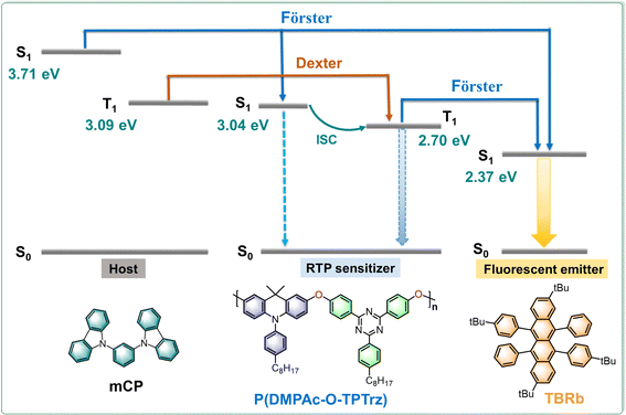
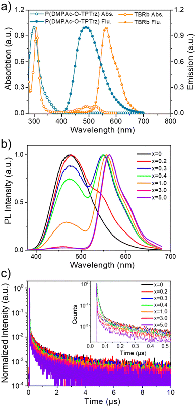
As a proof of concept, the solution-processed PSF consists of P(DMPAc-O-TPTrz) as the RTP sensitizer combined with a wide band gap host and a suitable fluorescent emitter. On one hand, 1,3-di(9H-carbazol-9-yl)benzene (mCP) is employed as the host for P(DMPAc-O-TPTrz), because the triplet energy of mCP is much higher than that of P(DMPAc-O-TPTrz) in order to confine the triplet excitons on P(DMPAc-O-TPTrz) (Fig. 1 and Table S1, ESI†). On the other hand, 2,8-di-tert-butyl-5,11-bis(4-tert-butylphenyl)-6,12-diphenyltetracene (TBRb)35 is delicately selected as the fluorescent dopant because it has a similar energy level alignment (the highest occupied and lowest unoccupied molecular orbitals, HOMO/LUMO) with P(DMPAc-O-TPTrz), so that trap-assisted recombination directly on TBRb can be eliminated to avoid the triplet exciton loss from TBRb (Fig. S2, ESI†). In this case, singlet and triplet excitons may be formed on mCP and/or P(DMPAc-O-TPTrz), followed by energy transfer from mCP to P(DMPAc-O-TPTrz) via Förster and Dexter processes and/or to TBRb through the Förster process. Benefitting from the possible ISC, singlet P(DMPAc-O-TPTrz) can convert into triplet P(DMPAc-O-TPTrz), whose energy is subsequently transformed to singlet TBRb through the Förster process. As a result, both singlet and triplet excitons are utilized for the fluorescence generation of TBRb, thus breaking the IQE limit of 25%.We note that Förster energy transfer plays a critical role in the proposed solution-processed PSF. Therefore, energy transfer between the RTP sensitizer and the fluorescent emitter is first studied before device fabrication. Fig. 2a compares the UV-vis absorption and photoluminescence (PL) spectra of P(DMPAc-O-TPTrz) and TBRb in degassed toluene solutions. It is evident that there is a moderate spectral overlap between the absorption of TBRb and the PL of P(DMPAc-O-TPTrz), ensuring energy transfer from P(DMPAc-O-TPTrz) to TBRb.
To verify this point, the steady-state PL spectra of the doped films were characterized, which are composed of mCP:15 wt% P(DMPAc-O-TPTrz):x wt% TBRb (x = 0, 0.2, 0.3, 0.4, 1.0, 3.0 and 5.0). According to our previous work,10 the content of P(DMPAc-O-TPTrz) is set to be 15 wt%, while the content of TBRb is deliberately changed to investigate the effect of doping concentration on energy transfer. As depicted in Fig. 2b, the codoped film of mCP:15 wt% P(DMPAc-O-TPTrz) exhibits a structureless and broad profile peaking at 476 nm. When the TBRb content is tuned in the range of 0.2–0.4 wt%, a distinct dual emission is observed: one is ascribed to the combination of minor fluorescence and major RTP of P(DMPAc-O-TPTrz) and the other originates from the fluorescence of TBRb. Noticeably, the sky-blue emission from P(DMPAc-O-TPTrz) is found to have completely vanished at the TBRb content of up to 3 wt% and the orange emission from TBRb dominates the whole PL. These observations clearly indicate the improved energy transfer efficiency from P(DMPAc-O-TPTrz) to TBRb with the increasing doping concentration of TBRb.
Also, the transient PL spectra under different doping concentrations were recorded at the emissive maximum of P(DMPAc-O-TPTrz) (476 nm). Consistent with the literature,10 mCP:15 wt% P(DMPAc-O-TPTrz) shows a prompt component from fluorescence with an excited lifetime of 13.57 ns and a delayed component from RTP with an excited lifetime of 1501.43 ns (Fig. 2c and Fig. S3, Table S2, ESI†). After being doped by TBRb, both the fluorescence and RTP seem to be gradually decreased, indicative of energy transfer from P(DMPAc-O-TPTrz) to TBRb. For example, at a 5 wt% doping concentration of TBRb, the detected fluorescence and RTP lifetime are obviously down to 2.91 ns and 892.77 ns, respectively. As discussed above, the RTP nature of P(DMPAc-O-TPTrz) enables the spin-flip from singlet to triplet excitons, whose energy can be subsequently transferred to the singlet TBRb via a Förster process. When the TBRb content grows up, the energy transfer efficiency from P(DMPAc-O-TPTrz) to TBRb is expected to be enhanced, thus leading to reduced fluorescence and RTP lifetimes.
To further elucidate energy transfer, the Förster radius (R0) is determined to be about 2.11 nm according to eqn (1):36,37
 | (1) |
 | (2) |
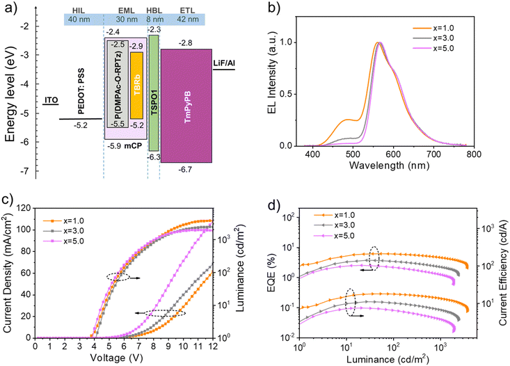
Finally, before device fabrication, we investigated the film morphology using atomic force microscopy (AFM) for both the binary system of mCP:15 wt% P(DMPAc-O-TPTrz) and the ternary system of mCP:15 wt% P(DMPAc-O-TPTrz):x wt% TBRb (x = 0.2 and 1.0). The AFM analysis revealed that these blend films exhibited a homogeneous and flat surface, with root-mean-square (RMS) roughness ranging from 0.376 nm to 0.389 nm (Fig. S4, ESI†). These findings indicate that the blend films possess a favorable film-forming ability, comparable to previous reports,39,40 which is advantageous for device fabrication using solution-processed methods. To evaluate the electroluminescence (EL) performance of the proposed solution-processed PSF, orange OLEDs were fabricated with a device configuration of ITO/PEDOT:PSS (40 nm)/EML (30 nm)/TSPO1 (8 nm)/TmPyPB (42 nm)/LiF (1 nm)/Al (Fig. S5, ESI†). Herein, poly(3,4-ethylenedioxythiophene)/poly(styrenesulfonate) (PEDOT:PSS, Clevios P CH8000), diphenyl[4-(triphenylsilyl)phenyl]phosphine oxide (TSPO1) and 1,3,5-tri[(3-pyridyl)-phen-3-yl]benzene (TmPyPB) act as the hole injection layer, exciton blocking layer and electron transporting layer, respectively. As discussed above, mCP:15 wt% P(DMPAc-O-TPTrz):x wt% TBRb (x = 1.0, 3.0 and 5.0) is used as the emitting layer (EML) owing to the dominant TBRb emission at a high doping concentration.
Fig. 3 plots the energy level alignment of the used materials, the EL spectra at a luminance of around 1000 cd cm−2, current density–voltage–luminance characteristics, and EQE and current efficiency as a function of luminance. As one can see, the charge trap on TBRb is negligible due to the matched energy level alignment between P(DMPAc-O-TPTrz) and TBRb. Therefore, the EL spectra seem to be close to those of the PL counterparts, leading to a bright orange emission with CIE coordinates of (0.42, 0.47), (0.47, 0.48) and (0.49, 0.48) for devices at TBRb contents of 1 wt%, 3 wt% and 5 wt%, respectively (Table 1). Moreover, the current density–voltage curves move towards a lower driving voltage with the increasing TBRb content. Despite this, on going from 1 wt% to 3 wt% and 5 wt%, the maximum EQE is gradually reduced from 6.1% (17.9 cd A−1, 11.0 lm W−1) to 3.7% (11.0 cd A−1, 6.7 lm W−1) and 2.5% (7.5 cd A−1, 5.0 lm W−1) (Fig. S5, ESI†). This trend is understandable when considering the concentration quenching of TBRb and the enhanced unwanted Dexter energy from the triplet P(DMPAc-O-TPTrz) to the triplet TBRb.18,41 The device stability with a TBRb content of 1.0 wt% was also estimated and the corresponding lifetime (LT50, lifetime to 50% of the initial luminance) was found to be 0.66 h at an initial luminance of 100 cd m−2 (Fig. S6, ESI†). Further experiments about device structure optimization are needed to enhance their longevity and stability, such as modifying the PEDOT:PSS layer, inserting an additional hole transporting layer, using a more stable electron transporting layer instead of TmPyPB, encapsulating the fresh devices and so on.
| TBRb content (x wt%) | V on [V] | L max [cd m−2] | PEd [lm W−1] | CEd [cd A−1] | EQEd [%] | CIEe (x, y) |
|---|---|---|---|---|---|---|
| a With mCP:15 wt% P(DMPAc-O-TPTrz):x wt% TBRb as the EML. b With mCP:5 wt% TBRb as the EML. c Turn-on voltage at 1 cd m−2. d Maximum data. e At 1000 cd cm−2. Lmax: maximum luminance; PE: power efficiency; CE: current efficiency; and EQE: external quantum efficiency. | ||||||
| x = 1.0a | 3.8 | 3765 | 11.0 | 17.9 | 6.1 | (0.42, 0.47) |
| x = 3.0a | 4.2 | 2476 | 6.7 | 11.0 | 3.7 | (0.47, 0.48) |
| x = 5.0a | 4.0 | 1961 | 5.0 | 7.5 | 2.5 | (0.49, 0.48) |
| x = 5.0b | 5.0 | 655 | 2.3 | 4.5 | 1.5 | (0.50, 0.48) |
At the same time, a control device was also prepared based on mCP:5 wt% TBRb as the EML. Obviously, an orange EL is observed with a maximum EQE of 1.5% (4.5 cd A−1, 2.3 lm W−1) and CIE coordinates of (0.50, 0.48) (Fig. S8, ESI†). Compared with mCP:15 wt% P(DMPAc-O-TPTrz): 5 wt% TBRb, the EQE is decreased by about 40% in the absence of the RTP sensitizer P(DMPAc-O-TPTrz). This clearly highlights the critical role of P(DMPAc-O-TPTrz), which can be adopted as the RTP sensitizer for efficient exciton utilization in conventional fluorescent OLEDs.
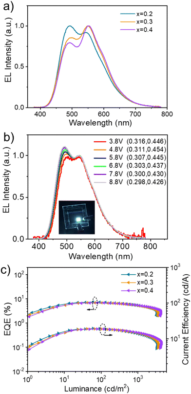
Besides orange, solution-processed white EL is also achieved by regulating the doping concentration of TBRb. That is, both emissions from P(DMPAc-O-TPTrz) peaking at 497 nm and TBRb peaking at 550 nm appear simultaneously as the TBRb content is lowered to 0.2–0.4 wt% (Fig. 4a). Consequently, the corresponding EL spectra cover the whole visible region from 400 nm to 750 nm, resulting in white light. At a brightness of 1000 cd m−2, the white light devices exhibit CIE coordinates of (0.30, 0.43), (0.32, 0.45) and (0.34, 0.45) for TBRb concentrations of 0.2 wt%, 0.3 wt% and 0.4 wt%, together with the color rendering index (CRI) and correlated color temperature (CCT) of 66/6491 K, 66/5812 K and 67/5458 K, respectively (Table 2). In addition, the white light devices show good spectral stability (Fig. S9, ESI†), while the slight variation in the relative intensity of the two emission peaks (497 and 550 nm) upon increasing the driving voltages can be attributed to the exciton saturation of the TBRb dopant.42,43 Taking 0.2 wt% TBRb as an example, the CIE coordinates slightly change from (0.316, 0.446) to (0.298, 0.426) when the voltage is increased from 3.8 V to 8.8 V (Fig. 4b). Meanwhile, it reveals a maximum EQE of 7.4%, a maximum current efficiency of 19.3 cd A−1 and a maximum power efficiency of 12.0 lm W−1 (Fig. 4c and Fig. S10, ESI†). Even at a high luminance of 1000 cd m−2, the EQE still remains at 5.3%, indicative of a small efficiency roll-off.
| TBRb content (x wt%) | V on [V] | L max [cd m−2] | PEc [lm W−1] | CEc [cd A−1] | EQEc [%] | CIEd (x, y) | CCTd [K] | CRId |
|---|---|---|---|---|---|---|---|---|
| a With mCP:15 wt% P(DMPAc-O-TPTrz):x wt% TBRb as the EML. b Turn-on voltage at 1 cd m−2. c Data at maximum, 100 and 1000 cd m−2. d At 1000 cd cm−2. CCT: correlated color temperature; CRI: color rendering index. | ||||||||
| x = 0.2 a | 3.8 | 3374 | 12.0/11.0/5.9 | 19.3/18.9/14.0 | 7.4/7.2/5.3 | (0.30, 0.43) | 6491 | 66 |
| x = 0.3 a | 4.0 | 3587 | 11.8/10.9/5.9 | 18.8/18.6/14.0 | 6.9/6.8/5.1 | (0.32, 0.45) | 5812 | 66 |
| x = 0.4 a | 4.0 | 4293 | 11.7/10.8/6.3 | 18.7/18.6/14.6 | 6.8/6.8/5.3 | (0.34, 0.45) | 5458 | 67 |
3. Conclusions
To summarize, we have demonstrated solution-processed orange and white OLEDs sensitized by an electroactive pure organic RTP polymer. The strategy is based on the combination of P(DMPAc-O-TPTrz) as the RTP sensitizer and TBRb as the fluorescent emitter. Benefitting from efficient exciton utilization, a bright orange EL is obtained at a high doping concentration of TBRb. The corresponding EQE and CIE coordinates are 6.1% and (0.42, 0.47), respectively. Further lowering the TBRb content leads to a stable warm white light with a promising EQE of 7.4% (19.3 cd A−1, 12.0 lm W−1) and CIE coordinates of (0.30, 0.43). We believe that this work will shed light on the development of solution-processed PSF for efficient fluorescent OLEDs.Author contributions
J. D. conceived and supervised the project. Y. T., R. H., S. W., and L. Z. performed the experiments and analyzed the data. J. D., S. W. and G. M. drafted the manuscript and revised the manuscript. All authors commented on the manuscript.Conflicts of interest
There are no conflicts to declare.Acknowledgements
The authors acknowledge financial support from the National Natural Science Foundation of China (No. 52273198 and 51873205) and the Scientific Research Foundation for Introduced Talents of Yunnan University (CZ21623201). We also thank Advanced Analysis and Measurement Center of Yunnan University for the assistance with instrumentation.Notes and references
- C. W. Tang and S. A. VanSlyke, Appl. Phys. Lett., 1987, 51, 913–915 CrossRef CAS.
- M. A. Baldo, D. F. O'Brien, Y. You, A. Shoustikov, S. Sibley, M. E. Thompson and S. R. Forrest, Nature, 1998, 395, 151–154 CrossRef CAS.
- H. Uoyama, K. Goushi, K. Shizu, H. Nomura and C. Adachi, Nature, 2012, 492, 234–238 CrossRef CAS PubMed.
- Z. Yang, Z. Mao, Z. Xie, Y. Zhang, S. Liu, J. Zhao, J. Xu, Z. Chi and M. P. Aldred, Chem. Soc. Rev., 2017, 46, 915–1016 RSC.
- R. Hamze, J. L. Peltier, D. Sylvinson, M. Jung, J. Cardenas, R. Haiges, M. Soleilhavoup, R. Jazzar, P. I. Djurovich, G. Bertrand and M. E. Thompson, Science, 2019, 363, 601–606 CrossRef CAS PubMed.
- J. Lee, H. F. Chen, T. Batagoda, C. Coburn, P. I. Djurovich, M. E. Thompson and S. R. Forrest, Nat. Mater., 2016, 15, 92–98 CrossRef CAS PubMed.
- L.-S. Cui, A. J. Gillett, S.-F. Zhang, H. Ye, Y. Liu, X.-K. Chen, Z.-S. Lin, E. W. Evans, W. K. Myers, T. K. Ronson, H. Nakanotani, S. Reineke, J.-L. Bredas, C. Adachi and R. H. Friend, Nat. Photonics, 2020, 14, 636–642 CrossRef CAS.
- J. Wang, B. Liang, J. Wei, Z. Li, Y. Xu, T. Yang, C. Li and Y. Wang, Angew. Chem., Int. Ed., 2021, 60, 15335–15339 CrossRef CAS PubMed.
- L. Xu, Y. Mo, N. Su, C. Shi, N. Sun, Y. Zhang, L. Duan, Z. H. Lu and J. Ding, Nat. Commun., 2023, 14, 1678 CrossRef CAS PubMed.
- X. Liu, L. Yang, X. Li, L. Zhao, S. Wang, Z. H. Lu, J. Ding and L. Wang, Angew. Chem., Int. Ed., 2021, 60, 2455–2463 CrossRef CAS PubMed.
- J. Wang, J. Liang, Y. Xu, B. Liang, J. Wei, C. Li, X. Mu, K. Ye and Y. Wang, J. Phys. Chem. Lett., 2019, 10, 5983–5988 CrossRef CAS PubMed.
- H. F. Higginbotham, M. Okazaki, P. de Silva, S. Minakata, Y. Takeda and P. Data, ACS Appl. Mater. Interfaces, 2021, 13, 2899–2907 CrossRef CAS PubMed.
- Z. Chen, M. Li, Q. Gu, X. Peng, W. Qiu, W. Xie, D. Liu, Y. Jiao, K. Liu, J. Zhou and S. J. Su, Adv. Sci., 2023, 10, e2207003 CrossRef PubMed.
- W. Z. Yuan, X. Y. Shen, H. Zhao, J. W. Y. Lam, L. Tang, P. Lu, C. Wang, Y. Liu, Z. Wang, Q. Zheng, J. Z. Sun, Y. Ma and B. Z. Tang, J. Phys. Chem. C, 2010, 114, 6090–6099 CrossRef CAS.
- Y. Xu, P. Xu, D. Hu and Y. Ma, Chem. Soc. Rev., 2021, 50, 1030–1069 RSC.
- W. Li, Y. Pan, R. Xiao, Q. Peng, S. Zhang, D. Ma, F. Li, F. Shen, Y. Wang, B. Yang and Y. Ma, Adv. Funct. Mater., 2014, 24, 1609–1614 CrossRef CAS.
- D. Zhang, L. Duan, C. Li, Y. Li, H. Li, D. Zhang and Y. Qiu, Adv. Mater., 2014, 26, 5050–5055 CrossRef CAS PubMed.
- H. Nakanotani, T. Higuchi, T. Furukawa, K. Masui, K. Morimoto, M. Numata, H. Tanaka, Y. Sagara, T. Yasuda and C. Adachi, Nat. Commun., 2014, 5, 4016–4023 CrossRef CAS PubMed.
- X. Wu, X. Peng, L. Chen, B. Z. Tang and Z. Zhao, ACS Mater. Lett., 2023, 5, 664–672 CrossRef CAS.
- J. Yao, Y. Chen, Y. Wu, X. Qiao, D. Yang, Y. Dai, Q. Sun and D. Ma, J. Mater. Chem. C, 2020, 8, 1666–1672 RSC.
- K. H. Lee and J. Y. Lee, J. Mater. Chem. C, 2019, 7, 8562–8568 RSC.
- X. Cai, Y. Xu, Y. Pan, L. Li, Y. Pu, X. Zhuang, C. Li and Y. Wang, Angew. Chem., Int. Ed., 2023, 62, e202216473 CrossRef CAS PubMed.
- Y. Wang, K. Zhang, F. Chen, X. Wang, Q. Yang, S. Wang, S. Shao and L. Wang, Chin. J. Chem., 2022, 40, 2671–2677 CrossRef CAS.
- Z. Zhang, W. Wang, Y. Jiang, Y. X. Wang, Y. Wu, J. C. Lai, S. Niu, C. Xu, C. C. Shih, C. Wang, H. Yan, L. Galuska, N. Prine, H. C. Wu, D. Zhong, G. Chen, N. Matsuhisa, Y. Zheng, Z. Yu, Y. Wang, R. Dauskardt, X. Gu, J. B. Tok and Z. Bao, Nature, 2022, 603, 624–630 CrossRef CAS PubMed.
- W. Liu, C. Zhang, R. Alessandri, B. T. Diroll, Y. Li, H. Liang, X. Fan, K. Wang, H. Cho, Y. Liu, Y. Dai, Q. Su, N. Li, S. Li, S. Wai, Q. Li, S. Shao, L. Wang, J. Xu, X. Zhang, D. V. Talapin, J. J. de Pablo and S. Wang, Nat. Mater., 2023, 22, 737–745 CrossRef CAS PubMed.
- C.-L. Ho, W.-Y. Wong, Q. Wang, D. Ma, L. Wang and Z. Lin, Adv. Funct. Mater., 2008, 18, 928–937 CrossRef CAS.
- L. Chen, Y. Chang, S. Shi, S. Wang and L. Wang, Mater. Horiz., 2022, 9, 1299–1308 RSC.
- J. Zhao, S. Yuan, X. Du, W. Li, C. Zheng, S. Tao and X. Zhang, Adv. Opt. Mater., 2018, 6, 1800825 CrossRef.
- D. Zhang, L. Duan, Y. Zhang, M. Cai, D. Zhang and Y. Qiu, Light: Sci. Appl., 2015, 4, e232 CrossRef CAS.
- J. Y. Wu and S. A. Chen, ACS Appl. Mater. Interfaces, 2018, 10, 4851–4859 CrossRef CAS PubMed.
- A. M. Polgar, C. M. Tonge, C. J. Christopherson, N. R. Paisley, A. C. Reyes and Z. M. Hudson, ACS Appl. Mater. Interfaces, 2020, 12, 38602–38613 CrossRef CAS PubMed.
- X. Chen, Z. Yang, W. Li, Z. Mao, J. Zhao, Y. Zhang, Y. C. Wu, S. Jiao, Y. Liu and Z. Chi, ACS Appl. Mater. Interfaces, 2019, 11, 39026–39034 CrossRef CAS PubMed.
- C. Xue, H. Lin, G. Zhang, Y. Hu, W. Jiang, J. Lang, D. Wang and G. Xing, J. Mater. Sci.: Mater. Electron., 2020, 31, 4444–4462 CrossRef CAS.
- J. Hu, Q. Li, X. Wang, S. Shao, L. Wang, X. Jing and F. Wang, Angew. Chem., Int. Ed., 2019, 58, 8405–8409 CrossRef CAS PubMed.
- Y.-S. Wu, T.-H. Liu, H.-H. Chen and C. H. Chen, Thin Solid Films, 2006, 496, 626–630 CrossRef CAS.
- J. Yao, W. Liu, C. Lin, Q. Sun, Y. Dai, X. Qiao, D. Yang, J. Chen and D. Ma, J. Mater. Chem. C, 2021, 9, 3626–3634 RSC.
- W. Xie, X. Peng, M. Li, W. Qiu, W. Li, Q. Gu, Y. Jiao, Z. Chen, Y. Gan, K. K. Liu and S. J. Su, Adv. Opt. Mater., 2022, 10, 2200665 CrossRef CAS.
- P. E. Shaw, A. Ruseckas, J. Peet, G. C. Bazan and I. D. W. Samuel, Adv. Funct. Mater., 2010, 20, 155–161 CrossRef CAS.
- X. Li, K. Bai, S. Wang, J. Ding and L. Wang, J. Mater. Chem. C, 2019, 7, 2633–2639 RSC.
- L. Yang, X. Li, Q. Yang, S. Wang, H. Tian, J. Ding and L. Wang, Chem. Eng. J., 2022, 436, 135221 CrossRef CAS.
- C. Duan, Y. Xin, Z. Wang, J. Zhang, C. Han and H. Xu, Chem. Sci., 2021, 13, 159–169 RSC.
- D. Zhang, M. Cai, Y. Zhang, D. Zhang and L. Duan, ACS Appl. Mater. Interfaces, 2015, 7, 28693–28700 CrossRef CAS PubMed.
- C. J. Zheng, J. Wang, J. Ye, M. F. Lo, X. K. Liu, M. K. Fung, X. H. Zhang and C. S. Lee, Adv. Mater., 2013, 25, 2205–2211 CrossRef CAS PubMed.
Footnote |
| † Electronic supplementary information (ESI) available. See DOI: https://doi.org/10.1039/d3ma00326d |
| This journal is © The Royal Society of Chemistry 2023 |


