 Open Access Article
Insoluble oxalates modified K2XF6:Mn4+ (X = Ti, Ge, Si) red-emitting phosphors exhibiting excellent moisture resistance and luminescence for warm white light-emitting diodes†
Lidan
Han
,
Rui
Zhang
 *,
Yanhui
Chen
,
Chen
Jiang
and
Xiaoli
Wu

Key Laboratory of Nonferrous Materials and New Processing Technology, Ministry of Education, Guangxi Key Laboratory of Optical and Electronic Materials and Devices, College of Materials Science and Engineering, Guilin University of Technology, Guilin, 541004, P. R. China. E-mail: rzhang@glut.edu.cn
First published on 9th January 2023
Abstract
K2XF6:Mn4+ (X = Ti, Ge, Si) phosphors are attractive red-light sources in the warm white light-emitting diodes. However, these fluorides suffer from hydrolysis in moist environments, making them less acceptable in the lighting market. Insoluble MC2O4 (M = Ca, Sr, Ba, Mn) was modified on the fluorides’ surfaces to prevent the hydrolysis of internal [MnF6]2− groups and promote the reduction of exposed Mn4+ ions into Mn2+ ones. The reaction mechanism was studied, as well as the effect of modification on the crystal structures and particle morphologies. The luminescence properties of CaC2O4 modified fluorides were studied in detail. The luminescence weakens with increasing coatings because of light scattering at the interfaces. However, the luminescence intensity exceeded its initial value after being immersed in water even for 200 h. Besides, the modified fluorides possessed excellent thermal stability than the original ones. The LED devices made using commercial Y3Al5O12:Ce3+ and CaC2O4 modified K2TiF6:Mn4+ exhibited warm white light emission with luminous efficiency of 120.5 lm W−1, correlated color temperature of 4179 K, and color rendering index (Ra) of 83.0 when operated at 40 mA. It indicates a novel method to improve the Mn4+-doped fluoride phosphors toward commercial application.
1. Introduction
Red-emitting phosphors are indispensable components in white light-emitting diodes (LEDs) for high quality lighting. Most recently, Mn4+-doped fluoride phosphors, such as A2MF6: Mn4+ (A = Li, Na, K, Rb, Cs; M = Si, Ge, Ti, Zr, Sn, Hf), A3TF6:Mn4+ (T = Al, Ga, Sc), and A2ZF7:Mn4+ (Z = Nb, Ta), have gained increasing attention because of the intense broadband excitation centered at ∼460 nm and sharp line emission located at ∼630 nm.1–6 Besides, these low-cost and readily available phosphors possess considerable quantum yield and excellent thermal stability, which are very favorable to warm white LEDs.7,8 However, the exposed [MnF6]2− groups of fluoride phosphors are likely to be hydrolyzed to manganese dioxide (MnO2) and hydrofluoric acid (HF) in humid environments.9–11 Such easy hydrolysis and inherently unstable features seriously deteriorate the luminescence performances of fluorides and make them less acceptable in the lighting market. Inhibiting the hydrolysis of [MnF6]2− is thus urgent for improving Mn4+-doped fluoride phosphors.In general, the surfaces of moisture sensitive materials are modified by isolation layers to protect them from water erosion.12 Compact coatings are helpful in reducing the exposure of active ions or groups. Meanwhile, they are optically transparent in the visible region, aiming at minimizing luminescence losses.13 One kind of isolation layer is a homogeneous shell, which eliminates the lattice defects and increases the emission efficiency of fluoride phosphors. For example, Zhu et al. reported a reverse cation exchange method to construct a core–shell structured K2TiF6:Mn4+@K2TiF6 phosphor, where the shell prevented moisture in the air from hydrolyzing the internal [MnF6]2− groups and effectively cut off the path of energy migration to surface defects.14 Zhang et al. developed a surface passivation strategy to make an Mn4+-rare surface protective layer covering the K2XF6:Mn4+ (X = Ti, Si, Ge) phosphors, whose luminescence intensity still remained at 97% after being soaked in distilled water for 12 h.15 The other kinds of isolation layers are heterogeneous organic hydrophobic coatings (oleic acid, alkyl phosphate, silane coupling agents, etc.) or insoluble inorganic layers (Al2O3, carbon, SrF2, etc.). For example, Arunkumar et al. generated an oleic acid coating on the K2SiF6:Mn4+ surface through the formation of hydrogen bonds between fluoride ions and hydrogen.16 Verstraete et al. coated Al2O3 or TiO2 thin shells on the K2SiF6:Mn4+ surface by atomic layer deposition.17 In our previous work, K2TiF6: Mn4+ was modified with SrF2 coatings with the aid of KHF2 transition layer to moderate the lattice mismatch.18 These protective layers significantly improve the moisture resistance of fluoride phosphors. Despite all this, it is worth developing a novel waterproof strategy for Mn4+-doped fluoride phosphors.
Herein, we present a facile and mild approach to construct insoluble oxalates (MC2O4, M = Ca, Sr, Ba, Mn) modified K2XF6:Mn4+ (X = Ti, Ge, Si) red-emitting phosphors. The structures, morphologies, and luminescence properties of as-modified phosphors have been investigated in detail, in addition to the moisture resistance after being immersed in distilled water for various time durations. Most Mn4+ ions are protected from water erosion by oxalate coating. Besides, tiny amounts of exposed Mn4+ ions on the fluoride surfaces were reduced to Mn2+ ions in situ, forming a K2XF6 protective shell. It indicates that the insoluble oxalate modification strategy provides a novel reference for Mn4+-doped fluoride phosphors.
2. Experimental section
2.1 Materials and synthesis
The raw materials KF·2H2O, KMnO4, (NH4)2SiF6, (NH4)2TiF6, GeO2, M(NO3)2 (M = Ca, Sr, Ba, Mn), oxalic acid (H2C2O4), H2O2 (30 wt%), HF (49 wt%), and anhydrous ethanol were purchased from Sinopharm chemical reagent Co., Ltd. All the chemicals were of analytical grade and used directly without further purification.K2MnF6 was synthesized according to Bode's method.19 Typically, 5 g KF·2H2O and 0.4 g KMnO4 were fully dissolved in 10 ml HF, then 0.4 ml H2O2 was slowly dropped into the purplish-black solution under vigorous stirring. When the solution color changed to yellowish, the precipitates were filtrated, washed twice with anhydrous alcohol, and finally dried at 80 °C for 2 h to obtain K2MnF6.
K2XF6:Mn4+ (X = Ti, Si, Ge) was synthesized through a cation exchange and co-precipitation combined synthesis. In a typical procedure, 0.002 mol K2MnF6 and 0.04 mol (NH4)2TiF6 (or (NH4)2SiF6, GeO2) were thoroughly dissolved in 40 ml HF, while 0.16 mol KF·2H2O was dissolved in 20 ml distilled water. Then, the KF solution was slowly dropped into the former acidic solution under vigorous stirring. After being stirred for 20 min, the yellowish precipitations were filtered and washed twice with anhydrous alcohol and finally dried at 80 °C for 2 h to obtain K2XF6:Mn4+ (X = Ti, Si, Ge).
Insoluble oxalates MC2O4 (M = Ca, Sr, Ba, Mn) modified K2XF6:Mn4+ (X = Ti, Ge, Si) was prepared through a chemical precipitation reaction. In a typical procedure, 0.02 mol K2XF6: Mn4+ was completely dispersed in 40 ml anhydrous ethanol under vigorous stirring, and then 0.5–5 ml 1.0 mol L−1 M(NO3)2 (M = Ca, Sr, Ba, Mn) aqueous solution and equal amounts of 1.0 mol L−1 H2C2O4 aqueous solution were dropped into the turbid liquid in turn. After 20 min of stirring, the precipitations were filtered and washed twice with anhydrous alcohol and finally dried at 80 °C for 2 h to obtain K2XF6:Mn4+@xMC2O4 (x = 0.05, 0.10, 0.20, 0.30, 0.50).
The K2XF6:Mn4+@0.1CaC2O4 red-emitting phosphor and commercial YAG:Ce3+ yellow phosphor (Luming technology group Co., Ltd) were evenly mixed with silicone gel (the mass ratio of phosphors to silicone gel was 1![[thin space (1/6-em)]](https://www.rsc.org/images/entities/char_2009.gif) :
:![[thin space (1/6-em)]](https://www.rsc.org/images/entities/char_2009.gif) 20). The obtained mixture was coated on the blue InGaN chips (460–465 nm, Hongqi Optoelectronics Co., Ltd) to fabricate white LEDs.
20). The obtained mixture was coated on the blue InGaN chips (460–465 nm, Hongqi Optoelectronics Co., Ltd) to fabricate white LEDs.
2.2 Characterization
The X-ray diffraction (XRD) patterns were characterized on an X-ray spectrophotometer (X’ Pert PRO) using the Cu Ka1 irradiation source at λ = 1.5406 Å, a tube voltage of 40 kV, and a tube current of 40 mA. The appearances and elemental compositions were respectively investigated on a scanning electron microscope (SEM, Gemini SEM 300) with an accompanying energy dispersive spectrometer (EDS) and a transmission electron microscope (TEM, JEM-2100F). The surface element compositions and chemical changes were analyzed using X-ray photoelectron spectroscopy (XPS, ESCALAB 250Xi) and inductively coupled plasma optical emission spectrometer (ICP-OES, Optima 8000). The photo-luminescence (PL) excitation and emission spectra were measured using a steady-state and transient fluorescence spectrophotometer (QuantaMaster 8000, HORIBA). The temperature dependent PL spectra excited at 465 nm were recorded when the samples were put on a cooling/heating stage (THMS 600, Linkam Scientific Instruments) in the range of 77 to 873 K. The photoelectric properties of as-fabricated white LED devices were measured in an integrating sphere of 50 cm diameter connected to a CCD detector with an optical fiber (HAAS-2000, Everfine).3. Results and discussion
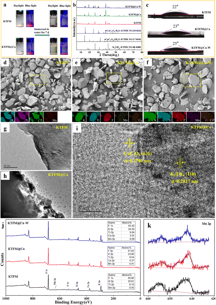
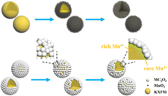
The surface modification process is exhibited in Scheme 1. The formation of oxalate protective layers on the K2XF6:Mn4+ (X = Ti, Ge, Si) surfaces proceeds by a usual chemical precipitation reaction of heterogeneous nucleation. After dropping H2C2O4, the fluorides easily attract the hydrogen ions to form hydrogen bonds. Thus, the H2C2O4 is enriched on the surfaces of K2XF6, which leads to the nucleation and crystal growth of MC2O4 (M = Ca, Sr, Ba, Mn). Besides, it is the fluorine hydrogen bond that moderates the interfacial lattice mismatch.To verify the waterproof effect, comparisons are first made between K2TiF6:Mn4+ (KTFM) and CaC2O4 modified KTFM (KTFM@Ca). As shown in Fig. 1a, both samples exhibit the same appearance in the daylight and bright red luminescence under 460 nm blue light irradiation. After being immersed in distilled water for 7 days, the KTFM changes its color from yellowish to black, showing no luminescence when irradiated by blue light. However, nearly no change is found for both the appearance and luminescence of KTFM@Ca. A similar situation is observed in the CaC2O4 modified K2SiF6:Mn4+ and K2GeF6:Mn4+ (Fig. S1, ESI†). It indicates that the coatings play a vital role in improving water resistance. The changes in crystal structures, particle morphologies, and Mn ion valence states are studied to clarify the reasons. Fig. 1b exhibits the XRD patterns of KTFM, KTFM@Ca, and soaked KTFM@Ca (denoted as KTFM@Ca-W). The diffraction peaks of KTFM are observed to be well indexed to hexagonal K2TiF6 (JCPDS No. 08-0488). No other impurity phase is detected, indicating the substitution of Mn4+ ions for Ti4+ ones owing to similar radii (Mn4+, r = 0.54 Å; Ti4+, r = 0.61 Å).20 As for KTFM@Ca, the diffraction peaks of CaC2O4·2H2O (JCPDS No. 17-0541) appear besides those of K2TiF6. Besides, the diffraction peaks of CaC2O4·2H2O disappear in KTFM@Ca-W, while those of CaC2O4·H2O (JCPDS No. 20-0231) show up. Similarly, the XRD patterns hardly change in the CaC2O4 modified K2SiF6: Mn4+ and K2GeF6:Mn4+ after being soaked (Fig. S2, ESI†). It suggests that the CaC2O4 coatings hardly change in distilled water. The contact angles of phosphors and water were also tested after the samples being pressed into tablets. As shown in Fig. 1c, the contact angles are 22°, 23°, and 25° for KTTM, KTFM@Ca, and KTFM@Ca-W, respectively. It confirms that the samples are surface hydrophilic, and the water resistance enhancement is originated from the insoluble shell. SEM images shown in Fig. 1d–f indicate that the KTFM particles are nearly hexagonal plate shaped, and the KTFM@Ca and KTFM@Ca-W particles almost keep the same appearance. TEM images shown in Fig. 1g–i verify that the CaC2O4 nanoparticles are well modified on the surfaces of KTFM, and the integration between them is close. EDS mapping images exhibit that Ti and Mn element signals are uniformly distributed on every sample, but the Ca element signal only enriches on the surfaces of KTFM@Ca and KTFM@Ca-W. Referring to the XRD results and TEM images, the surface layer is CaC2O4. Similarly, no obvious change is observed in the morphologies and element distributions of CaC2O4 modified K2SiF6:Mn4+ and K2GeF6: Mn4+ (Fig. S3, ESI†). Fig. 1j and k exhibit the XPS spectra of samples, where the K, Ti, F, and Mn elements are observed from every sample, while the Ca element is only detected from the modified ones as expected. Noticeably, the signal position of the Mn element hardly changes, while the atomic percentage declines sharply after being soaked. Besides, the ICP results shown in Table S1 (ESI†) confirm that the content of the Mn element decreases from 2.82% to 2.04% for KTFM@Ca and KTFM@Ca-W. It indicates that the exposed Mn4+ ions react in distilled water. In fact, some bubbles were observed on the vessel wall when the KTFM samples were soaked, and the product of evaporation solution was confirmed to be K2TiF6 and K2TiOF4 (Fig. S4, ESI†). Therefore, the involved chemical reactions are summarized as follows:
| [TiF6]2− + H2O → [TiOF4]2− + 2H+ + 2F− | (1) |
| [MnF6]2− + 2H2O → MnO2 + 4H+ + 6F− | (2) |
| MC2O4 ↔ M2+ + C2O42− | (3) |
| C2O42− + MnO2 + 4H+ → 2CO2 + 2H2O + Mn2+ | (4) |
The evolution process of Mn4+-doped fluoride phosphors in water is shown in Scheme 2. The [MnF6]2− groups are easily hydrolyzed to MnO2 after being soaked, making the surfaces of fluorides loose and porous. Thus, the internal [MnF6]2− groups are gradually exposed and then hydrolyzed until completely exhausted. After oxalate modification, a trace of hydrolyzed C2O42− ions can soon reduce the MnO2 into Mn2+ ions. The MnO2-induced loose surfaces turn to a compact fluoride shell with few Mn4+ ions, which significantly retards the hydrolysis of [MnF6]2− groups and enhances the water resistance.
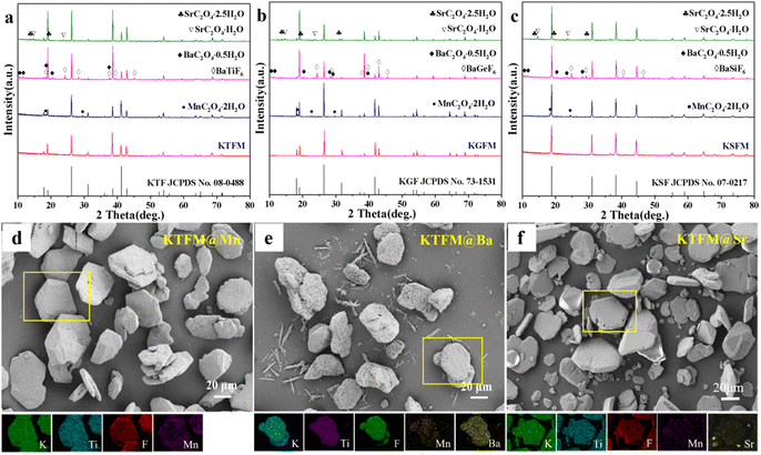
Besides CaC2O4 coated fluorides, MC2O4 (M = Mn, Sr, Ba) modified K2XF6:Mn4+ (X = Ti, Ge, Si) were prepared in the same way. Fig. 2a–c exhibit the XRD patterns, in which the intense diffraction peaks are well consistent with the standard cards of K2XF6 (X = Ti, Ge, Si; JCPDS No. 08-0488, 73-1531, 07-0217). Besides, there are some weak diffraction peaks, which respectively indexed to the MnC2O4·2H2O (JCPDS No. 25-0544), BaXF6 (X = Ti, Ge, Si; JCPDS No. 01-0508, 74-0924, 15-0736) and BaC2O4·0.5H2O (JCPDS No. 20-0134), and SrC2O4·xH2O (x = 1, 2.5; JCPDS No. 20-1203, 20-1204). Fig. 2d–f show the SEM and EDS mapping images of MC2O4 (M = Mn, Sr, Ba) modified K2TiF6:Mn4+. All the samples possess nearly hexagonal plate shaped morphology as KTFM, while the surfaces are coated with small particles. Besides, Mn, Ba, and Sr element signals are observed to be uniformly distributed on the particles, indicating a perfect oxalate shell. It can be seen that the oxalate modification hardly destroys the morphologies and crystal structures of fluoride phosphors, but promotes a thin protective shell on the surfaces.
 | ||
| Fig. 2 (a)–(c) XRD patterns of MC2O4 (M = Sr, Ba, Mn) modified K2XF6:Mn4+ (X = Ti, Ge, Si). (d)–(f) SEM and EDS mapping images of MC2O4 (M = Sr, Ba, Mn) modified K2TiF6:Mn4+. | ||
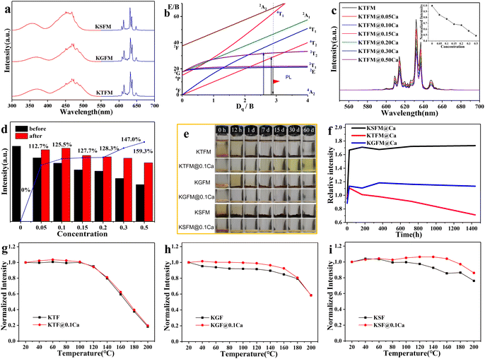
Luminescence properties of CaC2O4 modified K2XF6:Mn4+ (X = Ti, Ge, Si) were studied to make clear the influence of oxalate coatings. Fig. 3a shows the PL excitation and emission spectra of the original fluorides. All samples exhibit two broad excitation bands around 360 and 460 nm, which originated from the spin-allowed 4A2g → 4T1g and 4A2g → 4T2g electron transitions of Mn4+ (3d3). Besides, several emission lines ranging from 580 to 660 nm are observed due to the spin constraint 2Eg → 4A2 transitions. The emission peak positions are similar to each other, which is ascribed to an almost constant Mn4+:2Eg energy level in the octahedral sites of fluorides (Fig. 3b). After CaC2O4 modification, the PL behavior hardly changes, while the PL intensity declines gradually with increasing coatings (Fig. 3c). It is the crystal lattice mismatch that makes the light scattering stronger at the interfaces. Furthermore, the modified samples (0.15 g) were immersed in water (3 ml) for 7 days to find out the effect of CaC2O4 content. Fig. 3d exhibits the normalized PL intensities and retention ratios of soaked samples. The soaked KTFM absolutely quenches its luminescence owing to the hydrolysis of [MnF6]2− groups, while each soaked KTFM@Ca exhibits enhancing PL intensity because of a compact KTF shell with few Mn4+ ions formed on the surface. Notably, the PL intensity of soaked KTFM@0.1Ca exhibits 1.25 times the initial value, which is close to that of the original KTFM. Furthermore, the original and CaC2O4 modified K2XF6:Mn4+ (X = Ti, Ge, Si) were immersed in water at various times. The actual photographs in Fig. 3e show that the original K2XF6: Mn4+ changed the colors from yellowish to black after being soaked for 12 h, while the CaC2O4 modified samples retained the initial colors even for 30 days. Fig. 3f exhibits the normalized PL intensities of CaC2O4 modified samples soaked for various times. After a transitory increase, the PL intensity of KTFM@ 0.1Ca weakens slowly owing to the dissolution of the shell, while those of KGFM@0.1Ca and KSFM@0.1Ca keep on a steady value due to the formation of silica/germanium gel. The temperature dependent PL spectra of original and CaC2O4 modified K2XF6:Mn4+ (X = Ti, Ge, Si) were also investigated. As shown in Fig. 3g–i, the PL intensities of samples are invariable below 100 °C and then weaken monotonously with increasing temperature. It is found that the thermal stability of KTFM remains unchanged after modification, while those of KGFM and KSFM exhibit obvious enhancements. The thermal stability improvement may be ascribed to three possible aspects: (i) The surface thermal resistances and specific surface areas increase after modification.18 (ii) The oxalate coatings absorb heat to lose the crystal water or decompose, and then the actual temperature of inner phosphors is lower than the apparent one, which improves the thermal quenching of luminescence. (iii) The decomposition of oxalate coatings leads to thinner shells and thus less light scattering at the interfaces. It indicates that the modified phosphors are suitable for white LED lighting.
To evaluate the potential application in white LEDs, the lighting devices were made by encapsulating commercial YAG: Ce3+ with different ratios of KTFM@0.1Ca on the 460 nm blue InGaN chips. Fig. 4a exhibits the normalized luminous spectra and actual photographs of devices operated at 3.2 V and 320 mA. Red emission lines enhance gradually with the increase of KTFM@0.1Ca. Correspondingly, the chromaticity coordinates of devices shift towards the warm white light area along the blackbody radiation curve, as shown in Fig. 4b. Table S2 (ESI†) shows the key opto-electronic parameters of devices. LED-0 (only YAG:Ce3+) shows a luminous efficiency (LE) of 100.4 lm W−1, correlated color temperature (CCT) of 5410 K, and color rendering index (Ra) of 72.0. After the addition of KTFM@0.1Ca, the LE value shows a slight decline, while the Ra and CCT improve evidently. Noticeably, LED-2 exhibits good LE of 79.0 lm W−1 (CCT = 4275 K, Ra = 81.7). Moreover, the LE of LED-2 increases to 120.5 lm W−1 (CCT = 4179 K, Ra = 83.0) when operated at 40 mA (Table S3, ESI†). Furthermore, Fig. 4c shows the normalized luminous spectra of LED-2 operated at various drive currents (40–320 mA). The curves essentially remain the same, indicating that the color fluctuation is very small. These results demonstrate that the modified red phosphor is a promising candidate for warm white LEDs.
4. Conclusions
In summary, insoluble MC2O4 (M = Ca, Sr, Ba, Mn) was successfully modified on the surfaces of K2XF6:Mn4+ (X = Ti, Ge, Si). The coatings substantially improve the fluorides’ water resistance by preventing the unhopeful hydrolysis of internal [MnF6]2− groups and reducing the exposed Mn4+ ions to Mn2+ ones. The appearances, particle sizes, and crystallographic structures of fluorides are almost maintained after modification. The luminescence of modified fluorides weakens with increasing coatings because of light scattering at the interfaces. However, the luminescence even enhances after being soaked for 200 h. Thermal stability is also promoted owing to the increase of surface thermal resistance and specific surface areas. The white LED device fabricated using commercial Y3Al5O12:Ce3+ and as-prepared K2TiF6:Mn4+@0.1Ca exhibits excellent optoelectronic parameters (LE = 120.5 lm W−1, CCT = 4179 K, Ra = 83.0) and small color fluctuation. It suggests that the insoluble oxalate modification strategy provides a novel idea for improving the Mn4+-doped fluoride phosphors for warm white LEDs.Conflicts of interest
There are no conflicts to declare.Acknowledgements
This work was financially supported by the National Natural Science Foundation of China (No. 52062008), the Natural Science Foundation of Guangxi province (No. 2018GXNSFAA050021), the opening fund of Key Laboratory of New Processing Technology for Nonferrous Metal & Materials, Ministry of Education/Guangxi Key Laboratory of Optical and Electronic Materials and Devices (No. 20AA-20), and the Guangxi Distinguished Experts Special Fund (2019B06).Notes and references
- L. Lv, Z. Chen, G. Liu, S. Huang and Y. Pan, J. Mater. Chem. C, 2015, 3, 1935–1941 RSC.
- C. C. Lin, A. Meijerink and R. S. Liu, J. Phys. Chem. Lett., 2016, 7, 495–503 CrossRef CAS PubMed.
- M. H. Fang, H. D. Nguyen, C. C. Lin and R. S. Liu, J. Mater. Chem. C, 2015, 3, 7277–7280 RSC.
- E. Song, J. Wang, J. Shi, T. Deng, S. Ye, M. Peng, J. Wang, L. Wondraczek and Q. Y. Zhang, ACS Appl. Mater. Interfaces, 2017, 9, 8805–8812 CrossRef CAS PubMed.
- T. T. Deng, E. H. Song, J. Sun, L. Y. Wang, Y. Deng, S. Ye, J. Wang and Q. Y. Zhang, J. Mater. Chem. C, 2017, 5, 2910–2918 RSC.
- H. Lin, T. Hu, Q. Huang, Y. Cheng, B. Wang, J. Xu, J. Wang and Y. Wang, Laser Photonics Rev., 2017, 11, 1700148 CrossRef.
- C. Jiang, L. Li, M. G. Brik, L. Lin and M. Peng, J. Mater. Chem. C, 2019, 7, 6077–6084 RSC.
- L. L. Wei, C. C. Lin, M. H. Fang, M. G. Brik, S. F. Hu, H. Jiao and R. S. Liu, J. Mater. Chem. C, 2015, 3, 1655–1660 RSC.
- Y. X. Liu, J. X. Hu, L. C. Ju, C. Cai, V. B. Hao, S. H. Zhang, Z. W. Zhang, X. Xu, X. Jian and L. J. Yin, Ceram. Int., 2020, 46, 8811–8818 CrossRef CAS.
- Y. Li, Y. Yu, X. Zhong, Y. Liu, L. Chen, S. Liao, Y. Huang and H. Zhang, J. Lumin., 2021, 234, 117968 CrossRef CAS.
- Y. Liu, Z. Zhou, L. Huang, M. G. Brik, S. Si, L. Lin, T. Xuan, H. Liang, J. Qiu and J. Wang, J. Mater. Chem. C, 2019, 7, 2401–2407 RSC.
- Y. Y. Zhou, E. H. Song, T. T. Deng and Q. Y. Zhang, ACS Appl. Mater. Interfaces, 2018, 10, 880–889 CrossRef CAS PubMed.
- H. D. Nguyen, C. C. Lin and R. S. Liu, Angew. Chem., Int. Ed., 2015, 54, 10862–10866 CrossRef CAS PubMed.
- D. Huang, H. Zhu, Z. Deng, Q. Zou, H. Lu, X. Yi, W. Guo, C. Lu and X. Chen, Angew. Chem., Int. Ed., 2019, 58, 3843–3847 CrossRef CAS PubMed.
- Y. Zhou, E. Song, T. Deng, Y. Wang, Z. Xia and Q. Y. Zhang, Adv. Mater. Interfaces, 2019, 6, 1802006 CrossRef.
- P. Arunkumar, Y. H. Kim, H. J. Kim, S. Unithrattil and W. B. Im, ACS Appl. Mater. Interfaces, 2017, 9, 7232–7240 CrossRef CAS PubMed.
- R. Verstraete, G. Rampelberg, H. Rijckaert, I. Van Driessche, E. Coetsee, M. M. Duvenhage, P. F. Smet, C. Detavernier, H. Swart and D. Poelman, Chem. Mater., 2019, 31, 7192–7202 CrossRef CAS.
- Z. Fang, X. Lai, J. Zhang and R. Zhang, Int. J. Appl. Ceram. Technol., 2021, 18, 1106–1113 CrossRef CAS.
- H. Bode, H. Jenssen and F. Bandte, Angew. Chem., Int. Ed. Engl., 1953, 65, 304 CrossRef CAS.
- R. D. Shannon, Acta Crystallogr., Sect. A: Cryst. Phys., Diffr., Theor. Gen. Crystallogr., 1976, 32, 751–767 CrossRef.
Footnote |
| † Electronic supplementary information (ESI) available: Actual photographs, XRD patterns, SEM images and EDS mapping images of products; Key optoelectronic parameters of devices. See DOI: https://doi.org/10.1039/d2ma01023b |
| This journal is © The Royal Society of Chemistry 2023 |


