
 Open Access Article
 This Open Access Article is licensed under a
 Creative Commons Attribution 3.0 Unported Licence
Multi Jet Fusion printed lattice materials: characterization and prediction of mechanical performance
Andrew Yen-Jong
Chen
 a,
Ailin
Chen
a,
Andrew
Fitzhugh
b,
Aja
Hartman
b,
Pierre
Kaiser
b,
Ihuoma
Nwaogwugwu
b,
Jun
Zeng
b and
Grace X.
Gu
*a
a,
Ailin
Chen
a,
Andrew
Fitzhugh
b,
Aja
Hartman
b,
Pierre
Kaiser
b,
Ihuoma
Nwaogwugwu
b,
Jun
Zeng
b and
Grace X.
Gu
*a
aDepartment of Mechanical Engineering, University of California, Berkeley, CA 94720, USA. E-mail: ggu@berkeley.edu
bHP Inc, Palo Alto, CA 94304, USA
First published on 16th January 2023
Abstract
Multi Jet Fusion (MJF) is a powder-bed fusion (PBF) additive manufacturing process that enables high-resolution, rapid fabrication of large-scale polymer parts. In particular, the MJF process enables direct printing of structures without the need for support material, enabling complex geometries such as lattices and scaffolds to be manufactured with minimal post-processing. The lattice structure is a highly tunable geometry that can form the stiff, strong backbone of larger-scale designs, facilitating time and material efficiency in the printing process compared to a solid body. While the benefits of lattice-based designs produced with powder-bed fusion processes are clear, there currently exist few studies that empirically characterize the mechanical performance of lattices printed using MJF. In this work, we treat each lattice as an assembly of components (beams and nodes), with each component defined by its nominal size and orientation. To study the effect of changing these parameters on material properties, lattice unit cells of structural interest are modeled with their beam diameters, node sizes, and unit cell geometries varied. Specimens are printed using polyamide (PA)-12 powder, then mechanically tested to determine strength and stiffness. The results are used to determine empirical fitting parameters to the Gibson–Ashby scaling model of lattices, previously unapplied to MJF-printed structures. To further develop a model of the structure's geometry-dependent behavior, the varying failure modes of printed lattices are also characterized. The results of this work provide a foundation for the design optimization of lattices printed using Multi Jet Fusion, in turn developing a fundamental model for a variety of large-scale printable structures.
Introduction
Additive manufacturing (AM) has enabled the fabrication of complex geometries and components in the past decade.1–6 Multi Jet Fusion (MJF) is a powder-bed fusion (PBF) AM process used for large-scale manufacturing of polymers.7 The MJF process proceeds layer-by-layer to form solid geometries from powder feedstock, controlling the fused geometry using droplets of liquid selectively ejected from inkjet heads. During the printing process, a thin layer of powder is first spread evenly across the printing bed. Then, inkjets dispense liquid “fusing” and “detailing” agents, which determine the amount of energy locally absorbed when the powder-bed is subsequently exposed to infrared light. In regions where fusing agent is applied, energy absorption is high, and the powder melts and subsequently recrystallizes, creating a “fused” part. Conversely, powder remains unfused in the print volume where detailing agent is deposited. The cycle of powder spreading, inkjet deposition, and infrared light exposure repeats until all desired regions in the build volume are consolidated.8 After printing, the powder bed is allowed to cool until the handling temperature is reached, at which point fused parts are removed from the bed of powder and may be bead-blasted to remove residual unfused powder from their surfaces. For the experimental work described in this paper, finished parts require no additional post-processing to achieve stable mechanical or chemical properties. The unfused powder from a build volume can be mixed with fresh powder and reused in future print jobs.9 The most common feedstock materials used with the MJF process include thermoplastic polymers like polyamide (PA)-12, a versatile engineering material. PA-12 is an important structural material with favorable stiffness and strength characteristics for applications in the automotive, biomedical, and aerospace industries, among others.For the printing of PA-12 and other thermoplastics, powder-bed fusion techniques like MJF are particularly advantageous compared to other 3D-printing methods because parts of any geometry can be printed in any orientation within the print bed without the need for support material. In turn, complex geometries that are significantly challenging or physically impossible to build using other AM methods can be realized using PBF.10–12 The printing volume of leading MJF printers also allows for large parts or even multi-part assemblies with moving components to be manufactured directly without fasteners or other off-the-shelf parts. Additionally, the MJF printing process does not require chemical post-processing (e.g., solvent baths) to achieve desired mechanical properties or to remove unwanted material. Taken together, these advantages suggest the high potential for MJF-printed parts to have optimized mechanical performance.
Particularly, the design phase can be highly tailored to take advantage of the strengths of the MJF process. The printing of large-scale structural elements (e.g., beams) of arbitrary size in arbitrary positions and orientations suggests that the overall mechanical properties of structures printed using MJF can be highly programmable. One common strategy to enable programmable mechanical properties is to replace parts or all of a solid body with a lattice structure, which can be easily accomplished using generatively-driven topology optimization routines.13 Broadly speaking, a lattice structure consists of a single unit cell, which consists of individual beam elements arranged to be joined at vertices, translated regularly in space (i.e., tessellated) without gaps.14 Different lattice structures of the same material transfer loads in different ways; the geometric parameters of a lattice unit cell, including the size and aspect ratio of beams and the nodal connectivity of vertices, determine its mechanical properties and response to applied stress.15–18
In particular, there is a scaling relationship between the strength and stiffness of a lattice structure and its density, which is related to the aspect ratio of a given beam in the lattice.19 The specific scaling factors of strength and stiffness for a given lattice geometry depend on the connectivity of unit cell vertices. Moreover, beyond quantifying the efficiency of scaling of mechanical properties, this nodal connectivity parameter can be used to predict how the lattice structure will behave under an applied compressive load, both as a large-scale structure and on the level of individual beam elements.20–22 Therefore, when designing parts that consist of lattice elements, it is critical to understand not only how the overarching geometry drives mechanical behavior, but also how the theoretical scaling parameters might be adjusted for the intricacies of a particular material-manufacturing system.
Because the Multi Jet Fusion process can be used to readily manufacture architectures having programmable material properties with high fidelity and reproducibility, and at increased throughputs compared to other additive manufacturing processes, the printing of lattice structures using MJF technology has garnered significant attention in recent years.23,24 However, few studies in the current literature thoroughly empirically characterize the mechanical performance of PA-12 lattices printed using MJF with regard to geometric characteristics, especially nodal connectivity. Specifically, the scaling relationships for relative density, stiffness, and strength, important parameters for optimization-based design, are absent in the current literature.
This work aims to experimentally characterize the mechanical properties of MJF-printed PA-12 lattice structures of several commonly used geometries. The relative density, compressive stiffness, and compressive strength of specimens are studied and related to the fundamental parameter of beam aspect ratio, which can be viewed as an aggregate metric that combines several design variables like the size and density of unit cells. To measure these properties, we select three lattice structures of different nodal connectivities and vary individual beam thicknesses, unit cell densities, and specimen sizes over a range that captures the design space of commonly printed MJF structures. After printing, we test the structures to failure in compression and extract stiffness and strength data. The empirical correlations developed as a result of this testing can be used to directly predict the mechanical properties of, and by extension inform the design of, structures printed in PA-12 using MJF. At a broader scale, when compared to similar datasets resulting from other printing methods and material systems (see the Discussion section), the data from this study continues to refine the first-principles models that can be used to describe lattice behavior.
Classical beam theory
The classical theory of lattice behavior under uniaxial compressive loading is based on the work of Gibson and Ashby.25 Considering a unit cell as a collection of cylindrical beams of finite length, diameter, and mass, joined at vertices (nodes) of zero volume, the classical beam theory uses first-principles of solid mechanics to describe the action of the lattice structure in compression and subsequently the scaling of its mechanical properties with geometric attributes. Depending on its nodal connectivity, which is defined as the average number of beams joined at a given vertex, a particular unit cell can be classified as either bending-dominated or stretch-dominated. Bending-dominated structures have relatively low nodal connectivity, and hence the fixity of each node results in large internal moments that develop within each beam member. In contrast, stretch-dominated structures have high nodal connectivity – being fully triangulated in the limit – and experience primarily axial stresses in each beam. However, experimental data using other material systems has demonstrated that the dichotomy between bending and stretching is not entirely absolute; rather, some structures with “intermediate” nodal connectivity demonstrate behaviors that can be described as a composite of the two paradigms. Nevertheless, the overarching framework of bending-dominated and stretch-dominated lattices continues to form the basis of the scaling-law argument.Gibson and Ashby demonstrated that for all lattices, both bending- and stretch-dominated, a power-law relationship exists between a lattice structure's density ρ and its stiffness E and strength σ:
| Erel = Cρmrel, σrel = Dρnrel |
Here, the subscript rel indicates that a value is normalized to the bulk property corresponding to a solid of the same material. According to classical beam theory, the exponents m and n are solely dependent on the lattice geometry, where bending-dominated structures and stretch-dominated structures have different values of the constants. The scaling exponent for strength, n, further depends on the particular failure mode (e.g., fracture or buckling) of the structure, as the critical failure stress is a function of the failure mode itself. The coefficients C and D are constants of proportionality that do not scale with beam behavior; they effectively normalize the values relative to the bulk material properties.
Considering the beams as ideal cylinders having radius r and length L and the nodes as zero-volume point elements, purely geometric relationships can be used to derive the theoretical scaling between the beam aspect ratio (r/L) and the relative density of the unit cell. Generally speaking, a higher aspect ratio correlates with a higher density. Specifically, to a first-order approximation, it is appropriate to write a relationship of the form
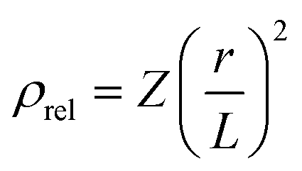
| Geometry | Average nodal connectivity | Density scaling coefficient Z | Theoretical exponents | |
|---|---|---|---|---|
| Stiffness m | Strength n | |||
| Tetrakaidecahedron (Kelvin) | 4 |
|
2 | 1.5 |
| Simple cubic | 6 | 3π | 1 | 1 (stretching), 2 (buckling) |
| Octet-truss | 12 |
|
1 | 1 |
The Gibson–Ashby scaling relationships can be applied to a wide variety of material and manufacturing systems and is an excellent first-principles modeling approach for most conventional lattice structures. However, two important limitations merit further discussion. First, the classical theory assumes that all beams are joined at dimensionless, weightless nodes. In reality, however, the nodes occupy finite volumes and are themselves capable of responding to applied stresses. The presence of finite nodes also changes (i.e., decreases) the effective length of beam elements compared to theoretical predictions. Considering the effect of node size leads to slight modifications of the scaling relationships, most notably to include additional terms that consider the contributions of the node volumes to stiffness and strength.26
Additionally, the scaling laws of stiffness and strength can vary in different relative density regimes. For slender structures, i.e., those with low values of r/L – and hence low densities – the traditional bending and stretching arguments apply most exactly. For structures of higher aspect ratio and relative density, however, experimental data shows that the nodal connectivity is no longer the primary predictor of scaling constants. Rather, recent studies have demonstrated a combination of bending and stretching behavior in these non-slender structures, leading to higher stiffnesses than predicted.27
In the present work, the effect of node volume is primarily neglected, because the as-printed node size is fixed for all specimens by the resolution of the printer. However, the effect of relative density cannot be ignored in these empirical correlations. Therefore, the data is split into two groups using a threshold relative density of 10%. Specifically, we refer to “slender” structures having ρrel < 10%, and “non-slender” structures having ρrel ≥ 10%. In general, numerical analysis (e.g., fitting constants) will be done for each group separately; thus, the effect of slenderness on stiffness and strength can be accurately captured.
Materials and methods
Experimental design
Three principal lattice structures are chosen for study, representing three regimes of nodal connectivity: tetrakaidecahedron, simple cubic, and octet-truss. The tetrakaidecahedron cell (also called the Kelvin cell) is a structure having fourteen faces, eight hexagonal and six quadrilateral.28 Each unit cell has an average nodal connectivity of 4, corresponding to bending-dominated behavior predicted by classical beam theory. The simple cubic cell, with a structure consisting of uniform cubes, has an average nodal connectivity of 6, which falls between the bending-dominated and stretch-dominated regimes. In uniaxial compression, the simple cubic structure is of particular interest because it most directly admits the failure mode of beam buckling for sufficiently high applied stresses. Finally, the octet-truss cell is a fully triangulated structure whose nodal connectivity is 12.29 Hence, the octet cell approximates a structure governed by purely axial forces and hence, according to classical beam theory, should exhibit stretch-dominated behavior.To study density, stiffness, and strength at a comprehensive range of beam aspect ratios, three primary attributes – the size of the entire specimen, the beam thickness, and the number of unit cells in a specimen (i.e., the unit cell density) – are varied amongst specimens of a single structure (Fig. 1). The range of variables studied is chosen to emulate real structures printed using the MJF process for a variety of applications. Specifically, in sizing individual features and overall specimen dimensions, we consider processing characteristics such as printed dimensional accuracy, removal of unfused powder from printed surfaces, and protection against part fracture during bead-blasting. Table 2 describes the minimum, maximum, and step size for each of the variables.
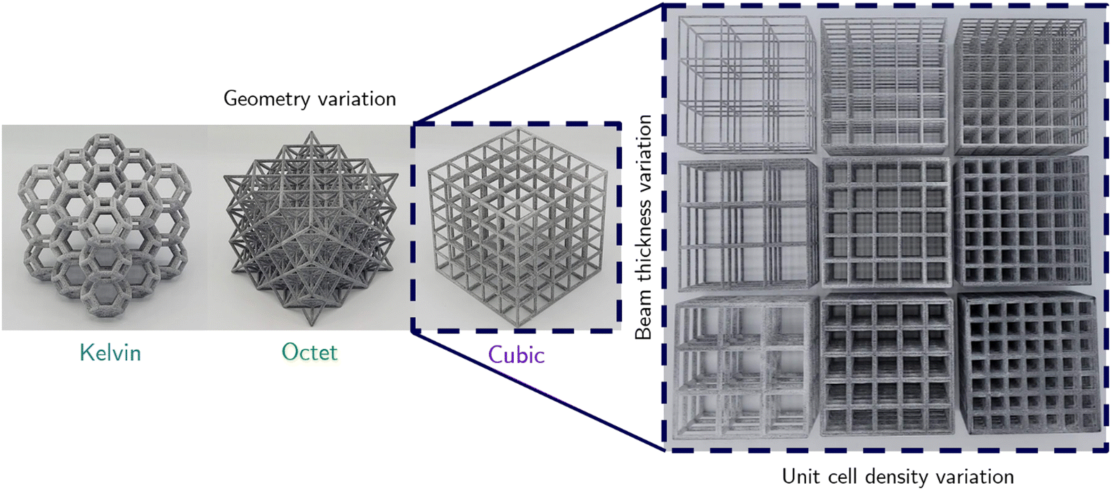 | ||
| Fig. 1 Overview of the experimental parameters. To study the mechanical behavior of specimens over a wide range of relative densities, the beam thickness and unit cell density are varied for each of the three unit cell geometries. | ||
| Variable | Min | Max | Step |
|---|---|---|---|
| Geometry | Kelvin/Octet/Cubic | ||
| Unit cell count | 3 | 7 | 2 |
| Beam thickness, mm | 1 | 3 | 1 |
| Specimen size, mm | 45 | 90 | 15 |
Building and printing
A total of thirty-six specimens are thus prepared for each unit cell geometry. The lattice specimens are generated iteratively using the nTopology modeling software and packed at random within the printer's build volume to minimize the effect of print location on material properties. All structures are oriented parallel to the bounding-box of the build volume for symmetry and to exclude the effect of print angle on material properties. The parts are printed on an HP Jet Fusion 5200 3D-printer with HP 3D High Reusability PA-12 material using the “Balanced” print mode, which enforces a layer height of 80 microns. After printing and the manufacturer-recommended subsequent “natural” cooling cycle within the build unit, the fused parts are extracted from the powder bed and cleaned of excess powder in an automated bead-blaster (Powershot C automatic sand blaster, DyeMansion). After cleaning, the weight and overall dimensions of each specimen (length, width, and height in the direction parallel to compression) are recorded, in addition to the average thickness of five randomly selected beams.Mechanical testing
The specimens are then tested in uniaxial compression using an Instron 5900-series universal testing system. Specimens are compressed at a rate of 5 mm min−1 until ultimate failure, or for samples exhibiting densification behavior, until 90% strain is attained. The compressive modulus is calculated using a least-squares regression on the initial, linear portion of the compressive stress–strain curve, and the ultimate compressive strength is recorded as the maximum stress attained by the sample before failure. Samples that exhibit densification behavior are excluded from strength calculations, but the initial, pre-plateau region is used to extract a stiffness measurement.Experimental results
Density scaling
By plotting the relative density of each specimen against beam aspect ratio, the empirical relative density scaling coefficient, Z, for each unit cell geometry is obtained using a least-squares regression (Fig. 2). Table 3 compares the theoretical predictions and experimental results.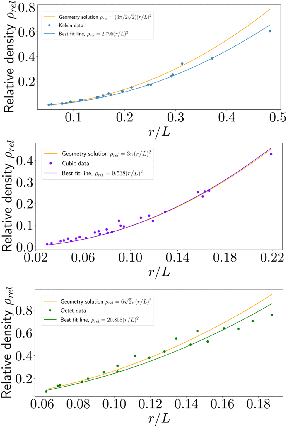 | ||
| Fig. 2 Empirical relative density relationships as a function of beam aspect ratio, r/L, for each geometry. The first-order model is also shown for reference, although slight disagreement exists due to double-counting of the nodal intersections, particularly at high relative densities. | ||
| Geometry | Theoretical | Experimental | Pct. difference (%) |
|---|---|---|---|
| Tetrakaidecahedron (Kelvin) |
|
2.795 | −16.120 |
| Simple cubic | 3π≈ 9.424 | 9.538 | 1.201 |
| Octet-truss |
|
20.858 | −21.755 |
The printed simple cubic structures demonstrate good adherence to the theoretical prediction. However, for both the Kelvin and Octet samples, the first-order model using geometrical considerations overpredicts the relative density of printed parts. An explanation for this phenomenon can be traced back to the derivation of the first-order scaling relationship.27 The source of the deviation is twofold. First, when computing the relative density of a given lattice, the model uses an average unit cell assumed to be located in the bulk of the material. The printed models, however, contain a number of “edge” unit cells that have more material than their counterparts in the bulk. This effect leads to underprediction of relative density, particularly for specimens containing a low number of total unit cells. Second, the first-order model, which models beams as ideal cylinders, neglects to account for the intersection of beams at each node. The intersecting area that is “double-counted” is a function of the aspect ratio of the beam and the angle of intersection, which varies between lattice geometries. This double-counting effect is negligible at low relative densities, but leads to an overestimation at higher relative densities. The interplay between these two phenomena at different aspect ratios, specimen sizes, and beam intersection angles accounts for the net apparent discrepancy in the density scaling results, especially for the Kelvin and Octet cells, which have a large number of beams meeting at non-right angles. In reality, more refined models that are not log-linear, such as that of Chen and Tan,30 produce better agreement with the experimental data in this study. The remaining correlations in the present study which concern relative density, such as that of stiffness and strength scaling, use the measured experimental data.
Stress–strain behavior and failure methods
Under the applied compressive load, structures exhibit geometry-dependent behavior. Two main classes of behavior are observed: either ultimate failure caused by fracture of individual beams, or a “plateau” region of nearly perfectly-plastic behavior followed by a subsequent “densification” region. In the former case, an ultimate compressive strength is attained; however, specimens that exhibited densification appear to show a dramatic increase in load-carrying capacity with increasing strain. However, the sharp rise in stress during densification is a geometric effect, primarily due to the physical contact of unbroken beams as the entire structure is crushed at high strains. Hence, the densification behavior itself is of little practical value when considering the initial geometry of each specimen, and this regime does not represent a tunable material property. However, the high strain-to-failure characteristic of lattices that do not fracture may be further explored to take advantage of toughness and energy-absorption properties, which combined with the large volume format of MJF printing demonstrates a high degree of potential when properly architected. Specifically, the combination of design parameters that generate lattices with this behavior (e.g., low aspect ratio, low connectivity) appear differently for different lattice geometries, indicating that toughness may be a tunable property.Kelvin structures, having low connectivity, exhibit both types of behavior distinctly (Fig. 3a). Specimens with low beam aspect ratios display a plateau region followed by densification, with a high degree of beam bending evident in compressed specimens as early as a few percent strain. Specimens with higher aspect ratios reach a critical stress for fracture instead of plateauing, and the primary failure mode is the fracture of individual beam elements usually localized to a single horizontal plane of unit cells. Thus, many specimens that fail by fracture have several intact rows of unit cells above and below the failure plane; it is hypothesized that failure is associated with the plane containing the highest density of void defects in the fused powder.
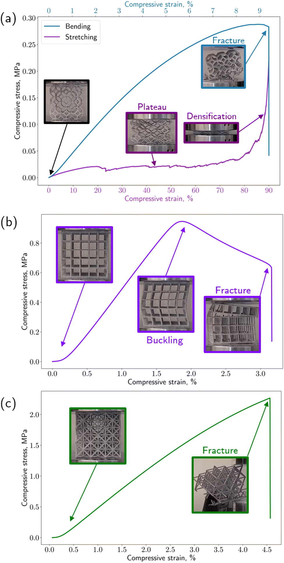 | ||
| Fig. 3 Typical compressive force–displacement behavior until fracture or densification for the three lattice geometries studied, in order of increasing nodal connectivity: (a) Kelvin, (b) cubic, and (c) octet. In panel a, two distinct behaviors of Kelvin cells are plotted: bending-dominated behavior with fracture (blue, upper curve), which is associated with higher strut thicknesses, and stretching-dominated behavior with densification (purple, lower curve), evident in specimens with lower strut thicknesses. | ||
Cubic structures, loaded in uniaxial compression parallel to their beam elements, display an initial linear stress–strain relationship, up until the critical stress at which beam buckling occurs (Fig. 3b). This critical stress corresponds to the ultimate compressive strength of the cubic lattice structure. After this threshold, the vertically oriented beams clearly buckle and the stress–strain characteristic displays a nearly linear region of decreasing stress as buckling worsens, before ultimate failure by fracture. Similar to the Kelvin structures, fracture is often localized to one horizontal plane of beam members. Compared to the Kelvin structures that fail by fracture, the cubic structures attain a higher toughness due to the additional strain associated with the buckling regime before ultimate failure.
Octet structures (Fig. 3c), which have the highest nodal connectivity of the geometries tested, uniformly fail by fracture of the beams, with very little plastic deformation evident in the stress–strain characteristic. The onset of failure, however, is not catastrophic; rather, individual beam elements are observed to fracture in succession until a stable load-transfer path vanishes, at which point the remaining structure fails catastrophically. The successive failure of single beams is likely attributed to the presence of void defects randomly scattered throughout the specimen. Due to the triangulation of the geometry, which creates a high number of possible load-transfer paths, the structure can remain globally stable while sporadic, local fracture events of individual beams occur without largely impacting the load-carrying capacity of the specimen.
Stiffness and strength scaling
Table 4 presents the experimental scaling exponents of stiffness and strength as a function of relative density, computed separately for the slender and non-slender regimes. To determine the value of the experimental constants, a linear regression is performed on a log–log transformation of the empirical data, where the slope of the best-fit line represents the scaling exponent. For comparison, the theoretical exponent predicted by classical beam theory is also listed. The theoretical strength exponent n = 2 for the simple cubic structure is selected on the basis of the observed primary failure behavior, buckling.| Geometry | Stiffness exponent m | Strength exponent n | ||||
|---|---|---|---|---|---|---|
| ρ rel < 0.1 | Theory | ρ rel ≥ 0.1 | ρ rel < 0.1 | Theory | ρ rel ≥ 0.1 | |
| Kelvin | 2.37 | 2 | 1.78 | 1.73 | 1.5 | 1.75 |
| Octet-truss | 1.17 | 1 | 1.29 | 1.88 | 1 | 1.26 |
| Simple cubic | 1.5 | 1 | 1.04 | 2.31 | 2 | 1.61 |
Fig. 4 is an aggregate plot of stiffness (panel a) and strength data (panel b) for all specimens as a function of relative density, plotted on logarithmic axes such that the scaling relationships are linearized. The fitting constants are therefore represented by the slope of the best-fit line for each dataset. The identified critical relative density ratio of 10% is highlighted, where the best-fit lines demonstrate a shift and kink.
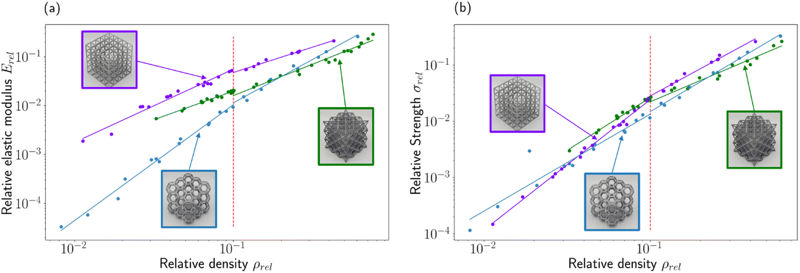 | ||
| Fig. 4 (a) Relative stiffness and (b) relative strength as a function of relative density. Best-fit exponents, expressed here as the slope of the plot on logarithmic axes, represent the structural efficiency of each geometry. The fits are computed separately with a relative density threshold of 10%, above which the contribution of the nodes to stiffness and strength can no longer be neglected. | ||
Effect of build-volume location on mechanical properties
An additional study is performed to isolate the effect of controllable packing parameters on the mechanical behavior of printed lattices. Specifically, two spatial parameters are studied independently: location within the print bed and print angle as measured relative to the build volume walls. To study the effect on printing location, 48 identical lattices (Kelvin unit cell; 75 mm specimen size; 2 mm nominal beam thickness; 15 mm unit cell size) are printed in a tessellated array in the build volume, all oriented parallel to the walls of the build volume. This specific geometry is chosen to ensure that the lattices would fail by fracturing and therefore attain a measurable ultimate compressive strength. The lattices are printed with equal spacing in four layers, each with twelve lattices; the lattices within each layer were arranged in a 4-by-3 grid, corresponding to the rectangular cross-section of the Jet Fusion 5200 printer build volume. Compression testing of the lattices yields a map of compressive strength and stiffness as a function of purely location. The measured data is shown in Fig. 5, with a linear interpolation performed on slices of the data, taken at constant values of the y print-volume coordinate, for visualization. In order to illustrate the relative differences between specimens, the modulus of each specimen is normalized to the average modulus of the entire cohort. Parts printed near the bottom of the build volume tend to exhibit higher strengths and stiffnesses. This effect is attributed to the thermodynamics of the print cooling period, after the build is complete and before it is unpacked for cleaning. During print cooling, heat is dissipated by convection to the ambient environment, which results in cooler temperatures near the external surfaces, such as the top, of the print volume.31 The parts printed near the exposed surfaces thus cool at a faster rate, leading to lower recrystallization of the PA-12 structure.32 As a result, these parts exhibit weaker mechanical properties. The density of the packed build and the relative location of solid parts, which act as thermal reservoirs, also affects the cooling profile of the build volume. The crystallinity of printed parts at a single height within the build volume may also vary due to these temperature differences.33 Therefore, local deviations appear in the strength and stiffness trends. Although this result demonstrates that printed parts at this scale are susceptible to location-dependent behavior, further study is required to characterize the reproducibility of the variance found in this dataset. For this reason, a random packing scheme was adopted for the other lattices printed in this work, such that the location-based variability is as stochastic as possible.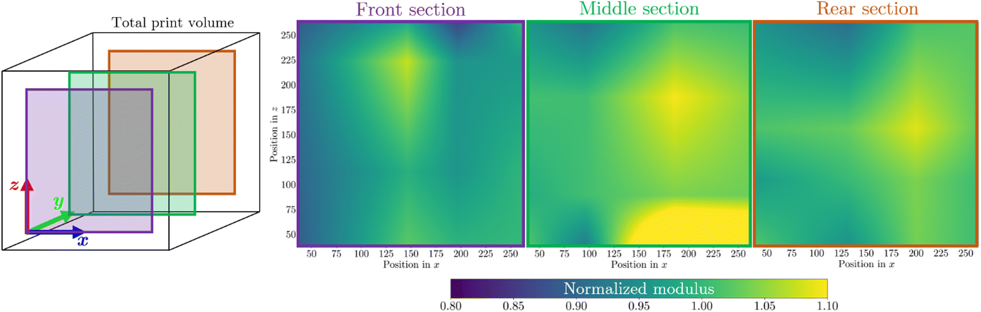 | ||
| Fig. 5 Location-dependent stiffness for a build volume containing tessellated specimens of the same geometry (Kelvin lattice). Stiffness values are normalized to the cohort average. Panels on the right show linearly interpolated data for various y-slices (see schematic at left), illustrating the variability of stiffness as a result of location-based differences in part cooling trends. | ||
Another potential method of further tuning mechanical properties that has been studied in the recent literature is the post-printing heat treatment (i.e., annealing) of finished parts. Annealing MJF-printed PA-12 has been shown to increase the percentage crystallinity, which increases both the ultimate strength and stiffness of parts but decreases the elongation at break,34 as expected for a semicrystalline polymer. However, for certain MJF-printed lattice geometries (e.g., Kelvin cells), the embrittlement of the material after annealing can have an adverse effect on the energy absorption of the structure, due to increased crack formation and propagation through the part.35 We hypothesize that selective annealing of printed parts could be a potential method of homogenizing variations in mechanical properties that originate from process-dependent parameters like build volume locations. For applications that prioritize stiffness or strength over ductility, specimens that are closer to the external surfaces of the build volume, which cool fastest, could be subjected to thermal annealing. At the same time, reheating samples could affect the dimensional accuracy of printed parts via thermal bleeding.36 For these reasons, the decision to heat-treat parts after printing should be application-specific.
Effect of printing angle on mechanical properties
Printing angle is another important packing variable that is known to affect the performance of printed parts, particularly for small part sizes. The effect of varying print angle is realized most clearly in the “stair-stepping” of individual 80-micron layers of material. For parts printed at shallow angles relative to the powder-spreading direction, the stair-stepping effect is greatest in magnitude, affecting both dimensional accuracy and mechanical properties. Additionally, the impact of stair-stepping is different for features of different nominal dimensions, because the stair-stepping effect is due to a fixed layer height used for all printed parts. To effectively capture this behavior as it relates to MJF-printed lattices, an independent group of 48 lattice specimens are prepared. In this cohort, the overall 75 mm specimen size and Kelvin geometry (chosen to capture both densification and fracture regimes) are held constant, but the beam thickness and unit cell size are varied to thoroughly measure the angle effect on beams of aspect ratios varying from 0.08 to 0.40. Parts are oriented at 0, 30, 45, and 60 degrees measured from the vertical axis of the build volume. To determine the effect of printing angle on measured stiffness, the theoretical elastic modulus for each specimen is calculated using the empirical relations in Table 4, considering slender and non-slender lattices separately, and compared to the measured elastic modulus. Strength is not used as a measure of mechanical behavior because the Kelvin cells display a mixture of fracture and densification behavior, the latter of which does not exhibit a meaningful ultimate strength. Rather, the distribution of the actual modulus, normalized relative to the predicted modulus, is computed for each printing angle (Fig. 6). The normalized data reveals that stiffness was not uniform across specimens printed at different angles; however, for both the slender and non-slender groups computed separately, there is no clear trend which would indicate a relationship between these variables. This result demonstrates that at larger scales, the hypothesized stair-stepping effect is diminished in terms of the overall impact on specimen performance. Furthermore, no statistically significant trend was found between beam dimensions or overall specimen dimensions and printing angle. Practically speaking, this demonstrates that in terms of printing angle, a throughput-maximizing packing procedure is sufficient for lattice-based geometries with regard to compressive stiffness.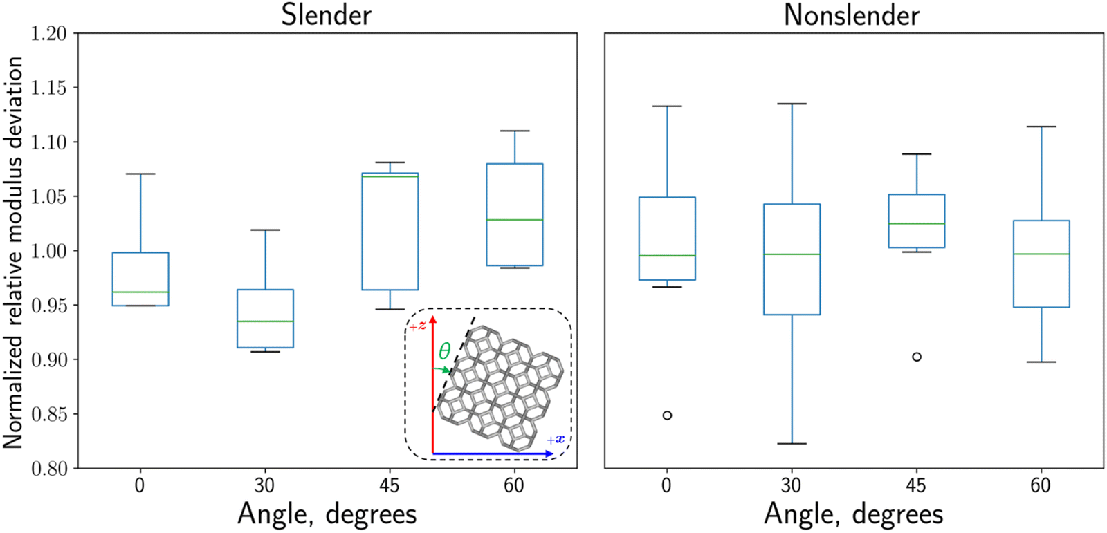 | ||
| Fig. 6 Angle-based stiffness trends. The printing angle, measured from the vertical, determines the amount of “stair-stepping” due to the layer-based fusion process. To isolate the effect of printing angle, measured stiffness values are normalized relative to predicted values obtained using the empirical scaling relationships for each specimen. Results are grouped based on slenderness; slender lattices have a relative density less than 10%. | ||
Discussion
Stiffness and strength scaling
In addition to the measured stress–strain characteristic of each specimen in compression, analysis of the empirical scaling constants for stiffness and strength obtained from the aggregate test samples offers insight into the load-transfer and failure behavior, respectively, of MJF-printed lattices. Specifically, for the stiffness relation, the exponent m describes each structure's tendency to behave like an ideal stretch-dominated lattice (m = 1) which carries only axial stresses or an ideal bending-dominated lattice (m = 2) which admits bending moments within beam elements.The octet structures overall tend toward stretch-dominated behavior, which is predicted for this geometry, but demonstrate a slight deviation from pure stretching behavior (m = 1.17 for the slender structures; m = 1.29 for the non-slender structures). This effect is likely due to the finite node-size effect, in which the diameter of the nodes affects the effective length and load transfer path of individual beam elements.17 It is likely that the nodes, having finite size and a rigid fixity, admit a nonzero amount of bending moment within each beam. Similarly, the non-slender Kelvin structures displayed mixed behavior (m = 1.78), this time trending closer to a stretch-dominated case compared to the predicted purely bending-dominated action. In comparison, the Kelvin structures having a slender aspect ratio have a high stiffness exponent (m = 2.37), indicative of bending-dominated behavior consistent with the low nodal connectivity of the structure. It is therefore reasonable to conclude that slender printed MJF lattices of very high and very low nodal connectivity behave consistently with behavior predicted by classical theory, yet the node-size effect is critical for non-slender structures, which begin to display mixed behavior.
In the case of the cubic structure, which has a moderate nodal connectivity, two distinct behaviors are observed depending on the structure's relative density. Slender cubic lattices display mixed behavior with m = 1.5 exactly, indicating that neither purely stretching nor bending governs the load transfer mechanism. Indeed, empirical results suggest that a third mode – buckling – controls the behavior of cubic cells, which have beams oriented exactly parallel to the applied compressive load. Furthermore, this buckling effect is more pronounced for the slender structures, which have smaller aspect ratios compared to their non-slender counterparts, because the critical buckling load is reached sooner. Indeed, the non-slender cubic lattices display almost purely stretching-dominated behavior (m = 1.04), indicating that the broader axially oriented beams are the most efficient (of any structure studied) at carrying load, at least until the delayed onset of buckling that causes their ultimate failure.
The scaling of relative compressive strength with relative density also highlights important features of the failure mechanisms of MJF-printed lattices. The octet samples display mixed behavior, having higher scaling exponents compared to first-principles theory associated with pure stretch-dominated failure. This suggests that even in the high-connectivity octet structure, individual beams are not loaded purely in tension or compression at the onset of failure. Rather, there is a component of force that contributes to an internal moment within the beam elements. Again, as observed in the stiffness data, this suggests that the node-size effect makes a significant contribution to how load is transferred among beams in this structure. Although the node size for a given beam thickness is fixed by design, this effect is noticeable even in the non-slender cohort (n = 1.26). The exponent of n = 1.88 associated with the slender specimens suggests not only that bending occurs, but also that the onset of buckling is reached in some beams prior to failure. This conclusion is not unreasonable, especially for thin beams of low aspect ratio, due to the orientation of beam elements with respect to the loading direction.
Kelvin structures displayed a near-constant strength scaling behavior regardless of slenderness, which is not predicted by theoretical arguments. The scaling exponents (n = 1.73, n = 1.75) suggest a mixed bending-buckling mode of failure, whereby individual beams (e.g. those oriented in a parallel direction to the applied axial compression) experience buckling, while others (e.g. perpendicular or angled beams) experience a bending moment. The absence of stretching behavior is also consistent with the low nodal connectivity of the Kelvin geometry, which results in very few beams experiencing pure tension, and therefore disallows failure by tensile rupture.
Cubic structures display slenderness-dependent behavior associated with the changing buckling-stress onset, as suggested by their stiffness data. Low-density, slender cubic structures are governed by the buckling mode (n = 2.32) as the critical stress for buckling is reached quickly during testing. However, the non-slender cubic structures display a mixed bending-buckling mode (n = 1.61), suggesting the delayed onset of buckling and rather the development of bending moments within some beam elements prior to failure.
Comparison to other material and manufacturing systems found in literature
The empirical relationships calculated for the MJF specimens in the present study show a degree of disagreement from the classical beam theory due to nonidealities in nodal connectivity. While this is expected, it is also of interest to contextualize the MJF system with other material and manufacturing systems, which may also be susceptible to similar results. A comparison to other material systems may also serve to isolate the effect of MJF-specific phenomena, such as the influence of porosity or other known process deviations, both in the bulk and on the surface of printed parts. Table 5 presents the scaling exponents for relative stiffness and relative strength as a function of relative density for several other systems from literature.| Geometry | Avg. nodal connectivity and failure mode | E′ = Cρm | σ′ = Dρn | Material system |
|---|---|---|---|---|
| Exponent m | Exponent n | |||
| Slender/non-sl. | Slender/non-sl. | |||
| Kelvin | 4, bending | 2.37/1.78 | 1.73/1.75 | MJF |
| 2.1 | Polycarbonate (simulation)37 | |||
| 1.56 | 1.83 | SLS (maraging steel)38 | ||
| 2.096 | Simulation39 | |||
| Octet-truss | 12, stretching | 1.17/1.29 | 1.88/1.26 | MJF |
| 1.91 | 1.86 | SLA (PR-48 resin)27 | ||
| 1.1 | Simulation37 | |||
| 1.46 | FDM (polylactic acid)40 | |||
| 1.23 | 1.32 | SLS (maraging steel)38 | ||
| Cubic | 6, “intermediate” behavior and buckling | 1.5/1.04 | 2.31/1.61 | MJF |
| 1.1 | Simulation37 | |||
| 0.904 | SLM (Ti6Al4V)41 | |||
| 0.93 | SLM (literature review)42 | |||
| 2.38 | FDM (polylactic acid)40 |
Compared to other macroscopic material systems studied in the literature, both as a result of simulation and of empirical testing (Table 5), good agreement is found for the MJF-printed lattice structures studied in the present work. This result suggests the arguments made about the studied lattice structures could be somewhat material-independent at a high level; yet important distinctions remain with respect to MJF-printed structures in particular. For example, the degree to which slenderness affects the scaling relationship of lattice stiffness and strength is important to characterize specifically for MJF-printed PA-12, because this variable is directly related to the scaling of bulk properties as a function of part geometry and packing variability. The scalability of these results with regard to overall part size, which is intrinsic in the collected dataset, is also an important consideration in order to utilize the large-format printing capabilities afforded by the MJF process.
Conclusions
The relationship between beam aspect ratio, relative density, stiffness, and strength is studied for three fundamental lattice structures of varying nodal connectivities: octet-truss, simple cubic, and Kelvin. For each geometry, the density scaling as a function of beam aspect ratio is first determined and compared to theoretical values, in order to capture and quantify the physical effect of process artifacts on printed lattices. Then, specimens are tested in uniaxial compression until failure to investigate load-transfer and failure mechanisms. In addition to load-displacement characteristics that describe the behavior of each structure under an applied stress, the compressive stiffness and ultimate compressive strength of each specimen is extracted from the data. The exponential scaling relationships of relative stiffness and relative strength as a function of relative density as described by Gibson and Ashby are used as a basis for fitting empirical data. Observing the trends that emerge in the data illustrates important structural attributes of each lattice geometry and further unveils the mechanisms of internal load distribution until failure. Results are compared to both the classical theory and existing material systems in the literature to contextualize nonidealities primarily relating to the finite geometry of lattice beams and nodes.Future work may extend this research to other MJF-printed materials like PA-11 or other thermoplastics in order to study and further contextualize trends as a result of process phenomena intrinsic to the MJF process. The effect of part-to-part spacing, build density, and other packing phenomena can also be explored to complement and extend the currently understood conclusions about printing angle and printing location-dependent mechanical properties. Finally, investigating fracture surfaces using advanced imaging methods like computed tomography (CT) scanning may reveal important characteristics about void defects in fused powder and their effect on mechanical performance. Although a more thorough depiction of the behavior of MJF-printed PA-12 may be obtained to further current understanding of process-driven properties, the empirical correlations established here between mechanical properties and tunable geometrical parameters can be applied to inform advanced topology-optimization routines that solve for geometry as a function of local stresses. In this way, large-scale structures can be specifically and efficiently tailored in the design phase to minimize weight while meeting critical performance specifications and be successfully realized at large scales using Multi Jet Fusion.
Conflicts of interest
The authors have no conflicts of interest to declare.Acknowledgements
We would like to acknowledge support from the 3D & Digital Manufacturing Lab of HP Labs, a division of HP, Inc. The authors would also like to express their gratitude for the technical assistance and guidance from the MJF Print Lab team and the Metrology team of HP Labs. Additionally, we would like acknowledge support from the Office of Naval Research (Fund Number: N00014-21-1-2604) and Army Research Office (Fund Number: W911NF-22-1-0175).References
- W. Gao, Y. Zhang, D. Ramanujan, K. Ramani, Y. Chen, C. B. Williams, C. C. L. Wang, Y. C. Shin, S. Zhang and P. D. Zavattieri, Comput.-Aided Des., 2015, 69, 65 CrossRef.
- Z. Jin, Z. Zhang, K. Demir and G. X. Gu, Matter, 2020, 3, 1541 CrossRef.
- N. Guo and M. C. Leu, Front. Mech. Eng., 2013, 8, 215 CrossRef.
- Z. Jin, Z. Zhang, J. Ott and G. X. Gu, Addit. Manuf., 2021, 37, 101696 Search PubMed.
- S. Lee, Z. Zhang and G. X. Gu, Mater. Horiz., 2022, 9, 952 RSC.
- R. Guerra Silva, M. J. Torres and J. Zahr Viñuela, Polymers, 2021, 13, 2163 CrossRef CAS PubMed.
- HP Development Company, L. P., 2018.
- H. Kim, Y. Zhao and L. Zhao, 2016 1st International Workshop on Cyber-Physical Production Systems (CPPS), IEEE, Vienna, Austria, 2016, pp. 1–4 Search PubMed.
- J. Riedelbauch, D. Rietzel and G. Witt, Addit. Manuf., 2019, 27, 259 CAS.
- B. Berman, Bus. Horiz., 2012, 55, 155 CrossRef.
- J. Šafka, M. Ackermann, F. Véle, J. Macháček and P. Henyš, Materials, 2021, 14, 2165 CrossRef PubMed.
- A. Y. Chen, A. Chen, J. Wright, A. Fitzhugh, A. Hartman, J. Zeng and G. X. Gu, Adv. Eng. Mater., 2022, 2100974 CrossRef CAS.
- C. Sharpe and C. C. Seepersad, J. Mech. Des., 2021, 143, 091708 CrossRef.
- Y. Tang, G. Dong, Q. Zhou and Y. F. Zhao, IEEE Trans. Automat. Sci. Eng., 2018, 15, 1546 Search PubMed.
- M. Eynbeygui, J. Arghavani, A. H. Akbarzadeh and R. Naghdabadi, Acta Mater., 2020, 183, 118 CrossRef CAS.
- T. Maconachie, R. Tino, B. Lozanovski, M. Watson, A. Jones, C. Pandelidi, A. Alghamdi, A. Almalki, D. Downing, M. Brandt and M. Leary, Int. J. Adv. Des. Manuf. Technol., 2020, 107, 4449 CrossRef.
- D. J. McGregor, S. Tawfick and W. P. King, Addit. Manuf., 2019, 25, 10 CAS.
- Y. Wang, C. Feng, Z. Zhang, D. Qian and Z. Song, Materials, 2022, 15, 3815 CrossRef CAS PubMed.
- M. F. Ashby, Philos. Trans. R. Soc., A, 2006, 364, 15 CrossRef CAS PubMed.
- S. Kechagias, R. N. Oosterbeek, M. J. Munford, S. Ghouse and J. R. T. Jeffers, Addit. Manuf., 2022, 54, 102730 CAS.
- J. Plocher and A. Panesar, Addit. Manuf., 2020, 33, 101171 Search PubMed.
- R. Alberdi, R. Dingreville, J. Robbins, T. Walsh, B. C. White, B. Jared and B. L. Boyce, Mater. Des., 2020, 194, 108883 CrossRef CAS.
- F. N. Habib, P. Iovenitti, S. H. Masood and M. Nikzad, Mater. Des., 2018, 155, 86 CrossRef CAS.
- A. P. Singh and S. Pervaiz, Advanced Manufacturing, American Society Of Mechanical Engineers, Virtual, Online, 2021, volume 2A, p. V02AT02A023.
- L. J. Gibson and M. F. Ashby, Cellular Solids: Structure and Properties, Cambridge Univ. Press, Cambridge, 2001 Search PubMed.
- C. M. Portela, J. R. Greer and D. M. Kochmann, Extreme Mech. Lett., 2018, 22, 138 CrossRef.
- L. R. Meza, G. P. Phlipot, C. M. Portela, A. Maggi, L. C. Montemayor, A. Comella, D. M. Kochmann and J. R. Greer, Acta Mater., 2017, 140, 424 CrossRef CAS.
- D. Weaire, J. Phys.: Conf. Ser., 2009, 158, 012005 CrossRef.
- V. S. Deshpande, N. A. Fleck and M. F. Ashby, J. Mech. Phys. Solids, 2001, 49, 1747 CrossRef CAS.
- X. Y. Chen and H. F. Tan, Int. J. Mech. Sci., 2018, 140, 279 CrossRef.
- H. W. B. Teo, K. Chen, V. T. Tran, H. Du, J. Zeng and K. Zhou, Polymer, 2021, 235, 124256 CrossRef CAS.
- M. Mele, G. Campana, G. Pisaneschi and G. L. Monti, Rapid Prototyp. J., 2020, 26, 1789 CrossRef.
- B. Sagbas, B. E. Gümüş, Y. Kahraman and D. P. Dowling, J. Manuf. Process., 2021, 70, 290 CrossRef.
- X. Liu, W. S. Tey, J. Y. C. Choo, J. Chen, P. Tan, C. Cai, A. Ong, L. Zhao and K. Zhou, Addit. Manuf., 2021, 46, 102205 CAS.
- M. Ali, R. K. Sari, U. Sajjad, M. Sultan and H. M. Ali, Addit. Manuf., 2021, 47, 102285 CAS.
- J. Chen, P. Tan, X. Liu, W. S. Tey, A. Ong, L. Zhao and K. Zhou, Virtual Phys. Prototyping, 2022, 17, 295 CrossRef.
- I. Arretche and K. H. Matlack, Front. Mater., 2018, 5, 68 CrossRef.
- O. Al-Ketan, R. Rowshan and R. K. Abu Al-Rub, Addit. Manuf., 2018, 19, 167 Search PubMed.
- D. A. Şerban, S. Sărăndan, R. Negru, G. Belgiu and L. Marşavina, IOP Conf. Ser.: Mater. Sci. Eng., 2018, 416, 012108 Search PubMed.
- A. Alam, K. Berube, M. Rais-Rohani and B. Khoda, 3D Print. Addit. Manuf., 2022 DOI:10.1089/3dp.2021.0207.
- J. Kadkhodapour, H. Montazerian, A. Ch Darabi, A. P. Anaraki, S. M. Ahmadi, A. A. Zadpoor and S. Schmauder, J. Mech. Behav. Biomed. Mater., 2015, 50, 180 CrossRef CAS PubMed.
- T. Maconachie, M. Leary, B. Lozanovski, X. Zhang, M. Qian, O. Faruque and M. Brandt, Mater. Des., 2019, 183, 108137 CrossRef.
| This journal is © The Royal Society of Chemistry 2023 |