 Open Access Article
Creative Commons Attribution 3.0 Unported Licence
Unraveling the effect of carbon nanotubes on the dielectric and mechanical properties of inorganic silica rich stone waste nanocomposites
Ashish Kumar
Chaturvedi
 ab,
Asokan
Pappu
ab and
Manoj Kumar
Gupta
 *ab
*ab
aCSIR – Advanced Materials and Processes Research Institute, Madhya Pradesh 462026, India. E-mail: mkgupta@ampri.res.in; manojampri@gmail.com; Fax: +91 755-2457042; Tel: +91 9977360351
bAcademy of Scientific and Innovative Research (AcSIR), Ghaziabad-201002, India
First published on 10th November 2022
Abstract
For the first time, a high performance carbon nanotube (CNT) reinforcement-stone waste polymer nanocomposite was fabricated using an epoxy matrix via the compressive molding route. The morphological, mineralogical, and functional group presented by the pristine stone waste and CNT-reinforced stone polymer nanocomposites were investigated by X-ray diffraction (XRD), scanning electron microscopy (SEM), and Fourier transformed infrared spectroscopy. Strong interfacial bonding between stone waste, carbon nanotubes, and epoxy polymer was achieved through the polar dimethylformamide (DMF) solvent and through the high energy ball milling process. The dielectric constant drastically increased with an increase in CNTs in the stone waste-epoxy matrix. Very high dielectric constant up to 1800 was achieved for the 0.2 (wt%) CNT-filled stone waste sample, whereas the pristine stone composite exhibits a low dielectric constant of 26. It was found that the stone waste nanocomposites with a higher CNT content produced a lower dielectric constant. CNT-filled nanocomposites showed high flexural strength and tensile strength of 77 MPa and 20.78 MPa, respectively, for the 0.2% filled CNT nanocomposites. However, at high filler concentrations, both flexural and tensile strength decreased. The results were analyzed in terms of interfacial bonding, polar solvent, and sudden increase in the polarization, improved bonding, and agglomeration tendency of the CNTs.
1. Introduction
The improper disposal of industrial inorganic wastes such as stone waste is a worldwide problem. Due to the continuous demand of stones, the quantity of stone wastes generated during various industrial/mining, cutting, querying, sawing, and polishing processes from limestone industries increased to about 16 MT per year.1,2 For the utilization of the stone waste produced under various processes, a large amount of dust is produced and dumped in open land, which causes different environmental problems including greenhouse effect and health-hazardous issues such as cancer, lung problems, and heart diseases.3 The non-biodegradability of stone waste further increased the severity of the problem.4 Usually, the stone contains different minerals such as calcite (CaCO3), dolomite (CaMg(CO3)2), and silicon oxide (SiO2). Moreover, it also contains several heavy metals, which further contaminate the ground water quality, leading to health issues.5 Therefore, searching viable alternatives to utilize stone waste is urgently needed. Recently, stone waste is used as a filler in cement and bricks, and to prepare aluminum alloy composites.6 Stone waste has been also used to fabricate the hybrid composite sheet in the polymer for building and infrastructure applications.7,8 However, the strength of the stone-based nanocomposite was not high, which restricts their practical applications in various sectors including aerospace, automobile, and building materials.9 Moreover, to use them as electrical insulating materials in various sectors, high dielectric constant is required.10,11 To tune these properties in polymer nanocomposites, various nanomaterials such as graphene, carbon nanotubes, silver nanoparticles, and metal oxide nanostructures have been recently used.12,13 In addition, Huang et al. used artificial marble as a filler to enhance the mechanical strength of the poly(vinyl alcohol) (PVA) via supramolecular interfacial interaction and plasticization strategy.14 Zhang et al. also improved the mechanical properties of high-density polyethylene/artificial marble wastes composites using the titanate coupling agent prepared by modulating the interfacial strength.15Moreover, the hybrid nanocomposites have been widely utilized for fabricating numerous advanced applications such as shape memory/self-healing devices, electrical insulators, piezoelectric/triboelectric nanogenerators, flexible and wearable electronics, structural health monitoring, self-powered nanosensors, soft robotics, aerospace, intelligent systems, and for the fabrication of advanced construction materials.16–19
Among various nanofillers, CNTs have been used as a novel filler to improve the mechanical, physical, chemical, and electric properties of the nanocomposite.20,21 CNTs are composed of sp2 carbon networks, and their unique tubular structure make them wonderful materials with excellent chemical, physical, and mechanical properties.20,21 Recently, CNTs have been utilized in numerous applications such as potential probes for bioimaging, neurosensory, super capacitors, solar cells, and nanogenerator sectors.18,22–24 However, CNTs have not been used as the filler to fabricate the stone-CNT nanocomposites. The effect of the CNT on their mechanical and dielectric properties is also not reported yet. However, the dispersion of the CNTs in the stone waste polymer matrix is very critical due to the high surface energy and controlling their agglomeration in polymer composites is still a great technical challenge. Recently, C3H7NO =![[thin space (1/6-em)]](https://www.rsc.org/images/entities/char_2009.gif) N,N′-dimethylformamide, a colorless polar solvent that is a natural, has been widely used to increase the dispersion and interfacial strength of the CNT with the polymer matrix.
N,N′-dimethylformamide, a colorless polar solvent that is a natural, has been widely used to increase the dispersion and interfacial strength of the CNT with the polymer matrix.
In the present work, we have successfully fabricated CNT-reinforced stone waste nanocomposites samples through compressive moulding routes, and the dispersion of the CNTs in the epoxy-stone matrix polymer is achieved through the polar solvent and high energy ball milling process. Various polymer nanocomposites with various CNT filler concentrations (0.1, 0.2, 0.3, and 0.4 wt%) were developed. The dielectric constant and mechanical properties of the CNT-reinforced stone waste nanocomposites were analyzed. The results were analyzed in terms of interfacial bonding, polar solvent, and sudden increase in polarization and improved bonding.
2. Experimental details
Fabrication details of CNT-stone particulates nanocomposites
Multiwalled carbon nanotubes were purchased from Nano Research Element, India (radius of 5–15 nm). Inorganic stone waste particulates were collected from Khajuraho, located at Chhatarpur, MP state, India. Initially, stone waste was ground and washed several times with DI water and dried at 70 °C in air. The CNTs with amount 0.1%, 0.2%, 0.3%, and 0.4% (wt%) were taken and mixed with the stone waste particulates. The resultant powder was ball milled using high energy planetary ball milling condition for 7 h at 240 rpm condition. The polar solvent DMF was used as the dispersion medium. To prepare the nanocomposite, epoxy and hardener purchased from Atul Ltd, India were used as the polymer, and the ball milled CNT-stone waste was mixed and stirred at RT for 5 h. The mixed solution was poured in the compressive mold cavity and a pressure of 110 MPa was applied at room temperature for 24 h. The CNT-reinforced stone-nanocomposite sheet was received after demolding. The whole fabrication process is displayed in Fig. 1a and the actual photograph of the fabricated CNT-stone waste nanocomposite is displayed in Fig. 1b.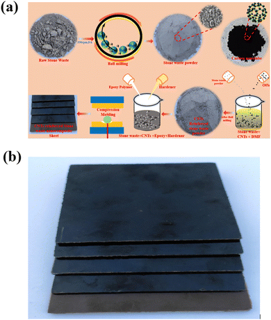 | ||
| Fig. 1 (a) Schematic fabrication process of carbon nanotube-reinforced stone waste epoxy polymer composite. (b) Carbon nanotube-reinforced composite sheet. | ||
Characterization and measurements
The X-ray diffraction of the stone particulate sample was investigated to identify its mineral and crystalline nature by a Rigaku-Mini Flex II in the 2 theta range of 10–75 degrees. The elemental analysis of stone waste was carried out using wavelength dispersive X-ray fluorescence spectrometry (Bruker, S8, Tiger, Germany). The surface morphologies of carbon nanotube-reinforced stone waste polymer nanocomposite were recorded using a scanning electron microscope (SEM). A ThermoScientific Nicolet iS50 FT-IR spectrometer was used to determine the functional groups of the sample. The transmission electron microscopy (TEM) image of the sample was recorded using a JEOL JEM-F200 (Tokyo, Japan). The dielectric properties of the CNT-stone nanocomposites were investigated by a Keysight LCR meter (E4980A) at room temperature. The flexural strength and tensile strength of the samples were measured using a universal testing machine (Lloyd LRX Plus, UK) at room temperature.3. Results and discussion
X-ray diffraction and X-ray wavelength dispersive X-ray fluorescence analysis
The XRD results of the as-received stone waste powder was recorded in the two-theta range from 10 to 75 degrees. XRD was used to qualitatively determine the elements and compounds present in the stone waste, and the mineral phase was confirmed using the JCPDS number and their peak position (Fig. 2a). The XRD result of the stone waste reveals that stone waste has five major different mineral phases, including muscovite (KAl2(Si3Al)O10(OH,F)2 [JCPDS card: 07-0042], actinolite (Ca2(Mg,Fe)2Si8O22(OH)2) [JCPDS card: 80-052], calcite (CaCO3) [JCPDS card: 5-586], dolomite (CaMg(CO3)2 [JCPDS card: 36-0426], and quartz (SiO2) [JCPDS card: 46-1045] phases. It is seen that the main and highly intense peak observed at about 26.6° corresponds to the quartz phase. The XRD result also reveals the high amount of Ca-rich mineral phase actinolite in the stone waste.25,26 The sharp XRD peaks show the polycrystalline nature of the stone waste, which help to increase the mechanical properties of the nanocomposites. The elemental analysis of the inorganic stone waste was carried out using the WD-XRF technique. Stone waste contains 77.10% SiO2, 14.30% Al2O3, 5.59% K2O, 4.11% Na2O, 2.33% Fe2O3, and 1.06% MgO. CaO, TiO2, ZrO2, and BaO were also presented in the stone waste with an amount of 0.59%, 0.25%, 0.16%, and 0.12%, respectively (Fig. 2b). In addition, few elements such as SO3 MnO, SrO, Y2O3, ZnO, CuO, and NiO were observed in very minute concentrations in the ppm range (Fig. 2c). In addition, various parameters such as pH value, bulk density, specific gravity, conductivity, and porosity of stone waste powder were measured and calculated as per standard procedures, and the results are presented in Table 1.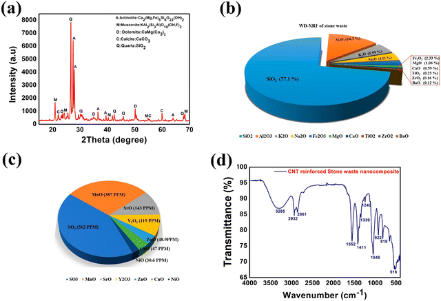 | ||
| Fig. 2 (a) XRD of CNT-reinforced stone waste polymer nanocomposite. (b and c) XRF results of the stone waste. (d) FTIR of CNT-reinforced stone waste polymer nanocomposite. | ||
| S no. | Parameter | Value |
|---|---|---|
| 1 | pH | 6.51 ± 0.07 |
| 2 | Bulk density (g cm−3) | 1.03 ± 0.02 |
| 3 | Specific gravity | 2.57 ± 0.06 |
| 4 | Electrical conductivity (μS cm−1) | 73.14 ± 0.24 |
| 5 | Porosity (%) | 59.80 ± 1.22 |
Functional group studies
The functional groups present in the CNT-stone nanocomposite sample were investigated by recording the FTIR spectrum in the range of 500–4000 cm−1 wavenumber (Fig. 2d). The absorption peaks at 2932 cm−1 and 2861 cm−1 are due to the asymmetrical C–H stretching of the –CH3 group and –CH2 group, respectively.27,28 The peaks at 1552 cm−1 and 1411 cm−1 are due to aromatic C–C stretching vibration. The absorption band at 1339 cm−1 is attributed to asymmetrical –CH2 deformation. The absorption peaks at 1240 and 1048 cm−1 are related to the asymmetrical aliphatic C–O stretching and asymmetrical aromatic C–O stretching, respectively. The FTIR absorption band at 818 cm−1 is due to the –CH out-of-plane aromatic deformation.24,27 The characteristic peak of the CNT is also observed in the sample.Morphological studies
To fabricate the nanocomposites, CNT was mixed at various concentrations with the ball milled stone waste particulates and nanocomposite samples, as discussed in the Experimental section (Fig. 1a). Stone waste is randomly distributed in the epoxy matrix. The morphological investigation of the stone waste and prepared CNT-stone nanocomposites was carried out using SEM. Fig. 3a and b represent the low and high magnification surface morphologies images of the inorganic stone waste powder, respectively, as determined by the SEM technique. Fig. 3a and b depict an irregular morphology of the inorganic stone waste powder with the size ranging from 500 nm to 5.0 μm. Fig. 3c shows the transmission electron microscopy (TEM) image of CNTs, which was used as a reinforcement element with the stone-epoxy matrix. A well-defined tube-like morphology with a diameter of about 10 nm was observed for CNT. The SEM technique has been also widely used to analyze the relation of the stiff nature of the materials by the examining the interfacial strength/bonding of the polymer with the waste/CNT sample at the nanoscale level. The close view of the surface morphology confirmed the interfacial bonding of the as-prepared CNT-stone nanocomposite sheet (Fig. 3d). The results indicated the uniform/proper distribution of the CNT in the epoxy matrix and a strong bonding of the CNTs with stone particulates. Moreover, no porous structure or voids are visible in the sample.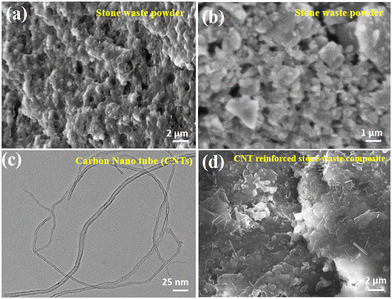 | ||
| Fig. 3 (a and b) SEM image of the stone waste powder sample. (c) TEM image of the CNT and (d) stone waste polymer nanocomposite sample. | ||
Mechanical strength studies
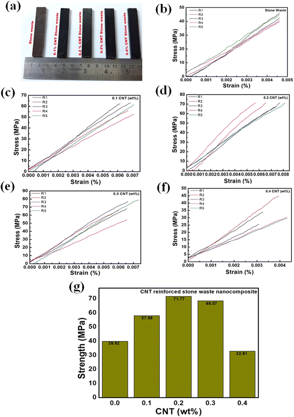
The flexural strength of CNT-stone nanocomposites was measured using UTM as per the ASTM D790-17 standard. To measure the flexural strength, five specimens of each sample, i.e., pristine stone waste composite and CNT-stone nanocomposite, were tested under the same conditions. The obtained flexural strength of pristine and CNT-reinforced stone waste sample with different filler concentrations are presented in Fig. 4. The flexural strength of the pristine stone waste polymer composite prepared using epoxy resin was found to be 39.92 ± 3.02 MPa. The stone waste polymer nanocomposite reinforced with 0.1, 0.2, 0.3, and 0.4 (wt%) of CNT show a flexural strength of 57.98 ± 1.15, 71.77 ± 1.68, 68.57 ± 1.03, and 32.91 ± 1.28 MPa, respectively. It is interesting to observe that, initially, the flexural strength of the CNT-filled nanocomposite increased with the increasing content of the CNTs in stone waste powder up to 0.2%; however, the flexural strength was reduced above 0.2 wt% of the CNT. The stress-strain curves measured for pure stone and CNT-stone waste composites and their replication are shown in Fig. 4b, c, d, e, and f, respectively. Fig. 4g shows the actual graph of flexural strength. Fig. 4g clearly shows that the enhancement in the flexural strength of the CNT-stone nanocomposite may be due to the outstanding mechanical properties of the CNT and excellent interfacial bonding between the CNTs and stone waste-epoxy resin. It is worth pointing out that due to the use of the DMF polar solvent in the CNT-stone waste and the introduction of DMF solvent during the ball milling process, the effective and strong adhesion of CNT to the stone waste and epoxy chains was promoted, which contributed to the high dispersion of CNT. This effectively reduced the van der Waals forces among CNTs with epoxy matrix, which result in a decrease in the agglomeration tendency of the CNT, while the functional groups enhanced the interactions with the DFM molecule. Strong interfacial interaction among CNT, stone waste, and epoxy polymer during ultrasonic treatment in polar DMF is expected due to the presence of a larger rough larger specific surface area of stone waste caused by their reduced particle size under the energy ball milling process. Moreover, polar DMF solvent is also adsorbed on the surface of carbon nanotubes through hydrophobic/π–π interaction and ultrasonication process, which helped DMF to debundle the CNTs by coulombic or hydrophilic interaction, leading to the overcoming of the van der Waals forces among the individual nanotubes and increase in the interfacial strength. In addition, the alkyl chains between stone waste and epoxy may also serve as the connection force to increase the dispersion rate, thus improving the interfacial interaction.14,15Therefore, these cause the CNTs to impart stiffness to the nanocomposite, which enhanced the flexural strength. However, for the CNT-stone nanocomposite with a CNT amount higher than 0.2%, the flexural strength decreased, which may be due to the agglomeration of CNT in the nanocomposite matrix.
The tensile strength defines the ability of a material to withstand a pulling (tensile) force, which is related to the amount of load or stress that can be handled by the sample before it stretches and breaks. The influence of the CNT reinforced in the stone waste polymer nanocomposite on the tensile strength is also investigated. The tensile strength is measured using the UTM machine as per the ASTM standard. Fig. 5a shows the tensile testing sample. Pristine stone waste composite shows a tensile strength of 7.98 ± 2.02 (Fig. 5b), whereas the CNT-reinforced nanocomposite (0.1, 0.2, 0.3, and 0.4 (wt%) shows 12.59 ± 1.25, 20.78 ± 1.68, 17.38 ± 1.03, and 15.58 ± 1.38 MPa, respectively (Fig. 5b). The tensile strength of CNT-reinforced stone waste nanocomposite was improved significantly with the addition of the CNT for 0.1 and 0.2 wt% CNT; however, the tensile strength reduced for 0.3 and 0.4% CNT. However, the tensile strength of the CNT filler with a concentration of 0.4% was still higher than pristine stone waste nanocomposites. The results also showed a similar trend with the flexural strength results. The enhancement in the tensile strength (ρnc) may be related to increased interfacial bonding between the CNTs and the stone-polymer matrix.
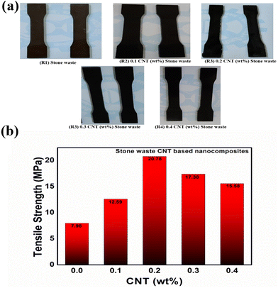 | ||
| Fig. 5 (a) Original image of tensile strength test samples. (b) Tensile strength of pristine and CNT-reinforced stone waste nanocomposite samples. | ||
Dielectric constant and dielectric loss of CNT-stone nanocomposites
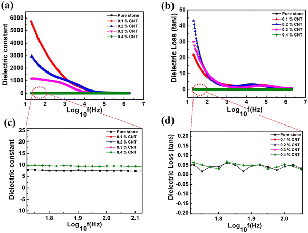
The dielectric properties of the stone waste composite and CNT-stone nanocomposite were measured by a Keysight LCR meter (E4980A). To measure the dielectric constant, a specimen with size of 12 mm × 12 mm with a thickness of 1.2 mm was prepared and silver was used as the electrode. The dielectric constant of the pristine and CNT-stone nanocomposite samples was measured in the frequency range of 20 Hz–2 MHz (Fig. 6a). The dielectric constant of pure and CNT filled nanocomposite sheets gradually reduced with the increase in the applied ac frequency, which is in accordance with the polarization relaxation of the electric dipoles.27 With the increase in the frequency, the polarization of the inner electric dipoles was unable to keep pace with the rapid change in the high frequency; thus, polarization weakens and the resulting dielectric constant decreases at the high frequency side. The dielectric constant of the stone waste polymer nanocomposite sheet was about 26 at 100 Hz; however, it was interesting to note that the dielectric constant increased several times for the CNT-reinforced stone waste nanocomposite sheets. The dielectric constant of the CNT-reinforced stone waste was found to be 3045, 4237, 765, and 26 at 100 Hz for CNT filler with 0.1, 0.2, 0.3, and 0.4 wt% concentration, respectively. A drastic enhancement in the dielectric constant value for 0.1 and 0.2 wt% CNT reinforcement in the stone waste nanocomposite was observed. An enlarged view of the dielectric constant and dielectric loss of the pristine and 0.4 wt% CNT-reinforced nanocomposites samples are given in Fig. 6c and d, respectively. The dielectric constant of the 0.2 CNT-filled sample was about 160 times higher than that of the pristine composite sample. With a further increase in the CNT, i.e., for 0.3 and 0.4 wt%, the dielectric constant starts to decrease and reaches a low value of 26. The increase in the dielectric constant was attributed to a sudden increase in the number of electric dipoles per unit volume owing to the nanoscale size of the CNT in the matrix. The increased interfacial polarization between the CNT, stone waste particulates, and epoxy polymer led to an increase in the dielectric constant. However, after 0.2 wt% of the CNT filler, the decrease in the dielectric constant was on account of the formation of the CNTs conductive network in the polymer matrix. It is worth pointing out that near the percolation threshold of 0.2 wt%, the dielectric constant value of the stone waste nanocomposites can be increased by several orders of magnitude, according to the Maxwell–Wagner (MW) polarization theory and building up of an interconnected carbon nanotube network in the matrix.25 However, it was proposed that poor CNT dispersion at high CNT content in the stone waste nanocomposite leads to the formation of clusters and agglomeration, which reduce the dielectric constant. We have also measured the dielectric tangent loss of the pristine and CNT-stone nanocomposite sheets under the same frequency range. Fig. 6b shows that dielectric loss also decreased with the increase in the frequency. The value of the dissipation factor is low for the pristine stone waste composite; however, dielectric loss increased to 27.92, 30.53, 43.5, and 8.00 for 0.1, 0.2, 0.3, and 0.4 CNT wt% reinforcement, respectively. The increase in the dissipation factor with CNT reinforcement is due to the high thermal conductivity of the CNT as compared to the stone waste and polymer matrix. In addition, the formation of the chain-like interconnected structure of CNT in the stone waste polymer matrix may increase the conductivity; thus, heat dissipation occurred.4. Conclusion
In conclusion, we have prepared a CNT-reinforced stone waste nanocomposite for the first time through an ecofriendly and cost-effective method. The structural, elemental, functional, and morphological investigation of the CNT-reinforced stone waste nanocomposites waste are investigated. The effect of various CNT amounts on the mechanical strength such as flexural strength and tensile strength of the stone waste nanocomposite were analyzed in terms of the dispersion of CNT in the matrix. The flexural and tensile strength of the stone nanocomposites were increased up to 0.2 wt% CNT and then the strength decreased. However, the mechanical strength was higher for the case of the CNT-reinforced composite as compared to the pristine stone nanocomposite. A very high dielectric constant ∼4500 was observed from the CNT-filled stone nanocomposite as compared to the low dielectric constant of the pristine stone composites. A dramatic increase in the dielectric constant and flexural strength was discussed in light of the CNT properties, interfacial polarization, and formation of nanodipoles in well-dispersed CNT in DMF solvent. High dielectric constant, flexural strength, and tensile strength made these materials as attractive alternative nanocomposite systems for manufacturing aircraft body parts, automobiles industries, flame retardant materials, self-hilling, and ecofriendly materials for numerous advanced applications.Conflicts of interest
There are no conflicts to declare.Acknowledgements
Authors are very thankful to Dr A. K. Srivastava, Director, CSIR-AMPRI, Bhopal for permitting the publication of the work. The authors are thankful to Mr Ravi Patidar and Dr Edwerd Peters for collecting the raw materials. Dr M. K Gupta is grateful to CSIR, India for granting MLP -305 and CSIR Young Scientist Award OLP 201 projects and CSIR Raman Research Fellowship award. Mr Ashish is thankful to AICTE for his fellowship.References
- N. Almeida, F. Branco and J. R. Santos, Build. Environ., 2007, 42, 810–819 CrossRef.
- A. Pappu, V. K. Thakur, R. Patidar, S. R. Asolekar and M. Saxena, Curr. Opin. Green Sustainable Chem., 2018, 13, 91–101 CrossRef.
- R. Kaur and P. Pandey, The Role of Climate and Air Pollution in Human Health and Urban Chemistry in Asian Cities, 2022 Search PubMed.
- A. Rana, P. Kalla, H. Verma and J. Mohnot, J. Cleaner Prod., 2016, 135, 312–331 CrossRef.
- K. H. Vardhan, P. S. Kumar and R. C. Panda, J. Mol. Liq., 2019, 290, 111197 CrossRef CAS.
- V. Gautam, A. Patnaik and I. Bhat, Advances in Manufacturing Systems, Springer, 2021, pp. 109–122 Search PubMed.
- A. Pappu, R. Chaturvedi, P. Tyagi, A. K. Khan, R. Patidar and E. Peters, Productivity, 2019, 60, 239–249 CrossRef.
- P. Sormunen and T. Kärki, J. Build. Eng., 2019, 24, 100742 CrossRef.
- S. Valvez, A. Maceiras, P. Santos and P. N. Reis, Materials, 2021, 14, 845 CrossRef CAS PubMed.
- Z. Ahmad, Dielectric material, IntechOpen, 2012 Search PubMed.
- Y. Rao, S. Ogitani, P. Kohl and C. Wong, J. Appl. Polym. Sci., 2002, 83, 1084–1090 CrossRef CAS.
- F. S. A. Khan, N. Mubarak, M. Khalid, M. M. Khan, Y. H. Tan, R. Walvekar, E. Abdullah, R. R. Karri and M. E. Rahman, Crit. Rev. Solid State Mater. Sci., 2021, 1–28 Search PubMed.
- H. Lu, J. Wang, M. Stoller, T. Wang, Y. Bao and H. Hao, Adv. Mater. Sci. Eng., 2016, 2016, 4964828 Search PubMed.
- X. Huang, Q. Guo, P. Zhou, C. Lu, G. Yuan, Z. Chen and X. Zhang, Composites, Part B, 2020, 182, 107628 CrossRef CAS.
- H. Lu, K. Chen, X. Yang, J. Liu, X. Huang, Z. Lv and X. Zhang, J. Vinyl Addit. Technol., 2021, 27, 137–146 CrossRef CAS.
- Y. Li, X. Huang, L. Zeng, R. Li, H. Tian, X. Fu, Y. Wang and W.-H. Zhong, J. Mater. Sci., 2019, 54, 1036–1076 CrossRef CAS.
- Z. Yang, Z. Zhu, Z. Chen, M. Liu, B. Zhao, Y. Liu, Z. Cheng, S. Wang, W. Yang and T. Yu, Sensors, 2021, 21, 8422 CrossRef CAS PubMed.
- P. Jiao, Nano Energy, 2021, 88, 106227 CrossRef CAS.
- Y. Chen, X. Pu, M. Liu, S. Kuang, P. Zhang, Q. Hua, Z. Cong, W. Guo, W. Hu and Z. L. Wang, ACS Nano, 2019, 13, 8936–8945 CrossRef CAS PubMed.
- A. D. de Oliveira and C. A. G. Beatrice, Nanocomposites-Recent Evolutions, 2018, pp. 103–104 Search PubMed.
- X. Qu, Y. Liu, Z. Liu and Z. Li, J. Phys. Mater., 2021, 4, 034015 CrossRef CAS.
- M. N. Amin, K. Khan, M. U. Saleem, N. Khurram and M. U. K. Niazi, Sustainability, 2017, 9, 1178 CrossRef.
- L. Muhmood, S. Vitta and D. Venkateswaran, Cem. Concr. Res., 2009, 39, 102–109 CrossRef CAS.
- S. Yoshida, Polym. J., 2014, 46, 430–434 CrossRef CAS.
- P. Maity, S. V. Kasisomayajula, V. Parameswaran, S. Basu and N. Gupta, IEEE Trans. Dielectr. Electr. Insul., 2008, 15, 63–72 CrossRef CAS.
- R. Yadav, M. Tirumali, X. Wang, M. Naebe and B. Kandasubramanian, Def. Technol., 2020, 16, 107–118 CrossRef.
- L.-C. Tang, H. Zhang, S. Sprenger, L. Ye and Z. Zhang, Compos. Sci. Technol., 2012, 72, 558–565 CrossRef CAS.
- T. Hanai and K. Sekine, Colloid Polym. Sci., 1986, 264, 888–895 CrossRef CAS.
| This journal is © The Royal Society of Chemistry 2023 |

