 Open Access Article
Creative Commons Attribution 3.0 Unported Licence
A simulation study of mega electron-volt helium ion channeling and shadow effect in titania nanotubes†
Jayahansa
Napagoda
 ab,
Quark Yungsung
Chen
ab,
Arti
Rani
ab,
Gemunu
Gunaratne
ab,
Quark Yungsung
Chen
ab,
Arti
Rani
ab,
Gemunu
Gunaratne
 a,
Di
Chen
 *ab,
Oomman K.
Varghese
 *ab and
Wei-Kan
Chu
*ab
aDepartment of Physics, University of Houston, Houston, TX 77204-5005, USA. E-mail: dchen33@central.uh.edu; okvarghe@central.uh.edu; wkchu@central.uh.edu
bTexas Center for Superconductivity, University of Houston, Houston, TX 77204, USA
First published on 26th November 2022
Abstract
Ion channeling refers to the guided motion of high energy ions through axial/inter-planar regions in single crystals and ordered nanostructures under the influence of the Coulomb scattering process. The process has the potential of focusing ion beams without the use of strong magnetic fields. While the channeling phenomenon in single crystal materials has been extensively explored, in recent years, there has been an increasing interest in using ordered nano-architectures, especially the nanotube structure, due to potential technological benefits. Here, we report a simulation study of He ion channeling in titanium dioxide (titania; TiO2) nanotubes with features similar to those fabricated using anodic oxidation. The anodic titania nanotubes stand out from the rest of the compound nanotubes owing to the ability to yield single nanotubes as well as vertically aligned nanotube arrays with dimensions tunable in a wide range to facilitate the desired effect from ion channeling. We explored mega electron-volt (MeV) He++ ion channeling in titania nanotubes through molecular dynamics simulations based on Lindhard's planar channeling potential. Our simulated trajectories of ions projected into titania nanotubes showed that ion channeling phenomenon could occur in straight nanotubes. The simulation results showed that ion channeling in titania nanotubes could be used to focus an ion beam to an area as small as 113 nm2 with a nanotube of pore diameter 100 nm. The distance to the first focal point reduced with the use of higher atomic number particles for channeling. We studied the transmittance of He ion flux through tilted nanotubes and compared the variation of the transmittance of ion flux under the ion channeling effect to that of a hypothetical beam following geometric optics, as a function of the angle of incidence. We introduced the term “Shadow Effect” to describe the variation of the transmittance of the above-mentioned hypothetical beam. For nanotube aspect ratios >20, the transmittance under ion channeling effect surpassed that in the case of the hypothetical beam.
I. Introduction
When energetic, charged particles are incident on monocrystalline materials at nearly parallel angles along major crystalline axes or between major crystalline planes, the Coulomb scattering process between the charged particles and the collective string or the sheet of target atoms on a plane steers them through the channels between the atoms. This process is called ‘Axial Channeling’ if the influence is from a string of atoms or ‘Planar Channeling’ if the steering process arises due to the planes of atoms.1,2 Ion channeling effect in typical crystalline materials has been well understood over the past decades due to its importance in solid state materials research.3 The ion channeling process combined with Rutherford Backscattering spectrometry is used as a standard tool to investigate the properties of crystals and their impurity locations of which the details cannot be extracted using other methods, for example, X-ray diffraction.4–8While the majority of the earlier channeling studies were focused on single crystal materials, nanotubes and ordered nanoporous structures have captured interest in recent decades after the discovery of carbon nanotubes.9–15 Pores (voids) of size a few to hundreds of nanometers surrounded by dense walls make the channeling process through these architectures distinct from that in single crystals with Angstrom scale inter-planar spacing.16–18 Consequently, these nanostructures have a higher beam acceptance. A large void with a potential localized very close to the walls can create a large potential gradient directed away from the wall driving the ions away from the wall and reducing the chances of de-channeling.
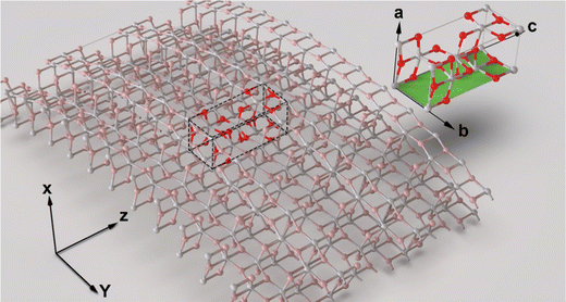 | ||
| Fig. 1 The structure of the unit cell of the anatase phase of TiO2. Only the b–c plane is assumed to interact with the ions moving through the nanotube pores. | ||
Since the discovery of carbon nanotubes, the material has been a hotspot of ion channeling studies due to its exceptional properties.19–22 For example, a particle beam channeled in a nanotube could be efficiently steered. However, the scope of studies on carbon nanotubes was limited. This is primarily due to the fact that the narrow pore size of carbon nanotubes and the low atomic number of carbon reduces the channeling probability. On the other hand, the nanotubes of compound semiconductors, particularly metal oxides, offer unique opportunities for conducting investigations on a wide range of material parameters, thus broadening the scientific knowledge.23 A few of the metal oxide semiconductors could be fabricated with inexpensive, scalable processes. Titanium dioxide (titania) is one such low cost material that finds applications in commercial products ranging from cosmetics, paints and food materials to electronics and photovoltaics.24 The presence of oxygen and titanium, a transition metal, with well-separated atomic numbers 8 and 22 respectively and the possibility of fabricating its nanotubes in a wide range of dimensions make this material scientifically intriguing for channeling studies. Titania nanotubes can be fabricated using both template assisted and template free processes.25 Hydrothermal and electrochemical anodization are the two primary techniques used for self-assembled titania nanotubes. While hydrothermal processes yield dispersed nanotubes, anodization produces vertically oriented nanotube array films. Titania nanotubes of length up to several hundred microns, pore diameter a few to several hundred nanometers and wall thickness a few to a few tens of nanometers can be fabricated using these techniques.18,26,27 Furthermore, the parallel geometry of titania nanotubes prepared by anodization is crucial for observing the ion channeling effect.
Our molecular dynamics simulation studies shows that channeling could be accomplished through titania nanotube arrays with features similar to those prepared by anodic oxidation. The channeling property of titania nanotubes would enable them to produce nanoscale ion beams and serve in place of giant magnets used for beam guiding.20,21 The nano scale ion beams produced using titania nanotubes could be used in various radiation and plasma technologies, as well as in biological studies and medical therapy.28 In radiation therapy, the charged particle beams guided through nanotubes could be focused strictly on cancer affected regions.22 Due to the property of ion channeling, the nanotube array films could also serve as masks in ion implantation. During ion beam implantation, ions spread all over the exposed area randomly. Nevertheless, when a nanoporous or nanotube array film is placed on the top of the area in which ions are implanted, instead of being randomly spread, ions end up making isolated impact sites.29 In order to verify the channeling effect in titania nanotubes, we simulated the propagation of high energy doubly ionized helium ions incident at various angles on titania nanotubes of pore diameter ∼100 nm. We report here the results of this work.
II. The model
After an ion enters the void of a titania nanotube, it is subjected to the Coulomb interactions with many atoms on the wall of the nanotube. The greater the distance between the ion and the atoms on the wall, the lesser the influence on the ion's motion due to their interaction. Effectively, the ion interacts with atoms which can be assumed to be on a plane without a curvature. For studying the ion channeling effect in titania nanotubes using molecular dynamics simulations, we postulated that Lindhard's planar continuum potential1 would be valid in the void of a nanotube. Lindhard's continuum model for planar channeling uniformly averages the nuclear charges of atoms on a plane, throughout that plane and, includes the screening due to the electrons that surround the nuclei. This avoids the complexity of considering all individual interactions of the ion with the atoms on the wall of the nanotube.When a projectile particle moves through matter at velocities greater than the mean orbital velocity (Bohr velocity) of atomic or molecular electrons in a shell or subshell of a given target atom, the charge state of the projectile particle increases. Eventually, the projectile particle becomes fully ionized.30,31 In the pores of nanotubes, the interaction of a projectile particle with the target atoms on the wall inside the pores is less frequent compared to the situation when the projectile particle channels through a crystalline solid such as single crystal silicon. This is because the pores offer more space for the lateral motion of the projectile particle. Nonetheless, we assumed that the interaction of He ions with Ti and O atoms on the inner wall of titania nanotubes at 2 MeV incident energy ionizes He ions to He++ regardless of their incoming charge state.
This Lindhard's planar continuum potential is dependent on the atomic number and the surface density of atoms on a plane. What affects an ion's motion in the void of a nanotube most is the gradient of the potential inside the void. A greater potential gradients generates a greater force on an ion. For an ion to be channeled through the void of a nanotube, a potential of which the gradient is greater near the wall and lesser or almost zero elsewhere, is favorable.
The electrostatic potential distribution in the pore of a nanotube is assumed to be radially symmetric and independent of the z-coordinate (z is directed along the length through the middle of the nanotube). That potential distribution derived using Lindhard's planer channeling potential with the calculations of surface density of atoms and weighted atomic number relevant to titania nanotubes, is given in eqn (1). Our model does not consider the electronic energy loss or the scattering of channeled ions due to electrons. The amplitudes of thermal vibrations of surface atoms are typically in the order of 10−11 m, while the diameter of the titania nanotubes used for the study is in the range of 10−7 m. Thus, the effects of thermal vibrations are assumed to be negligible. The relativistic effects at these energies are insignificant. The trajectories of ions passing through the potential distribution inside the pore of a titania nanotube were determined using the velocity Verlet integration.32,33
The walls of titania nanotubes prepared by anodization followed by annealing at 450 °C consist of crystallites in anatase phase.34,35 For the purpose of modeling, we assumed that these crystallites were oriented in the [001] direction (c-axis aligned with the nanotube growth direction) and the ions entering a nanotube pore would interact only with the atoms in the (010) plane (b–c plane) at the inner wall surface [Fig. 1]. Using the dimensions of the TiO2 anatase phase36 together with the effective number of atoms in the (010) plane (bc layer), the surface density of atoms (Ndp) was calculated to be 0.1665 Å−2 (6 effective atoms on the selected layer of 36.04 Å2). The weighted average of the atomic numbers of Ti and O was taken as the atomic number of the (010) plane (b–c plane). The ratio of Ti to O atoms on the selected plane is also 1![[thin space (1/6-em)]](https://www.rsc.org/images/entities/char_2009.gif) :
:![[thin space (1/6-em)]](https://www.rsc.org/images/entities/char_2009.gif) 2 and therefore, the weighted atomic number becomes 12.67. According to our model, the above calculated surface density of atoms and the atomic number of the selected plane of the anatase structure are the only two factors on which the potential inside a void of a nanotube depends when the other main factor, the diameter of the void remains unchanged.
2 and therefore, the weighted atomic number becomes 12.67. According to our model, the above calculated surface density of atoms and the atomic number of the selected plane of the anatase structure are the only two factors on which the potential inside a void of a nanotube depends when the other main factor, the diameter of the void remains unchanged.
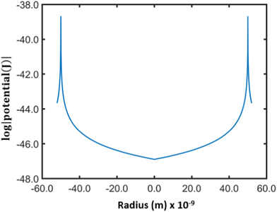
Fig. 2 shows the potential inside a titania nanotube of diameter of 100 nm derived using Lindhard's conventional planar channeling model [eqn (1)].
 | (1) |
It is clear that the potential inside the nanotube is negligible except in the regions near the inner wall. Therefore, the ions entering the pore away from the wall do not experience a potential gradient (electric field) and they can travel through the pores in the same way free particles behave unless they come close to the inner surface.
III. Results and analysis
A. The ion channeling
A molecular-dynamics-based simulation program was developed to study the motion of doubly charged positive He ions inside a titania nanotube. The simulations were performed for a single He ion as well as an ensemble of He ions passing through nanotubes of different geometry and dimensions. The results and conclusions from these studies are discussed below.As the Coulomb potential inside the nanotube pore varies only along the radial direction, the z-component of the linear momentum (pz) of He ions remains unchanged, whereas the other components (px and py) may change. However, the field inside being conservative, the mechanical energy conservation for He ions should hold resembling their motion to that in the case of axial channeling. It is assumed that similar to axial channeling in a single crystal, the transverse energy (Eθ2 + U; E = total energy, U = potential energy, θ = incident angle) of a channeled ion is conserved in a titania nanotube also.
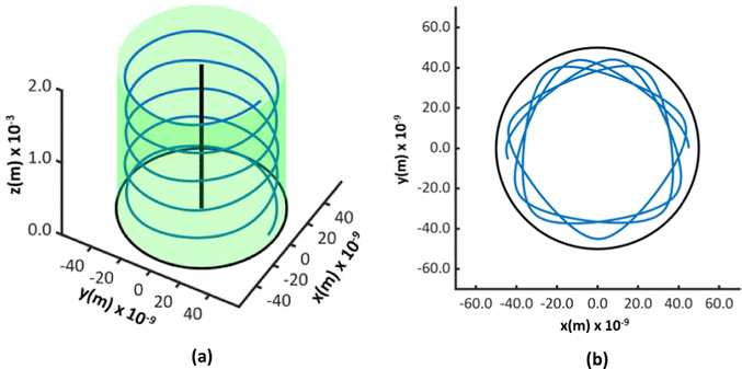
Fig. 3 shows two of the simulated trajectories of a ∼2 MeV He ion projected through the same coordinates on the cross section of a nanotube of a diameter of 100 nm and length 2 mm but at different incident angles. As evident from the figures, the ion is constrained to the pore of the nanotube throughout its trajectory proving that ion channeling occurs in titania nanotubes. The potential inside the pore being substantial only near the walls; the trajectories of ions appear curved near the walls but straight elsewhere.
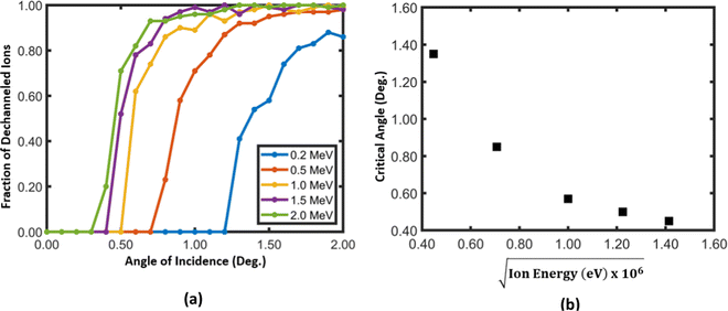
For axial and planar channeling in many single crystals, of which dimensions are in the scale of a few angstroms, the critical angle for 2 MeV He ions is in the scale of approximately 1°.3 In order to determine the channeling critical angles for He ions in titania nanotubes at different energies, ion trajectories were generated for different incident angles and the variation of the fraction of dechanneled ions vs. the incident angle were plotted [Fig. 4]. By taking the full width at half the maximum of each curve, the variation of the critical angle against the square root of energy of ions was also plotted. The figure shows that the critical angle decreases as the energy of ions increases, as given by the Lindhard's relationship for critical angle.1,4 One may expect the critical angles for nanotubes to be greater than those for single crystal materials. The spatial extent of the planar channeling potential is small compared to the radius of curvature of the wall of the nanotube. In close proximity, the potential inside a nanotube is similar to the conventional planar channeling potential. Therefore, the critical angles are similar to those in planar channeling in single crystals, for example, the critical angles in axial and planar channeling for 2.0 MeV He Ions in Si are 0.46° along 〈111〉, 0.55° along 〈110〉 and 0.16° along 〈111〉, 0.17° along 〈110〉 respectively.37
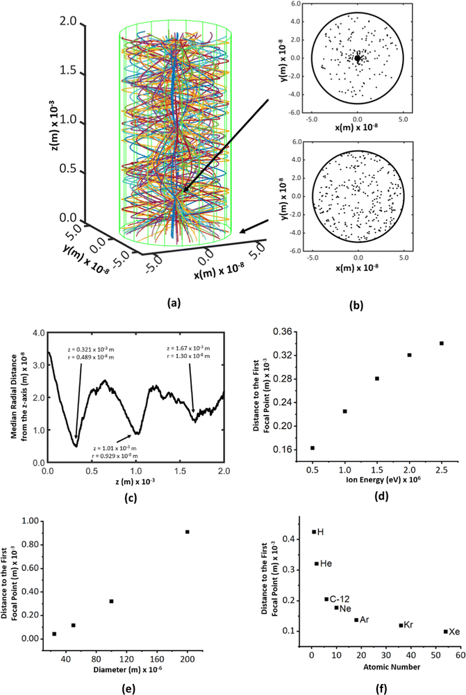
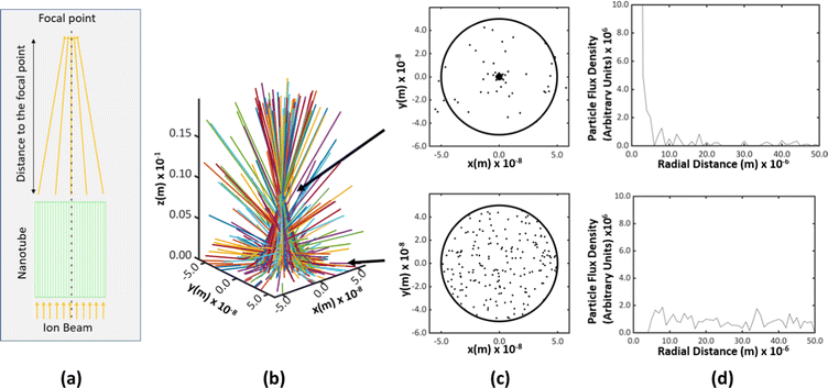
We simulated the trajectories of an ensemble of two hundred He ions randomly distributed over the cross-section of a nanotube and projected into the pore in a direction parallel or inclined to the longitudinal axis of the nanotube. The simulations showed that the ions could indeed channel through titania nanotubes [Fig. 5(a)]. When the ions were projected parallel to the longitudinal axis, the spatial density of trajectories was found to increase sharply at some points [Fig. 5(b)]. Those were identified as the focal points of ions along the channel. The radii of the focal regions were determined by considering the median radial distance of ions from the longitudinal axis of the tube [Fig. 5(c)]. There is a difference between the cross-sectional areas over which He ions are spread, at the entry of a nanotube and at a focal point. In order to quantify the focusing capacity, we took the ratio (Ae − Af)/Ae, where Ae and Af are the cross sectional areas of the ion beam at the point of entry and the focal point respectively. The focusing capacity at the first focal point was calculated to be 99.04%. A higher percentage corresponds to a higher focusing capacity. The ratios for the second and the third focal points are 96.55% and 93.24%, respectively. The work of Wijesundera et al. on planar channeling in single crystal Si showed that the simulated normalized ion flux distribution in Si {100} planar channels for 2 MeV He ion channeling at 0° had a focusing capacity of ∼93% only.38 Titania nanotubes, therefore, have a greater capability for focusing ion beams than single crystals.
The shape of the trajectories is similar to those of typical transverse waves [Fig. 5(a)]. We define the average inter-focal point distance of the first three focal points as the wavelength of channeling ion oscillations. The mean amplitude and the wavelength of the wave shape evolve along the z-direction [Fig. 5(c)]. This is because the wave shape of channeling oscillations is a statistical average of multiple trajectories incident at different locations on the cross-section at z = 0 of the nanotube and the trajectories differ based on the initial position of incidence. This can be understood by individually considering each trajectory shown in Fig. 5(a). When the ions enter the nanotube, they all move in the same direction. When they travel through the nanotube pore, the trajectories get randomized due to the influence of the potential, which determines the lower limit for the size of the focal point.
Fig. 5(d) and (e) show that the focal point can be manipulated with the energy of ions and the diameter of the nanotube. When the energy increases, the velocity and the projected distance to the focal region increase. It shows a variation similar to a logarithmic increment. When the diameter increases, ions should travel a longer distance to pass the focal region showing an exponential increment.
According to the model that we used in this study, the force on an ion due to the potential gradient in the pore of a nanotube, depends on the nuclear charge of the ion (atomic number of the element).1 The ions with a higher nuclear charge experience a stronger repulsive force towards the middle axis of the nanotube and thus, travel a shorter distance before they reach the first focal point [Fig. 5(f)].
The focal points shown in Fig. 5(a) and (c) are located within the pore of the nanotube. However, for practical applications, the focal point should be located outside the ion exit point of the nanotube. In addition, the longer the nanotube, the higher the imperfections in the nanotube geometry and, consequently, the higher the probability of de-channeling. Fig. 6 shows the results for a nanotube having the same diameter, 100 nm, and 1 μm long, creating a focal point outside the nanotube. The ions entering the nanotube pore are subjected to the electric potential inside while traversing 1 μm, which is the length of the nanotube. Once the ions exit the pore, they move along straight lines in space in the same direction as that at the exit point due to the absence of an electric potential.
B. The ion shadow effect
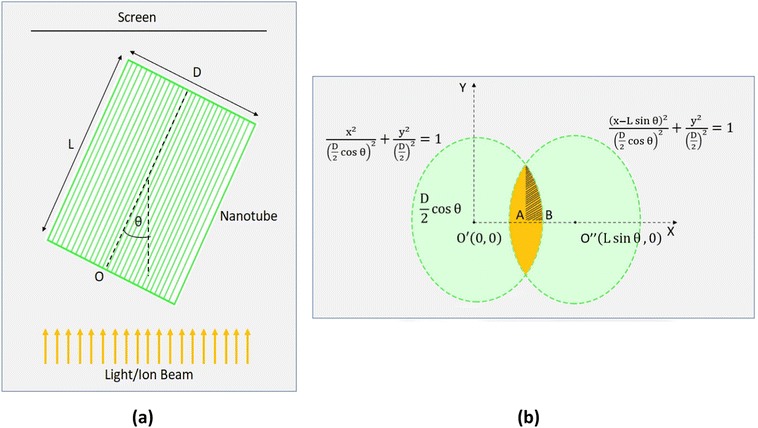
We studied the effect of the incident angle on the channeling effect of 2 MeV He ions through titania nanotubes. The ions were virtually projected into the titania nanotubes inclined at different angles with respect to the direction of ion beams and a quantitative study was made by considering the ion flux transmitted through the nanotubes with different dimensions against the tilted angles. We compared the transmittance of ions through the titania nanotubes to that through some hypothetical nanotubes of similar dimensions with fully ion absorbing walls. We conceptualized these hypothetical nanotubes to observe the results when the ion channeling effect was absent. Such a hypothetical nanotube can be considered as a cylinder with a light absorbing wall in the path of a light beam following geometric optics [Fig. 7(a)]. In the latter case, ions move along straight trajectories inside nanotubes and disappear when they meet the walls. If a screen is placed in front of such nanotubes, the transmitted portion of the flux of ions can be seen in the region as highlighted in Fig. 7(b). A similar shape on the screen is formed when a light beam passes through an opaque hollow cylinder due to the shadows of the walls. Thus, we introduce the name 'the Shadow Effect of ion channeling in nanotubes' for this phenomenon. By comparing the transmittance of ion flux of ion channeling and shadow effect, one can understand how effective the channeling effect is in deflecting ion beams using nanotubes, which we will discuss in a different paper. In addition to the importance of ion beam deflecting, we believe this to be academically interesting for the ion beam community for prospective studies.Fig. 7(b) shows the projections of back and front surfaces of a nanotube on a screen when an ion beam is incident on the nanotube. after tilting the nanotube by an arbitrary angle of θ measured with respect to the middle of axis of the nanotube [Fig. 7(a)] such that the two projected ellipses on the screen stay overlapped. The middle axis of the nanotube is on a plane parallel to the direction of the ion beam. According to projection geometry, when tilted, the projections of the front and back surfaces of the nanotube on the screen become ellipses.
As the two ellipses are equal in dimensions, the area of the overlapped region was calculated using symmetry. Based on the expression for the ion flux through a surface, ϕ = ∮![[F with combining right harpoon above (vector)]](https://www.rsc.org/images/entities/i_char_0046_20d1.gif) ·d
·d![[a with combining right harpoon above (vector)]](https://www.rsc.org/images/entities/i_char_0061_20d1.gif) where
where ![[F with combining right harpoon above (vector)]](https://www.rsc.org/images/entities/i_char_0046_20d1.gif) and
and ![[a with combining right harpoon above (vector)]](https://www.rsc.org/images/entities/i_char_0061_20d1.gif) are the ion flux density and the perpendicular area respectively, the following expression was derived for the transmitted ion flux.
are the ion flux density and the perpendicular area respectively, the following expression was derived for the transmitted ion flux.
 | (2) |
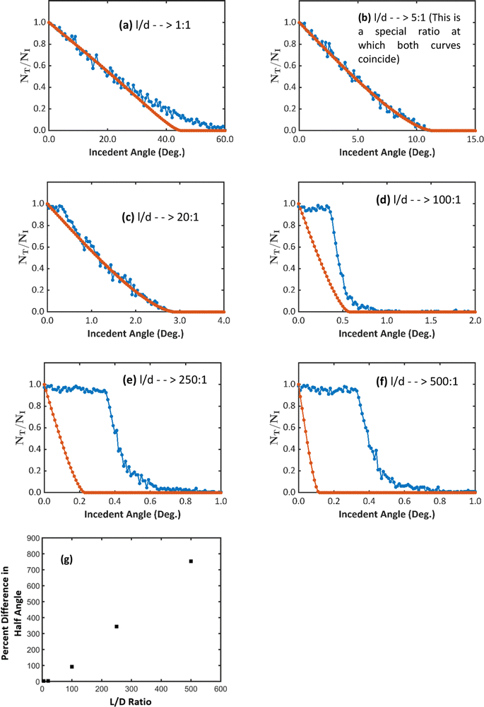
The threshold angle, defined as the angle at which the transmittance reaches zero, decreases as the ratio of length to diameter (the aspect ratio) of nanotubes increases [Fig. 8(a)–(c)]. It depends on the blocking imposed by the walls of nanotubes against the straight trajectories of ions. When the aspect ratio is smaller, the nanotubes have higher threshold angles because they can be tilted more before the wall of the nanotubes block the whole cross-section of the ion beam. When the aspect ratio is greater, the cross-section of the ion beam is blocked completely even when the nanotube is tilted less than 1° causing the threshold incident angles to be smaller.
Three types of deviations of the curves can be seen as the aspect ratios varies; When the length is similar to the diameter of the nanotube, for example, l/d = 1, the curves coincide in the lower range of the angles and gradually become separated at higher angles [Fig. 8(a)]. As the aspect ratio increases, around 20![[thin space (1/6-em)]](https://www.rsc.org/images/entities/char_2009.gif) :
:![[thin space (1/6-em)]](https://www.rsc.org/images/entities/char_2009.gif) 1, the curves coincide [Fig. 8(b)]. But at greater ratios, at around 100
1, the curves coincide [Fig. 8(b)]. But at greater ratios, at around 100![[thin space (1/6-em)]](https://www.rsc.org/images/entities/char_2009.gif) :
:![[thin space (1/6-em)]](https://www.rsc.org/images/entities/char_2009.gif) 1, the curves appear completely shifted from each other [Fig. 8(d)–(f)].
1, the curves appear completely shifted from each other [Fig. 8(d)–(f)].
The difference between the curves emerges due to the fact that under the channeling effect, ions encountering the walls of nanotubes at angles smaller than the critical angle of channeling are diverted back to the void of nanotubes. Consequently, there is always an additional number of ions transmitted due to the channeling effect. In a comparison between the half angles of the transmittance in both effects against the aspect ratio, it can be clearly seen that the percent difference of the half angles shows a constant increase with the aspect ratio of the nanotubes [Fig. 8(g)].
However, the greater the ratio, the more visible the difference between the two effects, even at smaller angles of incidence. As the ratio exceeds the values around 20![[thin space (1/6-em)]](https://www.rsc.org/images/entities/char_2009.gif) :
:![[thin space (1/6-em)]](https://www.rsc.org/images/entities/char_2009.gif) 1, the channeling effect starts manipulating the transmittance. Despite the decrement of the transmittance under the shadow effect, the transmittance under the channeling effect remains nearly constant as long as the angle of incidence does not exceed the channeling critical angle of 0.41°. After that, the channeling effect decreases gradually.
1, the channeling effect starts manipulating the transmittance. Despite the decrement of the transmittance under the shadow effect, the transmittance under the channeling effect remains nearly constant as long as the angle of incidence does not exceed the channeling critical angle of 0.41°. After that, the channeling effect decreases gradually.
IV. Conclusion
Our molecular dynamic simulation results based on the model that we developed using Lindhard's planar channeling potential for a titania nanotube having a diameter of 100 nm and 2 MeV He++ ions, reveal that ion channeling could occur in titania nanotubes. The ion channeling effect in titania nanotubes can efficiently be used for focusing ion beams to the cross-sections in the range of 113 nm2 at focal lengths of 8 mm. The critical angle for ion channeling was found to be less than 1°. The ion channeling effect shows prominence over the shadow effect in the transmittance of an ion beam through a tilted nanotube, when the aspect ratio is above 5![[thin space (1/6-em)]](https://www.rsc.org/images/entities/char_2009.gif) :
:![[thin space (1/6-em)]](https://www.rsc.org/images/entities/char_2009.gif) 1. Since critical angles for ion channeling are less than 1°, from a technological standpoint, it is challenging to make parallel nanotube arrays for ion channeling to occur. Nevertheless, anodic oxidation that yields highly ordered nanotube arrays is promising for the precise fabrication of ion beam focusing assemblies. A potential issue with the titania nanotubes is that when nanotubes are bombarded with high energy ions, the radiation damage can drop the productivity of the channeling effect. A post bombardment annealing could be a solution. If such complications are properly addressed, ion channeling in titania nanotubes would find applications in various fields, including electronic device fabrication using ultra-narrow ion beams and magnet-free ion beam deflectors.
1. Since critical angles for ion channeling are less than 1°, from a technological standpoint, it is challenging to make parallel nanotube arrays for ion channeling to occur. Nevertheless, anodic oxidation that yields highly ordered nanotube arrays is promising for the precise fabrication of ion beam focusing assemblies. A potential issue with the titania nanotubes is that when nanotubes are bombarded with high energy ions, the radiation damage can drop the productivity of the channeling effect. A post bombardment annealing could be a solution. If such complications are properly addressed, ion channeling in titania nanotubes would find applications in various fields, including electronic device fabrication using ultra-narrow ion beams and magnet-free ion beam deflectors.
Conflicts of interest
There are no conflicts to declare.References
- J. Lindhard, Influence of crystal lattice on motion of energetic charged particles, Mathematisk-fysiske meddelelser, 1965, vol. 34 Search PubMed.
- S. T. Picraux, Channeling in semiconductors and its application to the study of ion implantation, PhD dissertation, Caltech, 1969 Search PubMed.
- A. Vantomme, 50 years of ion channeling in materials science, Nucl. Instrum. Methods Phys. Res., Sect. B, 2015, 371, 12–26 CrossRef.
- L. C. Feldman, J. W. Mayer and S. T. Picraux, Materials analysis by ion channeling submicron crystallography, Academic Press, 1984 Search PubMed.
- W. K. Chu, J. W. Mayer and M. A. Nicolet, Backscattering Spectrometry, Academic Press, 1978 Search PubMed.
- D. N. Wijesundera, Ion-beam channeling in non-centrosymmetric crystals, PhD dissertation, Uni. of Houston, 2010 Search PubMed.
- D. N. Wijesundera, Q. Chen, K. B. Ma, X. Wang, B. Tilakaratne and W. K. Chu, Planar channeling in wurtzite structured ZnO (0 0 0 1): anisotropic effects due to the non-centrosymmetric structure, Nucl. Instrum. Methods Phys. Res., Sect. B, 2012, 281, 77–81 CrossRef CAS.
- J. F. Ziegler, Ion implantation science and technology, Ion Implantation Technology Co., 1996 Search PubMed.
- V. V. Klimov and V. S. Letokhov, Hard X-radiation emitted by a charged particle moving in a carbon nanotube, Phys. Lett. A, 1996, 222(6), 424–428 CrossRef CAS.
- L. A. Gevorgyan, K. A. Ispiryan and R. K. Ispiryan, Channeling in single-wall nanotubes: possible applications, J. Exp. Theor. Phys. Lett., 1997, 66, 322–326 CrossRef.
- N. K. Zhevago and V. I. Glebov, Channeling of fast charged and neutral particles in nanotubes, Phys. Lett. A, 1998, 250(4–6), 360–368 CrossRef CAS.
- G. V. Dedkov, Fullerene nanotubes can be used when transporting gamma-quanta, neutrons, ion beams and radiation from relativistic particles, Nucl. Instrum. Methods Phys. Res., Sect. B, 1998, 143(4), 584–590 CrossRef CAS.
- G. V. Dedkov and B. S. Karamurzov, Fullerene nanotubes as transporting and focusing elements of nanoscale beam technology, Surf. Coat. Technol., 2000, 128–129, 51–58 CrossRef CAS.
- S. Bellucci, V. M. Biryukov, Yu. A. Chesnokov, V. Guidi and W. Scandale, Channeling of high energy beams in nanotubes, Nucl. Instrum. Methods Phys. Res., Sect. B, 2003, 202, 236–241 CrossRef CAS.
- A. V. Krasheninnikov and K. Nordlund, Channeling of heavy ions through multi-walled carbon nanotubes Nucl. Instrum, Methods Phys. Res. B, 2005, 228(1–4), 21–25 CrossRef CAS.
- M. Meyyappan, L. Delzeit, A. Cassell and D. Hash, Carbon nanotube growth by PECVD: a review, Plasma Sources Sci. Technol., 2003, 12, 205–216 CrossRef CAS.
- N. Saifuddin, A. Z. Raziah and A. R. Junizah, Carbon nanotubes: a review on structure and their interaction with proteins, J. Chem., 2012, 2013, 676815 Search PubMed.
- M. Paulose, et al., Anodic growth of highly ordered TiO2 nanotube arrays to 134 μm in length, J. Phys. Chem. B, 2006, 110(33), 16179–16184 CrossRef CAS PubMed.
- X. Artru, S. P. Fomin, N. F. Shul’ga, K. A. Ispirian and N. K. Zhevago, Carbon nanotubes and fullerites in high-energy and X-ray physics, Phys. Rep., 2005, 412(2–3), 89–189 CrossRef CAS.
- S. Bellucci, Nanotubes for particle channeling, radiation and electron sources, Nucl. Instrum. Methods Phys. Res., Sect. B, 2005, 234(1–2), 57–77 CrossRef CAS.
- Z. L. Miskovic, Ion channeling through carbon nanotubes, Radiat. Eff. Defects Solids, 2007, 162(3–4), 185–205 CrossRef CAS.
- D. Borka, S. Petrovic and N. Neskovic, Channeling of protons through carbon nanotubes, J. Phys.: Conf. Ser., 2008, 133, 012015 CrossRef.
- B. M. Rao, A. Torabi and O. K. Varghese, Anodically grown functional oxide nanotubes and applications, MRS Commun., 2016, 6, 375–396 CrossRef CAS.
- X. Chen and S. S. Mao, Titanium dioxide nanomaterials: synthesis, properties, modifications, and applications, Chem. Rev., 2007, 107(7), 2891–2959 CrossRef CAS PubMed.
- O. K. Varghese, K. Stancato, M. Paulose and R. Neupane, Titania nanotubes, in 21st century nanoscience – a handbook, 2020, vol. 4, p. 17 Search PubMed.
- G. K. Mor, O. K. Varghese, M. Paulose, K. Shankar and C. A. Grimes, A review on highly ordered, vertically oriented TiO2 nanotube arrays: fabrication, material properties, and solar energy applications, Sol. Energy Mater. Sol. Cells, 2006, 90(14), 2011–2075 CrossRef CAS.
- M. Paulose, H. E. Prakasam and O. K. Varghese, et al., TiO2 nanotube arrays of 1000 μm length by anodization of titanium foil: phenol red diffusion, J. Phys. Chem. C, 2007, 111(41), 14992–14997 CrossRef CAS.
- L. P. Zheng, C. B. Wang, Z. J. Xu, Z. Y. Zhu, D. Z. Zhu and H. H. Xia, Channeling of low energy light and heavy ions in single-wall nanotubes, Nucl. Instrum. Methods Phys. Res., Sect. B, 2016, 260, 513–516 CrossRef.
- X. Cauchy and S. Roorda, Nearly equidistant single swift heavy ion impact sites through nanoporous alumina masks, AIP Conf. Proc., 2013, 1525, 375 CrossRef CAS.
- L. C. Feldman and J. W. Mayer, Fundamentals of Surface and Thin Film Analysis, Elsevier Science Publishing Co., Inc., New York, 1986 Search PubMed.
- J. R. Tesmer, M. Nastasi, J. C. Barbour, C. J. Maggiore and J. W. Mayer, Handbook of Modern Ion Beam Materials Analysis, Materials Research Society, Pittsburgh, PA, 1995 Search PubMed.
- L. Verlet, Computer experiments on classical fluids. I. thermodynamical properties of Lennard-Jones molecules, Phys. Rev., 1967, 159(1), 98–103 CrossRef CAS.
- W. H. Press, et al., Numerical recipes in C: the art of scientific computing, Cambridge University Press, 2nd edn, 1992 Search PubMed.
- O. K. Vargese and D. Gong, et al., Crystallization and high-temperature structural stability of titanium oxide nanotube arrays, J. Mater. Res., 2003, 18(1), 156–165 CrossRef.
- O. K. Varghese, M. Paulose and C. A. Grimes, Long vertically aligned titania nanotubes on transparent conducting oxide for highly efficient solar cells, Nat. Nanotechnol., 2009, 4, 592–597 CrossRef CAS PubMed.
- M. Gardon and J. M. Guilemany, Milestones in functional titanium dioxide thermal spray coatings: a review, J. Therm. Spray Technol., 2014, 23(4), 577 CrossRef CAS.
- S. T. Picraux, J. A. Davies, L. Eriksson, N. G. E. Johansson and J. W. Mayer, Channeling studies in diamond-type lattices, Phys. Rev., 1969, 180(3), 873–882 CrossRef CAS.
- D. N. Wijesundera, K. B. Ma, X. Wang, B. P. Tilakaratne, L. Shao and W. K. Chu, The role of flux-focusing in the origin of shoulders in ion channeling angular scans, Phys. Lett. A, 2012, 376(22), 1763–1766 CrossRef CAS.
Footnote |
| † Electronic supplementary information (ESI) available. See DOI: https://doi.org/10.1039/d2ma00573e |
| This journal is © The Royal Society of Chemistry 2023 |

