Covalent organic framework assisted interlocked graphene oxide based thin-film composite membrane for effective water remediation†
Received
14th July 2022
, Accepted 21st November 2022
First published on 2nd December 2022
Abstract
2D materials like graphene oxide (GO) based free-standing membranes, although have shown excellent salt rejection at short time scales, suffer from structural stability and swelling on prolonged use. Hence, in this study, a unique approach of crosslinking GO sheets with a dense ‘covalent organic framework’ (to yield GO@COF) was designed to selectively reject ions and dyes. The swelling of the GO@COF membrane was also restricted due to the crosslinking of GO nanosheets. The GO@COF membrane was supported on a porous crystalline support (here polyvinylidene difluoride, PVDF) designed by etching out the amorphous phase (here polymethyl methacrylate, PMMA) from a demixed crystalline/amorphous pair. This arrangement showed good water flux, fouling resistance, and >90% dye rejection. In order to enhance the rejection further and to improve the chlorine tolerance of the membrane, a COF embedded polyamide (PA) thin film composite membrane was designed in situ on this highly stable, non-swellable GO@COF membrane. This modified membrane showed excellent salt (>94% and >98% for monovalent and divalent ions, respectively) and dye (>99.90% for both cationic and anionic dyes) rejection and in addition, demonstrated excellent resistance to fouling (>93%). Moreover, this sandwich structure revealed outstanding chlorine tolerance performance, thereby addressing most major challenges faced by either 2D material based or thin film composite membranes.
Water impact
A novel uniform dense COF embedded PA layer was deposited on a highly stable GO@COF nanohybrid membrane to reject ions and dye molecules selectively. The GO@COF nanohybrid membrane was stitched to a supported hierarchical porous PVDF membrane. This thin film composite membrane showed outstanding dye and salt rejection in addition to the outstanding fouling resistance. Therefore this membrane proved to be a productive strategy to remediate water for domestic as well as industrial application.
|
1. Introduction
In recent years, the freshwater crisis and energy shortage have been major problems that continue to increase worldwide. The world's population is growing at more than 7 billion, and as a result, one in seven people on the globe does not have access to safe drinking water. Between 2000 and 2050, the planet's demand for clean water is expected to enhance by 55%, where agriculture, industrial and municipal sectors account for 70% of universal clean water use.1 Although many steps have been taken towards improving the quality and availability of freshwater, factors such as burgeoning population, uncontrolled and rapid urbanization, agricultural practices, and climate disruption have exponentially increased the demand for clean and fresh water. So, in this context, a sustainable and cost-effective approach to the supply of clean water has been one of the most significant challenges in recent years. Membrane technology has gained vast and increasing popularity in water remediation applications due to its easy scale-up and cost-effective features.2 Hence, the improvement of feasible membrane technology for water purification and desalination is necessary because of its excellent separation performance, low energy consumption, moderate process conditions, eco-friendliness, and small footprint.3–5
Membranes with efficient pore arrangement and symmetrical pore size are important for highly selective separation techniques like water desalination and purification.6–12 Graphene oxide (GO), a modified form of graphene with functional groups such as hydroxyl, carboxyl, epoxy, and carbonyl, has offered numerous opportunities because of its facile fabrication.13–18 GO nanosheets are layered structures that operate as nanochannels for selective separation of water organic molecules.15,19–26 Due to tortuous pathways, GO membranes often show low permeation flux.27–29 One suitable approach to enhance the flux is to widen the interlayer distance by adding intermittent materials, such as zeolite imidazole frameworks,30 metal–organic frameworks,31,32 TiO2,33,34 carbon nanotubes,35 and other functional materials.36,37 This technique has been tested to attain superior flux than primitive GO membranes, although, in most experiments, selectivity is largely compromised. Reduced GO can decrease the quantity of oxygen-containing groups on the surface of the GO to enhance the stability but will lead to a reduced distance between two consecutive layers, which finally offers lower flux.38,39
Covalent organic frameworks (COFs) are a new class of two-dimensional (2D) materials. The highly porous structure, well-organized pores, and high thermal stability of these materials hold great promise for effective membrane desalination.40,41 Moreover, COFs containing pure organic constituents are highly compatible with polymer matrices.42 For nanofiltration applications, it is important to access the pores of COFs which requires efficient exfoliation of the COF,43–49 but the process of exfoliation is persistently difficult. Additionally, for water filtration, several major requirements such as stability in an aqueous environment and under harsh conditions and sufficient pore size are significant factors. Triazine-based COFs can also be exfoliated into nanosheets, including amine groups, which play a vital role in chemical bonding. These points make COFs a promising candidate for mixed nanosheet membranes, particularly by conjugating with GO nanosheets. However, nanoporous COFs can provide more accessible monomers and aggregation methods owing to their structural varieties as compared to impenetrable GO. Even though COF and GO mixed nanosheet laminates offer a promising combination, they have not received much attention. Zhong et al.50 revealed the significance of COF pores by physically combining them with GO nanosheets, and the fabricated membrane was utilized for separation of gas under dry conditions. In aqueous solution, the stability of GO-based membranes remains a big challenge for the separation of liquid due to their degradation and delamination. Crosslinking porous COF nanosheets with nonporous GO forming stable chemical bonding can contribute novel structural blocks for synthesizing 2D based membranes with better rejection performances.
Though PA-based thin film composite (TFC) membranes are well established in the literature, the problems associated with these membranes are poor mechanical stability, being prone to fouling, and disintegration under exposure to a chlorine environment.51 Different carbon-based inorganic nanomaterials52–55 with TFCs have been reported. Also, three-dimensional network-like metal–organic frameworks have been incorporated into the PA layer to address some of these challenges.56–58 The agglomeration of nanoparticles above a specific concentration leads to the deterioration of the efficacy of the membrane. Therefore, incorporating COFs into the PA layer is a robust strategy to enhance the stability and effective desalination in the TFC membrane.59
In this work, we have prepared highly oxidized GO from graphene and fabricated a freestanding GO membrane using a vacuum-assisted filtration technique. In addition, COFs have been synthesized from 1,3,5-triformylphloroglucinol and melamine using a solvothermal method. The stability and permeability of the freestanding GO membrane are enhanced by incorporating COFs. The COFs crosslinked the GO layers chemically which restricted the swelling of the GO membrane. The obtained COF crosslinked GO freestanding membrane was stitched onto a porous PVDF support designed from demixed blends (PVDF and PMMA) followed by etching PMMA from token membrane samples.60 This composite membrane showed excellent water permeability, dye rejection performance, salt rejection, and antifouling properties. A thin layer of optimum COF embedded PA has been fabricated by an interfacial polymerization process onto the composite membrane's surface to enhance its efficacy. Thus, our study offers an effective strategy to improve desalination without compromising other key requirements.
2. Experimental section
2.1. Materials
PVDF and PMMA were bought from Arkema and Gujpol, respectively. Graphite powder was supplied by Superior Company, India. Melamine (99%), piperazine, trimesoyl chloride (TMSCl) (98%), phloroglucinol (99%), acrylic acid (99%), hexamethylenetetramine (99%), 1-ethyl-3-(3-dimethylaminopropyl) carbodiimide (99.99%) (EDC), and N-hydroxysuccinimide (99.99) (NHS) were procured from Sigma Aldrich, and sodium chloride (99.90%), sodium sulfate, hydrogen peroxide, magnesium nitrate (99%), potassium permanganate, hexane, dimethyl acetamide, ethanol, dimethyl sulphoxide, acetone, sulfuric acid, acetic acid, phosphoric acid, and trifluoroacetic acid were collected from local vendors.
2.2. Synthesis of GO
As reported in the literature, GO was synthesized by the modified Hummer's method in a highly acidic medium.61 In brief, 1 g graphite powder was added to a mixture of H3PO4 and H2SO4 (62 ml, 7![[thin space (1/6-em)]](https://www.rsc.org/images/entities/char_2009.gif) :55 by volume). The mixture was kept under magnetic stirring conditions at 0–4 °C for an hour followed by the addition of KMnO4 (6 g). To achieve complete oxidation it was kept stirring for three days at room temperature. The reaction was arrested, and the addition of H2O2 dropwise neutralized the excessive KMnO4. The unreacted graphite was washed out thoroughly with 1N HCl and DI water successively. The GO was obtained by centrifugation at 8000 rpm, and it was kept drying under a vacuum at room temperature.
:55 by volume). The mixture was kept under magnetic stirring conditions at 0–4 °C for an hour followed by the addition of KMnO4 (6 g). To achieve complete oxidation it was kept stirring for three days at room temperature. The reaction was arrested, and the addition of H2O2 dropwise neutralized the excessive KMnO4. The unreacted graphite was washed out thoroughly with 1N HCl and DI water successively. The GO was obtained by centrifugation at 8000 rpm, and it was kept drying under a vacuum at room temperature.
2.3. Synthesis of 1,3,5-triformylphloroglucinol (TFP)
TFP was synthesized by using previously reported procedures.62 In brief, 3 g of dried phloroglucinol, 7.4 g HMT (hexamethylenetetramine), and trifluoroacetic acid (45 mL) were mixed in a round-bottom flask. The addition of trifluoroacetic acid was carried out carefully in an ice bath. The temperature of the mixture was slowly increased to room temperature (RT). The reaction mixture was further allowed to reflux at 100 °C under a N2 atmosphere for 2.5 h. Next, 3M hydrochloric acid was added dropwise and was further refluxed for another 1 h. Finally, the solution was allowed to settle down to RT and filtered through a celite bed. The obtained filtrate was worked up with DCM (5 times) and dried over anhydrous Na2SO4. The organic solution was then concentrated to yield a yellow-colored solid. The crude product was recrystallized in hot ethanol, and finally, the desired product was obtained. The 1H NMR spectrum of the product is given in Fig. S1.†
2.4. Synthesis of the phloroglucinol melamine covalent organic framework (COF)
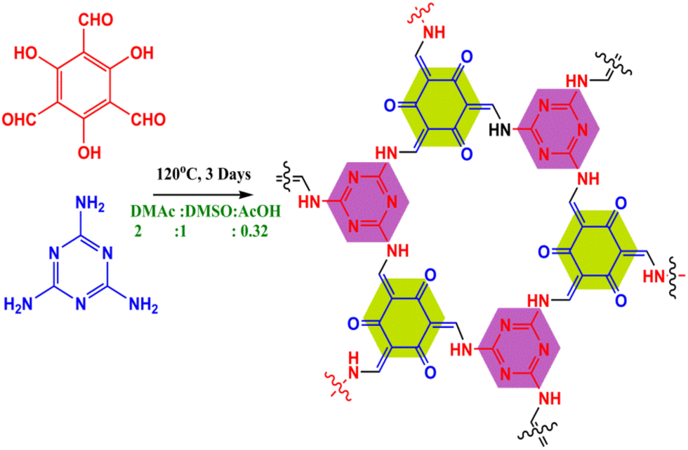
The COF was synthesized via salt-mediated Schiff base condensation using a solvothermal process as reported in the literature.63 In brief, 1,3,5-triformylphloroglucinol (TFP) (190 mg, 0.9 mmol) and melamine (MM) (114 mg, 0.9 mmol) were added in the presence of N,N-dimethylacetamide (DMAc) and dimethyl sulfoxide (DMSO) solvent combination (2:1 mL) with 0.3 mL of 6 M aqueous acetic acid. The reaction mixture was ultrasonicated for 20 min for homogeneous dispersion and degassed through three successive freeze–pump–thaw cycles. Then, under vacuum conditions, the tube was sealed and heated at 120 °C in an isothermal oven for three days. Finally, the resultant material was filtered out and washed extensively with DMAc solvent to remove the impurities. The collected pure yellowish material was solvent exchanged with DMAc and H2O and washed with an excess of acetone. Finally, the powder compound was dried at 120 °C under vacuum for 8 h to obtain the synthesized COF (80% yield). The reaction scheme is shown in Fig. 1.
 |
| | Fig. 1 Scheme showing the synthesis of the COF. | |
2.5. Synthesis of the GO@COF membrane
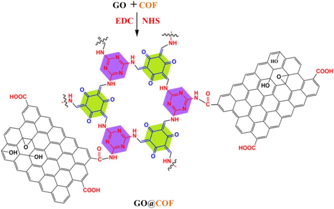
GO (30 mg) was dispersed in water for 3 h. The carboxylic acid groups of GO were activated by the addition of EDC (100 mg) and NHS (80 mg) simultaneously into the GO colloidal suspension (1 mg ml−1, pH ∼7) which was stirred for 6 h at RT. The activated GO was filtered, washed with DI water and dried at 50 °C for 12 h. On the other hand, the COF (0.1 mg ml−1) was sonicated for 6 h for proper dispersion in a water medium. Then the COF dispersion at different ratios was added to the dispersion of activated GO, and the reaction mixture was stirred at RT for 24 h. Finally, the reaction mixture was vacuum filtered for membrane synthesis. Thus the obtained GO@COF membrane was kept in DI water to check the stability of the membrane (see Fig. S6†). The reaction between the COFs and GO is represented in Fig. 2.
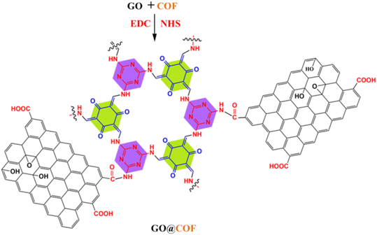 |
| | Fig. 2 Scheme showing the synthesis of the GO@COF membrane. | |
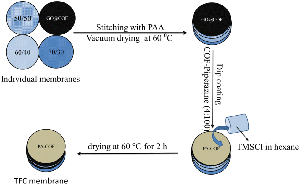
2.6. Fabrication of the thin-film composite membrane
The GO@COF membrane was stitched to the surface of a pretreated hierarchical porous PVDF membrane,60 hence the membrane is called the GO@COF modified membrane hereafter. The details of pretreatment of the PVDF membrane are mentioned in the ESI† (Fig. S2). The thin-film composite membrane was prepared by the in situ interfacial polymerization technique. For this, piperazine (2 g L−1) was dissolved in water. Then the COF (varying percentage with respect to the amount of piperazine) was added to the piperazine solution and bath sonicated for 2 h. On the other hand, trimesoyl chloride (2 g L−1) was dissolved in n-hexane. The COF embedded TFC was formed by drop-casting the aqueous solution of amine onto the membrane surface followed by the addition of the organic solution of trimesoyl chloride and the casting procedure was repeated 5 times to obtain a denser thin film. Then it was kept for curing at 60 °C for 2 h. The scheme showing the fabrication of the TFC membrane is presented in Fig. 3.
 |
| | Fig. 3 Scheme showing the fabrication of the TFC membrane. | |
3. Characterization of the membranes
The GO and COFs were analyzed using FTIR (Perkin Elmer Frontier). The stability of the COFs was determined using a thermo gravimetric analyzer (TA Q 500). The GO and COFs' structures were identified using XRD (Bruker D8 Advance). The morphology of the membranes was characterized by SEM equipped with an EDX detector. A contact angle goniometer was used to determine the hydrophilicity of all the membranes.
4. Permeation and antifouling test
4.1. Pure water flux
The flux of all the composite membranes was evaluated in a hand-made lab-scale cross flow setup. Each membrane having a 30 mm diameter was compacted initially at a pressure of 0.21 MPa for 30 min. Then the pressure was varied from 0.21 MPa to 0.51 MPa. Subsequently, the data were recorded three times at 0.21 MPa and 0.413 MPa to check the reproducibility.
4.2. Dye rejection performance
100 ppm dye solutions were used separately as model dyes to understand the sieving performance. In a cross-flow setup, the permeate was collected at 0.413 MPa, and the concentration of dye in the permeate was determined with the help of UV vis spectrometry. The sieving performance was calculated using the following formula:
| %rejection = [1 − (Cpd/Cfd)] × 100 |
Cpd = permeate dye concentration in ppm, and Cfd = feed dye concentration in ppm.
4.3. Desalination performance
A typical in-built FO setup was utilized to study the salt rejection performance of the composite membranes. In this study, 2000 ppm of both monovalent and divalent salts, i.e., NaCl and Mg (NO3)2, were taken separately as draw solutions and 20 ppm of distilled water as a feed solution. The feed and draw solution concentrations were monitored using a TDS meter at a specific time. The rejection efficiency was calculated from the following formula:
| %rejection = [1 − ((Cfd − Cfi)/Cid)] × 100 |
where Cfd = final concentration of feed in ppm, Cfi = initial concentration of feed in ppm and Cid = initial concentration of draw in ppm.
4.4. Fouling test
1 g L−1 aqueous solution of BSA was utilized to check the tendency of the membrane towards fouling attack. The test was done under dynamic conditions. At first pure water flux (Jw) was recorded, followed by BSA flux (Jb). The membrane was backflushed with 1× PBS solution, and pure water flux was again recorded (Jp). The antifouling characteristics of the membranes were reported in terms of the FRR (flux recovery ratio), IFR (irreversible flux decline ratio), and RFR (relative fouled flux ratio) and hence calculated from the given formulas:
5. Stability test
5.1. Long term stability of the membrane
The TFC membrane was run for a long time in a cross-flow setup. The dye water flux and rejection performance were recorded at regular intervals at 0.41 MPa pressure. The stability of the membrane was evaluated based on the consistency of the flux and rejection values.
5.2. Chlorine tolerability of the membrane
The chlorine tolerance performance of the TFC membranes was evaluated by dipping the membranes in 8000 ppm of sodium hypochlorite solution for an hour. After that, the salt rejection efficiency was recorded as earlier in FO mode. The chlorine stability of the membrane was measured by deviation in salt rejection before and after the chlorine exposure.
6. Results
6.1. Characterization of GO
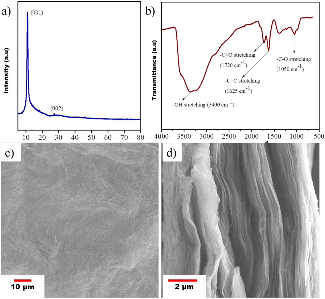
The structural properties of synthesized GO were analyzed by powder XRD, where Cu Kα was used as a source. The GO was scanned from 5° to 80° at a step size of 0.049°. The formation of GO from graphite flakes was assessed by the appearance of a peak at 10.98°. The peak obtained at 27.20° with minimal intensity assured that no unreacted graphite adhered to the GO (refer to Fig. 4a). The formation of GO from graphite flakes was further assessed by FTIR, as shown in Fig. 4b. The appearance of peaks at 1720 cm−1 and 1050 cm−1 corresponds to the characteristic peaks of carbonyl stretching and epoxy C–O stretching, respectively. The intense broad peak at 3400 cm−1 also signifies the stretching of hydroxyl groups present in GO. A scanning electron microscope was used to characterize the morphology of the GO membrane. Fig. 4c shows the slightly smooth surface of the GO membrane and the lamella structure of GO is observed from the cross-sectional morphology (Fig. 4d).
 |
| | Fig. 4 (a) XRD pattern, (b) FTIR spectrum, (c) surface SEM image and (d) cross-sectional SEM image of the free standing GO membrane. | |
6.2. Characterization of the COF
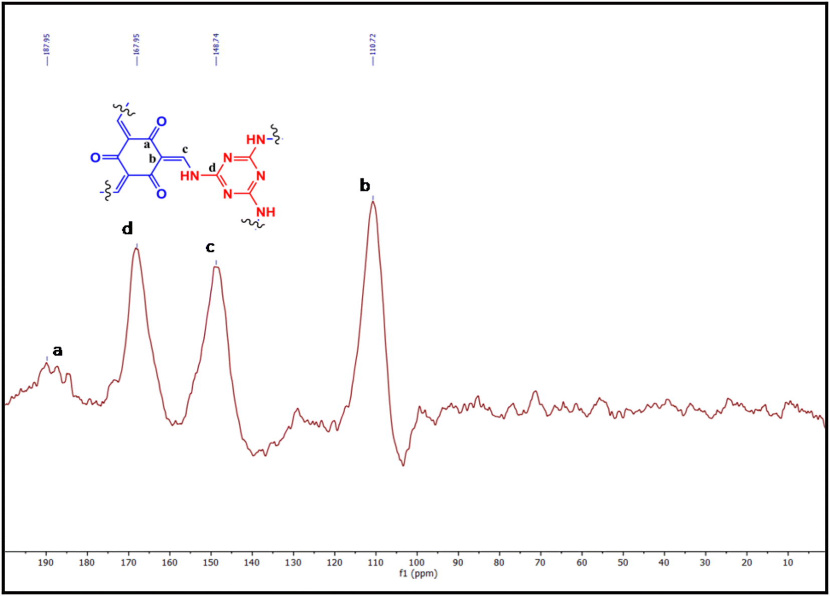
The atomic-level orientations of the COF backbone have been confirmed from solid-state 13C NMR spectroscopy. The characteristic signal at 187.9 ppm indicating the carbon atom from the C![[double bond, length as m-dash]](https://www.rsc.org/images/entities/char_e001.gif) O functionality originated due to the keto–enol tautomerism, and the peak at 167.9 ppm corresponded to aromatic carbons of the triazine core. The rest of the peaks of the COF also displayed the sp2 carbon positions at 148 and 110 ppm, respectively (Fig. 5).
O functionality originated due to the keto–enol tautomerism, and the peak at 167.9 ppm corresponded to aromatic carbons of the triazine core. The rest of the peaks of the COF also displayed the sp2 carbon positions at 148 and 110 ppm, respectively (Fig. 5).
 |
| | Fig. 5 Solid-state 13C NMR spectrogram of the COF (a–d show the corresponding peak position of the labelled carbons as depicted the provided chemical structure). | |
The FT-IR spectra of 1,3,5-triformylphloroglucinol, melamine, and the COF are provided in Fig. 6a. The absorption bands centered at 3462, 3414, and 3330 cm−1 can be ascribed to the –NH2 groups present in melamine. In addition to that, one intense peak was found at 1640 cm−1 due to the (–CN) stretching. But in the case of 1,3,5-triformylphloroglucinol, the absorption peaks at 2965 cm−1 and 1638 cm−1 indicate the (–CHO) stretching and (–CO) stretching, respectively. The successful inclusion of β-ketoenamine links in the COF is shown by the appearance of strong peaks at 1523 cm−1 (–CC), 1615 cm−1 (–CO), and 3340 cm−1 (–NH) in the FTIR spectra. The structure of the synthesized COF was analyzed by XRD. The XRD pattern shows two intense peaks at 2θ = 13.68° and 27.52° corresponding to the (001) and (002) planes, respectively. From the (002) peak, it may be concluded that the interlayer distance or π–π stacking distance between two COF layers is near about 3.3 A°. The morphology of the COF material was observed by SEM, which revealed that the COF crystallites show a fibrillar morphology, as shown in Fig. 6c. In Fig. 6d, the nitrogen adsorption–desorption analysis of the COF material provided critical information about its surface area and overall porosity. The result shows that the synthesized COF possesses a surface area of 387.59 m2 g−1 and an overall pore volume of 91.40%. The pore size of the COF was determined by the BJH method and was found to be less than 2 nm (Fig. 6e). The outstanding thermal stability of the COF was manifested by the thermogravimetric analysis data shown in Fig. 6f. From the TGA curves, it is observed that the two main precursors (melamine and 1,3,5 triformylphloroglucinol), which were utilized to synthesize the COF, have very low thermal stability (maximum 250 °C). However, the final structure (COF) showed excellent thermal stability, as evident from the TGA thermogram.
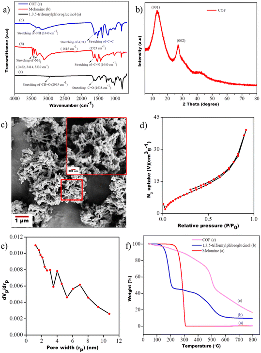 |
| | Fig. 6 (a) FTIR spectra of the COF and its precursors, (b) XRD pattern of the COF, (c) SEM micrograph of the COF material (inset showing a higher magnification image), (d) Brunauer–Emmett–teller (BET) surface adsorption of the COF, (e) pore size distribution of the COF using the Barrett–Joyner–Halenda (BJH) method and (f) TGA curves of the COF and its precursors. | |
6.3. Characterization of the GO@COF membrane
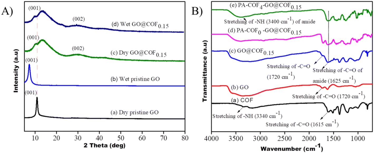
Four different types of GO@COF membranes were prepared based on the composition of the COF & GO. The amounts of COFs which were added to cross-link GO are 1.5 mg (COF/GO = 0.05), 3 mg (COF/GO = 0.10), 4.5 mg (COF/GO = 0.15), and 6 mg (COF/GO = 0.20), respectively. Hence these membranes are named GO@COF0.05, GO@COF0.10, GO@COF0.15, and GO@COF0.20, respectively. The morphology of all the cross-linked membranes was analyzed by SEM (see Fig. S3† and 7). The surface of cross-linked GO becomes rougher with the concentration of COF in GO, leading to a more hydrophilic surface as assisted by the decreased value of contact angle (see Table S1 in the ESI†). Moreover, the COF agglomerates on GO beyond a certain concentration. Therefore the GO@COF0.20 becomes mechanically unstable. Hence the GO@COF0.15 membrane is considered as the optimized membrane for further modification. The elemental mapping on GO and all the GO@COF membranes is shown in Fig. S4.† The structure of all the membranes was evaluated by the XRD data (see Fig. S5†). The addition of the COF onto GO broadens the (001) peak of GO by slightly shifting the position of the peak towards a lower angle. Therefore the addition of the COF increases the interplanar distance of GO only slightly, manifesting the incorporation of the COF only between the edges of two GO layers, not in the interlayer region, as shown in Fig. 7. Moreover the (002) peak becomes more prominent, which confirms the reduction of GO during the synthesis of the GO@COF. To ensure the stability of the GO@COF0.15 membrane compared to the pristine GO membrane, they were immersed in water for 24 h, and the XRD data of both membranes under wet conditions were analyzed. From Fig. 8(a), it is seen that the pristine GO swells more (the interlayer distance increases from 8.04 A° to 12.50 A°) compared to the GO@COF0.15 membrane (the interlayer distance changes from 8.57 A° to 8.80 A°). Therefore cross-linking between the COF &GO restricts the swelling of GO as evident from the XRD studies. To assess further the stability of the GO@COF0.15 membrane, it was kept immersed in water for more than 30 days. It was observed that the membrane is highly stable even on applying stress on it underwater, as shown in the figure (see Fig. S6†). The chemical cross-linking between the COF and GO was evaluated by FTIR. In Fig. 8(B), the reduction in the intensity of carboxyl groups (1720 cm−1) of GO and the complete disappearance of the amine group (3340 cm−1) strongly suggest the cross-linking between the COF and GO. Moreover, the appearance of a broad peak at 1625 cm−1 of –CO stretching associated with –CC stretching of GO strongly confirms the cross-linking between the GO and COF.
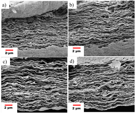 |
| | Fig. 7 Micrograph showing the cross-sectional morphology of the GO@COF membrane at different compositions: (a) GO@COF0.05, (b) GO@COF0.10, (c) GO@COF0.15, and (d) GO@COF0.20, respectively. | |
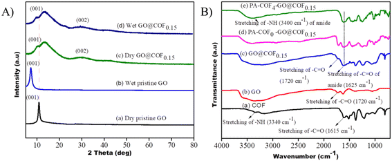 |
| | Fig. 8 (A) XRD patterns of the pristine GO and GO@COF0.15 membrane under dry and wet conditions. (B) FTIR spectra of the GO@COF0.15 membrane and TFC membranes. | |
6.4. Characterization of the TFC membrane
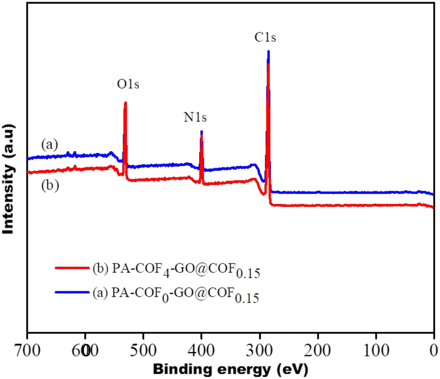
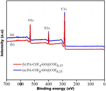
Six different TFC membranes were prepared by varying the concentration of the COF in piperazine to yield the PA-COF-GO@COF0.15 membrane. Hence these are referred to as PA-COF0-GO@COF0.15, PA-COF1-GO@COF0.15, PA-COF2-GO@COF0.15, PA-COF3-GO@COF0.15, PA-COF4-GO@COF0.15, and PA-COF5-GO@COF0.15 modified membranes, respectively (where 0, 1, 2, 3, 4, and 5 refers to the % of COF in the piperazine solution). As an example, the deposition of PA layers on the surface of the GO@COF0.15 modified membrane was characterized by FTIR. The appearance of two broad peaks at 3400 and 1625 cm−1 corresponding to –NH stretching and –CO stretching strongly confirmed the formation of the PA layer (Fig. 8B). The surface morphology of all the TFC membranes was analyzed by SEM, which shows that the formation of the PA layer becomes denser and more uniform due to the embedding of the COF. The addition of the COF onto the amide layer also enhances the surface hydrophilicity (see Table S2 in the ESI†). However, the addition of the COF beyond a certain concentration leads to the agglomeration on the PA layer, as shown in Fig. S7 and S8.† Therefore the 4% COF-embedded PA layer can be considered as the optimized TFC membrane (PA-COF4-GO@COF0.15 modified membrane) for further application. In order to appreciate the key role of the COF and the intermediate layer consisting of GO@COF, a membrane was designed without the GO@COF intermediate layer and is referred to as a PA-COF4-PVDF membrane. The surface morphology of the GO modified membrane, GO@COF0.15 modified membrane, and PA-COF0-GO@COF0.15, PA-COF1-GO@COF0.15, and PA-COF4-GO@COF0.15 modified membranes is shown in Fig. 9. To validate the formation of the dense and uniform PA layer, EDS mapping on the PA-COF4-GO@COF0.15 modified membrane is also shown in Fig. 9. To get a clear idea about the incorporation of the COF into the PA layer, a comparison of EDS mapping on the PA-COF0-GO@COF0.15 and PA-COF4-GO@COF0.15 modified membranes is shown in Fig. S9.† From the elemental analysis, it can be concluded that the PA-COF4-GO@COF0.15 modified membrane contains more oxygen (44.92%) and nitrogen (13.93%) than the PA-COF0-GO@COF0.15 modified membrane (oxygen – 27.51%, nitrogen – 8.36%) which is due to the embedding of the COF on the PA layer. The incorporation of the COF into the PA layer was further validated by XPS (Fig. 10). From the deconvolution of the C 1s signal (Fig. S10†), it is observed that the intensity of the CN peak is high for the PA-COF4-GO@COF0.15 modified membrane due to the embedding of the COF into the PA layer. Moreover, two new peaks of the N 1s atom were seen for the PA-COF4-GO@COF0.15 modified membrane, which were attributed to the N–H bonds and pyridinic nitrogen both present in the COF. Fig. 10 shows that the oxygen-to-nitrogen ratio is higher for the COF embedded PA layer, which suggests more crosslinking in the PA-COF4-GO@COF0.15 modified membrane (87.6%) than in the PA-COF4-GO@COF0.15 membrane (79.2%) as reported in the literature.64
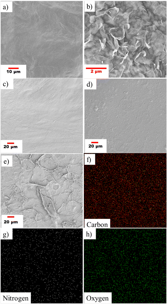 |
| | Fig. 9 SEM micrographs showing the surface morphology of the (a) GO modified membrane, (b) GO@COF0.15 modified membrane, (c) PA-COF0-GO@COF0.15 modified membrane, (d) PA-COF1-GO@COF0.15 modified membrane, and (e) PA-COF4-GO@COF0.15 modified membrane and (f)–(h) showing the surface elemental mapping of the PA-COF4-GO@COF0.15 modified membrane. | |
 |
| | Fig. 10 XPS spectra of the PA-COF0-GO@COF0.15 (a) and PA-COF4-GO@COF0.15 modified membranes (b). | |
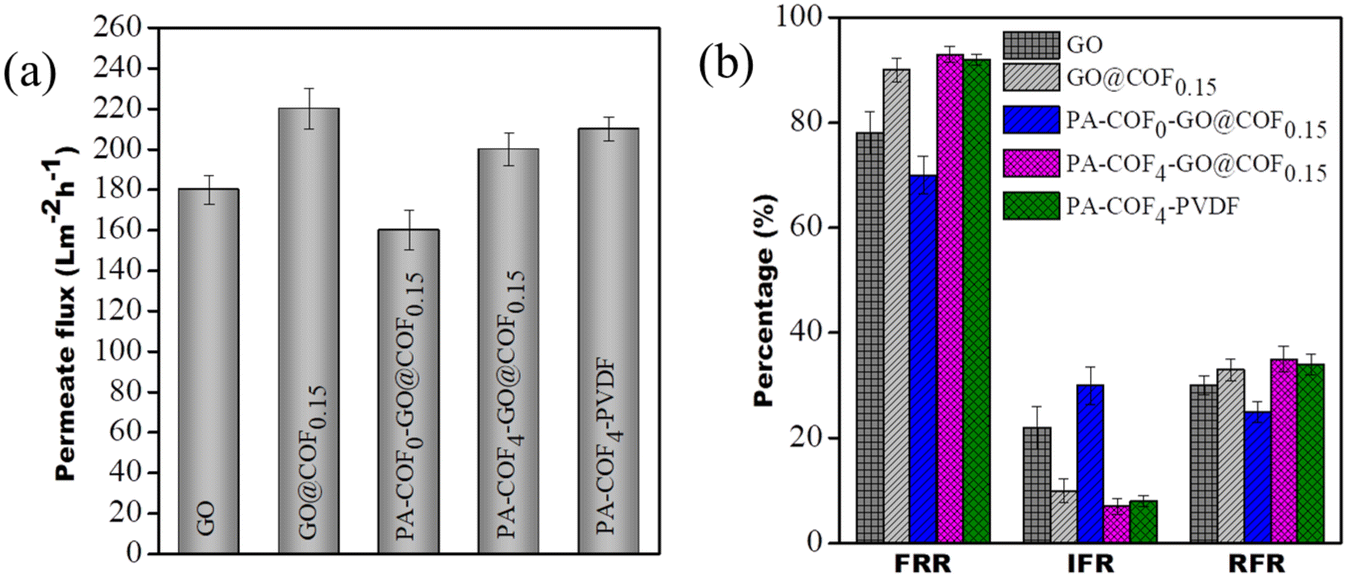
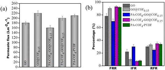
6.5. Pure water flux and antifouling properties of the membranes
The pure water flux of the GO modified membrane, GO@COF0.15 modified membrane, PA-COF0-GO@COF0.15 modified membrane, PA-COF4-GO@COF0.15 modified membrane, and PA-COF4-PVDF membrane at 0.413 MPa is 180 ± 7, 220 ± 10, 160 ± 10, 200 ± 8 LMH and 210 ± 6, respectively, as shown in Fig. 11a. From the result, it may be concluded that the addition of the COF on GO enhances its permeability by forming a direct channel for water permeation. For the PA-COF0-GO@COF0.15 modified membrane, the flux significantly decreased due to the formation of a thin PA layer on it. The PA-COF4-GO@COF0.15 modified membrane shows excellent permeability compared to the PA-COF0-GO@COF0.15 modified membrane due to the embedding of the COF into the PA layer, which leads to a more hydrophilic surface contributed by the hydroxyl, carboxyl, and amino groups of the COF as supported by the contact angle measurement shown in the ESI† (Table S2). The PA-COF4-PVDF membrane shows a slightly higher flux (210 ± 6 LMH) than the PA-COF4-GO@COF0.15 membrane (200 ± 8 LMH) due to the absence of an intermediate layer. The negatively charged surface (assessed from zeta potential measurements) of the modified membranes plays a critical role in resisting the cake formation of organic foulants on the membrane's surface. From Fig. 11b, it is noted that the fouling resistance of the GO modified membrane, GO@COF0.15 modified membrane, PA-COF0-GO@COF0.15 modified membrane, and PA-COF4-PVDF membrane is more than 78%, 90%, 75%, and 92%, respectively. The highest value, >93%, was obtained for the PA-COF4-GO@COF0.15 modified membrane, which shows that the required modified membrane is highly resistant to fouling attack. These results begin to suggest two thing: 1) that the addition of the COF improves the surface coverage of the PA layer, which is manifested by the high fouling resistance of PA-COF4-PVDF as compared to PA-COF0-GO@COF0.15 and 2) the intermediate layer (GO@COF0.15) has little role to play towards fouling resistance.
 |
| | Fig. 11 (a) Pure water flux of the GO modified membrane, GO@COF0.15 modified membrane, PA-COF0-GO@COF0.15 modified membrane, PA-COF4-GO@COF0.15 modified membrane and PA-COF4-PVDF membrane and (b) their antifouling characteristics. | |
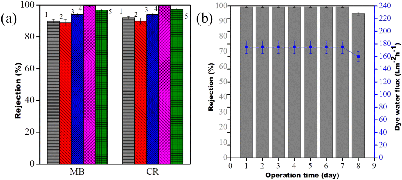
6.6. Rejection of dyes and long term stability of the membranes
100 ppm MB and 100 ppm CR solutions were used separately for the evaluation of the dye sieving performance of the modified membranes at 0.413 MPa pressure. It is noted that the GO modified membrane and GO@COF0.15 modified membrane show 90% rejection for both the dyes. The rejection is more than 94%, 97% and nearly 100% for the PA-COF0-GO@COF0.15 modified membrane, PA-COF4-PVDF membrane and PA-COF4-GO@COF0.15 modified membrane, respectively, as shown in Fig. 12a. The outstanding rejection performance of the PA-COF4-GO@COF0.15 modified membrane is due to its highly crosslinked and negatively charged surface. Moreover, the presence of the GO@COF intermediate layer in the PA-COF4-PVDF membrane aids in more rejection. To check the stability and reproducibility, the membranes were subjected to 7 days of operation. The dye water flux and the MB rejection values were reported after every 24 h cycle. It is noted that the dye water flux and rejection were reduced only from 99.50% to 95% (175 to 160 LMH), respectively, after 7 days as shown in Fig. 12b. As the cationic dye adsorbs on the membrane's surface, it hinders the water permeance and prevents further adsorption. However, in the case of the PVDF membranes this reduction is >50% as shown in Fig. S18,† and thus, it may be stated that the PA-COF4-GO@COF0.15 modified membrane can be used for long-term operation without compromising its performance.
 |
| | Fig. 12 (a) Dye rejection of the GO modified membrane (1), GO@COF0.15 modified membrane (2), PA-COF0-GO@COF0.15 modified membrane (3), PA-COF4-GO@COF0.15 modified membrane (4), and PA-COF4-PVDF membrane and (b) long term stability of the PA-COF4-GO@COF0.15 modified membrane. | |
6.7. Rejection of salts and chlorine tolerance performance of the designed TFC membranes
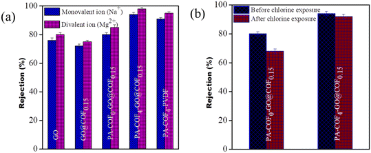
The salt rejection performances of the PA-COF0-GO@COF0.15 modified membrane and PA-COF4-GO@COF0.15 modified membrane were evaluated using a pressure enhanced FO technique by applying a small pressure of 0.068 MPa on the feed side. In this study, 2000 ppm of both monovalent and divalent salts, i.e., NaCl and Mg (NO3)2, were taken separately as draw solutions, and 20 ppm of distilled water was taken as the feed. In order to understand the performance of the TFC membrane clearly, the rejection of both the GO modified membrane and GO@COF0.15 modified membrane was also recorded in Fig. 13a. It is observed that the TFC membranes show better rejection (more than 80% for the monovalent ion and more than 85% for the divalent ion) compared to the GO-modified membrane and GO@COF0.15 modified membrane (less than 80% for both ions). The highest rejection was obtained by the PA-COF4-GO@COF0.15 modified membrane (more than 94% for the monovalent ion and more than 98% for the divalent ion) which is due to the formation of the dense (highly crosslinked) and uniform PA layer, which manifests both charged-based and pore-based sieving. To understand the role of the GO@COF0.15 intermediate layer, the rejection of the PA-COF4-PVDF membrane is also recorded in Fig. 13a. It is observed that the PA-COF4-PVDF membrane shows slightly lower rejection (91% for the monovalent ion and 95% for the divalent ion) due to the absence of the GO@COF0.15 intermediate layer.
 |
| | Fig. 13 (a) Rejection of salts by the GO modified membrane, GO@COF0.15 modified membrane, PA-COF0-GO@COF0.15 modified membrane, PA-COF4-GO@COF0.15 modified membrane, and PA-COF4-PVDF membrane and (b) chlorine tolerability of the PA-COF4-GO@COF0.15 membrane and PA-COF0-GO@COF0.15 modified membrane. | |
To investigate the tolerance of chlorine, the PA-COF4-GO@COF0.15 modified membrane and PA-COF0-GO@COF0.15 modified membrane were immersed in NaOCl solution (8000 ppm) for an hour. After that, all these membranes were thoroughly washed with ultrapure water and utilized for rejection performance. It is noted that the rejection efficiency was decreased by 12% in the case of the PA-COF0-GO@COF0.15 membrane. Meanwhile the PA-COF4-GO@COF0.15 modified membrane shows only a slight decrease of about 2% on exposure in 8000 ppm solution, as shown in Fig. 13b. This is mainly due to the embedding of the COF on the PA layer. The secondary amine of the COF, being susceptible to chlorine, helps to protect the amide bond from chlorine attack, leading to less destruction to the TFC membrane.
Discussion
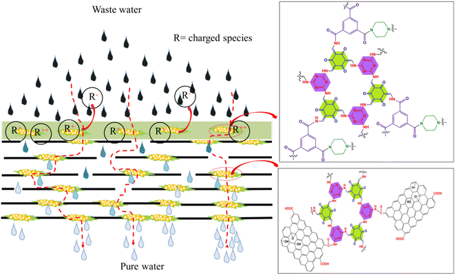
A novel strategy was adopted here to fabricate a COF embedded PA thin film composite membrane. The COF embedded PA layer was deposited onto the surface of the GO@COF0.15 membrane, which was already stitched onto the supported PVDF membrane. Thus this PA-COF4-GO@COF0.15 modified membrane shows outstanding performance in terms of permeance, fouling resistance, rejection of ions, chlorine tolerance, and long-term operation. The exceptional performance was due to the critical role of the GO@COF membrane and the embedding of the COF on the PA layer, as shown in Fig. 14.
 |
| | Fig. 14 Scheme showing the role of GO and the COF in sieving ions. | |
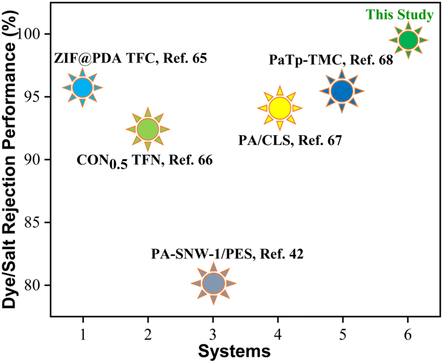
The PA-COF4-GO@COF0.15 modified membrane shows significant permeability compared to the GO-modified membrane and PA-COF0-GO@COF0.15 modified membrane due to more hydrophilicity imparted by the amine, ketone, and hydroxyl moieties of the COF. These moieties also played a vital role in harnessing negative charge on the surface. However, the PA-COF4-PVDF membrane shows a slightly higher flux (210 ± 6 LMH) than the PA-COF4-GO@COF0.15 membrane (200 ± 8 LMH) due to the absence of the GO@COF0.15 intermediate layer. Moreover, the PA-COF4-GO@COF0.15 modified membrane showed excellent fouling resistance due to its highly hydrophilic nature and negative charge on the surface as supported by zeta potential measurements (Fig. S11†). The outstanding dye rejection performance of the PA-COF4-GO@COF0.15 modified membrane is due to both size and charge-based exclusion. The highly crosslinked polyamide layer due to the amide formation between TMSCl/piperazine/COF results in efficient surface coverage of the PA layer over the GO@COF0.15 free-standing membrane. This strategy works in tandem to reject dyes and ions and is discussed below. The electrostatic interaction between the negatively charged membrane surface (Fig. S11†) and dye molecules (adsorption or repulsion depends on the charge of dye molecules) is manifested by strong rejection. The dense and highly crosslinked PA layer and the mechanically stable GO@COF0.15 membrane further assisted in the rejection of salt ions. The negatively charged membrane surface also plays a key role in sieving ions. Therefore both charge and size exclusion contribute to the rejection of salt ions in this case. At first, ions are separated by the COF-embedded dense PA layer, followed by size-based sieving aided by a mechanically stable crosslinked GO layer. The secondary amine of the COF, being susceptible to chlorine attack, protects the TFC membrane and GO@COF0.15 membrane from disintegration. Thus, the modified membrane also shows excellent rejection in a chlorine environment. Therefore, the novel PA-COF4-GO@COF0.15 modified membrane performed well as compared to the other membranes reported in the literature. A comparison of rejection of the PA-COF4-GO@COF0.15 modified membrane with a few similar type membranes reported in the literature is shown in Fig. 15 and Table 1.
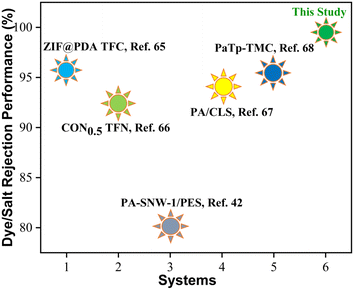 |
| | Fig. 15 Plot graph showing the performance of the PA-COF4-GO@COF0.15 modified membrane in comparison to other PA membranes reported in the literature. | |
Table 1 Comparison of the performance of the PA-COF4-GO@COF0.15 modified membrane with other PA membranes reported in the literature
| Membrane |
Type of filtration |
Permeance (Lm−2 h−1 bar−1) |
Rejection dye/salt |
Test conditions |
Ref. |
| ZIF@PDA TFC |
Cross-flow |
6.05 |
MgCl2 > 95.8 |
5 mM |
65
|
| CON0.5 TFN |
Cross-flow |
64.2 |
NaCl > 92.5 |
1 Mol L−1 |
66
|
| PA-SNW-1/PES |
Cross-flow |
19.25 |
Na2SO4 > 80% |
1 g L−1 |
42
|
| PA/CLS |
Cross-flow |
53.55 |
Na2SO4 > 94% |
1000 ppm |
67
|
| MgSO4 > 80% |
1000 ppm |
| PaTp0.05%-TMC0.2%/30 |
Cross-flow |
0.81 |
Na2SO4, MgSO4 > 96% |
1 g L−1 |
68
|
| NaCl > 93% |
1 g L−1 |
| PA-COF4-GO@COF0.15 |
Cross-flow |
50 |
MB > 99.50% |
100 ppm |
This study |
| FO |
CR > 99.75% |
100 ppm |
| NaCl > 94% |
2000 ppm |
| Mg(NO3)2 > 98% |
2000 ppm |
Conclusion
A unique, highly stable, and non-swellable GO-based membrane was achieved through chemical conjugation with a dense COF to yield GO@COF. While this construction proved to be highly efficient for water remediation when supported on a porous PVDF structure with graded pores, an in situ thin film composite membrane of COF-mediated PA (to yield PA-COF-GO@COF) showed excellent salt (>94% and >98% for monovalent and divalent ions, respectively) and dye (>99.90% for both cationic and anionic dyes) rejection and in addition, excellent resistance to fouling attack (>93%). The positioning of the PA-COF over the GO@COF membrane makes it act like a molecular sieve and helps to achieve the key attributes that are required for complete water remediation. This approach will help guide the researchers working in this field from both academia and industry.
Conflicts of interest
There are no conflicts to declare.
Acknowledgements
We express our heartfelt gratitude to SERB for its continual encouragement and financial support and to Dr. Bikramjit Basu for contact angle measurements. Sk Safikul Islam thanks SERB for NPDF (File No: PDF/2021/000629) fellowship. Last but not least, we would like to heartily acknowledge CeNSE IISc for the facilities of different characterization techniques.
References
- R. K. Chakraborti, J. Kaur and H. Kaur, Water Shortage Challenges and a Way Forward in India, J. - Am. Water Works Assoc., 2019, 111, 42–49 CrossRef
 .
.
- B. Van der Bruggen, Sustainable implementation of innovative technologies for water purification, Nat. Rev. Chem., 2021, 5, 217–218 CrossRef .
- N. A. Ahmad, P. S. Goh, L. T. Yogarathinam, A. K. Zulhairun and A. F. Ismail, Current advances in membrane technologies for produced water desalination, Desalination, 2020, 493, 114643 CrossRef .
- J. Ravi, M. H. D. Othman, T. Matsuura, M. R. I. Bilad, T. El-Badawy, F. Aziz, A. Ismail, M. A. Rahman and J. Jaafar, Polymeric membranes for desalination using membrane distillation: A review, Desalination, 2020, 490, 114530 CrossRef .
- W. Suwaileh, D. Johnson and N. Hilal, Membrane desalination and water re-use for agriculture: State of the art and future outlook, Desalination, 2020, 491, 114559 CrossRef .
- S. Bano, A. Mahmood, S.-J. Kim and K.-H. Lee, Graphene oxide modified polyamide nanofiltration membrane with improved flux and antifouling properties, J. Mater. Chem. A, 2015, 3, 2065–2071 RSC .
- K. Dey, M. Pal, K. C. Rout, S. Kunjattu, H. A. Das, R. Mukherjee, U. K. Kharul and R. Banerjee, Selective molecular separation by interfacially crystallized covalent organic framework thin films, J. Am. Chem. Soc., 2017, 139, 13083–13091 CrossRef CAS PubMed .
- T. Jain, B. C. Rasera, R. J. S. Guerrero, M. S. Boutilier, S. C. O'hern, J.-C. Idrobo and R. Karnik, Heterogeneous sub-continuum ionic transport in statistically isolated graphene nanopores, Nat. Nanotechnol., 2015, 10, 1053–1057 CrossRef CAS .
- B. Liang, H. Wang, X. Shi, B. Shen, X. He, Z. A. Ghazi, N. A. Khan, H. Sin, A. M. Khattak and L. Li, Microporous membranes comprising conjugated polymers with rigid backbones enable ultrafast organic-solvent nanofiltration, Nat. Chem., 2018, 10, 961–967 CrossRef CAS PubMed .
- S. C. O'Hern, M. S. Boutilier, J.-C. Idrobo, Y. Song, J. Kong, T. Laoui, M. Atieh and R. Karnik, Selective ionic transport through tunable subnanometer pores in single-layer graphene membranes, Nano Lett., 2014, 14, 1234–1241 CrossRef PubMed .
- R. C. Rollings, A. T. Kuan and J. A. Golovchenko, Ion selectivity of graphene nanopores, Nat. Commun., 2016, 7, 1–7 Search PubMed .
- K. H. Thebo, X. Qian, Q. Zhang, L. Chen, H.-M. Cheng and W. Ren, Highly stable graphene-oxide-based membranes with superior permeability, Nat. Commun., 2018, 9, 1–8 CrossRef CAS .
- W. Fei, M. Xue, H. Qiu and W. Guo, Heterogeneous graphene oxide membrane for rectified ion transport, Nanoscale, 2019, 11, 1313–1318 RSC .
- R. He, S. Cong, J. Wang, J. Liu and Y. Zhang, Porous Graphene Oxide/Porous Organic Polymer Hybrid Nanosheets Functionalized Mixed Matrix Membrane for Efficient CO2 Capture, ACS Appl. Mater. Interfaces, 2019, 11, 4338–4344 CrossRef CAS .
- R. Nair, H. Wu, P. Jayaram, I. Grigorieva and A. Geim, Unimpeded permeation of water through helium-leak–tight graphene-based membranes, Science, 2012, 335, 442–444 CrossRef CAS PubMed .
- Z. P. Smith and B. D. Freeman, Graphene oxide: a new platform for high-performance gas-and liquid-separation membranes, Angew. Chem., Int. Ed., 2014, 53, 10286–10288 CrossRef CAS PubMed .
- Y. Wang, X. Chen, Y. Zhong, F. Zhu, K. Loh, D. Dreyer, S. Park, C. Bielawski and R. Ruoff, The chemistry of graphene oxide, Chem. Soc. Rev., 2010, 39, 228–240 RSC .
- Y. Zhu, S. Murali, W. Cai, X. Li, J. W. Suk, J. R. Potts and R. S. Ruoff, Graphene and graphene oxide: synthesis, properties, and applications, Adv. Mater., 2010, 22, 3906–3924 CrossRef CAS PubMed .
- Y. Han, Z. Xu and C. Gao, Ultrathin graphene nanofiltration membrane for water purification, Adv. Funct. Mater., 2013, 23, 3693–3700 CrossRef CAS .
- D. W. Kim, J. Choi, D. Kim and H.-T. Jung, Enhanced water permeation based on nanoporous multilayer graphene membranes: the role of pore size and density, J. Mater. Chem. A, 2016, 4, 17773–17781 RSC .
- P. Sun, M. Zhu, K. Wang, M. Zhong, J. Wei, D. Wu, Z. Xu and H. Zhu, Selective ion penetration of graphene oxide membranes, ACS Nano, 2013, 7, 428–437 CrossRef CAS PubMed .
- J. Yang, D. Gong, G. Li, G. Zeng, Q. Wang, Y. Zhang, G. Liu, P. Wu, E. Vovk and Z. Peng, Self-assembly of thiourea-crosslinked graphene oxide framework membranes toward separation of small molecules, Adv. Mater., 2018, 30, 1705775 CrossRef .
- Y. Cao, Z. Xiong, F. Xia, G. V. Franks, L. Zu, X. Wang, Y. Hora, S. Mudie, Z. He and L. Qu, New structural insights into densely assembled reduced graphene oxide membranes, Adv. Funct. Mater., 2022, 2201535 CrossRef CAS .
- M.-L. Liu, J.-L. Guo, S. Japip, T.-Z. Jia, D.-D. Shao, S. Zhang, W.-J. Li, J. Wang, X.-L. Cao and S.-P. Sun, One-step enhancement of solvent transport, stability and photocatalytic properties of graphene oxide/polyimide membranes with multifunctional cross-linkers, J. Mater. Chem. A, 2019, 7, 3170–3178 RSC .
- J. Long, Z. Xie, S. Xue, W. Shi and Y. Liu, Highly stable and permeable graphene oxide membrane modified by carbohydrazide for efficient dyes separation, Sep. Purif. Technol., 2022, 298, 121586 CrossRef CAS .
- Y. Lu, W. Liu, J. Liu, X. Li and S. Zhang, A review on 2D porous organic polymers for membrane-based separations: Processing and engineering of transport channels, Adv. Membr., 2021, 1, 100014 CrossRef .
- M. Hu and B. Mi, Enabling graphene oxide nanosheets as water separation membranes, Environ. Sci. Technol., 2013, 47, 3715–3723 CrossRef .
- S. P. Koenig, L. Wang, J. Pellegrino and J. S. Bunch, Selective molecular sieving through porous graphene, Nat. Nanotechnol., 2012, 7, 728–732 CrossRef .
- B. Mi, Graphene oxide membranes for ionic and molecular sieving, Science, 2014, 343, 740–742 CrossRef PubMed .
- W.-H. Zhang, M.-J. Yin, Q. Zhao, C.-G. Jin, N. Wang, S. Ji, C. L. Ritt, M. Elimelech and Q.-F. An, Graphene oxide membranes with stable porous structure for ultrafast water transport, Nat. Nanotechnol., 2021, 16, 337–343 CrossRef PubMed .
- K. Guan, D. Zhao, M. Zhang, J. Shen, G. Zhou, G. Liu and W. Jin, 3D nanoporous crystals enabled 2D channels in graphene membrane with enhanced water purification performance, J. Membr. Sci., 2017, 542, 41–51 CrossRef .
- Z. Rao, K. Feng, B. Tang and P. Wu, Surface decoration of amino-functionalized metal–organic framework/graphene oxide composite onto polydopamine-coated membrane substrate for highly efficient, ACS Appl. Mater. Interfaces, 2017, 9, 2594–2605 CrossRef CAS PubMed .
- L. Chen, N. Li, Z. Wen, L. Zhang, Q. Chen, L. Chen, P. Si, J. Feng, Y. Li and J. Lou, Graphene oxide based membrane intercalated by nanoparticles for high performance nanofiltration application, Chem. Eng. J., 2018, 347, 12–18 CrossRef CAS .
- C. Xu, Y. Xu and J. Zhu, Photocatalytic antifouling graphene oxide-mediated hierarchical filtration membranes with potential applications on water purification, ACS Appl. Mater. Interfaces, 2014, 6, 16117–16123 CrossRef PubMed .
- H. Kang, J. Shi, L. Liu, M. Shan, Z. Xu, N. Li, J. Li, H. Lv, X. Qian and L. Zhao, Sandwich morphology and superior dye-removal performances for nanofiltration membranes self-assemblied via graphene oxide and carbon nanotubes, Appl. Surf. Sci., 2018, 428, 990–999 CrossRef .
- N. Wang, S. Ji, G. Zhang, J. Li and L. Wang, Self-assembly of graphene oxide and polyelectrolyte complex nanohybrid membranes for nanofiltration and pervaporation, Chem. Eng. J., 2012, 213, 318–329 CrossRef .
- J. Zhu, M. Tian, J. Hou, J. Wang, J. Lin, Y. Zhang, J. Liu and B. Van der Bruggen, Surface zwitterionic functionalized graphene oxide for a novel loose nanofiltration membrane, J. Mater. Chem. A, 2016, 4, 1980–1990 RSC .
- K. Goh, W. Jiang, H. E. Karahan, S. Zhai, L. Wei, D. Yu, A. G. Fane, R. Wang and Y. Chen, All-carbon nanoarchitectures as high-performance separation membranes with superior stability, Adv. Funct. Mater., 2015, 25, 7348–7359 CrossRef .
- H. Liu, H. Wang and X. Zhang, Facile fabrication of freestanding ultrathin reduced graphene oxide membranes for water purification, Adv. Mater., 2015, 27, 249–254 CrossRef PubMed .
- K. Geng, V. Arumugam, H. Xu, Y. Gao and D. Jiang, Covalent organic frameworks: Polymer chemistry and functional design, Prog. Polym. Sci., 2020, 108, 101288 CrossRef .
- C. Zhang, B.-H. Wu, M.-Q. Ma, Z. Wang and Z.-K. Xu, Ultrathin metal/covalent–organic framework membranes towards ultimate separation, Chem. Soc. Rev., 2019, 48, 3811–3841 RSC .
- C. Wang, Z. Li, J. Chen, Z. Li, Y. Yin, L. Cao, Y. Zhong and H. Wu, Covalent organic framework modified polyamide nanofiltration membrane with enhanced performance for desalination, J. Membr. Sci., 2017, 523, 273–281 CrossRef .
- I. Berlanga, M. L. Ruiz-González, J. M. González-Calbet, J. L. G. Fierro, R. Mas-Ballesté and F. Zamora, Delamination of layered covalent organic frameworks, Small, 2011, 7, 1207–1211 CrossRef PubMed .
- D. N. Bunck and W. R. Dichtel, Bulk synthesis of exfoliated two-dimensional polymers using hydrazone-linked covalent organic frameworks, J. Am. Chem. Soc., 2013, 135, 14952–14955 CrossRef CAS PubMed .
- S. Chandra, S. Kandambeth, B. P. Biswal, B. Lukose, S. M. Kunjir, M. Chaudhary, R. Babarao, T. Heine and R. Banerjee, Chemically stable multilayered covalent organic nanosheets from covalent organic frameworks via mechanical delamination, J. Am. Chem. Soc., 2013, 135, 17853–17861 CrossRef CAS PubMed .
- M. A. Khayum, S. Kandambeth, S. Mitra, S. B. Nair, A. Das, S. S. Nagane, R. Mukherjee and R. Banerjee, Chemically delaminated free-standing ultrathin covalent organic nanosheets, Am. Ethnol., 2016, 128, 15833–15837 Search PubMed .
- S. Mitra, S. Kandambeth, B. P. Biswal, A. Khayum, M. C. K. Choudhury, M. Mehta, G. Kaur, S. Banerjee, A. Prabhune and S. Verma, Self-exfoliated guanidinium-based ionic covalent organic nanosheets (iCONs), J. Am. Chem. Soc., 2016, 138, 2823–2828 CrossRef CAS PubMed .
- Y. Peng, Y. Huang, Y. Zhu, B. Chen, L. Wang, Z. Lai, Z. Zhang, M. Zhao, C. Tan and N. Yang, Ultrathin two-dimensional covalent organic framework nanosheets: preparation and application in highly sensitive and selective DNA detection, J. Am. Chem. Soc., 2017, 139, 8698–8704 CrossRef CAS PubMed .
- S. Wang, Q. Wang, P. Shao, Y. Han, X. Gao, L. Ma, S. Yuan, X. Ma, J. Zhou and X. Feng, Exfoliation of covalent organic frameworks into few-layer redox-active nanosheets as cathode materials for lithium-ion batteries, J. Am. Chem. Soc., 2017, 139, 4258–4261 CrossRef CAS .
- Y. Ying, D. Liu, J. Ma, M. Tong, W. Zhang, H. Huang, Q. Yang and C. Zhong, A GO-assisted method for the preparation of ultrathin covalent organic framework membranes for gas separation, J. Mater. Chem. A, 2016, 4, 13444–13449 RSC .
- M. Stolov and V. Freger, Degradation of polyamide membranes exposed to chlorine: an impedance spectroscopy study, Environ. Sci. Technol., 2019, 53, 2618–2625 CrossRef CAS .
- Y. Li, S. Li and K. Zhang, Influence of hydrophilic carbon dots on polyamide thin film nanocomposite reverse osmosis membranes, J. Membr. Sci., 2017, 537, 42–53 CrossRef CAS .
- L. Shen, S. Xiong and Y. Wang, Graphene oxide incorporated thin-film composite membranes for forward osmosis applications, Chem. Eng. Sci., 2016, 143, 194–205 CrossRef CAS .
- X. Song, L. Wang, C. Y. Tang, Z. Wang and C. Gao, Fabrication of carbon nanotubes incorporated double-skinned thin film nanocomposite membranes for enhanced separation performance and antifouling capability in forward osmosis process, Desalination, 2015, 369, 1–9 CrossRef CAS .
- C. Zhang, K. Wei, W. Zhang, Y. Bai, Y. Sun and J. Gu, Graphene oxide quantum dots incorporated into a thin film nanocomposite membrane with high flux and antifouling properties for low-pressure nanofiltration, ACS Appl. Mater. Interfaces, 2017, 9, 11082–11094 CrossRef CAS .
- A. K. Shukla, J. Alam, M. S. Alhoshan, F. A. A. Ali, U. Mishra and A. A. Hamid, Thin-Film Nanocomposite Membrane Incorporated with Porous Zn-Based Metal–Organic Frameworks: Toward Enhancement of Desalination Performance and Chlorine Resistance, ACS Appl. Mater. Interfaces, 2021, 13, 28818–28831 CrossRef PubMed .
- D. X. Trinh, N. N. Pham, P. Chammingkwan and T. Taniike, Preparation and Desalination Performance of PA/UiO-66/PES Composite Membranes, Membranes, 2021, 11, 628 CrossRef .
- Y. Wen, R. Dai, X. Li, X. Zhang, X. Cao, Z. Wu, S. Lin, C. Tang and Z. Wang, Metal-organic framework enables ultraselective polyamide membrane for desalination and water reuse, Sci. Adv., 2022, 8, 10 Search PubMed .
- S. Zhao, C. Jiang, J. Fan, S. Hong, P. Mei, R. Yao, Y. Liu, S. Zhang, H. Li and H. Zhang, Hydrophilicity gradient in covalent organic frameworks for membrane distillation, Nat. Mater., 2021, 20, 1551–1558 CrossRef .
- S. Maiti and S. Bose, Free-standing graphene oxide membrane works in tandem with confined interfacial polymerization of polyamides towards excellent desalination and chlorine tolerance performance, Nanoscale Adv., 2022, 4, 467–478 RSC .
- D. C. Marcano, D. V. Kosynkin, J. M. Berlin, A. Sinitskii, Z. Sun, A. Slesarev, L. B. Alemany, W. Lu and J. M. Tour, Improved synthesis of graphene oxide, ACS Nano, 2010, 4, 4806–4814 CrossRef .
- S. Kandambeth, A. Mallick, B. Lukose, M. V. Mane, T. Heine and R. Banerjee, Construction of crystalline 2D covalent organic frameworks with remarkable chemical (acid/base) stability via a combined reversible and irreversible route, J. Am. Chem. Soc., 2012, 134, 19524–19527 CrossRef PubMed .
- M. Bhadra, S. Kandambeth, M. K. Sahoo, M. Addicoat, E. Balaraman and R. Banerjee, Triazine Functionalized Porous Covalent Organic Framework for Photo-organocatalytic E–Z Isomerization of Olefins, J. Am. Chem. Soc., 2019, 141, 6152–6156 CrossRef .
- Y. Liang, Y. Zhu, C. Liu, K.-R. Lee, W.-S. Hung, Z. Wang, Y. Li, M. Elimelech, J. Jin and S. Lin, Polyamide nanofiltration membrane with highly uniform sub-nanometre pores for sub-1 Å precision separation, Nat. Commun., 2020, 11, 1–9 CrossRef PubMed .
- M. Qiu and C. He, Efficient removal of heavy metal ions by forward osmosis membrane with a polydopamine modified zeolitic imidazolate framework incorporated selective layer, J. Hazard. Mater., 2019, 367, 339–347 CrossRef .
- L. Xu, T. Yang, M. Li, J. Chang and J. Xu, Thin-film nanocomposite membrane doped with carboxylated covalent organic frameworks for efficient forward osmosis desalination, J. Membr. Sci., 2020, 610, 118111 CrossRef .
- J. Yuan, M. Wu, H. Wu, Y. Liu, X. You, R. Zhang, Y. Su, H. Yang, J. Shen and Z. Jiang, Covalent organic framework-modulated interfacial polymerization for ultrathin desalination membranes, J. Mater. Chem. A, 2019, 7, 25641–25649 RSC .
- F.-X. Kong, L. Yue, Z. Yang, G. Sun and J.-F. Chen, Cross-linked covalent organic framework-based membranes with trimesoyl chloride for enhanced desalination, ACS Appl. Mater. Interfaces, 2021, 13, 21379–21389 CrossRef .
|
| This journal is © The Royal Society of Chemistry 2023 |
Click here to see how this site uses Cookies. View our privacy policy here. 
 *
*