
 Open Access Article
 This Open Access Article is licensed under a
 Creative Commons Attribution 3.0 Unported Licence
In situ protonated-phosphorus interstitial doping induces long-lived shallow charge trapping in porous C3−xN4 photocatalysts for highly efficient H2 generation†
Wenchao
Wang
 a,
Lili
Du
ae,
Ruiqin
Xia
a,
Runhui
Liang
a,
Tao
Zhou
a,
Hung Kay
Lee
d,
Zhiping
Yan
a,
Hao
Luo
a,
Congxiao
Shang
a,
David Lee
Phillips
*ac and
Zhengxiao
Guo
*ab
a,
Lili
Du
ae,
Ruiqin
Xia
a,
Runhui
Liang
a,
Tao
Zhou
a,
Hung Kay
Lee
d,
Zhiping
Yan
a,
Hao
Luo
a,
Congxiao
Shang
a,
David Lee
Phillips
*ac and
Zhengxiao
Guo
*ab
aDepartment of Chemistry and HKU-CAS Joint Laboratory on New Materials, The University of Hong Kong, Hong Kong SAR, P. R. China. E-mail: zxguo@hku.hk; phillips@hku.hk
bZhejiang Institute of Research and Innovation, The University of Hong Kong, Hangzhou 311305, P. R. China
cGuangdong-Hong Kong-Macao Joint Laboratory of Optoelectronic and Magnetic Functional, Hong Kong SAR, P. R. China
dDepartment of Chemistry, The Chinese University of Hong Kong, Shatin, New Territories, Hong Kong SAR, P. R. China
eSchool of Life Science, Jiangsu University, Zhenjiang 212013, P. R. China
First published on 5th December 2022
Abstract
Efficient photocatalytic solar-to-H2 conversion is pivotal to zero-carbon energy supply. Graphitic carbon nitride (g-C3N4) is a promising visible-light photocatalyst but suffers from intrinsic electron–hole recombination and deep-charge trapping, limiting its efficiency. Here, we show a synergistic strategy of porosity, vacancy and shallow(trapping)-state engineering to enrich catalytic sites and promote the lifetime of active electrons by thermochemical treatment and phosphorus-interstitial-doping. The latter enhances the electron delocalization in the π-conjugate polymeric structure. The optimized photocatalyst shows a ∼800% increase in H2 generation (6323 μmol h−1 g−1) and an about 5-fold increase in quantum efficiency (QE420 nm = 5.08%). The superior performance is attributed to the long-lived shallow charge trapping, as a result of proton-feeding to the coordinated phosphorus site during the photocatalytic reaction, which enhances the photogenerated carrier lifetime and positively optimizes the band structure of the catalyst. Femtosecond transient absorption spectroscopy reveals a doubling lifetime of shallow-trapped charges (∼405.5 ps), favoring high mobility for electron-involved photocatalytic H2 generation. This work provides a new mechanism for improving charge carrier dynamics and photocatalytic performance.
Broader contextPhotocatalytic water-splitting holds great potential for the cost-effective large-scale production of green hydrogen (H2) from abundant solar energy and water molecules. The key challenges are to develop a highly efficient and stable photocatalyst that can promote the effective photodynamics of charge carriers, i.e. electrons/holes (e−/h+), to drive their sufficient separation and bulk-to-surface transfer, while maintaining its performance durability. Herein, we report an effective atomic heterojunction formed by porosity-stabilised interstitial phosphorus(P)-doping, along with its in situ protonation, to induce electron shallow-trap states in a carbon-lean graphitic carbon nitride (g-C3−xN4) photocatalyst. Experiments and theoretical calculations show that the key roles of the in situ protonated interstitial P are in (1) restraining undesirable deep charge trapping, (2) prolonging the lifetime of the active charges and (3) forming a spin-enhanced structure. The resulting catalyst achieved 800% enhancement of the H2 generation rate at 6323 μmol h−1 g−1 with an internal quantum efficiency of 31.8% under visible-light excitation. Due to the durable “–N–P![[double bond, length as m-dash]](https://www.rsc.org/images/entities/char_e001.gif) N–” junction for efficient charge transfer and the abundant proton source in water, the as-synthesized catalyst shows superior photostability for H2 production, compared to its pristine counterpart. This report provides new insights into the proton-/electron-involved photocatalytic H2 production mechanism by transient time-resolved spectroscopic studies, and provides a novel in situ proton-assisted mechanistic model for effective solar-to-H2 conversion in solution. N–” junction for efficient charge transfer and the abundant proton source in water, the as-synthesized catalyst shows superior photostability for H2 production, compared to its pristine counterpart. This report provides new insights into the proton-/electron-involved photocatalytic H2 production mechanism by transient time-resolved spectroscopic studies, and provides a novel in situ proton-assisted mechanistic model for effective solar-to-H2 conversion in solution.
|
Introduction
Photocatalytic water-splitting is highly desirable to generate green H2 with net-zero carbon emission.1–5 Considerable efforts have been devoted to the process since its inception in 1970s,6 where both thermodynamic requirements (e.g., band-gap, redox potential vs. H+/H2) and dynamic efficiency (e.g., charge separation/accumulation) are highly important.7–10 Many investigations have focused on the development of semi-conductive materials with suitable band structures that can accelerate charge carrier migration and enhance optical absorption, as outlined recently.11–14 The engineering of single-component photocatalysts, e.g. by vacancy-assisted electronic structure tuning, phase transformation and single-atom doping, has recently been rekindled to boost photocatalytic performance with well-tuned band edges and enriched catalytic sites. However, even with well-aligned band-structures, single-component photocatalysts often show insufficient driving force for water-splitting due to their photodynamic losses, e.g., by intrinsic emission and deep charge trapping. On the other hand, two-component photocatalysts (e.g., TiO2/MoS2, WO3/BiVO4 and MoS2/WS2) are under popular consideration to enhance efficiency by fast interfacial charge carrier transfer via a built-in heterojunction.15–17 Unfortunately, as with most of the Type-II and Z-scheme heterojunction photocatalytic systems, the enhanced dynamic efficiency comes at the cost of a reduced redox potential when two coupled catalysts exhibit staggered band edges. It is very challenging to develop a catalyst for the dynamically effective conversion of solar energy into H2 with high redox capability and stability.With due consideration of redox-potential tuning and enrichment of catalytic centers, it is found that two-dimensional conjugated polymeric materials are attractive candidates for high-efficiency catalysis.18 For instance, graphitic carbon nitride (g-C3N4) shows tremendous promise for cost-effective photocatalytic water-splitting due to its superior visible-light activity and tunable atomic structure.19–22 However, its overall performance for water-splitting is limited by the rapid decay of the excited states via charge carrier recombination, deep trapping and poor redox potential, as the band-edge is close to the H+/H2 potential.23 The intrinsic deep-charge trapping features of the pristine g-C3N4 constrain active electrons transport, directly reducing the dynamic efficiency.24 A viable strategy to suppress deep trapping is to create long-lived active electrons via promotion of electron shallow trapping at a relatively high energy level. In our previous studies, heterojunctions and near-field assistance were shown to improve the charge separation lifetime and also promote shallow charge trapping of g-C3N4, respectively, leading to efficient visible-light-driven photocatalytic H2 production.25–27 The enhancement of hot-carrier production was verified by Xie et al. over an order-to-disorder transformation of a g-C3N4 photocatalyst, via accelerated exciton dissociation.28 In addition, defect engineering can be an effective way of adjusting the Fermi level of semiconductors to improve interfacial charge carrier transfer and electron–hole separation. Ye et al. have reported a widened Fermi level mismatch strategy by tuning the N-vacancy density of a g-C3N4-based material for efficient photocatalysis.29 Moreover, atomic vacancies of g-C3N4 play an important role in exposing catalytic and binding sites to enhance heteroatomic coordination in new chemical interactions. For example, Zeng and co-workers impart nitric oxide photo-conversion activity to C-vacancy mediated Pd-doped g-C3N4, as a result of ready formation and stabilization of a Pd–N bond.30 Hence, defect engineering is an effective approach to bind heteroatoms and tune band-edge positions. However, it is unclear if such an atomic defect may promote high-frequency and/or lifetime of shallow trapping and change the charge carrier transport pathway.
Recently, considerable effort has also been devoted to non-metallic heteroatom (e.g., S, O and B) doping of g-C3N4 to boost photocatalytic water-splitting by the engineering of effective catalytic sites and band edges.31–33 For example, Shen et al. reported a self-Z-scheme photocatalyst of boron-doped and pristine g-C3N4 with a well-tuned band structure to drive photocatalytic overall water-splitting in the presence of Pt and Co(OH)2 co-catalysts.34 Notably, this boron doping strategy not only enhances the visible-light absorption efficiency of g-C3N4 but also accelerates the interfacial charge carrier mobility via band edge alignment. Other research suggested that the ideal dopants should not perturb the ordered microstructure of the semiconducting host in order to extend the delocalization of the π-electrons.35 Different from boron, phosphorus (P) is theoretically predicted to occupy preferably the “interstitial sites” of g-C3N4 between two adjacent tri-s-triazine units, creating a P–N bridged bond, which may act as a new carrier migration channel to promote charge mobility between the two adjacent heptazine units.36 Moreover, it is also predicted that this interstitially P-doped structure can result in several potentially beneficial effects: (1) a downshift of the CB edge by ∼0.25 eV without altering the VB edge, leading to a narrowed band-gap of 2.3 eV, extending the absorption edge by about 80 nm, though this also reduces the driving force for proton reduction; (2) an isolated P 3p state localized ∼0.15 eV below the LUMO of the host g-C3N4, which may induces shallow trapping; and (3) delocalized/noncoplanar HOMO and LUMO distributions around the P and the adjacent N atoms, respectively, which facilitate charge separation and inhibit charge recombination. However, such potentially beneficial effects have not been fully realized in practice, to the best of our knowledge. In addition, another important fundamental issue is how protons are involved in photocatalysis (not just as a reactant), as H2 is usually produced by electron-involved proton reduction in an aqueous solution.
With full consideration of the above, we resorted to a heuristic strategy of tuning the band structure and charge carrier migration by both porosity engineering and phosphorus-interstitial doping of g-C3N4via a facile thermochemical treatment method. The resulting P-interstitially-doped carbon-defective holey g-C3N4 (Pi-Ho@C3−xN4) is an effective photocatalyst with enriched catalytic sites, substantially improved redox capacity and photo-dynamics for H2 generation. The increased surface area and pore distribution were demonstrated by the holey and ultrathin structure of g-C3N4 with abundant carbon vacancies and catalytic centres. Efficient charge separation was achieved in Pi-Ho@C3−xN4, compared with the bulk g-C3N4. Atomic phosphorus embedded in the interstitial sites of the adjacent heptazine units synergistically promotes the shallow trapping of the hot electron carriers and increases the conduction band potential to enhance both the kinetic and thermodynamic driving forces for H2 generation. Interestingly, we found that the in situ protonation plays a significant role in optimizing the band structure of the Pi-Ho@C3−xN4 catalyst and prolonging the photogenerated carrier lifetime after forming a proton-phosphorus coordinated ligand. Density Functional Theory (DFT) based simulations reveal the disappearance of a deep trap state and the emergence of a shallow trap state in a proton-fed phosphorus interstitial bridge. Femtosecond transient absorption spectroscopy (fs-TAS) in situ confirms the highly efficient charge carrier separation and accumulation of photocatalytically long-lived shallow trap states in water as well. As a result, the photoactivity of Pi-Ho@C3−xN4 was significantly enhanced by over 800% (6323 μmol h−1 g−1), compared with that of bulk g-C3N4 (790 μmol h−1 g−1). The design approach provides an effective pathway for the engineering of highly efficient and stable photocatalytic systems for visible-light-driven H2 generation.
Results and discussion
Fig. 1a shows the facile thermochemical process and the resulting structures for bulk g-C3N4 (BCN), holey g-C3−xN4 (Ho@C3−xN4) and Pi-Ho@C3−xN4 photocatalyst synthesis. Briefly, in step I, the BCN sample was synthesized by conventional thermal polycondensation of urea in a muffle furnace (Fig. S1a, see the ESI†). Then, the sample was thermochemically exfoliated at 520 °C in an air atmosphere to prepare few-layer (FCN), ultrathin (UCN) and Ho@C3−xN4 samples, respectively (step II). Finally, red phosphorus vapour doping was conducted under an inert (Ar) atmosphere (step III Fig. S1b, see the ESI†) to produce Pi-Ho@C3−xN4 catalysts. Both scanning electron microscopy (SEM) and scanning transmission electron microscopy (STEM) images revealed the morphology of the as-synthesized samples, as shown in Fig. 1b–i. Briefly, the SEM and STEM images of BCN in Fig. 1b and e show relatively thick 2D micro-sheets. The few-layer and the ultrathin structures of g-C3N4 were obtained after thermochemical exfoliation for 2 and 4 hours, respectively (Fig. S2, see the ESI†). After the thermochemical treatment for 6 h, it is clearly seen that a holey structure was achieved with clean and transparent surfaces (Fig. 1c and f). Similarly, thus a holey feature persisted in the Pi-Ho@C3−xN4 sample (Fig. 1d and g). The ringed SAED pattern indicates the existence of an amorphous structure of the Pi-Ho@C3−xN4 sample, with only short-range orders; the main diffraction “rings” corresponding to the (002) and (100) crystal planes with d-spacing values of ∼0.33 and 0.62 nm, respectively (Fig. 1h).37,38 X-ray maps and the high-resolution image show the uniform distribution of C, N and P elements and the micro-sheet structure of Pi-Ho@C3−xN4 (Fig. 1i). The linear scan shows strong C and N signals (Fig. S3, see the ESI†), and notably, a weak P signal, which reflects well the general chemical structure and the relatively low concentration of phosphorus. The photographic insets (Fig. 1b–d) show the expanded volumes of the non-exfoliated BCN, exfoliated Ho@C3−xN4 and Pi-Ho@C3−xN4 samples at the same mass (20 mg), suggesting the successful exfoliation of g-C3N4 from the bulk to the holey ultrathin structure. In addition, the colour of the resulting powders changes from light yellow for BCN, white for Ho@C3−xN4 to light grey for Pi-Ho@C3−xN4, demonstrating that the phosphorus doping did affect the optical properties and the electronic structure of the photocatalyst.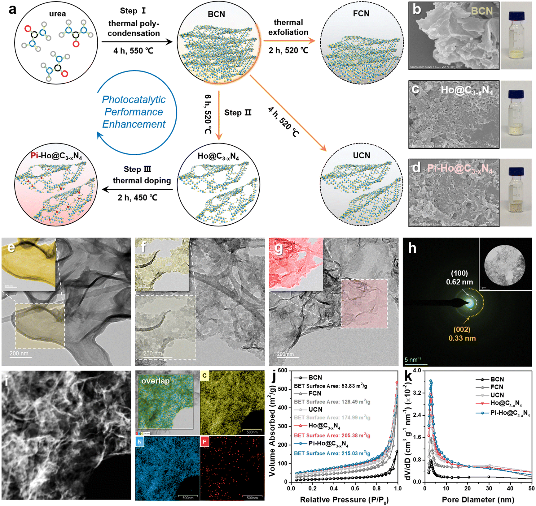 | ||
| Fig. 1 (a) Schematic illustration of the synthesis process of Pi-Ho@C3−xN4; SEM images of (b) BCN, (c) Ho@C3−xN4 and (d) Pi-Ho@C3−xN4 and the corresponding digital photograph of each catalyst (20 mg); STEM images of (e) BCN, (f) Ho@C3−xN4 and (g) Pi-Ho@C3−xN4; (h) SAED pattern of Pi-Ho@C3−xN4; (i) STEM EDX-mapping area for C, N and P elements distributed in the Pi-Ho@C3−xN4 sample; (j) Nitrogen adsorption–desorption isotherms; (k) Corresponding pore diameter distribution of BCN, FCN, UCN, Ho@C3−xN4 and Pi-Ho@C3−xN4. | ||
Nitrogen adsorption–desorption isotherms demonstrated an increased surface area in the order from Pi-Ho@C3−xN4 ≈ Ho@C3−xN4 > UCN > FCN > BCN (Fig. 1j). The specific surface area of Pi-Ho@C3−xN4 (215.03 m2 g−1) and Ho@C3−xN4 (205.38 m2 g−1) is the highest, compared with the ultrathin g-C3N4 (174.99 m2 g−1) and the few-layer g-C3N4 (128.49 m2 g−1), and is almost four times greater than that of the BCN sample (53.83 m2 g−1). It is well known that the higher the surface area, the more the catalytic centres and the faster the mass transfer. Due to the abundant pores, both Ho@C3−xN4 and Pi-Ho@C3−xN4 reveal a Type-IV isotherm of a highly mesoporous structure. Compared with the BCN, the pore diameters of the exfoliated samples show various levels of increase at ∼2.6 nm and towards ∼5 nm. In particular, both Ho@C3−xN4 and Pi-Ho@C3−xN4 display far great levels of the mesopores by both the broadness and sharpness of the curves (Fig. 1k). X-ray diffraction (XRD) patterns of BCN, Ho@C3−xN4 and Pi-Ho@C3−xN4 show two distinct peaks around 27.2° and 12.8°, which can be indexed to the π–π interlayer stacking (002) and tri-s-triazine unit (100) planes, respectively (Fig. 2a).39,40 This suggests that the conjugated aromatic groups maintain periodic stacking. Importantly, a slight right-shift (∼0.5°) of the (002) diffraction was observed for Ho@C3−xN4 and Pi-Ho@C3−xN4 samples, indicating a reduced interlayer distance.41 UV-Vis diffuse reflectance spectroscopy (UV-Vis DRS) revealed the direct influence of the structural disorder on photon absorption, as shown in Fig. 2b. Compared to BCN, Ho@C3−xN4 shows an evident blue shift of the absorption edge toward a smaller wavelength, which was ascribed to the following two reasons: (i) a quantum confinement effect and (ii) a conjugation unit reduction caused by the in-plane holes.42 In contrast, Pi-Ho@C3−xN4 shows stronger visible-light absorption than that of Ho@C3−xN4 due to P doping. The bandgap energy (Eg) was calculated to be 2.82 eV for BCN, 3.00 eV for Ho@C3−xN4 and 2.94 eV for Pi-Ho@C3−xN4 using Tauc plots (Fig. 2c).
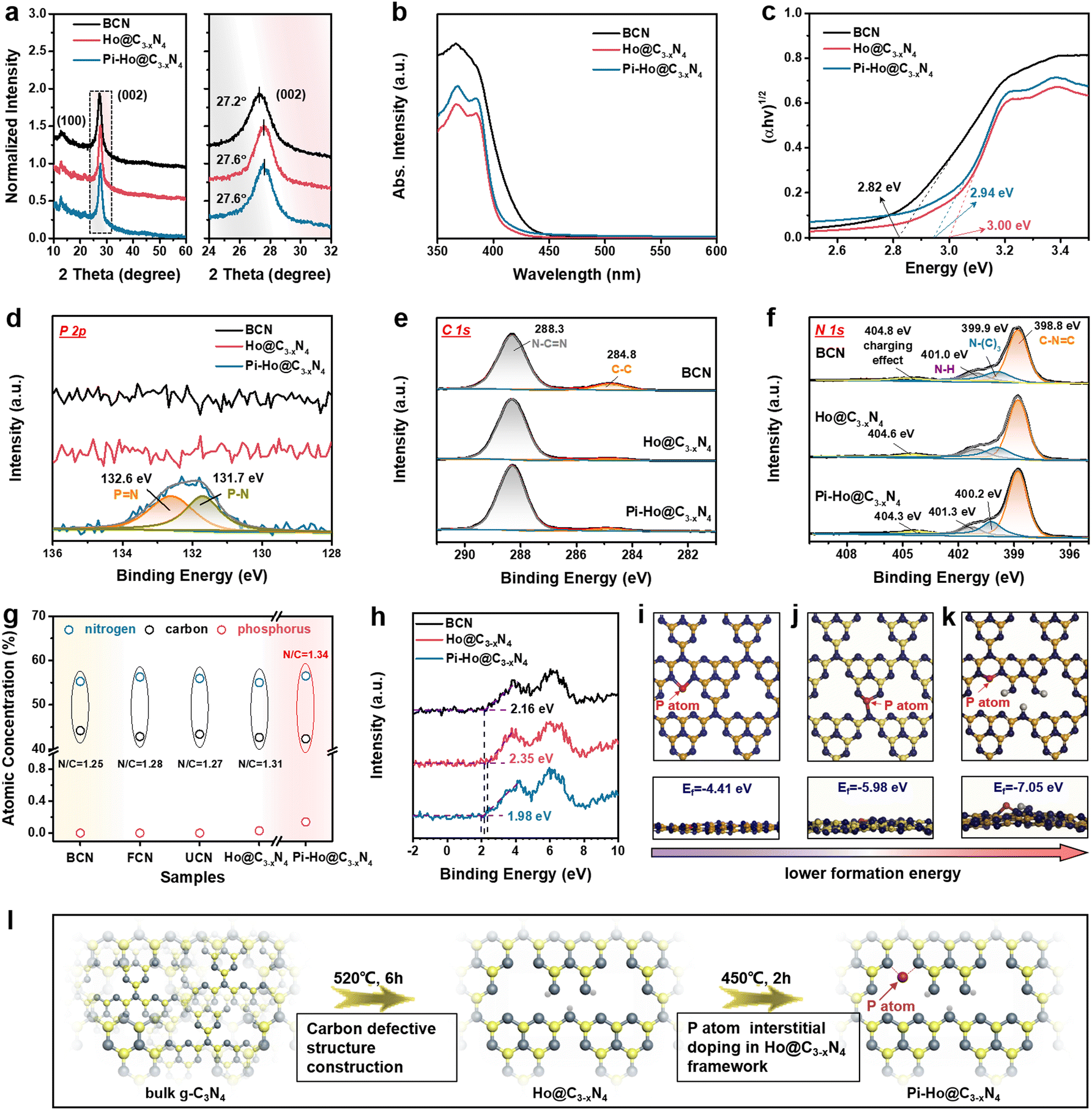 | ||
| Fig. 2 (a) XRD patterns; (b) UV-Vis DRS; (c) Tauc plots derived from (b); (d) high resolution XPS spectra of P 2p; (e) high resolution XPS spectra of C 1s. (f) High resolution XPS spectra of N 1s. (g) Atomic concentration of C, N and P in BCN, FCN, UCN and Ho@C3−xN4 and Pi-Ho@C3−xN4, respectively. (h) VB XPS spectra of BCN, Ho@C3−xN4 and Pi-Ho@C3−xN4; (i–k) atomic schemes (top and side views) of Pi-Ho@C3−xN4 with phosphorus atoms at the most energetically favourable sites. (l) Proposed atomic structure evolution. | ||
X-ray photoelectron spectroscopy (XPS) was employed to investigate the surface chemical structures of BCN, Ho@C3−xN4 and Pi-Ho@C3−xN4, as shown in Fig. 2d–f. XPS wide spectra showed that the N and C are the main components of the BCN, Ho@C3−xN4 and Pi-Ho@C3−xN4, whereas no clear phosphorus signal can be found in the Pi-Ho@C3−xN4 framework due to its relatively low concentration (Fig. S4, see the ESI†). However, the high resolution and curve fitting of P 2p spectra show two P-relevant binding energies around 131.7 and 132.6 eV in Pi-Ho@C3−xN4 (Fig. 2d), corresponding to the P–N and PN coordination, respectively. Furthermore, the C 1s and N 1s XPS spectra (Fig. 2e and f) show similar characteristic peaks of g-C3N4. As shown in Fig. 2e, the two peaks centered at 284.8 and 288.3 eV of the C 1s can be assigned to graphitic carbon (C–C coordination) and sp2-hybridized carbon (N–CN), respectively.43 The N 1s spectrum can be discretely divided into four peaks, respectively, attributed to the sp2-bonded nitrogen in C–NC (398.8 eV), the tertiary N atoms (399.9 eV), the terminal N–H group (401.0 eV) and the positive charge localization in the heterocycles (404.8 eV) (Fig. 2f).44 Notably, the slight shift of the N–(C)3, N–H and the positive charge localization are likely due to the phosphorus-doping induced charge redistribution in the g-C3N4 matrix. Conventionally, a P dopant prefers to substitute the bay-carbon sites in a triazine unit, forming three P–N bonds.45–47 However, for P interstitial doping, the P atom would only bond to two N atoms. Because of the higher electronegativity of the N atom than that of the P atom, fewer P–N bonds imply higher electron density remaining at the P atom,48 or a lower P–N binding energy, as indeed observed for the Pi-Ho@C3−xN4 (131.7 and 132.6 eV for the P–N and PN bonds, respectively, Fig. 2d), compared to its conventional phosphorus substitutionally doped counterpart (131.9 and 133.0 eV for the P–N and PN bonds, Fig. S5, see the ESI†). The observation indicates that P-doping is mainly at the interstitial site in Pi-Ho@C3−xN4.
Fourier transformation infrared (FTIR) spectroscopy was used to investigate further the chemical structure and phosphorus-interstitial-doping of the as-prepared catalysts (Fig. S6, see the ESI†). The characteristic vibration bands at 1200–1700 cm−1 are from the stretching mode of the C–N vibrations (Fig. S6a, see the ESI†).49 Furthermore, the sharp peak centred at 800 cm−1 corresponds to the intrinsic heptazine unit of the carbon nitride structure.50 In addition, the broad absorption bands at 3000–3400 cm−1 are caused by the absorbed H2O molecules and the uncondensed amino group.51 The vibration peak is around 667 cm−1, which is close to the range observed for g-C3N4 in the literature,47 and hence attributable to the stretching mode of the P–N bond. The slight shift (to a higher frequency) indeed reflects the different (stronger) bonding environment for the P-doping at the interstitial site (Fig. S6b, see the ESI†). The neighbouring signal, ∼646 cm−1, comes from the heptazine structure, which exists in all the samples. Importantly, both P–N and PN coordination was found from the high resolution XPS spectra for P 2p in Pi-Ho@C3−xN4 (Fig. 2d), which is a valid indication that the phosphorus atoms may are located at the interstitial site between two adjacent tri-s-triazine units, forming a new “–N–PN–” bridging channel. To further clarify the phosphorus substitution site in g-C3N4, both the interstitial and the C-vacancy sites were evaluated for P doping, by the Vienna Ab initio Simulation Package (VASP). The corresponding atomic schemes (top and side views) of the P-doped Ho@C3−xN4 with the most energetic configurations are shown in Fig. 2i–k. It is noted that the formation energy Ef of the interstitial P-doped g-C3N4 (Ef = −7.05 eV) is the most negative among that of the conventional P-doped g-C3N4 (via replacing carbon atom, Ef = −5.98 eV) and the interstitial P-doped without a carbon vacancy (Ef = −4.41 eV), respectively.52 Hence, the phosphorus atoms are preferentially located at the interstitial site with a new “–N–PN–” connection.
Further elemental analysis of the XPS results revealed deep insight into the existence of carbon vacancies, as evident from the atomic ratio of N/C (Fig. 2g). The N/C ratio increases from 1.25 for BCN, 1.28 for FCN, 1.27 for UCN to 1.31 for Ho@C3−xN, which can be ascribed to the removal of intrinsic carbon impurities and creation of the carbon vacancies during thermochemical exfoliation. Therefore, Fig. 2e shows negligible C–C coordination in Ho@C3−xN4 and Pi-Ho@C3−xN4, respectively, compared to the BCN. Moreover, both Ho@C3−xN4 and Pi-Ho@C3−xN4 show a higher N/C ratio, due to the enriched carbon vacancy structure. As illustrated in Fig. 2l, the Ho@C3−xN4 sample was obtained under 520 °C, followed by the phosphorus-interstitial-doping in the g-C3N4 structure. This interstitial doped phosphorus can provide a new “–N–PN–” chemical channel on the Pi-Ho@C3−xN4 sheets to boost charge separation. To investigate the band positions of the as-synthesized catalysts, valence band (VB) XPS spectra were used to estimate VB positions (Fig. 2h). Compared with bulk g-C3N4 (BCN, ∼2.16 eV), Ho@C3−xN4 displayed the most positive potential edge at ∼2.35 eV. For Pi-Ho@C3−xN4, the phosphorus interstitial doping induced a VB shift to 1.98 eV.
Fig. 3a shows the visible-light-driven (λ > 400 nm) H2 production characteristics of the as-prepared catalysts with TEOA (10 vol%) as the hole scavenger and Pt (co-catalyst, 3 wt%) as the electron acceptor. Pt nanoclusters were anchored on the Pi-Ho@C3−xN4 surface by the photoreduction method as shown in Fig. S7 (see the ESI†), which shows the uniform distribution of Pt nanoclusters and the nanosheet structure of Pi-Ho@C3−xN4 by STEM EDX-mapping. As expected, Ho@C3−xN4 presented the highest photocatalytic hydrogen generation activity (2746 μmol h−1 g−1) than those of BCN (790 μmol h−1 g−1), FCN (1014 μmol h−1 g−1) and UCN (2187 μmol h−1 g−1), in correspondence with the improvements from the increased surface area, catalytic site density and high redox capability. By optimization of the P-doping level, the photocatalytic H2 production rate reached a maximum of 6323 μmol h−1 g−1 over the Pi-Ho@C3−xN4 photocatalyst (Fig. 3a), which is up to 8 times greater than the BCN sample. As shown in Fig. S8 (see the ESI†), EDX measurement reflected the actual P-doping content in the Pi-Ho@C3−xN4 samples. However, an excess amount of P dopants may form potential recombination centers for electron–hole pairs.53 Hence, the H2 production rate decreases to 4249 μmol h−1 g−1 when the phosphorus precursor was increased to 250 mg (Fig. 3b). The control experiment of the thermal doping temperature was evaluated in Fig. S9 (see the ESI†), showing that the optimal temperature is 450 °C. The photocatalytic H2 production characteristics under simulated sunlight (AM 1.5) and visible-light irradiation (λ > 400 nm) are compared in Fig. S10 (see the ESI†). The histograms show that the H2 production rate reduces in the order Pi-Ho@C3−xN4 > Ho@C3−xN4 > BCN.
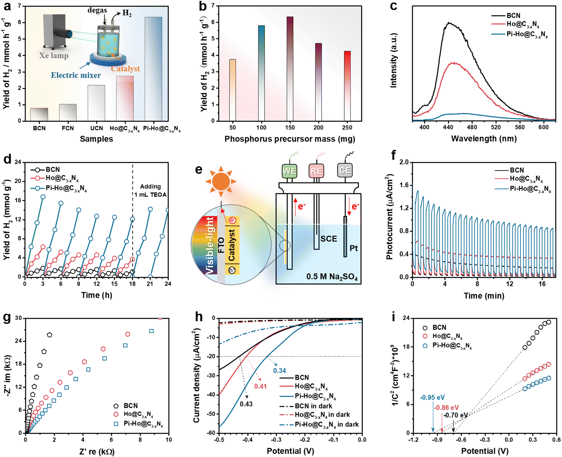 | ||
| Fig. 3 (a) Comparison of the H2 evolution rates of different catalysts and inset: Schematic of the photocatalytic measurement system; (b) H2 evolution rate as a function of red P precursor mass (50–250 mg); (c) steady-state photoluminescence (PL) emission under 355 nm laser flash; (d) cyclic runs of photocatalytic H2 generation over the BCN, Ho@C3−xN4 and Pi-Ho@C3−xN4, respectively; (e) schematic of a photoelectrochemical cell (working electrode: photocatalyst/FTO; counter electrode: Pt foil; reference electrode: SCE), and corresponding photoelectrochemical measurements: (f) photocurrent, (g) Nyquist plots, (h) LSV curves and (i) Mott–Schottky plots. | ||
On the other hand, the photocatalytic activity is also strongly influenced by charge carrier kinetics and separation. Fig. 3c shows the steady-state photoluminescence (PL) emission spectra of the BCN, Ho@C3−xN4 and Pi-Ho@C3−xN4 in pure water for the investigation of electron/hole recombination. The radiative peaks around 450 and 400 nm are related to the lowest singlet exciton and excimer emissions, respectively.54 Notably, the dramatic PL quenching of the Pi-Ho@C3−xN4, relative to BCN and Ho@C3−xN4, implies effective survival of the excited states with a high population of active species, which can only be attributed to efficient charge transport boosted by the “–N–PN–” channel. The quantum efficiency (QE) at 420 nm of BCN, Ho@C3−xN4 and Pi-Ho@C3−xN4 was estimated to be 0.87, 2.64 and 5.08%, respectively. The internal quantum efficiency (IQE) of Pi-Ho@C3−xN4 photocatalyst (3 wt% Pt as a co-catalyst) reaches 31.8% at 400 nm, compared to 5.7% for the BCN under the same conditions. In addition, the photostability of the as-prepared catalysts was also investigated, as noted in Fig. 3d. The photoactivity was largely recovered, from ∼72% to 83%, after addition of only 1.0 mL of fresh electron donor (TEOA) into the system at the end of the sixth cycle. This indicates that much of the reduction in H2 generation is due to the exhaustion of the electron donor (TEOA), rather than the degradation of the catalyst. The almost unchanged FTIR spectra (Fig. S11, see the ESI†) after the 18 h reaction further confirm the high stability of the Pi-Ho@C3−xN4 structure for visible-light-driven H2 production. Morphological studies from SEM and high-resolution STEM (HRSTEM) demonstrate the holey structure and the transparent surfaces after the photostability test (Fig. S12a–c, see the ESI†). In addition, Pt nanoclusters, as co-catalyst, were deposited on the Pi-Ho@C3−xN4 under visible-light irradiation as shown in Fig. S12b (see the ESI†). The HRSTEM image in Fig. S12c (see the ESI†) demonstrates that these 5–10 nm highly crystallized Pt nanoclusters prefer to grow along the (111) crystal planes.55 Indeed the postmortem structural analysis of the catalyst by SEM and STEM (Fig. S12, ESI†) shows little change in the structural integrity, which further supports the long-term operational potential of the catalyst. A comparison of the H2 production rate with the reported conventional phosphorus substitutional doped and other heteroatom doped g-C3N4 catalysts (mostly using Pt as a co-catalyst) in the literature is shown in Table S1 and S2 (see the ESI†), respectively. It is clear that Pi-Ho@C3−xN4 shows much more effective H2 production than that of the other (g-C3N4)-based photocatalysts under similar experimental conditions.
To understand the intrinsic charge transport of the as-synthesized photocatalysts, photoelectrochemical properties were characterized by the photocurrent, electrochemical impedance spectroscopy (EIS), linear sweep voltammetry (LSV) and Tafel plot, using a 0.5 M Na2SO4 aqueous solution without a hole scavenger or a co-catalyst (Fig. 3f–i). Fig. 3e shows a schematic diagram of the conventional three-electrode system in a photoelectrochemical cell. According to past reports, the highest photocurrent manifests the most efficient electron–hole separation.56 The long-term transient current (i–t) curves were measured to show the photo-response and stability in Fig. 3f. Due to the interaction equilibrium required between the electrolyte and the electrode in the early stage, all samples show an apparent decline of photocurrent density (PCD), followed by good stability after about 12 min. As expected, the strongest PCD value was observed at the Pi-Ho@ C3−xN4 electrode, suggesting the most efficient electron–hole separation under visible-light irradiation. Tafel, EIS and polarization curves were employed to investigate the charge transfer efficiency and kinetics. Typically, for the Nyquist plots, the largest diameter reveals the highest charge transportation resistance.57Fig. 3g shows clearly that the diameter of the Nyquist plot is in the following order: Pi-Ho@C3−xN4 < Ho@C3−xN4 < BCN, suggesting the lowest resistance of the Pi-Ho@C3−xN4 for the highest carrier transportation efficiency. Moreover, the polarization profiles of the catalysts were obtained from LSV under dark and visible light irradiations, respectively (Fig. 3h). The different photocurrent densities illustrate the enhanced visible-light-driven photocatalytic kinetics for water splitting in comparison with that under dark conditions. The overpotential (at −20 μA cm−2) of the H2 production of the Pi-Ho@C3−xN4 (0.34 V) is much lower than that of both the BCN (0.43 V) and the Ho@C3−xN4 (0.41 V) under visible-light exposure, demonstrating the important roles of the phosphorus-interstitial-doping and the defective holey carbon structure for radically improving photocatalytic activity and kinetics.
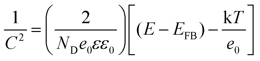
To gain further insight into the relationship between the carrier density (ND) and the flat band potential (EFB), Mott–Schottky plots were obtained by fitting the x-axis intercept of the linear section of 1/C2vs. potential, as shown in Fig. 3i. The EFB values of the BCN, Ho@C3−xN4 and Pi-Ho@C3−xN4 were determined to be −0.70, −0.86, and −0.95 V vs. SCE (saturated calomel electrode), corresponding to the −0.76, −0.92 and −1.01 eV of the conduction band (CB) positions, respectively (Fig. 4a). Therefore, owing to the most negative CB potential, the Pi-Ho@C3−xN4 photocatalyst possesses the most efficient driving force for photocatalytic proton reduction among the catalysts under consideration. Moreover, the exchange current density (J0) was investigated by Tafel-polarization (Fig. S13, see the ESI†). Pi-Ho@C3−xN4 possesses the highest J0 at the cathodic branch, favouring the solar-driven reduction reaction and the carrier kinetics. Taking the bandgap and the UV-vis DRS into consideration, the remarkable difference in the H2 production rate may be attributed to the improvements of the band-edge, charge carrier separation (via phosphorus-interstitial-doping) and active site density (via defective porosity engineering). In addition, the valence band (VB) potentials of the BCN (2.06 eV), Ho@C3−xN4 (2.08 eV) and Pi-Ho@C3−xN4 (1.93 eV) were further estimated from CB and Eg (Fig. 4a), which are coincident with the VB XPS spectra results. Moreover, the capacitance and carrier density were calculated using the Mott–Schottky equation:58,59
 | ||
| Fig. 4 (a) Energy level structure diagram of the BCN, Ho@C3−xN4 and Pi-Ho@C3−xN4, respectively; (b and c) EPR spectra of BCN, Ho@C3−xN4, Pi-Ho@C3−xN4; and P substitutional doped BCN samples at low-temperature. | ||
where C, ND, E and EFB refer to the charge capacitance, carrier density, applied potential and flat band potential, respectively; e0, ε and ε0 correspond to the charge constant (1.60 × 10⁻¹⁹ C), dielectric constant (7–8 for g-C3N4) and permittivity of a vacuum (8.85 × 10⁻¹² F m−1); κ is the Boltzmann constant (1.38 × 10⁻²³ J K−1); and T is the temperature.60 The ND value of Pi-Ho@C3−xN4 (3.1 × 1019 cm−3) was the highest among those considered here, BCN (9.2 × 1018 cm−3) and Ho@C3−xN4 (2.3 × 1019 cm−3), which indicates the efficient separation of the charge carriers to produce active electrons for H2 generation.
The paramagnetic properties of the BCN, Ho@C3−xN4 and Pi-Ho@C3−xN4 were investigated by electron paramagnetic resonance (EPR) at low temperature (about 40 K, Fig. 4b). A noticeably enhanced intensity of the EPR spectra of the Pi-Ho@C3−xN4 was observed, compared to that of the BCN and the Ho@C3−xN4, indicating that an increased concentration of the unpaired electrons and/or the delocalized electrons in the π-conjugated aromatic rings of the Pi-Ho@C3−xN4.61,62 The effect can be attributed to the phosphorus interstitial doping, which leads to more unpaired electrons in the adjacent nitrogen atom.63 In addition, the much higher intensity of the Ho@C3−xN4 than that of the BCN (Fig. 4b), implies more abundant defective sites in the Ho@C3−xN4.64 As depicted in Fig. 4c, the P substitutionally doped BCN sample shows a lower intensity than the Pi-Ho@C3−xN4. Hence, we propose that the P interstitial doping prefers to form an electron-enriched structure. Therefore, the synergetic effect of the porosity and the interstitial doping can effectively optimize electron delocalization, to enhance photocatalytic performance.
Herein, we carried out density functional theory (DFT) calculations to clarify the shallow and deep trap states change of g-C3N4 derived photocatalysts. The details of the calculation procedures are given in the ESI.† The density of states (DOS) of a g-C3N4 monolayer (denoted as pristine g-C3N4) was shown in Fig. 5a1, in comparison with those of the Ho@C3−xN4 (Fig. 5b1), and Pi-Ho@C3−xN4 (Fig. S14a, see the ESI†). Note that the estimated band gaps (∼1.1 eV for the pristine g-C3N4) were much smaller than the experimental value (∼2.8 eV), due to the well-known limitation of the band gap by the generalized gradient approximation method.65 Such underestimation can be ascribed to the delocalization error of the approximation functional.66 On the other hand, the relative mechanistic effects of the vacancy and the phosphorus-interstitial-doping remain valid here. Notably, C-vacancy induced an apparent upshift of CB with a higher driving force (Fig. 5b1). The CB and VB of both pristine g-C3N4 and Ho@C3−xN4 are mainly composed of C 2p and N 2p orbitals, respectively (Fig. 5a2 and b2). The photogenerated electrons will be transferred from N 2p to C 2p, followed by the re-transfer from the C atom to the N atom for the photocatalytic reaction.67 This is also the reason for the high recombination rate in the pristine g-C3N4. Similarly, the CB of the Pi-Ho@C3−xN4 is mainly composed of C 2p orbital (Fig. S14a, see the ESI†). However, rather differently, the Pi-Ho@C3−xN4 shows two trap states (shallow and deep states, respectively) close to the CB after the phosphorus-interstitial-doping. A comparison of the DOSs of Pi-Ho@C3−xN4 and H-Pi-Ho@C3−xN4 (proton-terminated Pi-Ho@C3−xN4 at the P site), as protons widely exist in aqueous solution, demonstrates two significant differences: (1) disappearance of the deep state after constructing a proton-Pi-Ho@C3−xN4 interaction bond with a lower formation energy (Fig. S15, see the ESI†), reflecting that the natural proton assists shallow trap state survival as the deep state is photocatalytically inactive for H2 production in water (Fig. 5c1); (2) this shallow state is located at the Fermi level, and thus should benefit the electronic conductivity (Fig. 5c1).68 By in situ construction of the proton-terminated Pi-Ho@C3−xN4, the model shows the disappearance of the deep trap state, which is below the Fermi level (Fig. 5c1).
 | ||
| Fig. 5 Calculated density of states (DOS) of (a1–a2) pristine g-C3N4, (b1–b2) Ho@C3−xN4, (c1–c2) in situ proton-terminated Pi-Ho@C3−xN4 at the P site; charge density difference of (d1) pristine g-C3N4, (d2) Ho@C3−xN4, (d3) in situ proton-terminated Pi-Ho@C3−xN4 during the S0–S1 transition, calculated using the B3LYP functional with the 6-31G basis set; the green and blue meshes represent the accumulation of electrons and the holes during the S0–S1 transition, respectively. | ||
To obtain further insight into the S0 → S1 transition of the g-C3N4 derived photocatalysts, further theoretical calculations were conducted on molecular models that include the pristine tri-s-triazine unit, one with a carbon vacancy and another with both the carbon vacancy and the interstitial-doping of phosphorus (Fig. 5d1–d3). The green and blue meshes represent the charge density difference (CDD), respectively representing the “accumulation” electrons and the holes. The CDD of the pristine g-C3N4 indicates that the excited electrons and holes are distributed at the C and N atoms during the S0 → S1 transition (Fig. 5d1). The different distributions of the excited electrons are reflected by the electron–hole pair distance (ΔD) values.69 The shorter ΔD of pristine g-C3N4 (0.079 Å) than that of Ho@C3−xN4 (1.837 Å), suggesting the less charge transfer of pristine g-C3N4. As expected, Ho@C3−xN4 shows the separated electrons and holes near the heptazine unit, as shown in Fig. 5d2. Strong charge transport is noted in the phosphorus interstitially doped carbon-defective g-C3N4. As a result, the excited charges are distributed around the interstitially doped phosphorus with a longer ΔD (2.736 Å, Fig. S14b, see the ESI†). However, proton-terminated Pi-Ho@C3−xN4 shows a shorter ΔD value (1.615, Fig. 5d3), corresponding to the P–H bond localising in the excited charge carriers for the H2 production reaction.
To further investigate the effect of in situ protonation, PL tests were carried out in an inert medium (acetonitrile), and the PL spectra are shown in Fig. S16 (see the ESI†). Compared with the BCN and the Ho-C3−xN4 sample, Pi-Ho@C3−xN4 catalyst shows the weakest emission signal in acetonitrile, corresponding to the most efficient electron–hole separation. However, this emission process was significantly suppressed in water (Fig. 3c) due to the in situ protonation and results in the enhanced charge trapping process. To clarify further the influence of proton concentration in the photocatalytic system, the photocatalytic H2 production reaction and PL spectra were obtained for different pH solutions, respectively (Fig. S17, see the ESI†). Compared to photoactivity in water, the maximum photocatalytic H2 production rate reaches 9705 μmol h−1 g−1 in a buffer solution (pH = 5). However, excessive protons in the solution led to a reduction in catalytic performance. This pH-dependent photocatalysis implies that the Pi-Ho@C3−xN4 shows saturated protonation at a low pH level. PL spectra in Fig. S17b (see the ESI†) demonstrates the insignificant effect of pH values for electron–hole recombination. Femtosecond transient absorption spectroscopy (fs-TAS, excited by 400 nm laser flash pulses of light, from 200 fs to 2.5 ns) as straightforward evidence was carried out for a further understanding of the intrinsic photocatalytic dynamics and charge transfer routes in water without the use of acceptor–donor agents (e.g., TEOA and Pt). Fig. S18a (see the ESI†) provides detailed information on the fs-TAS setup. As observed in Fig. 6a, the time-dependent absorption of the BCN sample shows a broad negative absorption feature from 450 to 650 nm. Interestingly, both the Ho@C3−xN4 and Pi-Ho@C3−xN4 catalysts displayed two polarized characteristic absorption areas at (i) 450–550 nm (negative absorption) and (ii) 550–700 nm (positive absorption), respectively, as shown in Fig. 6b and c. As previously reported by Schlenker and Luo,70,71 this negative feature is due to the ground state bleaching or stimulated emission (SE) and the positive signal is assigned to excited-state absorption (ESA). The UV-Vis DRS and steady-state PL clearly show a weak absorption and a strong emission peak after 450 nm, respectively. Therefore, the negative absorption feature can be assigned to SE, which promotes the recombination of electron–hole pairs and hence reduces the photocatalytic efficiency. The ESA feature in the visible-light wavelength region was primarily caused by photogenerated electrons or holes or electron–hole pairs in the g-C3N4.72Fig. 6d–f show selected fs-TAS profiles of BCN, Ho@C3−xN4 and Pi-Ho@C3−xN4 from 1.0 to 2000 ps. Compared with the BCN, the Ho@C3−xN4 sample displays a marked enhancement in the ESA under the fs-TAS, corresponding to the C-vacancy induced charge separation. Note that Pi-Ho@C3−xN4 shows the weakest SE and the strongest ESA among those BCN and Ho@C3−xN4 samples, suggesting the significant role of phosphorus-interstitial-doping towards the highly efficient and long-lived charge separation.
 | ||
| Fig. 6 Time-dependent 3D contour plots of fs-TAS in water (pump laser: 400 nm): (a) BCN, (b) Ho@C3−xN4 and (c) Pi-Ho@C3−xN4; absorption decay (Abs.) from fs-TAS: (d) BCN, (e) Ho@C3−xN4 and (f) Pi-Ho@C3−xN4. Kinetics decay process from fs-TAS observed at (g) 630 nm and (h) 460 nm, with correspondingly fitted exponential-function curves; (i) ns-TAS kinetics decay process observed at 630 nm with the fitted exponential function curves. | ||
Representative kinetic decay traces for the ESA (630 nm) and SE (460 nm) are shown in Fig. 6g and h and the relevant fitted parameters are listed in Table S3 (see the ESI†). Concerned about the existence of a crossover of ESA and SE in the fs-TAS, the ESA evolution was first analysed by fitting the kinetic decay at 630 nm to clarify the kinetics of the excited states (Fig. 6g). Generally, the recombination of the charge carriers occurs within a few picoseconds (ps) due to the extremely strong Coulombic force between the electrons and holes. This phenomenon is the culprit for the loss of dynamical efficiency in photocatalysis.7 In addition, the photogenerated electrons can easily fall into deep trap states, followed by photoactivity quenching, as previously reported by Durrant.73 Deep trap states are usually located at energies of ∼1.0 eV or more below the CB of g-C3N4, which is lower than the H+/H2 reduction potential. More importantly, Majima et al. have demonstrated that the long-lived shallow charge trapping is photocatalytically active for effective excited-state survival and proton reduction.66 DFT simulation results show that both Ho@C3−xN4 and Pi-Ho@C3−xN4 has a hole-trapping state closes to VB. For the Ho@C3−xN4, the three time constants at 6.0 ps (46.5%), 189.9 ps (39.8%) and 2 ns (13.7%) can be assigned to the photogenerated electron–hole recombination (τ1), hole trapping (τ2) and deep electron trapping processes (τ3), respectively (Table S3, see the ESI†). Compared to Ho@C3−xN4, Pi-Ho@C3−xN4 shows slightly prolonged recombination (17.9 ps) but much long-lived charge trapping (405.5 ps) with increased portions of 48.9% and 45.6%, respectively. The slower decay and enhanced portion of τ2 increases the propensity and population of active electron transport for the photocatalytic reduction reaction. Interstitial-doping sites provide the efficient shallow electron trapping in the Pi-Ho@C3−xN4 for the active electrons' survival for high-probability photocatalytic H2 production. To clarify further the important role of in situ protonation for photocatalysis, further fs-TAS control experiments were conducted in inert solvents (acetonitrile and ethanol) and the results are shown in Fig. S21 (a1–b1: acetonitrile and a2–b2: ethanol) (ESI†). In comparison, both of the fs-TAS in the inert cases show relatively strong stimulated emissions from 440 to 530 nm, mainly due to the strong undesirable electron–hole recombination. Excited state absorption is noted in a similar range (550–700 nm) to the water case, Fig. S21 a1 and b1 (ESI†), but is much weaker than in the water case (Fig. 6f). Furthermore, the enhanced lifetime of τ2 (405.5, 156.6, 112.3 ps for the water, acetonitrile and ethanol cases, respectively) demonstrates clearly the significant role of in situ protonation in water to enhance the shallow trapping contribution to photodynamics. In addition, an ultralong-lived deep charge trapping (τ3 > 2000 ps) was observed in the Pi-Ho@C3−xN4, which is beyond the time delay window of our fs-TAS system. To further investigate this deep charge trapping, nanosecond transient absorption spectroscopy (ns-TAS, excited by 355 nm laser flash pulse; probing time from 5 to 500 ns) was carried out in water (Fig. S18b, see the ESI†) and the results are shown in Fig. S20 (see the ESI†). As observed in Table S4 (see the ESI†) the shortened lifetime (to ∼5 ns) of Pi-Ho@C3−xN4 suggest the efficient inhibition of electron trapping in the deep trap state. The fitting results of SE evolution of Pi-Ho@C3−xN4 reveal that the two-time constants with <150 fs (instrument response resolution) and 0.5 ps, correspond to hot-exciton recombination (τ1) and photogenerated electron emission (τ2) from CB to VB.
Taking together the DFT analysis and the TAS observations, we propose a proton-fed shallow charge trapping mechanism here for the photocatalytic H2 production of the Pi-Ho@C3−xN4, as illustrated in Fig. 7. Due to the enhanced driving force and charge separation in the Pi-Ho@C3−xN4, by the synergistic effect of the high redox capacity (via C-vacancy) and the “dynamic” charge trapping (via natural proton assists shallow trap state survival), the long-lived active electrons approaching the shallow states possess sufficient potential and accumulated charge density to react efficiently with adsorbed protons to produce H2. The simulation results, along with the extensive characterizations, clearly confirm the effectiveness of the design approach and explain the experimentally observed enhancement of photocatalytic H2 generation efficiency over the Pi-Ho@C3−xN4 photocatalyst.
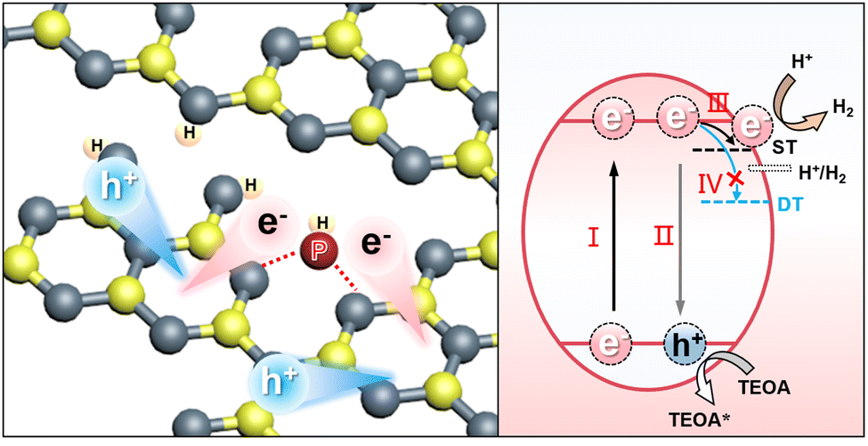 | ||
| Fig. 7 Photocatalytic H2 generation mechanisms over the Pi-Ho@C3−xC3−xN4: (Step I) visible-light excitation and electron–hole separation; (Step II) electron–hole recombination; (Step III) electron-trapping by shallow trap state (ST); (Step IV) electron-trapping by deep trap state (DT). | ||
Conclusions
In summary, a highly efficient g-C3−xN4-based photocatalyst has been designed and synthesized to incorporate strong synergistic effects of mesoporosity and phosphorous interstitial doping. Moreover, the in situ proton-assisted phosphorus interstitial bridge enhances shallow charge trapping in holey g-C3−xN4. The resulting Pi-Ho@C3−xN4 photocatalyst greatly enhances the photodynamics of visible-light-driven H2 production. Pore-enriched g-C3N4 directly improves the redox capacity for the photocatalytic water reduction with more exposed catalytic sites and carbon vacancies. Importantly, the phosphorus interstitial doping provides a new charge migration channel (–N–PN–), still with a robust driving force to guarantee highly efficient spatial separation of the charge carriers and long-lived active intermediates. Theoretical simulation and in situ transient absorption spectroscopy clearly show the long lifetime of the shallow-trapped charges and efficient kinetics in H-terminated catalysts. Proton-induced kinetics effectively promote the active species to participate in the photocatalytic reactions before being recombined. As a result, the as-prepared Pi-Ho@C3−xN4 photocatalyst shows an 8-fold enhancement in photocatalytic H2 production (6323 vs. 790 μmol h−1 g−1), and a 5.8-fold increase (5.08% vs. 0.87% at 420 nm) in quantum efficiency, compared with bulk g-C3N4. The proposed synergistic effect of water and interstitial P-doping offers a promising strategy for solar-to-hydrogen conversion with balanced redox capability and effective charge carrier separation.
Author contributions
W. Wang: investigation, formal analysis, data curation, and writing of the original draft. L. Du: investigation, data curation, and writing – review & editing. R. Xia: investigation. R. Liang: investigation and data curation. T. Zhou: investigation. Z. Yan: investigation. C. Shang: investigation and revision. H. Lee: investigation. D. L. Phillips: supervision, conceptualization, and writing – review & editing. Z. X. Guo: supervision, funding acquisition, conceptualization, project administration, and writing – review & editing. The manuscript was written by W. Wang, Z. Guo and D. L. Phillips with contributions from the other co-authors. All authors participated in the discussion of the research and have given approval to the final version of the manuscript.Conflicts of interest
There are no conflicts to declare.Acknowledgements
We gratefully acknowledge the following sponsorship and support from the Hong Kong UGC-TRS (T23-713/22-R) award, the Environment and Conservation Fund (ECF 2021-152), the RGC-EU Collaborative Programme initiative (E-HKU704/19), the RGC-GRF (17302419, 17316922), the Natural Science Foundation of Zhejiang Province (LY19E020008), the Key-Area Research and Development Program of Guangdong Province (2020B0101370003), the Joint Laboratory Funding Scheme (JLFS/P-704/18), the “Hong Kong Quantum AI Lab Ltd” funded by the AIR@InnoHK, launched by the Innovation and Technology Commission (ITC), and the URC Platform Technology Fund and the start-up support from the University of Hong Kong. Publication made possible in part by support from the HKU Libraries via. the Open Access Author Fund.Notes and references
- H. Nishiyama, T. Yamada, M. Nakabayashi, Y. Maehara, M. Yamaguchi, Y. Kuromiya, Y. Nagatsuma, H. Tokudome, S. Akiyama, T. Watanabe, R. Narushima, S. Okunaka, N. Shibata, T. Takata, T. Hisatomi and K. Domen, Nature, 2021, 598, 304–307 CrossRef CAS PubMed.
- L. Lin, Z. Lin, J. Zhang, X. Cai, W. Lin, Z. Yu and X. Wang, Nat. Catal., 2020, 3, 649–655 CrossRef CAS.
- Y. Zhang, J. Zhao, H. Wang, B. Xiao, W. Zhang, X. Zhao, T. Lv, M. Thangamuthu, J. Zhang, Y. Guo, J. Ma, L. Lin, J. Tang, R. Huang and Q. Liu, Nat. Commun., 2022, 13, 58 CrossRef CAS.
- C. Wang, H. Zhang, W. Luo, T. Sun and Y. Xu, Angew. Chem., Int. Ed., 2021, 60, 25381–25390 CrossRef CAS.
- B. Lin, G. Yang and L. Wang, Angew. Chem., Int. Ed., 2019, 58, 4587–4591 CrossRef CAS PubMed.
- A. Fujishima and K. Honda, Nature, 1972, 238, 37–38 CrossRef CAS.
- Q. Xu, L. Zhang, B. Cheng, J. Fan and J. Yu, Chem, 2020, 6, 1543–1559 CAS.
- L. Zhang, R. Long, Y. Zhang, D. Duan, Y. Xiong, Y. Zhang and Y. Bi, Angew. Chem., Int. Ed., 2020, 59, 6224–6229 CrossRef CAS.
- D. Zhu and Q. Zhou, Appl. Catal., B, 2021, 281, 119474 CrossRef CAS.
- Y. Wei, L. Chen, H. Chen, L. Cai, G. Tan, Y. Qiu, Q. Xiang, G. Chen, T.-C. Lau and M. Robert, Angew. Chem., Int. Ed., 2022, 61, e202116832 CAS.
- Y. Lin, W. Su, X. Wang, X. Fu and X. Wang, Angew. Chem., Int. Ed., 2020, 59, 20919–20923 CrossRef CAS PubMed.
- J. Xie, S. A. Shevlin, Q. Ruan, S. J. A. Moniz, Y. Liu, X. Liu, Y. Li, C. C. Lau, Z. X. Guo and J. Tang, Energy Environ. Sci., 2018, 11, 1617–1624 RSC.
- D. Kong, X. Han, J. Xie, Q. Ruan, C. D. Windle, S. Gadipelli, K. Shen, Z. Bai, Z. Guo and J. Tang, ACS Catal., 2019, 9, 7697–7707 CrossRef CAS PubMed.
- Y. Xu, T. F. Tay, L. Cui, J. Fan, C. Niu, D. Chen, Z. X. Guo, C. Sun, X. L. Zhang and R. A. Caruso, Inorg. Chem., 2020, 59, 17631–17637 CrossRef CAS PubMed.
- W. Wang, S. Zhu, Y. Cao, Y. Tao, X. Li, D. Pan, D. L. Phillips, D. Zhang, M. Chen, G. Li and H. Li, Adv. Funct. Mater., 2019, 29, 1901958 CrossRef.
- I. Grigioni, L. Ganzer, F. V. A. Camargo, B. Bozzini, G. Cerullo and E. Selli, ACS Energy Lett., 2019, 4, 2213–2219 CrossRef CAS.
- G.-J. Lai, L.-M. Lyu, Y.-S. Huang, G.-C. Lee, M.-P. Lu, T.-P. Perng, M.-Y. Lu and L.-J. Chen, Nano Energy, 2021, 81, 105608 CrossRef CAS.
- S. Chandrasekaran, D. Ma, Y. Ge, L. Deng, C. Bowen, J. Roscow, Y. Zhang, Z. Lin, R. D. K. Misra, J. Li, P. Zhang and H. Zhang, Nano Energy, 2020, 77, 105080 CrossRef CAS.
- C. Yang, R. Li, K. A. I. Zhang, W. Lin, K. Landfester and X. Wang, Nat. Commun., 2020, 11, 1239 CrossRef CAS PubMed.
- Y. Zheng, Y. Chen, B. Gao, B. Lin and X. Wang, Adv. Funct. Mater., 2020, 30, 2002021 CrossRef CAS.
- C. Hu, F. Chen, Y. Wang, N. Tian, T. Ma, Y. Zhang and H. Huang, Adv. Mater., 2021, 33, 2101751 CrossRef CAS PubMed.
- X. Chen, J. Wang, Y. Chai, Z. Zhang and Y. Zhu, Adv. Mater., 2021, 33, 2007479 CrossRef CAS PubMed.
- S. A. Shevlin and Z. X. Guo, Chem. Mater., 2016, 28, 7250–7256 CrossRef CAS.
- Q. Ruan, T. Miao, H. Wang and J. Tang, J. Am. Chem. Soc., 2020, 142, 2795–2802 CrossRef CAS PubMed.
- W. Wang, X. Bai, Q. Ci, L. Du, X. Ren and D. L. Phillips, Adv. Funct. Mater., 2021, 31, 2103978 CrossRef CAS.
- W. Wang, Y. Tao, L. Du, Z. Wei, Z. Yan, W. K. Chan, Z. Lian, R. Zhu, D. L. Phillips and G. Li, Appl. Catal., B, 2021, 282, 119568 CrossRef CAS.
- W. Wang, X. Zhao, Y. Cao, Z. Yan, R. Zhu, Y. Tao, X. Chen, D. Zhang, G. Li and D. L. Phillips, ACS Appl. Mater. Interfaces, 2019, 11, 16527–16537 CrossRef CAS PubMed.
- H. Wang, X. Sun, D. Li, X. Zhang, S. Chen, W. Shao, Y. Tian and Y. Xie, J. Am. Chem. Soc., 2017, 139, 2468–2473 CrossRef CAS PubMed.
- J. Wang, Y. Yu, J. Cui, X. Li, Y. Zhang, C. Wang, X. Yu and J. Ye, Appl. Catal., B, 2022, 301, 120814 CrossRef CAS.
- G. Liu, Y. Huang, H. Lv, H. Wang, Y. Zeng, M. Yuan, Q. Meng and C. Wang, Appl. Catal., B, 2021, 284, 119683 CrossRef CAS.
- L. Luo, Z. Gong, J. Ma, K. Wang, H. Zhu, K. Li, L. Xiong, X. Guo and J. Tang, Appl. Catal., B, 2021, 284, 119742 CrossRef CAS.
- W. Wang, H. Zhou, Y. Liu, S. Zhang, Y. Zhang, G. Wang, H. Zhang and H. Zhao, Small, 2020, 16, 1906880 CrossRef CAS PubMed.
- J. Fu, B. Zhu, C. Jiang, B. Cheng, W. You and J. Yu, Small, 2017, 13, 1603938 CrossRef PubMed.
- D. Zhao, Y. Wang, C.-L. Dong, Y.-C. Huang, J. Chen, F. Xue, S. Shen and L. Guo, Nat. Energy, 2021, 6, 388–397 CrossRef CAS.
- K. Kang, S. Watanabe, K. Broch, A. Sepe, A. Brown, I. Nasrallah, M. Nikolka, Z. Fei, M. Heeney, D. Matsumoto, K. Marumoto, H. Tanaka, S.-I. Kuroda and H. Sirringhaus, Nat. Mater., 2016, 15, 896–902 CrossRef CAS PubMed.
- X. Ma, Y. Lv, J. Xu, Y. Liu, R. Zhang and Y. Zhu, J. Phys. Chem. C, 2012, 116, 23485–23493 CrossRef CAS.
- L. F. Villalobos, M. T. Vahdat, M. Dakhchoune, Z. Nadizadeh, M. Mensi, E. Oveisi, D. Campi, N. Marzari and K. V. Agrawal, Sci. Adv., 2020, 6, eaay9851 CrossRef CAS PubMed.
- T. Palanisamy, S. Mitra, N. Batra, J. Smajic, A.-H. Emwas, I. Roqan and P. M. F. J. Costa, Adv. Mater. Interfaces, 2022, 9, 2200313 CrossRef CAS.
- H. Ou, C. Tang, X. Chen, M. Zhou and X. Wang, ACS Catal., 2019, 9, 2949–2955 CrossRef CAS.
- Y. Li, X. Liu, L. Tan, Z. Cui, X. Yang, Y. Zheng, K. W. K. Yeung, P. K. Chu and S. Wu, Adv. Funct. Mater., 2018, 28, 1800299 CrossRef.
- W. Xing, W. Tu, Z. Han, Y. Hu, Q. Meng and G. Chen, ACS Energy Lett., 2018, 3, 514–519 CrossRef CAS.
- Y. Li, R. Jin, Y. Xing, J. Li, S. Song, X. Liu, M. Li and R. Jin, Adv. Energy Mater., 2016, 6, 1601273 CrossRef.
- H. Yang, Y. Zhou, Y. Wang, S. Hu, B. Wang, Q. Liao, H. Li, J. Bao, G. Ge and S. Jia, J. Mater. Chem. A, 2018, 6, 16485–16494 RSC.
- X. Dang, R. Yang, Z. Wang, S. Wu and H. Zhao, J. Mater. Chem. A, 2020, 8, 22720–22727 RSC.
- W.-J. Ong, L.-L. Tan, Y. H. Ng, S.-T. Yong and S.-P. Chai, Chem. Rev., 2016, 116, 7159–7329 CrossRef CAS PubMed.
- J. Ran, T. Y. Ma, G. Gao, X.-W. Du and S. Z. Qiao, Energy Environ. Sci., 2015, 8, 3708–3717 RSC.
- S. Lv, Y. H. Ng, R. Zhu, S. Li, C. Wu, Y. Liu, Y. Zhang, L. Jing, J. Deng and H. Dai, Appl. Catal., B, 2021, 297, 120438 CrossRef CAS.
- S. Hu, L. Ma, J. You, F. Li, Z. Fan, F. Wang, D. Liu and J. Gui, RSC Adv., 2014, 4, 21657–21663 RSC.
- H. Che, C. Liu, G. Che, G. Liao, H. Dong, C. Li, N. Song and C. Li, Nano Energy, 2020, 67, 104273 CrossRef CAS.
- W. Luo, Y. Li, J. Wang, J. Liu, N. Zhang, M. Zhao, J. Wu, W. Zhou and L. Wang, Nano Energy, 2021, 87, 106168 CrossRef CAS.
- X.-N. Cao, S. Lian, Y. Tong, W. Lin, L. Jia, Y. Fang and X. Wang, Chem. Commun., 2020, 56, 916–919 RSC.
- C. Lu, L. Yang, B. Yan, L. Sun, P. Zhang, W. Zhang and Z. Sun, Adv. Funct. Mater., 2020, 30, 2000852 CrossRef CAS.
- M. Wu, J. Zhang, B.-B. He, H.-W. Wang, R. Wang and Y.-S. Gong, Appl. Catal., B, 2019, 241, 159–166 CrossRef CAS.
- H. Wang, S. Jiang, W. Liu, X. Zhang, Q. Zhang, Y. Luo and Y. Xie, Angew. Chem., Int. Ed., 2020, 59, 11093–11100 CrossRef CAS PubMed.
- Q. Li, P. Xu, B. Zhang, G. Wu, H. Zhao, E. Fu and H.-L. Wang, Nanoscale, 2013, 5, 7397–7402 RSC.
- L. Li, Q. Zhang, X. Wang, J. Zhang, H. Gu and W.-L. Dai, J. Phys. Chem. C, 2021, 125, 10964–10973 CrossRef CAS.
- W. Zhao, S. Wang, C. Wang, S. Wu, W. Xu, M. Zou, A. Ouyang, A. Cao and Y. Li, Nanoscale, 2016, 8, 626–633 RSC.
- S. Xiao, W. Dai, X. Liu, D. Pan, H. Zou, G. Li, G. Zhang, C. Su, D. Zhang, W. Chen and H. Li, Adv. Energy Mater., 2019, 9, 1900775 CrossRef.
- W. Wang, Y. Tao, J. Fan, Z. Yan, H. Shang, D. L. Phillips, M. Chen and G. Li, Adv. Funct. Mater., 2022, 32, 2201357 CrossRef CAS.
- H. Niu, W. Zhao, H. Lv, Y. Yang and Y. Cai, Chem. Eng. J., 2021, 411, 128400 CrossRef CAS.
- W. Wang, H. Zhang, S. Zhang, Y. Liu, G. Wang, C. Sun and H. Zhao, Angew. Chem., Int. Ed., 2019, 58, 16644–16650 CrossRef CAS PubMed.
- C. Yang, B. Wang, L. Zhang, L. Yin and X. Wang, Angew. Chem., Int. Ed., 2017, 56, 6627–6631 CrossRef CAS PubMed.
- P. Chen, X. A. Dong, M. Huang, K. Li, L. Xiao, J. Sheng, S. Chen, Y. Zhou and F. Dong, ACS Catal., 2022, 12, 4560–4570 CrossRef CAS.
- Z. Jiang, X. Zhang, H.-S. Chen, P. Yang and S. P. Jiang, Small, 2020, 16, 2003910 CrossRef CAS PubMed.
- W. Tu, Y. Xu, J. Wang, B. Zhang, T. Zhou, S. Yin, S. Wu, C. Li, Y. Huang, Y. Zhou, Z. Zou, J. Robertson, M. Kraft and R. Xu, ACS Sustainable Chem. Eng., 2017, 5, 7260–7268 CrossRef CAS.
- J. Xue, M. Fujitsuka and T. Majima, ACS Appl. Mater. Interfaces, 2019, 11, 40860–40867 CrossRef CAS PubMed.
- J. Fu, K. Liu, K. Jiang, H. Li, P. An, W. Li, N. Zhang, H. Li, X. Xu, H. Zhou, D. Tang, X. Wang, X. Qiu and M. Liu, Adv. Sci., 2019, 6, 1900796 CrossRef CAS PubMed.
- X. Liang, L. Shi, Y. Liu, H. Chen, R. Si, W. Yan, Q. Zhang, G.-D. Li, L. Yang and X. Zou, Angew. Chem., Int. Ed., 2019, 58, 7631–7635 CrossRef CAS PubMed.
- Y.-C. Chu, T.-J. Lin, Y.-R. Lin, W.-L. Chiu, B.-S. Nguyen and C. Hu, Carbon, 2020, 169, 338–348 CrossRef CAS.
- K. L. Corp and C. W. Schlenker, J. Am. Chem. Soc., 2017, 139, 7904–7912 CrossRef CAS PubMed.
- Z. Chen, Q. Zhang and Y. Luo, Angew. Chem., Int. Ed., 2018, 57, 5320–5324 CrossRef CAS PubMed.
- R. Godin, Y. Wang, M. A. Zwijnenburg, J. Tang and J. R. Durrant, J. Am. Chem. Soc., 2017, 139, 5216–5224 CrossRef CAS PubMed.
- Q. Ruan, M. K. Bayazit, V. Kiran, J. Xie, Y. Wang and J. Tang, Chem. Commun., 2019, 55, 7191–7194 RSC.
Footnote |
| † Electronic supplementary information (ESI) available: Details of experimental methods and calculation parameters; SEM and STEM images; EDX elements' linear distribution and XPS spectra; FTIR profiles; comparison of photocatalytic H2 production activity; Tafel plots; the fs-TAS and ns-TAS setup; exponential function fitted parameters of fs-TAS and ns-TAS; and calculated DOS and formation energy. See DOI: https://doi.org/10.1039/d2ee02680e |
| This journal is © The Royal Society of Chemistry 2023 |