
 Open Access Article
 This Open Access Article is licensed under a Creative Commons Attribution-Non Commercial 3.0 Unported Licence
Structural dynamics of a thermally silent triiron(II) spin crossover defect grid complex†
Jose de Jesus
Velazquez-Garcia
 *a,
Krishnayan
Basuroy
a,
Darina
Storozhuk
a,
Joanne
Wong
b,
Serhiy
Demeshko
b,
Franc
Meyer
b,
Robert
Henning
c and
Simone
Techert
*ad
*a,
Krishnayan
Basuroy
a,
Darina
Storozhuk
a,
Joanne
Wong
b,
Serhiy
Demeshko
b,
Franc
Meyer
b,
Robert
Henning
c and
Simone
Techert
*ad
aDeutsches Elektronen-Synchrotron DESY, Notkestr. 85, 22607 Hamburg, Germany. E-mail: jose.velazquez@desy.de; simone.techert@desy.de
bInstitut für Anorganische Chemie, Georg-August-Universität Göttingen, Tammannstraße, 4, 37077, Göttingen, Germany
cCenter for Advanced Radiation Sources, The University of Chicago, Argonne National Laboratory, 9700 South Cass Ave, Lemont, Illinois 90439, USA
dInstitut für Röntgenphysik, Georg-August-Universität Göttingen, Friedrich-Hund-Platz 1, Göttingen, 37077, Germany
First published on 1st September 2023
Abstract
The structural evolution of spin crossover (SCO) complexes during their spin transition at equilibrium and out-of-equilibrium conditions needs to be understood to enable their successful utilisation in displays, actuators and memory components. In this study, diffraction techniques were employed to study the structural changes accompanying the temperature increase and the light irradiation of a defect [2 × 2] triiron(II) metallogrid of the form [FeII3LH2(HLH)2](BF4)4·4MeCN (FE3), LH = 3,5-bis{6-(2,2′-bipyridyl)}pyrazole. Although a multi-temperature crystallographic investigation on single crystals evidenced that the compound does not exhibit a thermal spin transition, the structural analysis of the defect grid suggests that the flexibility of the grid, provided by a metal-devoid vertex, leads to interesting characteristics that can be used for intermolecular cooperativity in related thermally responsive systems. Time-resolved photocrystallography results reveal that upon excitation with a ps laser pulse, the defect grid shows the first two steps of the out-of-equilibrium process, namely the photoinduced and elastic steps, occurring at the ps and ns time scales, respectively. Similar to a previously reported [2 × 2] tetrairon(II) metallogrid, FE3 exhibits a local distortion of the entire grid during the photoinduced step and a long-range distortion of the lattice during the elastic step. Although the lifetime of the pure photoinduced high spin (HS) state is longer in the tetranuclear grid than in the defect grid, suggesting that the global nuclearity plays a crucial role for the lifetime of the photoinduced species, the influence of the co-crystalising solvent on the lifetime of the photoinduced HS state remains unknown. This study sheds light on the out-of-equilibrium dynamics of a thermally silent defect triiron SCO metallogrid.
Introduction
Spin crossover (SCO) complexes are switchable molecules capable of reversibly changing their spin state from a low-spin (LS) to a high-spin (HS) state under the influence of various external stimuli, such as temperature, pressure, electric field or light.1–5 Most of the vast number of SCO compounds are mononuclear, FeII-centered complexes where the LS state corresponds to S = 0 (t2g6eg0 configuration, singlet) and the HS state to S = 2 (t2g4eg2, quintet).6–9 However, recent progress in supramolecular chemistry has allowed for the synthesis of a variety of discrete polynuclear SCO FeII complexes.10,11 [2 × 2] FeII4 metallogrids are an example of the latter type of complexes, in which four metal ions and four ditopic ligand strands give a matrix-like structure with up to four potentially addressable sites arranged in a square.12–17 This type of complex is appealing because it offers the potential for intramolecular cooperativity through the strong linking of the metal centres, which can be used in molecular logic devices, such as nanoscale memory devices and quantum automata, among others.18In a series of publications, some of us have reported a family of metallogrid complexes with the general formula [FeXLR4], where X = 2,3,4, L = R-3,5-bis{6-(2,2′-bipyridyl)}pyrazolate and R = H, methyl.19–22 This rational design approach has allowed for the customisation of various SCO properties, such as transition temperature, number of SCO steps and cooperative behaviour. For instance, the parent complex [Fe4LH4](BF4)4·MeCN (1) undergoes a incomplete multistep thermal transition from [4HS] to [2LS–2HS] in the 300K to 50K range. By introducing a methyl substituent to the C4 position of the pyrazolate ring, a metallogrid complex [Fe4LMe4](BF4)4·2MeCN (FE4) was obtained. The stronger ligand field in FE4 stabilises the LS fraction, resulting in a di-mixed-spin configuration [HS–LS–HS–LS] over a wider temperature range, from 7 to 250 K. Above 250 K, the complex undergoes a single gradual SCO and a change of configuration to [1LS–3HS]. Furthermore, the removal of one metal centre in 1 leads to the formation of a trinuclear FeII grid, also known as ‘defect grid’, of the form [FeII3LH2(HLH)2](BF4)4·4MeCN (FE3), as shown in Fig. 1. The defect grid has the unique combination of strongly elastically coupled metal ions and a structurally soft metal-devoid vertex, which gives rise to a cooperative transition from [2LS–1HS] to [1LS–2HS] upon loss of the lattice solvent. Although this spin transition of FE3 at equilibrium conditions has been reported previously,22 there is no information about the out-of-equilibrium dynamics of this grid.
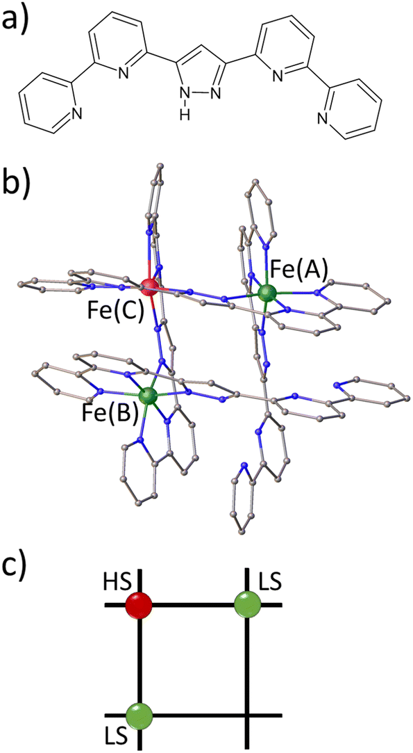 | ||
| Fig. 1 (a) Pyrazole-bridged compartmental ligand HL. (b) Molecular representation of the [Fe3L4]4+ grid. Fe(A)and Fe(B) ions are in the LS state, and Fe(C) ions are in the HS state. Counter ions, solvent molecules and hydrogen atoms are omitted for clarity. (c) Schematic representation of the grid in FE3. | ||
The presence of solvent molecules in the lattice of the SCO complexes has varying effects on the spin transition. Previous studies have demonstrated that small solvent molecules can induce,23,24 alter25,26 or suppress27–31 the thermal spin transition of SCO complexes. Although some reports have demonstrated a photoinduced transition following light irradiation at low temperatures in iron complexes, where thermal spin transition is assisted by the desolvation process,29,30 there is no clear understanding of the effects of the solvent in the photoinduced spin transition or the out-of-equilibrium dynamics of such complexes.
In response to a fs laser pulse, crystals of mononuclear SCO compounds exhibit complex out-of-equilibrium dynamics involving three consecutive steps: photoinduced, elastic and thermal steps, occurring at characteristic time-scales of picoseconds (ps), nanoseconds (ns) and microseconds (μs), respectively.32–36 The initial photoinduced step involves local conversion from LS to HS states via intersystem crossing through metal-to-ligand charge transfer (MLCT) excitation; this photo-switching process is proportional to the density of laser excitation, where one photon switches one metal centre from the LS to the HS state, accompanied by a structural reorganisation at the molecular scale. The second step, known as the ‘elastic step’, is associated with an additional conversion to the HS state and the volume expansion of the lattice at the material scale, which is not instantaneous and requires propagation of strain waves37 at the speed of sound (∼2000 ms−1). Finally, the third step, referred to as the thermal step, occurs on the μs time scale when the average temperature of the crystal increases due to heat diffusion.
In our previous works,38,39 we employed time-resolved photocrystallography to investigate the out-of-equilibrium dynamics of FE4. Our findings revealed that the out-of-equilibrium dynamics triggered by a ps laser pulse follow the same sequence as observed in mononuclear SCO complexes. However, unlike mononuclear complexes, FE4 exhibits two distinct types of elastic distortions occurring at different time scales. The first type is a short-range distortion, observed during the ps time scale, that propagates over the entire Fe4 grid complex. This distortion results from the rearrangement of the coordination sphere of the photo-switching ion and the constant feedback between strongly linked metal ions. The second type takes place during the ns time scale and is a long-range distortion caused by the anisotropic expansion of the lattice, which is commonly observed in the dynamics of mononuclear SCO materials. The structural analysis of FE4 demonstrated that the long-range distortion prevails over the short-range distortion, leading to the largest deformation of both the entire grid and the coordination sphere of each metal ion in the ns time scale.
However, the aforementioned studies do not provide information on the out-of-equilibrium dynamics of SCO complexes, where the solvent silences the thermal SCO, or in SCO defect grids. Therefore, this work aims to investigate the out-of-equilibrium structural dynamics of the thermally silent FE3. Since the structure of FE3 at 133 K, as well as the magnetic properties and physicochemical characterisation, have been reported in a previous publication,22 this work focuses on exploring its out-of-equilibrium structural dynamics during the first 1 ns after light excitation, as well as the structural changes upon heating the grid from 100 K to 310 K. The multi-temperature structural analysis reveals that while FE3 lacks a thermal spin transition, the flexibility of the grid, facilitated by a metal-devoid vertex, offers intriguing characteristics that may support intermolecular cooperativity in other thermally responsive systems. More interestingly, we show that upon excitation, FE3 presents the first two steps of the out-of-equilibrium process, as well as the two types of elastic distortions observed in FE4. A comparison between the FE3 and FE4 grids demonstrates that the photo-switched HS state relaxes more rapidly in FE3 than in FE4.
Methods
Synthesis and steady-state spectroscopy
The FE3 metallogrid and its ligands were synthesised following the procedure reported in the literature.22UV-vis spectra were collected at room temperature on a Varian Cary-5E UV-vis Spectrometer. All data were collected at a scan rate of 0.2 nm s−1 over the wavelength range of 200–800 nm with an interval size of 0.5 nm. The absorption spectrum of FE3 was collected on 10 mm cuvettes, using a reference spectrum of acetonitrile, which was also used to dissolve the compound.
X-ray diffraction
Single-crystal X-ray diffraction experiments were performed from 100 K to 310 K (the maximum temperature possible before crystal decay became unacceptable). The X-ray data were collected in phi scan mode on undulator synchrotron radiation with λ = 0.6199 Å at P11 beamline in PETRA III, DESY, Hamburg, Germany. Indexing of the X-ray diffraction pattern, unit cell refinement and spot integration were performed using the XDS program package.40 The crystal structures were solved with the SHELXT41 structure solution program within the Olex2 software package.42 Subsequently, the structures were refined against F2 isotropically, followed by full matrix anisotropic least squares refinement by SHELXL.43 For all structures, hydrogen atoms were fixed geometrically, in idealised positions, and allowed to ride with the respective C or N atoms, to which each was bonded, in the final cycle of refinement. Crystal data and structure refinement parameters for the 100 K dataset are provided in Table S1,† while the selected bond lengths and bond angles are given in Table S2.† The asymmetric unit cell, thermal ellipsoid plot and packing of molecules down all crystallographic axes at 100 K are given in Fig. S1–S5.Time-resolved pink Laue crystallography
Time-resolved X-ray diffraction (TRXRD) measurements were performed at the BioCARS beamline at the Advanced Photon Source, Argonne National Laboratory, IL, USA. TRXRD data were collected at 15KeV with a Rayonix MX340-HS detector. Pulses from a Ti:sapphire laser tuned to 390 nm wavelength were used as a pump source and set perpendicular to the φ-rotation axis. The time delay between the laser pump and the X-ray probe was set by varying the arrival times of the picosecond laser pulses with respect to the synchrotron X-ray pulses. Delay times (dt) between the laser pump and the X-ray probe were selected at 200 ps, 500 ps, 700 ps and 1 ns. A reference measurement for each crystal was taken at the negative delay time (dt < 0) of −500 ps. Laser power was set at 2.0 (mJ mm−2) per pulse. Crystallographic data were acquired at 100 K since the lifetime of the locally excited molecules is larger at low temperatures. The latter temperature was limited by the equipment capability. The recorded data sets for each crystal covered a 180° scan with 1° step.Since crystals of FE3 showed a fast decay under laser exposure, a typical data collection strategy of 5 laser-OFF/ON cycle used in our previous works38,39,44 was not recommended. Therefore, a strategy of one laser-ON at dt < 0 followed by all laser-ON at dt was used for each crystal. The measurement was repeated in five different crystals for each compound. Crystals used in this study had approximate dimensions of 90 × 50 × 30 μm3.
The pink Laue diffraction images were processed with the software package Precognition/Epinorm,45 using variable elliptical integration for all data sets. After integration, the dt and dt < 0 data sets were scaled together, but the repetitive and symmetry-related reflections from both data sets were merged separately. These data sets were used to obtain the photodifference maps and the final structural models at each delay time. For all data sets, initial models of the crystal structures were taken from those obtained from the monochromatic X-ray diffraction experiment at 100 K. Subsequently, the structures were refined using the SHELXL program within the Olex2 software package. Thermal ellipsoid plots (50% of probability) for all time-resolved data sets are provided in ESI (Fig. S6–S10).†
Modification of the coordination environment
The Octadist46 program was used to characterise the coordination geometry of the metal ions in each compound, in particular the 〈Fe–N〉 bond length distance and the angular distortion parameter (Θ). The angular distortion parameter is the sum of the deviations from 60° of the 24 N–Fe–N angles, six per pseudo three-fold axis, measured on a projection of opposite triangular faces of the FeN6 octahedron, orientated by superimposing the face centroids [see Fig. S11†]. For comparison, continuous symmetry measurements47 calculated using the SHAPE program48 were also used to characterise the change in symmetry and shape of the metal coordination sphere. The calculation of S(Oh) and S(itp), which compare the coordination sphere with respect to a perfect octahedron and trigonal prism, respectively, were done for all crystallographically independent metal ions from structures at 100 K, 250 K and 310 K (see ESI† for more information). Both Θ and S(Oh) parameters are small and closer to 0 when the metal centre is in LS state, while S(itp) ≫ 0, and the opposite is shown for metal centres in HS state.Analysis of temperature increase due to laser exposure
An estimate of the temperature change between the dt and dt < 0 data sets was obtained from the well-known photo-Wilson plots.49,50 The plots for all time-resolved data are shown in Fig. S13.† The slope of the plot corresponds to twice the difference of the Debye–Waller factor (2ΔBdt−dt<0), associated with the isotropic atomic motion (for more information see the temperature difference section in ESI†). Therefore, measuring ΔB between the dt and dt < 0 data sets provides an estimate of the temperature increase due to laser exposure through the associated increase in thermal motion. Values of ΔBdt−dt<0 ≈ 0 indicate a non-detectable global heating of the sample, while values greater than zero suggest an increase in temperature of the crystal.Results
Multi-temperature structural analysis
Table 1 provides the geometrical characteristics of the FeN6 octahedra in FE3 at both 100 K and 310 K. A more detailed structural description of the compound is provided in Table S3.† The structural analysis confirms that the FE3 defect grid maintains its P![[1 with combining macron]](https://www.rsc.org/images/entities/char_0031_0304.gif) space group across the temperature range. At both temperatures, four acetonitrile molecules were observed cocrystallising in the lattice, from which two were refined as disordered over two positions (Fig. S1†). As reported in the literature,22 the asymmetric unit of the compound reveals that all metal ions are crystallographically independent with a molecular configuration of [LS–HS–LS], which was deduced from analysing the coordination sphere of each metal ion (and in accordance with the results of 57Fe Mössbauer spectroscopy22). The analysis of the coordination geometry demonstrates that LS and HS ions exhibit typical values of 〈Fe–N〉 bond lengths, with LS atoms between 1.95 and 1.97 Å and HS atoms around 2.18 Å. A further difference between the metal centres is the distortion of the {FeN6} coordination environment from an ideal octahedron. The less distorted FeN6 octahedron is found for the LS ions, Fe(A) and Fe(B) with Θ = 301–314°, S(Oh) = 2.1–2.3, while the HS ion, Fe(C), displays a greater distortion of the coordination sphere with Θ = 570° and S(Oh) = 6.0.
space group across the temperature range. At both temperatures, four acetonitrile molecules were observed cocrystallising in the lattice, from which two were refined as disordered over two positions (Fig. S1†). As reported in the literature,22 the asymmetric unit of the compound reveals that all metal ions are crystallographically independent with a molecular configuration of [LS–HS–LS], which was deduced from analysing the coordination sphere of each metal ion (and in accordance with the results of 57Fe Mössbauer spectroscopy22). The analysis of the coordination geometry demonstrates that LS and HS ions exhibit typical values of 〈Fe–N〉 bond lengths, with LS atoms between 1.95 and 1.97 Å and HS atoms around 2.18 Å. A further difference between the metal centres is the distortion of the {FeN6} coordination environment from an ideal octahedron. The less distorted FeN6 octahedron is found for the LS ions, Fe(A) and Fe(B) with Θ = 301–314°, S(Oh) = 2.1–2.3, while the HS ion, Fe(C), displays a greater distortion of the coordination sphere with Θ = 570° and S(Oh) = 6.0.
| Metal | 100 K | 310 K | ||||
|---|---|---|---|---|---|---|
| 〈Fe–N〉 (Å) | Θ (°) | S(Oh) | 〈Fe–N〉 (Å) | Θ (°) | S(Oh) | |
| Fe(A) | 1.966 | 306.1 | 2.256 | 1.974 | 313.5 | 2.332 |
| Fe(B) | 1.959 | 301.9 | 2.183 | 1.968 | 310.5 | 2.284 |
| Fe(C) | 2.183 | 577.3 | 6.140 | 2.188 | 575.7 | 6.160 |
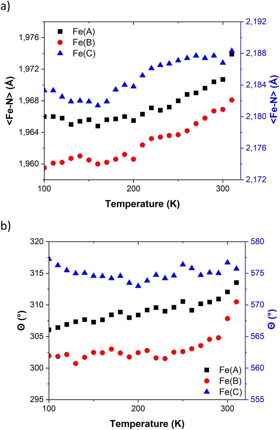 | ||
| Fig. 2 Temperature dependence of (a) 〈Fe–N〉 bond length distances and (b) angular distortions (Θ) in FE3. Values for Fe(A) and Fe(B) share the same axis. | ||
The temperature dependence of Θ (Fig. 2b) indicates that below 270 K there is no notable change in distortion of the {FeN6} octahedrons as the temperature increases. However, following the solvent loss and a potential small LS → HS transition, a slight change in the angular distortion of the Fe(A) and Fe(B) ions is observed. Notably, the Fe(B) ion exhibits a comparatively larger change in Θ, suggesting that it may undergo the most significant distortion during the spin transition.
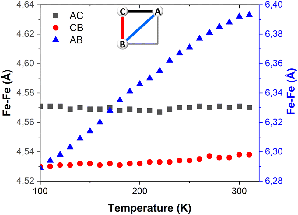 | ||
| Fig. 3 Temperature dependence of the Fe–Fe distances in FE3. Distances AC and CD share the same axis. | ||
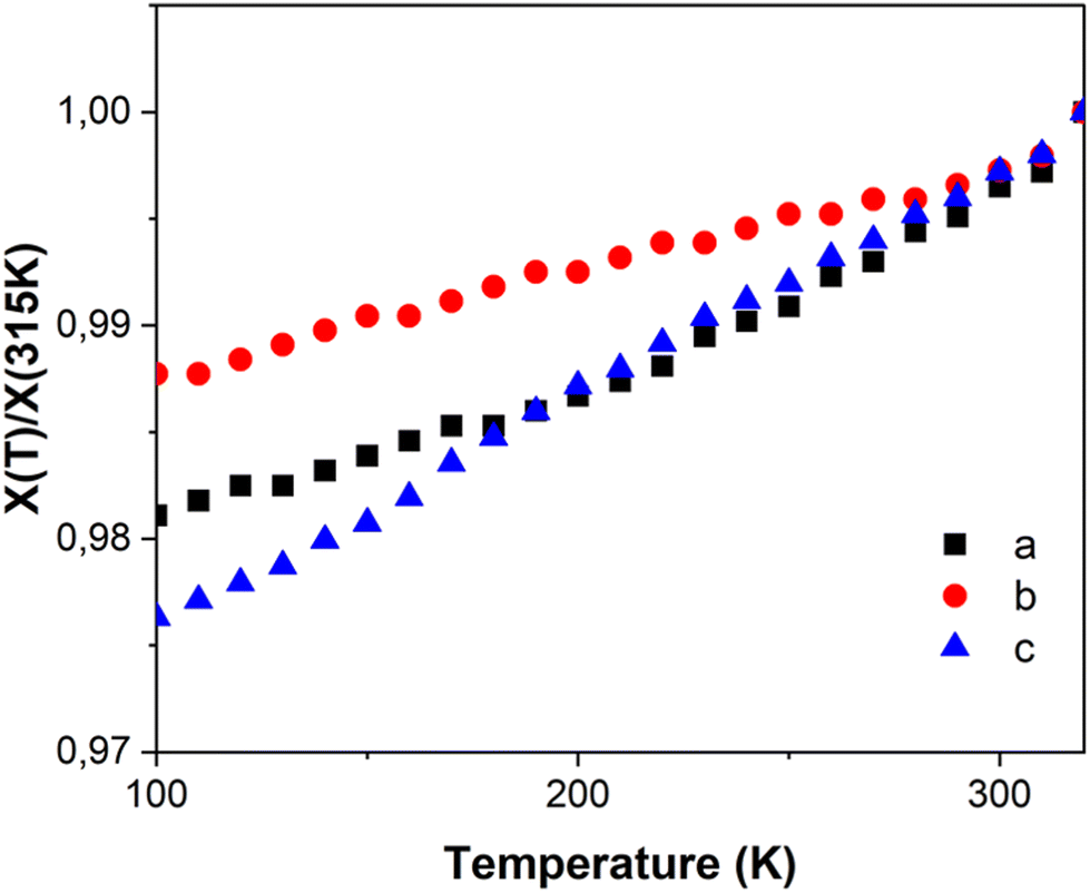 | ||
| Fig. 4 Relative temperature dependence of unit cell parameters of FE3. | ||
Out-of-equilibrium process
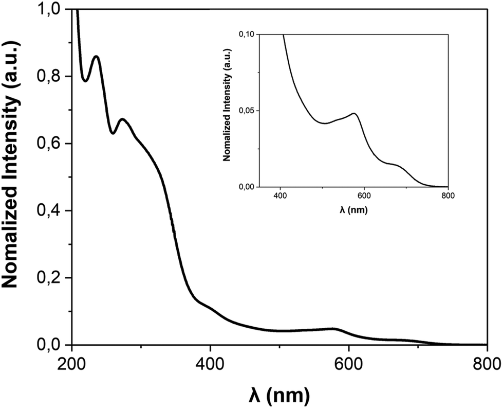 | ||
| Fig. 5 UV-vis spectrum of FE3 grid in acetonitrile. (inset) Enlargement of the 350–800 nm range. | ||
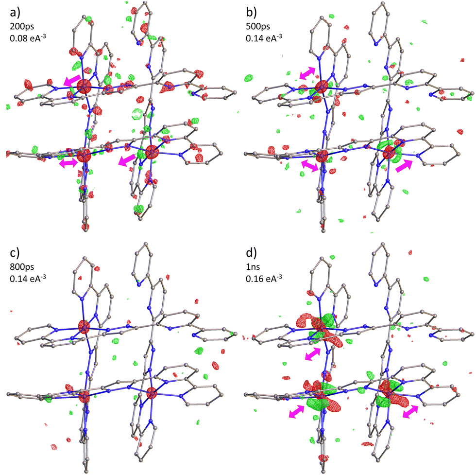 | ||
| Fig. 6 Photodifference maps of FE3 during (a–c) the photoinduced step and (d) the elastic step. Isosurfaces (green positive, red negative) and delay times are shown in each figure. Arrows give an approximate direction of the electron density shift. | ||
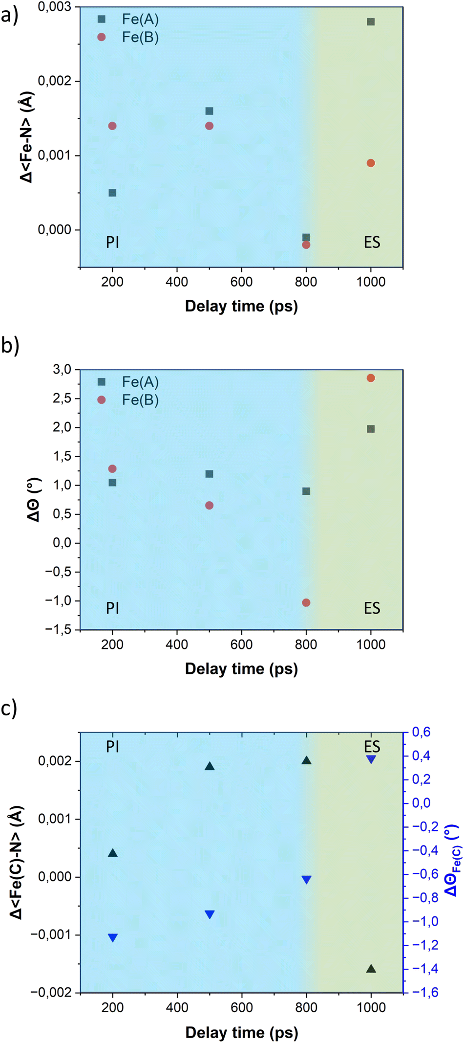 | ||
| Fig. 7 Time-delay dependence of (a) Δ〈Fe–N〉; (b) ΔΘ of the Fe(A) and Fe(B) ions; and (c) those from the Fe(C) ion. Photoinduced (PI) and elastic (ES) steps are shown in blue and green background, respectively. | ||
Although the elongation of the 〈Fe–N〉 bond lengths in both ions, which originally are in the LS state, may suggest a transition of the entire grid from a 2LS–1HS to a 3HS configuration, we consider an alternative scenario more likely where only one metal ion in the LS state switches to the HS state. If Fe(A) and Fe(B) ions have a similar probability to transit to a HS state upon excitation, the change in configuration from 2LS–1HS to 1LS–2HS in the crystal would result in a mixture of molecules with only Fe(A) or Fe(B) as the transition ion. Since crystallography provides an average representation of all molecules in the crystal, the expansion of the 〈Fe–N〉 bond lengths will be observed in both ions in the asymmetric unit, regardless of whether the structural changes belong to different molecules.
The variation of the trigonal distortion parameter in the time domain for the transiting metal ions Fe(A) and Fe(B) is shown in Fig. 7b. The figure reveals a slight increase in the distortion of the coordination sphere of both transiting metal ions during the photoinduced step. Notably, the Fe(B) ions exhibit a more pronounced distortion, consistent with the observations from the multi-temperature study. As observed in our previous studies on the FE4 grid, the distortion of the coordination spheres of both transiting atoms are larger during the elastic step than in the photoinduced step, as observed in the value of ΔΘ at 1 ns delay time.
Similar to the observations for the FE4 grid, the photoswitching at the Fe(A) and Fe(B) ions of the FE3 grid leads to changes in the coordination sphere of the adjacent metal ion in the HS state, Fe(C). Fig. 7c displays the expansion of the 〈Fe–N〉 bond length of Fe(C) ion and the concomitant change in the distortion of its coordination geometry following light irradiation. However, it should be noted that the changes are not related to any spin transition since the Fe(C) ion remains in the HS state throughout the experiment. Instead, these changes in its coordination sphere are attributed to a knock-on effect from the structural reorganisation of the whole grid following the spin transition in the neighbouring ions.
 | (1) |
 | (2) |
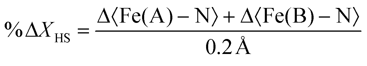
Table 2 presents the change in the HS-state molecular fraction from 200 ps to 1 ns, calculated from the expansion of the 〈Fe–N〉 bond length of the Fe(A) and Fe(B) ions. The estimated population of the excited state during the photoinduced step (dt < 800 ps) is in the 1–1.5% range, while ∼2% is estimated for the delay time in the elastic step (dt > 800 ps). The change in %ΔXHS is slightly larger in the elastic step than in the photoinduced step as typically reported in monometallic materials, where photoconversion of the elastic and thermal steps tends to overcome the photoinduced step.32 At 800 ps, most of the molecules relax to their ground state shown by the low value of the %ΔXHS and in agreement with the photodifference maps.
| 200 ps | 500 ps | 800 ps | 1 ns | |
|---|---|---|---|---|
| %ΔXHS | 1.0 (13) | 1.5 (13) | −0.2 (12) | 1.9 (13) |
| ΔBdt−dt<0 | 0.00 (6) | 0.07 (3) | 0.00 (2) | 0.06 (3) |
In the studied range of time, the LS → HS transition occurs without any significant energy exchange with the environment, as observed in the time-delay dependence of the isotropic thermal factor, ΔBdt−dt<0. Table 2 shows that the values of ΔBdt−dt<0 are close to zero and comparable with those reported for the FE4 grid in the photoinduced step and beginning of the elastic step. This suggests that heating of the crystal is not detectable within the measured range and that the two increases in the %![[thin space (1/6-em)]](https://www.rsc.org/images/entities/char_2009.gif) ΔXHS, one before and one after 800 ps, are solely attributed to the photoinduced step and elastic step, respectively.
ΔXHS, one before and one after 800 ps, are solely attributed to the photoinduced step and elastic step, respectively.
Discussion
One of the most ambitious goals of synthetic chemists in the SCO field is the rational design of SCO systems with tailored properties. With the aim of enhancing the SCO properties, e.g. abrupt, hysteretic and multistep switching, the design of SCO complexes has explored various strategies, including varying the number of metal centres (ranging from mononuclear to polymeric) and adopting diverse geometries, such as squares, cages and grids. One potential approach has been the utilisation of [2 × 2] grids formed by highly constrained ligands, which promote the communication between metal centres. Tetranuclear grids are rigid molecules, which restricts the overall movement of the architecture in favour of the communication between the linked metal centres. While such communication may lead to intramolecular cooperativity,56 there is no clear evidence suggesting that [2 × 2] grid-like arrangements promote intermolecular cooperativity. However, defect metallogrids with a metal-devoid flexible vertex may present a solution to this problem.The present multi-temperature crystallographic analysis sheds light on two interesting characteristics of such defect grids. Firstly, the FE3 defect grid displays a larger thermal expansion in its geometrical dimension compared to the more constrained FE4 grid, primarily due to the reduced restrain provided by the metal-devoid site. Secondly, the rotation of the pyridyl rings at this site offers a potential avenue for introducing long-range elastic interaction capable of modifying the unit cell expansion, as observed in other compounds.55 Although FE3 does not exhibit thermal SCO, these two characteristics of defect grids hold promise for promoting intermolecular cooperativity in other thermally responsive SCO grids. Thus, defect grids with one metal-devoid vertex and communicating metal ions may present an alternative strategy to enhance both the intermolecular cooperativity, by increasing the flexibility of the grid, and intramolecular cooperativity, provided by the strong linking of the metal ions. However, it is indispensable to consider other factors that can affect the SCO and the cooperativity, such as the lattice type, counter ions and solvent effects.
Solvent silencing is a well-known phenomenon that occurs in SCO complexes where the solvent delays the spin transition to higher temperatures or prevents it from happening. Numerous SCO complexes, including the FE3 grid, have been reported to be silenced by the presence of a specific solvent molecule within the crystal lattice.22,27–31 However, the out-of-equilibrium dynamics in this type of complexes remains largely unexplored. In this study, we observed that while the solvent supresses the thermal-induced SCO in FE3, two out of the three consecutive steps of the out-of-equilibrium process are observed following light irradiation.
In line with the observation in mononuclear FeII and FeIII complexes, as well as in the tetranuclear FE4 grid, excitation of the FE3 grid with a ps laser pulse initiates a multistep process, with each step occurring at distinct time scales.32–36 First, the light absorption leads to a local LS → HS transition in a fraction of molecules, resulting in the conversion of one of the FeII ions from the LS to the HS state. The spin flip is accompanied by the reorganisation of the {FeN6} coordination sphere of the transiting ion, which triggers a short-range elastic distortion that propagates through the grid due to the tightly linked metal ions. This distortion develops within the first few hundreds of picoseconds after light irradiation, and it is evidenced by the distinct shift in electron density observed in the photodifference maps at 200 ps and 500 ps. Notably, this molecular reorganisation resembles the behaviour observed in the FE4 grid, reinforcing the idea that the strong linking of metal ions leads to an elastic metal-to-metal communication during the spin transition. Subsequently, the elastic step takes place when the lattice heating, resulting from the energy dissipation, induces the coherent propagation of strain waves. This leads to lattice expansion and crystal deformation at the material scale, causing all metallic ions to move in the direction of the propagating strain waves, as observed in the photodifference maps at 1 ns. The internal pressure generated at this step leads to the second LS → HS switching, as reported in Table 2. Although the dynamics beyond 1 ns are not reported in this study, this second step typically lasts until the beginning of the μs time scale, after which it is followed by the thermal step when the energy distribution reaches a global temperature rise on the crystal. However, since the FE3 grid is thermally silent, this step is expected not to be present. Although the suppression of the thermal step in the out-of-equilibrium dynamics of FE3 could be perceived as a limitation, it provides valuable insights about the tailoring of the response of the SCO materials upon light excitation. Given that the spin switching during the elastic and thermal steps usually prevails over the pure photoinduced spin flip,32 the knowledge of how to limit these steps by chemical engineering is a valuable resource.
Comparing the lifetime of the photoinduced HS state in the FE3 defect grid with that observed in the FE4 grid suggests that the metastable HS state resulting from pure photo-switching exhibits a longer lifetime in FE4 than in FE3. While our previous report39 indicated that the photoinduced step in FE4 lasts approximately 800 ps, similar to FE3, those studies were conducted at a significantly higher temperature of 220 K, compared to 100 K used in this work. As the lifetime of the metastable states is known to be longer at lower temperatures, the duration of the photoinduced HS state in the FE4 at 100 K is estimated to be considerably longer than 800 ps (>2 ns), as suggested by our first studies on the FE4 grid.38 This observation aligns with time-resolved X-ray spectroscopic studies performed in solution, where the parent grid 1 exhibited a longer lifetime of the photoexcited state (∼210 ns) compared to the FE3 grid (∼123 ns).57,58 Thus, the results here reinforce the idea that global nuclearity of the architecture plays a pivotal role in tailoring the lifetime of the photoinduced species. However, it is important to consider that the presence of the solvent in both grids may also influence the lifetime of the pure photoinduced HS state, and therefore, more research is needed to understand its influence.
It is worth noting that the present study has been limited to a few data points within the first nanosecond after laser irradiation of a defect grid, whose thermal transition from a 2LS–1HS to a 1LS–2HS state is silenced by the presence of the co-crystallising acetonitrile solvent. Further investigations are necessary to obtain a detailed picture of the structural changes over extended timescales ranging from picoseconds to microseconds. Additionally, studies in a solvent-free grid and with other solvents would provide valuable information about the influence of the solvent on the lifetime of the metastable state and the structural changes occurring in each step of the out-of-equilibrium dynamics. This also helps to differentiate between the effects of the solvent and the metal-devoid site in the grid. A comprehensive analysis of all factors influencing the out-of-equilibrium dynamics of oligomeric SCO complexes would provide crucial insights for designing new SCO materials with tailored properties.
Conclusions
The rational design of spin crossover systems with diverse nuclearity and topology has emerged as a powerful approach to enhance cooperative effects and expand the variety of SCO properties, considering their potential application in nanoscale memory devices and quantum automata, among others. To effectively engineer SCO materials with tailored properties, it is crucial to develop a comprehensive understanding of factors influencing the spin transition in solid state, both at equilibrium and out-of-equilibrium conditions. Some significant factors include the number and arrangement of metal centres as well as the presence of solvent within the crystal lattice. In this study, we presented the structural analysis of a defect [2 × 2] metallogrid with one metal-devoid vertex, where the co-crystallising solvent silenced the thermal spin transition while allowing for the photoinduced transition at out-of-equilibrium conditions.Although the studied system FE3 does not exhibit thermal SCO, its structural flexibility, facilitated by the metal-devoid site, imparts attractive characteristics that can potentially favour the SCO in related systems, that is the large thermal expansion of the overall structure and rotation of the pyridyl rings at the metal-devoid site. These features are attractive for introducing long-range elastic interactions that can favour intermolecular cooperativity in other defect grids whose SCO is not affected by the solvent. Despite the solvent induced silencing of the thermal SCO transition, FE3 undergoes two of the three steps of the out-of-equilibrium process. Upon irradiation with a ps laser pulse, the FE3 defect grid exhibits the photoinduced and elastic steps occurring at ps and ns time scales, respectively. Each step introduces an increase in the fraction of the HS state and a different reorganisation. The structural reorganisation of FE3 during the out-of-equilibrium process is similar to that of the previously reported FE4 grid, involving a short-range distortion appearing from the continuous molecular rearrangement of the grid during the photoinduced step, triggered by LS → HS photo-switching of only one metal ion, and a long-range distortion caused by the anisotropic deformation of the lattice during the elastic step.
Compared to FE4, the pure photoinduced HS state in FE3 relaxes back to its original LS state in ∼800 ps at 100 K, while in FE4, it takes longer than 2 ns at 100 K and ∼800 ps at 220 K. This observation supports previous time-resolved X-ray spectroscopic findings in solution and suggests that global nuclearity plays a crucial role in the lifetime of the photoinduced species. However, the influence of the co-crystalising solvent on the lifetime of the photoinduced HS state remains unknown and requires further research with other solvents and solvent-free grids. Understanding the solvent effect at each step of the out-of-equilibrium process is essential for controlling the properties of SCO materials with bi- and multi-stability at equilibrium and out-of-equilibrium conditions, laying the foundations for their practical applications.
Author contributions
JJVG drafted the manuscript. JJVG, KB and DS performed the time-resolved crystallographic experiment with assistance from RH in beamline operation at APS. ST and FM conceived the study. FM and SD designed the molecules. JW synthesised the material. All authors provided input and agreed on the final manuscript.Conflicts of interest
There are no conflicts to declare.Acknowledgements
This research used resources of the Advanced Photon Source, a US Department of Energy (DOE) Office of Science User Facility operated for the DOE Office of Science by Argonne National Laboratory under contract no. DE-AC02-06CH11357. Use of BioCARS was also supported by the National Institute of General Medical Sciences of the National Institutes of Health under grant number P41 GM118217. Time-resolved set-up at Sector 14 was funded in part through a collaboration with Philip Anfinrud (NIH/NIDDK). The content is solely the responsibility of the authors and does not necessarily represent the official views of the National Institutes of Health. Portions of this research were carried out at the light source PETRA-III at DESY, a member of the Helmholtz Association (HGF). We would like to thank P11 staff for assistance in using beamline P11. The current work has been funded by the Deutsche Forschungsgemeinschaft (DFG, German Research Foundation) – 217133147/SFB 1073, projects B06, C02. HG-recruitment, HG-Innovation “ECRAPS”, HG-Innovation DSF/DASHH and CMWS.References
- P. Gütlich, A. Hauser and H. Spiering, Angew. Chem., Int. Ed. Engl., 1994, 33, 2024–2054 CrossRef.
- P. Gütlich and H. A. Goodwin, Spin Crossover in Transition Metal Compounds I-III, Springer Berlin Heidelberg, Berlin, Heidelberg, 2004 Search PubMed.
- A. Bousseksou, G. Molnár, L. Salmon and W. Nicolazzi, Chem. Soc. Rev., 2011, 40, 3313 RSC.
- E. A. Bousseksou, C. R. Chim., 2018, 21, 1055–1300 CrossRef.
- K. S. Murray, Spin–Crossover Materials, John Wiley & Sons, Ltd, 2013, pp. 1–54 Search PubMed.
- H. A. Goodwin, in Spin Crossover in Transition Metal Compounds I, ed. P. Gütlich and H. A. Goodwin, Springer Berlin Heidelberg, Berlin, Heidelberg, 2004, pp. 59–90 Search PubMed.
- Y. Garcia, V. Niel, M. C. Muñoz and J. A. Real, in Spin Crossover in Transition Metal Compounds I, ed. P. Gütlich and H. A. Goodwin, Springer Berlin Heidelberg, Berlin, Heidelberg, 2004, pp. 229–257 Search PubMed.
- J. R. Thompson, R. J. Archer, C. S. Hawes, A. Ferguson, A. Wattiaux, C. Mathonière, R. Clérac and P. E. Kruger, Dalton Trans., 2012, 41, 12720 RSC.
- A. Lennartson, A. D. Bond, S. Piligkos and C. J. McKenzie, Angew. Chem., Int. Ed., 2012, 51, 11049–11052 CrossRef CAS PubMed.
- R. W. Hogue, S. Singh and S. Brooker, Chem. Soc. Rev., 2018, 47, 7303–7338 RSC.
- J. Olguín and S. Brooker, Spin–Crossover Materials, John Wiley & Sons, Ltd, 2013, pp. 77–120 Search PubMed.
- M. Ruben, J. Rojo, F. J. Romero-Salguero, L. H. Uppadine and J.-M. Lehn, Angew. Chem., Int. Ed., 2004, 43, 3644–3662 CrossRef CAS PubMed.
- J. G. Hardy, Chem. Soc. Rev., 2013, 42, 7881 RSC.
- A. Stadler, Eur. J. Inorg. Chem., 2009, 2009, 4751–4770 CrossRef.
- M. Ruben, J.-M. Lehn and P. Müller, Chem. Soc. Rev., 2006, 35, 1056–1067 RSC.
- L. N. Dawe, T. S. M. Abedin and L. K. Thompson, Dalton Trans., 2008, 1661–1675 RSC.
- L. N. Dawe, K. V. Shuvaev and L. K. Thompson, Chem. Soc. Rev., 2009, 38, 2334 RSC.
- K. S. Kumar and M. Ruben, Coord. Chem. Rev., 2017, 346, 176–205 CrossRef.
- B. Schneider, S. Demeshko, S. Dechert and F. Meyer, Angew. Chem., Int. Ed., 2010, 49, 9274–9277 CrossRef CAS PubMed.
- B. Schneider, S. Demeshko, S. Dechert and F. Meyer, Inorg. Chem., 2012, 51, 4912–4914 CrossRef CAS PubMed.
- B. Schneider, S. Demeshko, S. Neudeck, S. Dechert and F. Meyer, Inorg. Chem., 2013, 52, 13230–13237 CrossRef CAS PubMed.
- M. Steinert, B. Schneider, S. Dechert, S. Demeshko and F. Meyer, Angew. Chem., Int. Ed., 2014, 53, 6135–6139 CrossRef CAS PubMed.
- G. J. Halder, C. J. Kepert, B. Moubaraki, K. S. Murray and J. D. Cashion, Science, 2002, 298, 1762–1765 CrossRef CAS PubMed.
- W. Vreugdenhil, J. H. V. Diemen, R. A. G. D. Graaff, J. G. Haasnoot, J. Reedijk, A. M. V. D. Kraan, O. Kahn and J. Zarembowitch, Polyhedron, 1990, 9, 2971–2979 CrossRef CAS.
- D. Sertphon, P. Harding, K. Murray, B. Moubaraki, S. Neville, L. Liu, S. Telfer and D. Harding, Crystals, 2019, 9, 116 CrossRef.
- W. Phonsri, P. Harding, L. Liu, S. G. Telfer, K. S. Murray, B. Moubaraki, T. M. Ross, G. N. L. Jameson and D. J. Harding, Chem. Sci., 2017, 8, 3949–3959 RSC.
- I. C. Berdiell, R. Kulmaczewski, N. Shahid, O. Cespedes and M. A. Halcrow, Chem. Commun., 2021, 57, 6566–6569 RSC.
- T. Charytanowicz, J. J. Zakrzewski, K. Dziedzic-Kocurek, S. Chorazy and B. Sieklucka, J. Appl. Phys., 2021, 129, 143902 CrossRef CAS.
- S. Marcén, L. Lecren, L. Capes, H. A. Goodwin and J.-F. Létard, Chem. Phys. Lett., 2002, 358, 87–95 CrossRef.
- A. Djemel, O. Stefanczyk, C. Desplanches, K. Kumar, R. Delimi, F. Benaceur, S. Ohkoshi and G. Chastanet, Inorg. Chem. Front., 2021, 8, 3210–3221 RSC.
- M. Hostettler, K. W. Törnroos, D. Chernyshov, B. Vangdal and H.-B. Bürgi, Angew. Chem., Int. Ed., 2004, 43, 4589–4594 CrossRef CAS PubMed.
- E. Collet, N. Moisan, C. Baldé, R. Bertoni, E. Trzop, C. Laulhé, M. Lorenc, M. Servol, H. Cailleau, A. Tissot, M.-L. Boillot, T. Graber, R. Henning, P. Coppens and M. B.-L. Cointe, Phys. Chem. Chem. Phys., 2012, 14, 6192 RSC.
- M. Lorenc, J. Hébert, N. Moisan, E. Trzop, M. Servol, M. Buron-Le Cointe, H. Cailleau, M. L. Boillot, E. Pontecorvo, M. Wulff, S. Koshihara and E. Collet, Phys. Rev. Lett., 2009, 103, 028301 CrossRef CAS PubMed.
- H. Cailleau, M. Lorenc, L. Guérin, M. Servol, E. Collet and M. Buron-Le Cointe, Acta Crystallogr., Sect. A: Found. Crystallogr., 2010, 66, 189–197 CrossRef CAS PubMed.
- M. Lorenc, C. Balde, W. Kaszub, A. Tissot, N. Moisan, M. Servol, M. B.-L. Cointe, H. Cailleau, P. Chasle, P. Czarnecki, M. L. Boillot and E. Collet, Physical Review B: Solid State, 2012, 8 Search PubMed.
- R. Bertoni, M. Lorenc, H. Cailleau, A. Tissot, J. Laisney, M.-L. Boillot, L. Stoleriu, A. Stancu, C. Enachescu and E. Collet, Nat. Mater., 2016, 15, 606–610 CrossRef CAS PubMed.
- S. Techert, J. Appl. Crystallogr., 2004, 37, 445–450 CrossRef CAS.
- J. de J. Velazquez-Garcia, K. Basuroy, D. Storozhuk, J. Wong, S. Demeshko, F. Meyer, R. Henning and S. Techert, Dalton Trans., 2022, 51, 6036–6045 RSC.
- J. de J. Velazquez-Garcia, K. Basuroy, D. Storozhuk, J. Wong, S. Demeshko, F. Meyer, R. Henning and S. Techert, Dalton Trans., 2022, 51, 17513–17922 RSC.
- W. Kabsch, J. Appl. Crystallogr., 1993, 26, 795–800 CrossRef CAS.
- G. M. Sheldrick, Acta Crystallogr., Sect. A: Found. Adv., 2015, 71, 3–8 CrossRef PubMed.
- O. V. Dolomanov, L. J. Bourhis, R. J. Gildea, J. A. K. Howard and H. Puschmann, J. Appl. Crystallogr., 2009, 42, 339–341 CrossRef CAS.
- G. M. Sheldrick, Acta Crystallogr., Sect. C: Struct. Chem., 2015, 71, 3–8 Search PubMed.
- K. Basuroy, J. de J. Velazquez-Garcia, D. Storozhuk, R. Henning, D. J. Gosztola, S. Thekku Veedu and S. Techert, J. Chem. Phys., 2023, 158, 054304 CrossRef CAS PubMed.
- J. Z. Ren, Precognition User Guide Ref. Tutor, Renz Res. Inc., Westmont IL USA, 2006 Search PubMed.
- R. Ketkaew, Y. Tantirungrotechai, P. Harding, G. Chastanet, P. Guionneau, M. Marchivie and D. J. Harding, Dalton Trans., 2021, 50, 1086–1096 RSC.
- H. Zabrodsky, S. Peleg and D. Avnir, J. Am. Chem. Soc., 1992, 114, 7843–7851 CrossRef CAS.
- M. Llunell, D. Casanova, J. Cirera, P. Alemany and S. Alvarez, SHAPE Program Version 21 Barc, 2003 Search PubMed.
- M. S. Schmøkel, R. Kamiński, J. B. Benedict and P. Coppens, Acta Crystallogr., Sect. A: Found. Crystallogr., 2010, 66, 632–636 CrossRef PubMed.
- I. I. Vorontsov and P. Coppens, J. Synchrotron Radiat., 2005, 12, 488–493 CrossRef CAS PubMed.
- J. J. McKinnon, A. S. Mitchell and M. A. Spackman, Chem. – Eur. J., 1998, 4, 2136–2141 CrossRef CAS.
- M. A. Spackman and D. Jayatilaka, CrystEngComm, 2009, 11, 19–32 RSC.
- M. J. Turner, J. J. McKinnon, S. K. Wolff, D. J. Grimwood, P. R. Spackman, D. Jayatilaka and M. A. Spackman, CrystalExplorer17, University of Western Australia, 2017 Search PubMed.
- P. Guionneau, Dalton Trans., 2014, 43, 382–393 RSC.
- W. Guo, N. Daro, S. Pillet, M. Marchivie, E. Bendeif, E. Tailleur, K. Chainok, D. Denux, G. Chastanet and P. Guionneau, Chem. – Eur. J., 2020, 26, 12927–12930 CrossRef CAS PubMed.
- E. M. Zueva, E. R. Ryabikh and S. A. Borshch, Inorg. Chem., 2011, 50, 11143–11151 CrossRef CAS PubMed.
- M. A. Naumova, A. Kalinko, J. W. L. Wong, S. Alvarez Gutierrez, J. Meng, M. Liang, M. Abdellah, H. Geng, W. Lin, K. Kubicek, M. Biednov, F. Lima, A. Galler, P. Zalden, S. Checchia, P.-A. Mante, J. Zimara, D. Schwarzer, S. Demeshko, V. Murzin, D. Gosztola, M. Jarenmark, J. Zhang, M. Bauer, M. L. Lawson Daku, D. Khakhulin, W. Gawelda, C. Bressler, F. Meyer, K. Zheng and S. E. Canton, J. Chem. Phys., 2020, 152, 214301 CrossRef CAS PubMed.
- M. A. Naumova, A. Kalinko, J. W. L. Wong, M. Abdellah, H. Geng, E. Domenichini, J. Meng, S. A. Gutierrez, P.-A. Mante, W. Lin, P. Zalden, A. Galler, F. Lima, K. Kubicek, M. Biednov, A. Britz, S. Checchia, V. Kabanova, M. Wulff, J. Zimara, D. Schwarzer, S. Demeshko, V. Murzin, D. Gosztola, M. Jarenmark, J. Zhang, M. Bauer, M. L. Lawson Daku, W. Gawelda, D. Khakhulin, C. Bressler, F. Meyer, K. Zheng and S. E. Canton, J. Phys. Chem. Lett., 2020, 11, 2133–2141 CrossRef CAS PubMed.
Footnote |
| † Electronic supplementary information (ESI) available. CCDC 2270541–2270546, 2270556–2270560, 2270561–2270563, 2270566–2270568, 2270570–2270574, 2270763–2270767. For ESI and crystallographic data in CIF or other electronic format see DOI: https://doi.org/10.1039/d3dt02067c |
| This journal is © The Royal Society of Chemistry 2023 |