 Open Access Article
Towards a modular architecture for science factories†
Rafael
Vescovi
a,
Tobias
Ginsburg
a,
Kyle
Hippe
a,
Doga
Ozgulbas
a,
Casey
Stone
a,
Abraham
Stroka
a,
Rory
Butler
a,
Ben
Blaiszik
 ab,
Tom
Brettin
a,
Kyle
Chard
ab,
Mark
Hereld
ab,
Tom
Brettin
a,
Kyle
Chard
ab,
Mark
Hereld
 ab,
Arvind
Ramanathan
a,
Rick
Stevens
ab,
Aikaterini
Vriza
ab,
Arvind
Ramanathan
a,
Rick
Stevens
ab,
Aikaterini
Vriza
 a,
Jie
Xu
 ab,
Qingteng
Zhang
 a and
Ian
Foster
 *ab
*ab
aArgonne National Laboratory, Lemont, IL 60439, USA. E-mail: foster@anl.gov
bUniversity of Chicago, Chicago, IL 60637, USA
First published on 7th November 2023
Abstract
Advances in robotic automation, high-performance computing (HPC), and artificial intelligence (AI) encourage us to conceive of science factories: large, general-purpose computation- and AI-enabled self-driving laboratories (SDLs) with the generality and scale needed both to tackle large discovery problems and to support thousands of scientists. Science factories require modular hardware and software that can be replicated for scale and (re)configured to support many applications. To this end, we propose a prototype modular science factory architecture in which reconfigurable modules encapsulating scientific instruments are linked with manipulators to form workcells, that can themselves be combined to form larger assemblages, and linked with distributed computing for simulation, AI model training and inference, and related tasks. Workflows that perform sets of actions on modules can be specified, and various applications, comprising workflows plus associated computational and data manipulation steps, can be run concurrently. We report on our experiences prototyping this architecture and applying it in experiments involving 15 different robotic apparatus, five applications (one in education, two in biology, two in materials), and a variety of workflows, across four laboratories. We describe the reuse of modules, workcells, and workflows in different applications, the migration of applications between workcells, and the use of digital twins, and suggest directions for future work aimed at yet more generality and scalability. Code and data are available at https://ad-sdl.github.io/wei2023 and in the ESI.
1 Introduction
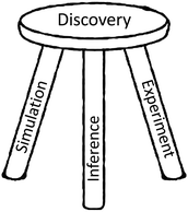
We coin the term science factory to denote a facility in which pervasive automation and parallelism allow for the integrated application of experiment, computational simulation, and AI inference to challenging discovery problems (see Fig. 1) without bottlenecks or human-induced delays. Such systems promise greatly accelerated progress in many domains of societal importance, from clean and plentiful energy to pandemic response and climate change.1,2Science factories require scale, generality, and programmability in order to support large scientific campaigns and achieve economies of scale for routine tasks. These are familiar concerns in conventional manufacturing, and also for HPC centers and commercial clouds,3 which may scale to millions of processing cores and support thousands of users. We seek to develop methods for the construction of science factories that are similarly scalable, general-purpose, and programmable.
Large systems of any type are typically constructed from modules, simpler subsystems that can be designed and constructed independently and then combined to provide desired functionality.4 A key concept in modular design is to hide implementation complexities behind simple interfaces.5
In the science factory context, modules can possess both physical and digital characteristics, and thus their interfaces need to encompass both form factor and programmatic elements.
Our investigations of these issues have led us to develop designs and prototype implementations for several elements of a modular science factory architecture. These include a six-function programmatic module interface; an associated (optional) physical form factor, the cart; methods for incorporating experimental apparatus into modules and for combining modules into workcells; methods for integrating with other elements of research infrastructure, such as data repositories, computers, and AI models; notations for specifying module and workcell configurations; methods for defining workflows and applications; and systems software for running applications on different workcells.
In the sections that follow, we describe these various elements of a science factory architecture and the results of experiments in which we employ a prototype implementation to run biology and materials science applications. We first provide some background in Section 2. Then, we introduce the concepts and mechanisms that we have developed to support modular architecture (Section 3); describe our experiences applying these methods in applications in biology and materials science (Section 4); discuss experiences and lessons learned (Section 5); and finally conclude and suggest future directions (Section 6). Additional details and pointers to code are provided in the ESI.†
Much of the work reported here has been conducted in Argonne's Rapid Prototyping Lab (RPL),7 a facility established to enable collaborative work on the design, development, and application of methods and systems for autonomous discovery.
2 Background
Automation has long been applied in science8,9 to increase throughput, enhance reliability, or reduce human effort. High-throughput experimentation systems are widely used to screen materials10,11 and potential drugs12–14 for desirable properties. Autonomous discovery systems, in which experiments are planned and executed by decision algorithms without human intervention,2,6,15–21 are potentially the next step in this trajectory. In principle, such systems can enable faster, more reliable, and less costly experimentation, and free human researchers for more creative pursuits. However, the adoption of autonomous platforms in science has thus far been limited, due in part at least to the diversity of tasks, and thus the wide variety of instruments, involved in exploratory research. Success going forward, we believe, requires substantial increases in scale and generality (for economies of scale), autonomy (for sustained hands-off operations), programmability (for flexibility), extensibility (to new instruments), and integration with computing and data resources, as well as resilience, safety, and security. These are all issues that we address in our work.As illustrated in Fig. 2, we can identify a continuum of flexibility in automation approaches. In integrated automation, a specialized device is manufactured to perform a specific task, such as for high-throughput characterization.22 Such devices are not intended to be repurposed to other tasks. In fixed automation, devices are connected in a fixed configuration; here, retooling for a new application may involve substantial design and engineering. In flexible automation,23–25 devices in fixed locations are connected by programmable manipulators that can move materials to any device within their reach; thus, retooling for a new application requires only substituting devices and reprogramming manipulators. In reconfigurable automation, reconfiguration is automated. (Reconfiguration, a feature of early computers,26 is also employed in microfluidics.27–30) In mobile automation, mobile robots are used to route materials to devices in arbitrary positions; thus, only programming is required to retool for a new application or environment.6 Finally, in the oxymoronic but sometimes useful human automation case, humans handle movement of materials between robotic stations, an approach used, for example, in Emerald Cloud Lab.31 In general, flexibility increases from left to right, and speed and reliability from right to left (Fig. 2). Such approaches can be combined, as in Amazon's automated warehouses, in which humans are engaged only when robots fail.
 | ||
| Fig. 2 Automation systems span a continuum of flexibility, speed, and reliability, from the integrated (e.g., as shown here, a microfluidic laboratory) to the fixed (e.g., Adam1), flexible (e.g., a bio workcell at Argonne), reconfigurable (e.g., a “cart” in Argonne's RPL), mobile (e.g., Liverpool's mobile robotic chemist6), and manual. | ||
Early autonomous discovery systems (e.g., the influential Adam1) were typically specialized for a single class of problems. Both economics and the inherent curiosity of scientists now demand multi-purpose systems that can easily be retargeted to different applications—and thus motivate solutions further to the right along the continuum of Fig. 2. Given a research goal, knowledge base, and set of appropriately configured devices, these systems may work iteratively to: (1) formulate hypotheses relevant to its goal; (2) design experiments to test these hypotheses, ideally based on existing protocols encoded in a reusable form;18,32–34 (3) manage the execution of experiments on available devices; and (4) integrate new data obtained from experiments into its knowledge base.
The third of these tasks involves automated execution of multi-step experimental protocols on multiple devices, with each step typically taking materials and/or data from previous steps as input. To avoid an explosion in the number of inter-device adapters, we want common physical and digital form factors for materials and data, respectively. Also important are uniform software interfaces, to simplify integration of new devices and reuse of code.
Conventional physical form factors are commonly used for handling samples (e.g., test tubes, multi-well plates, microcentrifuge tubes, Petri tubes, cuvettes) and for managing the experimental environment (e.g., microfluidics, Schlenk lines,35 glove boxes, fume hoods). Apparatus that are to interoperate in an SDL must either employ the same conventions or incorporate adapters, e.g., to move samples from one container to another or to move samples in and out of controlled environments.
Digitally, we need methods for specifying the actions to be performed (e.g., transfer sample, open door, turn on heater, take measurement) and for translating an action specification into commands to physical device(s). Various representations for actions have been proposed, with domain of applicability ranging from a single device36 to classes of experiment: e.g., the chemical description language XDL18 is an executable language for programming various experimental processes in chemistry, such as synthesis; ChemOS34,37 and the Robot Operating System (ROS)-based38 ARChemist39 have similar goals. (ROS is a potential common substrate for SDLs, but with limitations as we discuss in Section 5.) Aquarium40 defines Aquarium Workflow Language and Krill for sequencing steps and granular control of apparatus, respectively. BioStream32 and BioCoder33 support the representation of biology protocols. Li et al.41 describe a notation for materials synthesis.
The execution of a specification requires generating suitable commands for underlying devices: typically via digital communication, but in some cases, via robotic manipulation of physical controls,23 for example, XDL procedures, which express protocols in terms of reagents, reaction vessels, and steps to be performed (e.g., add, stir, heat), are compiled to instructions for a Chemputer architecture.18,35,42 Depending on the level of specification, general-purpose robotic methods (e.g., path planning) may be relevant at this stage.
An important concern in any robotic system, and certainly in automated laboratories, is monitoring to detect unexpected results: something that humans are often good at, but that can be hard to automate. Reported error rates in materials science experiments, of from 1 per 50 (ref. 43) to 1 per 500 (ref. 6) samples, show that automated detection and recovery are important. In other contexts, unexpected phenomena may be indicators of new science.
Autonomous discovery systems must also engage with computing and data resources. Vescovi et al.44 survey and describe methods for implementing computational flows that link scientific instruments with computing, data repositories, and other resources, leveraging Globus cloud-hosted services for reliable and secure execution. The materials acceleration operating system in cloud (MAOSIC) platform45 hosts analysis procedures in the cloud.
3 Towards a modular architecture
Our overarching goal is to create scalable, multi-purpose SDLs. To this end, we require methods that support: the integration of a variety of scientific instruments and other devices, and the reconfiguration of those devices to support different applications (to be multi-purpose); the incorporation of AI and related computational components (to be autonomous); and expansion of capacity and throughput by replicating components (to be scalable).Modularity of both hardware and software is vital to achieving these capabilities. A modular design defines a set of components, each of which hides complexities behind an abstraction and interface.4,5 In principle, modularity can facilitate the integration of new components (by implementing appropriate interfaces), rapid creation of new applications (by reusing existing components), system evolution (by improving components behind their interfaces), reasoning about system behavior (by focusing on abstractions rather than implementation details), and system scaling (by replicating components).
Realizing modularity in SDLs is challenging due to the wide variety of physical and logical resources (instruments, robots, computers, data stores, digital twins, AI agents, etc.) that scientists may wish to employ, and the many experimental protocols that they may want to implement on those resources—all limited only by budget and human, perhaps AI-assisted,46 ingenuity.
In this section, we describe our approach to building modular science factories. We first introduce key concepts and mechanisms and five applications that we use in this article to motivate and evaluate our work. Then, we describe in turn how we represent modules, workcells, workflows, and applications, after which we discuss experiments with a common hardware form factor; thoughts on workcell validation, assembly, and support; and preliminary work on digital twins and simulation.
3.1 Concepts
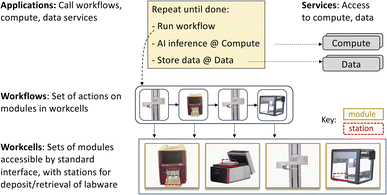
We introduce the central concepts that underpin our science factory architecture: see Fig. 3.| Operation | Description |
|---|---|
| about | Return description of module and its actions |
| action | Perform specified action |
| reset | Reset the module |
| resources | Return current resource levels, if applicable |
| state | Return state: “IDLE,” “BUSY,” or “ERROR’ |
| admin | Module-specific actions: e.g., home |
We list in Table 2 the modules employed in the work reported in this article. These modules encompass a considerable diversity of device types and interfaces; some diversity in sample exchange format, including 96-well plates47 and pipettes; and a variety of methods for transferring samples between modules.
| Class | Module | Description | Adapter |
|---|---|---|---|
| Synthesis | ot2 | Opentrons OT-2 liquid handling robot | ROS |
| solo | Hudson SOLO liquid handler | TCP | |
| chemspeed | ChemSpeed SWING liquid handling robot | TCP | |
| Plate prep | a4s_sealer | Azenta microplate sealer | REST |
| brooks_peeler | Azenta microplate seal remover | ROS | |
| Heat | biometra | Biometra TRobot II thermal cycler | ROS |
| liconic | LiCONiC StoreX STX88 | ROS | |
| Measure | camera | (e.g.) Logitech C930s | ROS |
| hidex | Hidex Sense microplate reader | TCP | |
| tecan | Tecan Infinite plate reader | TCP | |
| Manipulate | platecrane | Hudson PlateCrane EX microplate handler | ROS |
| pf400 | Precise Automation PreciseFlex 400 | ROS | |
| ur | UR5e robotic arm | ROS | |
| sciclops | Hudson SciClops microplate handler | ROS | |
| Mobility | mir | MiR AMR mobile robot base | REST |
We list in Table 3 the operations supported by the modules used in this work. The actions supported by a module can also be determined via the about operation.
| Class | Module | Actions |
|---|---|---|
| Synthesis | ot2 | run_protocol |
| solo | run_protocol | |
| chemspeed | open_lid, close_lid, run_program | |
| Plate prep | a4s_sealer | seal |
| brooks_peeler | peel | |
| Heat | biometra | open_lid, close_lid, run_program |
| liconic | get_current_temp, set_target_temp, get_current_humidity | |
| get_target_humidity, set_target_humidity, begin_shake, end_shake | ||
| load_plate, unload_plate | ||
| Measure | camera | grab_image |
| hidex | open_lid, close_lid | |
| tecan | measure_sample | |
| Manipulate | platecrane | transfer, remove_lid, replace_lid |
| pf400 | explore_workcell, transfer, remove_lid, replace_lid | |
| ur | transfer, run_urp_program | |
| sciclops | home, transfer, get_plate | |
| Mobility | mir | move, dock |
3.2 Motivating applications
We employ the five applications listed in Table 4 to motivate and evaluate the work presented in this article. These applications cover several modalities of scientific experimentation and collectively implement a variety of tasks that underpin many SDLs, including data handling and processing.| Name | Area | Description | Section |
|---|---|---|---|
| Color picker | Education | Mix liquid colors to match a target color | 4.1 |
| PCR | Biology | Polymerase chain reaction | 4.2 |
| Growth assay | Biology | Treatment effects on cellular growth | 4.3 |
| Electrochromic | Materials | Formulation, characterization of new polymer solutions | 4.4 |
| Pendant drop | Materials | Liquid sample acquisition from synchrotron beamline | 4.5 |
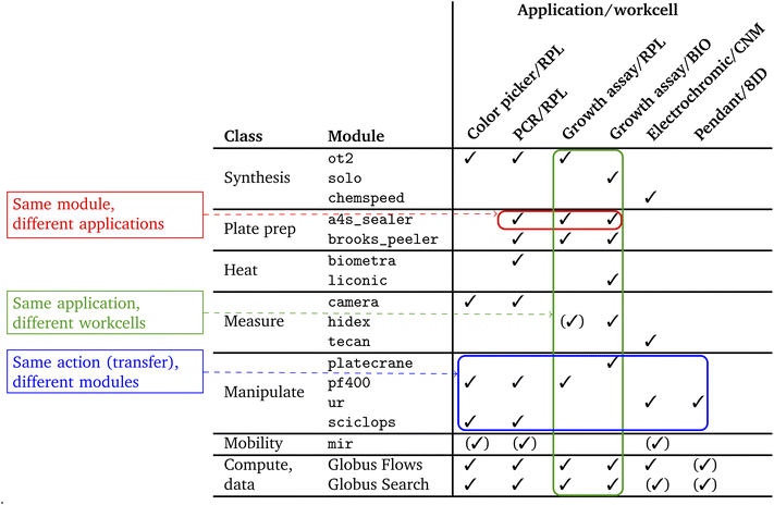
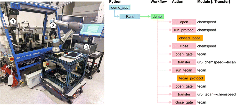
Color picker is a simple closed-loop application in which feedback from analysis of camera images is used to guide the mixing of colored liquids. PCR employs several biology instruments working in tandem to implement the polymerase chain reaction. Growth assay studies how treatments affect cell growth and can involve sample management over long periods without human intervention. Electrochromic, a material science application concerned with discovery of electrochromic polymers, employs chemspeed, tecan, and ur apparatus not used in the first three applications. Pendant drop similarly involves different patterns and different apparatus, including a synchrotron beamline, in this case for study of complex fluids.
We list in Table 5 the specifics of which application uses which module. The applications also make use of Globus services, as described in Section 3.6, to perform data analyses on remote computers during experiments and to publish both experimental results and provenance metadata describing how samples were created and processed. Table 3 shows the expanded list of actions implemented for each of the modules in Table 2.
3.3 Implementation of modules
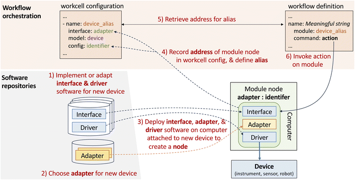
We now describe how we implement the various concepts introduced above, starting with the module. As noted, a module provides an implementation of the module interface of Table 1. Each module is represented by a node, a service to which applications can make requests that should cause the device to respond appropriately to Table 1 commands.Thus, integrating a new device, such as an a4s_sealer, involves the following steps (#1–3 in Fig. 4): (1) implement the logic required to process commands for the device; (2) implement the logic required to route messages; (3) deploy the software from #1 and #2 on a computer attached to the new device, start the node service, and record the address of the new node.
In order to simplify interactions with a variety of devices, which often come configured with specific software, we find it convenient to support a range of methods for handling requests and responses. For example, a4s_sealer has a REST API, so that to request a seal action we need to send it a REST message:
| POST/action params = {“action_handle”: seal, “action_vars”: {} } |
On the other hand, platecrane has a ROS interface; thus, to request that it fetch a plate from tower 1, we need to send, via a ROS service call to the platecrane ROS node's action service, the message:
| {“action_handle”: “get_plate”, “action_vars”: {“pos”: “tower1”} } |
Other devices support yet other communication protocols, such as custom TCP protocols or EPICS. To minimize the software changes required to integrate new devices, we allow the integrator to choose from among a number of adapters. In our work to date, we have found four classes of such adapters useful, as follows; others can easily be created:
• A REST adapter implements operations in terms of instrument-specific HTTP requests. Such adapters are written naturally in Python, using libraries that can handle required authentication and HTTP messaging with the specified REST endpoint.
• A TCP adapter maps operations into protobuf messages sent over a TCP socket to a server at a specified IP address and port.
• A ROS adapter translates operations into commands to a Robot Operating System (ROS) service38 associated with the component (for action, about, resources) or that extract information from a ROS topic associated with the component (for state).
• An EPICS adapter maps operations into channel access operations used by EPICS.48 It accesses a specified process variable and performs read and write operations as necessary to accomplish each operation and action.
• Interface: device-specific code that implements the module operations of Table 1 and that makes those operations available to remote clients via the module's chosen adapter.
• Adapter: adapter-specific code used to handle communications: currently, one of ROS, REST, TCP, or EPICS.
• Driver: device-specific code used to handle low-level interactions with the physical device, such as connection, raw command lists, error lists, and error handling.
• Description: device-specific CAD files, Universal Robot Definition File (URDF), and related configuration information, for use by simulations and for motion planning.
Given such software and a compatible physical device, a user can instantiate a module by installing the interface, adapter, and driver software on a computer that can interact with the device, and then starting the resulting node. The node is then accessible over the internet at an address specific to the new module.
3.4 Specifying workcells
We use a YAML-based notation to define workcells, as illustrated in Fig. 5b and in more detail in ESI A.1.† The YAML document lists a workcell's constituent modules and, for each, provides configuration information, including the location of modules and stations relative to the workcell origin.3.5 Specifying workflows
We use a similar YAML notation to specify workflows. As shown in Fig. 5c and ESI A.2 and A.3,† a workflow names a workcell, a list of modules within that workcell, and a sequence of actions to perform on those modules.3.6 Running applications
From Wei import experiment
| Experiment = experiment(wf_address, wf_port, experiment_name) experiment.run_job(workflow, payload=payload) |
To support such interactions, we leverage capabilities of the Globus platform, a set of cloud-hosted services that provide for the single sign-on and management of identities and credentials and delegation, and for managed execution of data transfers between storage systems, remote computations, data cataloging and retrieval operations, data analysis pipelines, and other activities.49 In each case, the Globus cloud service handles details such as monitoring of progress and retries on failure. These services have been used extensively, for example, to automate flows used to analyze data from, and provide on-line feedback to, X-ray source facilities.44 As an example of the use of Globus services, the color picker application of Section 4.1 (and ESI A.4†) employs Globus Compute50 to run a data analysis routine and Globus Search to publish experimental results to a cloud-hosted search index.
Other methods could also be used for access to computing and data services; we employ Globus because of its broad adoption, security, and reliability.
3.7 The cart as optional uniform hardware form factor
We have so far placed no constraints on how workcells are created, other than the practical need to have stations be accessible by manipulator(s). We can thus define highly compact assemblages of devices, such as the bio workcell depicted in Fig. 6.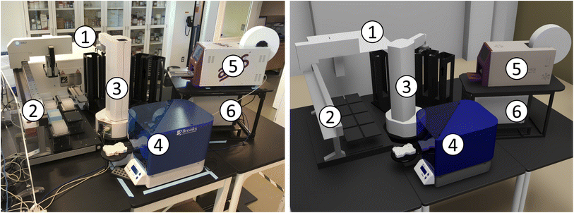 | ||
| Fig. 6 The bio workcell, shown in real (left) and virtual (right) representations, comprises (1) liconic, (2) solo, (3) platecrane, (4) brooks_peeler, (5) a4s_sealer, and (6) hidex modules. | ||
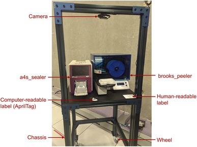
With the goal of simplifying workcell assembly and disassembly, we have experimented with the use of a common hardware form factor, the cart: see Fig. 7. A cart is built on a rigid chassis with horizontal dimensions 750 mm × 750 mm and height of 1020 mm, plus an additional frame for a camera, to which are attached devices to connect the cart securely to neighboring carts or other laboratory components; lockable wheels, so that the cart can be moved and then fixed in place; a built-in computer (e.g., Intel NUC or Raspberry Pi); a downward-looking camera on the top of the chassis; a power supply; identifying markers (currently, QR codes) that also serve as fiducials, i.e., as physical reference objects in known positions; and zero or more modules, such as the a4s_sealer and brooks_peeler seen in Fig. 7. Future designs might also include supplies, such as water and gas.
Given a set of carts and other equipment, we can construct a workcell by moving the carts into place and connecting them to each other. For example, we show in Fig. 8 the RPL workcell organization that combines eight carts with a Precise Automation PreciseFlex 400 (PF400) on a 2 m linear rail. Our current experiments in reconfiguration are carried out manually: we add each cart to the workcell by rolling it into place, engage registration pins to secure the cart in position, and connect its onboard power distribution strip to power on the laboratory floor. In future work, we intend to perform these assembly tasks automatically by using mobile tractor robots. This level of automation will require methods for providing power and material supplies to the carts without human intervention. Drive up docking for automatic charging of mobile units has been widely deployed for many applications including home vacuuming robots; batteries and wireless power delivery are two other possibilities. Available industrial solutions for utility coupling could be used for automated secure connection of power, liquids, and gases.
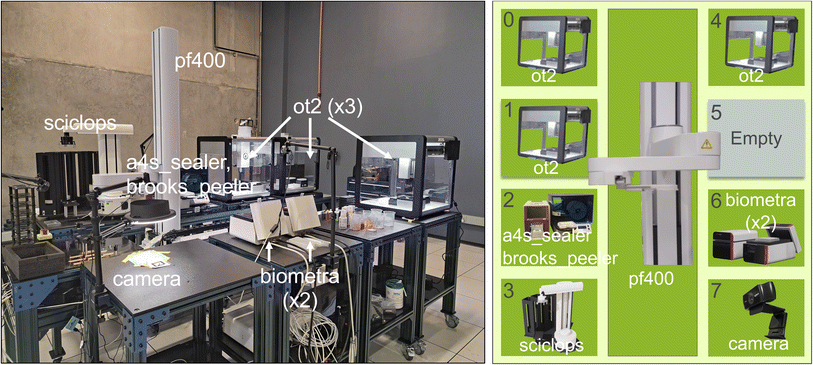 | ||
| Fig. 8 A photo (left) and schematic (right) of the RPL workcell, comprising eight carts, #0–#7, plus a central pf400 plate mover for transferring sample trays among carts. Modules are labeled with the nicknames in Table 2. Cart #5 is empty, and carts #2 and #6 each contain two modules. | ||
3.8 Workcell validation, assembly, and supply
Having described how we specify workcells and workflows, and run workflows on a workcell, we now discuss how other operations may be implemented.3.9 Digital twins and simulation
A digital twin of an SDL mimics the state and operations of the lab in a simulated environment. This simulated implementation can then be used for purposes such as workflow testing and debugging, scaling studies, algorithm development (e.g., via reinforcement learning), and training.Our workcell specification format includes model information for modules that can then be mapped to 3D models of the associated physical components: the description component noted in Section 3.3. Our specifications also include location information that can enable both placement of modules within a workcell and the placement of workcells in space. As discussed in Section 3.8, this location information can be obtained automatically when assembling workcells. Building on this information, we have employed NVIDIA's Omniverse platform to construct 3D models and visualizations of our workcells, as shown in Fig. 6 and 10. Using our workcell specification, such visualizations can be set up with ease, as many manufacturers will provide 3D models for their instruments and workcell location information can be used to automatically arrange instruments in the scene.
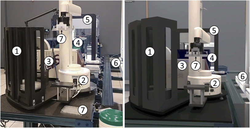 | ||
| Fig. 10 Other views of the RPL workcell of Fig. 8, shown in real (left) and virtual (right) representations. Modules, from front to back: (1) plate stack; (2) sciclops stacker; (3) a4s_sealer; (4) brooks_peeler; (5) ot2; and (6) pf400. Also visible are (7) 96-well plates: one held by the sciclops in each image, and a second on the table in the real case. | ||
We use NVIDIA's Isaac Sim54 application for simulation and digital twins, permitting exploration of both new equipment and workflows without requiring a physical deployment or the use of scarce resources. In Fig. 10 we show our simulation acting as a digital twin, mimicking the actions and physics of the real laboratory as the sciclops stacker lifts a 96-well plate. The digital twin is useful as a visualization and comparison tool to verify that the laboratory is operating as expected. In the future, we plan to use digital twins to predict the results of actions before they happen in the real laboratory and thus to identify unexpected situations such as robot collisions.
These simulation tools can also be used to train vision algorithms for flexible real-world error detection, a technique known as sim-to-real transfer.55 Many general-purpose sensors, such as cameras, cannot detect important situations out-of-the-box, and thus require training for specific situations that may arise in practice. Some such situations may be rare or difficult to replicate reliably, making the capture of real-world data impractical. Omniverse Replicator allows for the placement of (virtual) sensors in a digital twin, and thus the capture of data from a wide variety of custom-designed and randomized situations. State-of-the-art ray tracing and physics simulation packages built in to Omniverse ensure that these randomized situations look and act like real-world environments, so that training data are as realistic as possible.
4 Example applications
We provide implementation details, and in some cases also report results, for each of the five applications of Table 4.4.1 Color picker
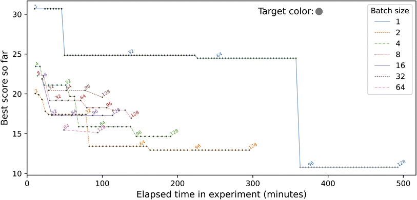
This simple demonstration application, inspired by Roch et al.34 and described in more detail by Baird and Sparks56,57 and Ginsburg et al.,58 seeks to find a mix of provided input colors that matches a specified target color. It proceeds by repeatedly creating a batch of B samples by combining different proportions of the input colors; taking a photo of the new samples; and comparing the photos with the target. The samples in the first batch are chosen at random, and then an optimization method is used to choose the samples in subsequent batches. In the study reported here, we fix the target color and the total number of samples (N = 128), while varying the batch size B from 1 to 128, by powers of two.Fig. 11 depicts an implementation of the application that targets four of the modules listed in Table 2: sciclops, ot2, pf400, and camera. We present a somewhat simplified version of this application in ESI A.4.† In brief, the Python program color_picker_app.py operates as follows.
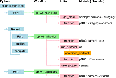 | ||
| Fig. 11 The color-picker application. The Python code, color_picker_app.py, implements logic that runs three distinct workflows, with the second (plus associated publish and compute steps) called repeatedly until termination criteria are satisfied. The orange box below the ot2 run_protocol action gives the name of the protocol file. Module names are as in Table 2. | ||
(1) It runs a first workflow, cp_wf_new_plate.yaml, which obtains a new plate from sciclops and places it at camera.
(2) It then repeatedly:
(a) Calls a second workflow, cp_wf_mixcolor.yaml (with specification presented in ESI A.3†) which transfers the plate from camera to ot2 and runs the ot2 protocol specified in the file combined_protocol.yaml to combine specified amounts of pigment from specified source wells to create B specified pigment mixtures; transfers the plate back to camera, and photographs the plate;
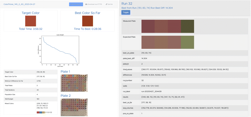
(b) Publishes the resulting data, by using Globus Search functions (see Fig. 12); and
(c) Invokes an analysis program, by using Globus Compute, to evaluate the latest data and (if the termination criteria are not satisfied) chooses the next set of colors to evaluate.
(3) Finally, it calls a third workflow, cp_wf_trashplate.yaml, to discard the plate.
We show in Fig. 13 results from running this application with different values for the batch size, B, using in each case a simple evolutionary solver. (The solver algorithm is interchangeable, allowing us to test the relative performance of different approaches; we are currently exploring the performance of alternatives.) To illustrate the use of data publication capabilities, we show in Fig. 12 two screenshots from the data portal hosted at the Argonne Community Data Coop (ACDC) repository.
This application can easily be adapted to target different apparatus (e.g., different color mixing equipment, or Baird and Sparks' closed-loop spectroscopy lab.57) It could also be modified to target multiple ot2s so as to speed up execution.
4.2 Polymerase chain reaction
Polymerase chain reaction (PCR),59 a technique used to amplify small segments of DNA, is important for many biological applications. Our PCR application uses six of the modules of Table 2: ot2, biometra, a4s_sealer, brooks_peeler, pf400, and sciclops. As shown in Fig. 14, it is implemented by a Python program that runs a workflow that retrieves a PCR plate from the sciclops plate stack; moves that plate to an ot2, where it runs a protocol that mixes the enzymes and DNA samples in the plate; moves the plate from ot2 to a4s_sealer, where it seals the plate; moves the sealed plate to biometra, where it runs a program that heats and cools the reagents in sequence to facilitate the PCR reactions; moves the plate from biometra to brooks_peeler, where it peels the plate; moves the plate to camera, where it takes a picture; and finally transfers the plate to an exchange location where it can be used in further workflows or, after re-sealing, transported to cold storage for later use. We present this workflow's specification in ESI A.2.†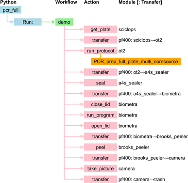 | ||
| Fig. 14 PCR application. Module names are as in Table 2. | ||
4.3 Growth assays for bacterial treatments
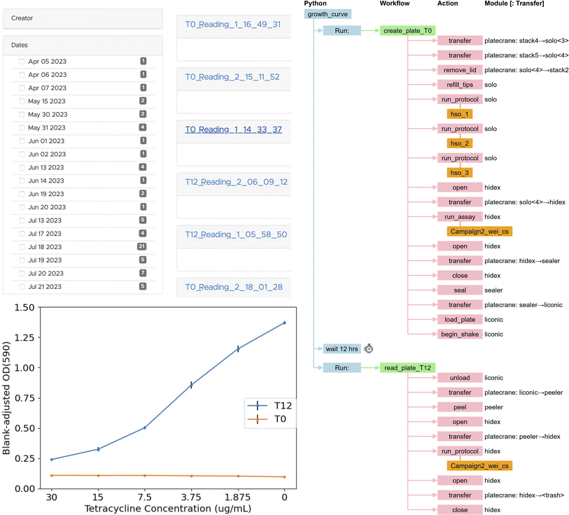
This application performs automated experiments to generate dose–response curves. These dose–response curves are useful for many microbiology research objectives, including cancer therapeutic development and antibiotic discovery. Our work in predicting antimicrobial response60,61 and tumor response to small molecules,62 coupled with laboratory screening, provides an ideal use case for automation that moves towards fully autonomous discovery.Our growth assay application employs six modules of Table 2: solo, platecrane, a4s_sealer, brooks_peeler, liconic, and hidex. As shown in Fig. 15, it is implemented by a Python program that runs two workflows per assay plate created. The first workflow contains all steps required to create the assay plate, including liquid handling actions as well as steps to take the initial absorbance readings on the assay plate, while the second runs after a timed wait for incubation and contains all steps required to take the final absorbance readings of the assay plate.
4.4 Autonomous synthesis of electrochromic polymers
Jie Xu and her team have developed an SDL63 for the autonomous synthesis of electrochromic polymers (ECPs), a type of polymer material employed in applications such as smart windows, displays, and energy-efficient devices.64 The use of polymer materials for such applications can offer diversity and ease at synthesizability following simple synthetic steps. However, the interplay between multiple parameters, including the physicochemical properties of the monomers and their formulations, make it difficult to predict intuitively the performance of these systems. Thus, researchers must develop and characterize a wide range of formulation candidates through time-consuming experimentation. To overcome these limitations, they built a self-driving laboratory to synthesize ECPs by combining different monomers in certain ratios and lengths so as to modulate the color.This SDL employs chemspeed, ur, and tecan modules. The polymer synthesis process is coordinated by a Python application that executes a single workflow: see Fig. 16. The workflow first retrieves the plate with the synthesized polymers from chemspeed. It then transfers the plate to tecan, which implements a protocol to measure the absorption spectra with a UV-vis measurement device. After the completion of measurements, the plate is transferred from tecan back to chemspeed. The collected data from tecan are analyzed to determine the color coordinates of the samples. This information is provided to a neural network to obtain recommendations for the next batch of materials.
4.5 Pendant drop for study of complex fluids
Robotic pendant drop provides an end-to-end automated, μs-resolved XPCS workflow for studying the dynamics and structures of complex fluids. Ozgulbas et al.65 recently demonstrated that Brownian dynamics of nanoparticle colloid in a pendant drop is consistent with the reference setup such as thin-walled quartz capillaries. Furthermore, the pendant drop setup can be integrated with a robotic arm (UR3e) to fully automate sample preparation, characterization, and disposal. This approach addresses limitations associated with manual sample changes at the 4th-generation coherent synchrotron X-ray sources that are being constructed and commissioned around the world.In a robotic pendant drop setup, the use of an electronic pipette enables the dispense and withdrawal of the pendant drop into a pipette tip. The electronic pipette is mounted on a robotic arm that can readily access vials of the stock liquid samples and a 96-well PCR plate for precise and repeatable generation of complex fluid samples with tailored composition profiles. The end-to-end automation of the complex fluid X-ray scattering workflow also enables nescience that requires sample handling at non-ambient environments (e.g., high/low temperature, anoxic). Finally, the robotic pendant drop is programmed with workflows, which provides a modular approach that not only improves the reusability of the robotic code but also facilitates AI-driven, physics-aware self-programming robots at the Advanced Photon Source of Argonne National Laboratory in the near future.
The experiments just described used the physical apparatus and application depicted in Fig. 17. The application uses a single module, an UR3e arm, to perform the following steps. The arm, initially positioned at the home base, picks up the pipette from the docking location by activating the locking mechanism of the tool changer, and attaches a tip to the pipette from the tip bin. Then, it prepares the sample on the 96-well plate by driving the pipette. Next, to obtain the measurements with the prepared sample, the pipette is placed on the docking location and a droplet is formed by dispensing the sample; with an optical microscope used to monitor the optical appearance of the drop during alignment and the SA-XPCS measurement. Lastly, the pipette is picked up from the docking location, the tip is ejected to the trash bin, and the pipette is placed back at the docking location.
The robotic pendant drop provides an end-to-end automated solution for studies of dynamics and structures of complex fluid using light-scattering techniques such as dynamic light scattering, X-ray/neutron scattering, and XPCS. This automated experimental protocol can be combined with the data managing workflow,66 high-throughput analysis,67 open-source graphical user interface (GUI)68 and AI-assisted data interpretation69 to provide a self-driving experimental station at future user facilities, paving the way to autonomous material discovery driven by domain-science-specific questions from facility users.
5 Discussion
5.1 Ability to integrate different instruments
As noted in Section 3.3, the integration of a new device into our architecture requires implementations of four software components to implement the operations on Table 1. To date, we have performed this integration for 15 instruments of quite different types. We found that the ease or difficulty of this integration varies a great deal across device. The easiest are those, like ot2, that provide Python libraries for interacting directly with the device. Somewhat more difficult are those, like sciclops, that expose a serial port and document a pre-defined list of commands that we can send with Python serial libraries. The most difficult are those that use custom communication protocols. For example, hidex uses a custom. NET-specific connection that we can access only through C#-based connection objects from a specific. NET version. In future work, we are also interested in automating the process by which instruments are integrated into the system. This problem is arguably akin to automated interface discovery, for which fuzzing70 could be employed. Large language models may also have promise.46,715.2 Suitability of ROS
We initially planned to use ROS to control and monitor all experimental apparatus. However, we found that while ROS was useful in some contexts (e.g., for controlling mobile robots like mir, for which ROS path planing libraries were helpful), it introduced unhelpful complexity in others, such as for instruments that run Windows or that produce large quantities of data. Furthermore, the generality of ROS is not needed in most cases: many of our instruments are not general-purpose robots but rather devices that each perform just a few relatively simple operations. Thus, we arrived at our architecture based on the interface of Table 1.5.3 Ability to retarget applications
An important goal of our work is to enable porting of applications between workcells with different configurations, with few or no changes to application logic. As an example of successful transfer, the growth assay application was initially developed, as described in Section 4.3, on the RPL workcell of Fig. 10. Once working there, we transferred it to the bio workcell of Fig. 6 in another lab at Argonne, with different equipment (platecrane rather than pf400 for transfer actions, solo rather than ot2 for liquid handling). Only the module names in the workflow needed to be changed to retarget the workflow to different hardware in a different configuration.5.4 Ability to reuse workflows
Another important goal is to enable reuse of workflows across applications. As an example of reuse, the workflow used in the growth assay application shares many steps with the workflow used in the PCR application.5.5 Notation
We have chosen in this work to represent workcells and workflows as YAML documents and applications as Python programs, with the goal of simplifying the configuration (and analysis: see Section 3.8) of the first two entity types without sacrificing the generality offered by a programming language. We have found this approach to work well for our target applications, but other approaches (e.g., a programming language for workflows, or static configurations for complete applications) may prove advantageous in other contexts.5.6 Education and training
Hands-on laboratory work has long been an important element of experimental science education. Yet the role of researchers working with SDLs is not to perform experiments themselves, but to plan, monitor, and guide SDL activities—tasks that require new skills, and thus new approaches to education and training.72 We may also wonder whether hands-on experimental skills become less important—and, if not, how those skills are to be taught if science factories or other remote SDLs reduce opportunities for hands-on access.5.7 Concurrency
Our current infrastructure does not support concurrent execution of workflow steps, as would be required, for example, to drive multiple OT2s in the color-picker experiment. Providing such support will not be difficult. One approach would be to allow users to launch multiple workflows at once, and then schedule execution of individual steps within each workflow subject to appropriate constraints. For example, we might want to ensure that (a) each workflow step is scheduled only after the preceding step in the workflow has completed, and (b) a transfer step that is to retrieve a sample holder from station a and deposit it at station b is scheduled only when a is occupied and b is empty.5.8 Failures
The abilities first to detect errors and then to respond to them without human intervention are crucial requirements for any autonomous discovery system. We find it useful to distinguish among three types of error based on how the error evidences itself during an experiment: (1) a software error is detected and reported by an instrument or its control software in a way that allows high-level software to respond programmatically. For example, a response to an action command indicating that an instrument is offline can allow the workflow executor to reset the instrument or request human assistance to restart it. (2) An operational error is one that prevents a workflow from proceeding but that is not detected and reported as a software error. For example, a misaligned manipulator might drop rather than deposit a sample during a transfer command, but report correct completion. One approach to detecting such errors is monitoring, out of band from the instrument, with cameras or other sensors. Monitoring results can then be used to diagnose errors and perhaps even to drive remedial actions. (3) An experiment error occurs when a workflow performs its actions completely and correctly, but produces an unexpected result: e.g., cells do not grow or PCR does not take place. Such occurrences may require changes to the experimental workflow or may represent new knowledge.Ideally, all erroneous conditions would be detected and reported as software errors or operational errors, so that only true experiment errors are reported as such. To this end, we continue to review operational errors and, wherever possible either eliminate them (e.g., by fixing race conditions in device interfaces) or transform them into software errors (e.g., by adding checks for exhausted reagents).
5.9 Continuous operation
Large-scale, long-term SDL operation requires the automation of support functions (e.g., replenishing consumables, disposing of waste, correcting operational errors) that in simpler settings might be handled by humans. We propose time-without-human-intervention as a useful metric for quantifying the level of automation achieved for both individual applications and a complete science factory running a mixed workload.6 Summary and conclusions
We have reported on concepts and mechanisms for the construction and operation of science factories: large-scale, general-purpose, simulation- and AI-enabled self-driving laboratories. We presented methods for defining individual modules, grouping modules to form workcells, and running applications on workcells. We described how a variety of instruments and other devices can work with these methods, and how modules can be linked with AI models, data repositories, and other computational capabilities. We also demonstrated the ability to reuse modules and workcells for different applications, to migrate applications between workcells, and to reuse workflows within applications for different purposes.We are working to expand the range of devices, workflows, environments, and applications supported by our science factory architecture; link multiple workcells with mobile robots; incorporate support functions such as supply and waste disposal; run increasingly ambitious science studies; and evaluate performance and resilience. We are also working to expand our simulation capabilities to enable investigation of scaling issues and ultimately the design and validation of science factories in which hundreds or thousands of workcells support many concurrent experiments.
The science factory architecture that we present here is a work in progress. Its modularity makes it easy to extend with new instruments, AI and other computational methods, and new workflows and applications, and its simplicity enables rapid deployment in new settings. We welcome collaboration on any aspect of its implementation and application.
Data availability
Data and code associated with this article are at https://ad-sdl.github.io/wei2023, as described in the ESI.†Author contributions
IF, RV, BB, TB, MH, AR, and RS contributed to the conception of the modular autonomous discovery architecture. RV, CS, TG, KH, DO, AS, RB, BB, TB, KC, MH, AR, and IF contributed to the design of the system described. RV, MH, IF, and DO designed the modular carts and table. RV, IF, DO, KH, CS, TB, and AS selected and designed the exemplar workflows. DO and QZ led the development and data collection for the pendant drop application. DO and RB designed and produced the pendant drop simulation and video. DO, AV, and JX led the development and data collection for the autonomous synthesis of electrochromic polymers application. RV and TG developed the data portals associated with the experiments. RV and CS managed the design and development team. The developers of each software module, maintained in GitHub, are: RV, TG, KH for the main module; RV, DO, and TG (camera); DO and RV (pf400, a4s_sealer, brooks_peeler, ur); DO, AS, and RV (platecrane, sciclops); KH, AS, and DO, RV (ot2); AS and DO (biometra); DO and AV (chemspeed, tecan); RB (rpl_omniverse, the virtual reality simulation of the modular workcell). DO designed and implemented the ROS RViz real time visualization. IF led the writing effort with RV, TG, KH, DO, CS, AS, RB, BB, TB, KC, MH, AR, and AV contributing to the writing, editing, and reviewing.Conflicts of interest
There are no conflicts of interest to declare.Acknowledgements
We are grateful to Argonne colleagues with whom we have worked on SDLs, including Gyorgy Babnigg, Pete Beckman, Max Delferro, Magali Ferrandon, Millie Firestone, Kawtar Hafidi, David Kaphan, Suresh Narayanan, Mike Papka, Young Soo Park, Rick Stevens, and Logan Ward. We thank also Eric Codrea, Yuanjian Liu, Priyanka Setty, and other students for their contributions, and Ryan Chard, Nickolaus Saint, and others in the Globus team for their ongoing support. We have benefited from conversations with many working in this area, including Sterling Baird, Andy Cooper, Lee Cronin, Jason Hattrick-Simpers, Ross King, Phil Maffettone, and Joshua Schrier. This work would not have been possible without much appreciated support from the leadership and staff of Argonne's Leadership Computing Facility and Advanced Photon Source. This work was supported in part by Laboratory Directed Research and Development funds at Argonne National Laboratory from the U.S. Department of Energy under Contract DE-AC02-06CH11357.Notes and references
- R. D. King, J. Rowland, S. G. Oliver, M. Young, W. Aubrey and E. Byrne, et al., The automation of science, Science, 2009, 324(5923), 85–89 CrossRef CAS PubMed.
- A. Aspuru-Guzik and K. Persson, Materials Acceleration Platform: Accelerating Advanced Energy Materials Discovery by Integrating High-Throughput Methods and Artificial Intelligence, Mission Innovation, 2018, https://nrs.harvard.edu/urn-3:HUL.InstRepos:35164974 Search PubMed.
- L. A. Barroso, U. Hölzle and P. Ranganathan, The Datacenter as a Computer: An Introduction to the Design of Warehouse-Scale Machines, Springer Nature, 2019 Search PubMed.
- C. Y. Baldwin and K. B. Clark, Chapter 3: What is modularity, in Design Rules: The Power of Modularity, MIT Press, 2000 Search PubMed.
- D. L. Parnas, On the Criteria To Be Used in Decomposing Systems into Modules, Commun. ACM, 1972, 15, 1053–1058 CrossRef.
- B. Burger, P. M. Maffettone, V. V. Gusev, C. M. Aitchison, Y. Bai and X. Wang, et al., A mobile robotic chemist, Nature, 2020, 583(7815), 237–241 CrossRef CAS PubMed.
- Argonne National Laboratory's Rapid Prototyping Lab, https://rpl.cels.anl.gov, accessed December 2022.
- K. Olsen, The first 110 years of laboratory automation: technologies, applications, and the creative scientist, J. Lab. Autom., 2012, 17(6), 469–480 CrossRef PubMed.
- J. S. Lindsey, A retrospective on the automation of laboratory synthetic chemistry, Chemom. Intell. Lab. Syst., 1992, 17(1), 15–45 CrossRef CAS.
- M. L. Green, I. Takeuchi and J. R. Hattrick-Simpers, Applications of high throughput (combinatorial) methodologies to electronic, magnetic, optical, and energy-related materials, J. Appl. Phys., 2013, 113(23), 231101 CrossRef.
- L. Cheng, R. S. Assary, X. Qu, A. Jain, S. P. Ong and N. N. Rajput, et al., Accelerating electrolyte discovery for energy storage with high-throughput screening, J. Phys. Chem. Lett., 2015, 6(2), 283–291 CrossRef CAS PubMed.
- M. J. Wildey, A. Haunso, M. Tudor, M. Webb and J. H. Connick, High-throughput screening, Annu. Rep. Med. Chem., 2017, 50, 149–195 CAS.
- G. Schneider, Automating drug discovery, Nat. Rev. Drug Discovery, 2018, 17(2), 97–113 CrossRef CAS PubMed.
- W. Zeng, L. Guo, S. Xu, J. Chen and J. Zhou, High-throughput screening technology in industrial biotechnology, Trends Biotechnol., 2020, 38(8), 888–906 CrossRef CAS PubMed.
- P. Nikolaev, D. Hooper, F. Webber, R. Rao, K. Decker and M. Krein, et al., Autonomy in materials research: A case study in carbon nanotube growth, npj Comput. Mater., 2016, 2(1), 1–6 CrossRef.
- A. Sparkes, W. Aubrey, E. Byrne, A. Clare, M. Khan and M. Liakata, et al., Towards Robot Scientists for autonomous scientific discovery, Autom. Exp., 2010, 2(1), 1–11 CrossRef PubMed.
- E. Stach, B. DeCost, A. G. Kusne, J. Hattrick-Simpers, K. A. Brown and K. G. Reyes, et al., Autonomous experimentation systems for materials development: A community perspective, Matter, 2021, 4(9), 2702–2726 CrossRef.
- S. Steiner, J. Wolf, S. Glatzel, A. Andreou, J. Granda and G. Keenan, et al., Organic synthesis in a modular robotic system driven by a chemical programming language, Science, 2019, 363(6423), eaav2211 CrossRef CAS PubMed.
- M. Abolhasani and E. Kumacheva, The rise of self-driving labs in chemical and materials sciences, Nature Synthesis, 2023, 1–10 Search PubMed.
- H. G. Martin, T. Radivojevic, J. Zucker, K. Bouchard, J. Sustarich and S. Peisert, et al., Perspectives for self-driving labs in synthetic biology, Curr. Opin. Biotechnol., 2023, 79, 102881 CrossRef CAS PubMed.
- P. M. Maffettone, P. Friederich, S. G. Baird, B. Blaiszik, K. A. Brown and S. I. Campbell, et al., What is missing in autonomous discovery: Open challenges for the community, Digital Discovery, 2023 Search PubMed.
- D. W. McClymont and P. S. Freemont, With all due respect to Maholo, lab automation isn't anthropomorphic, Nat. Biotechnol., 2017, 35(4), 312–314 CrossRef CAS PubMed.
- N. Yachie and T. Natsume, Robotic crowd biology with Maholo LabDroids, Nat. Biotechnol., 2017, 35(4), 310–312 CrossRef CAS PubMed.
- P. Shiri, V. Lai, T. Zepel, D. Griffin, J. Reifman and S. Clark, et al., Automated solubility screening platform using computer vision, Iscience, 2021, 24(3), 102176 CrossRef CAS PubMed.
- B. P. MacLeod, F. G. Parlane, A. K. Brown, J. E. Hein and C. P. Berlinguette, Flexible automation accelerates materials discovery, Nat. Mater., 2022, 21(7), 722–726 CrossRef CAS PubMed.
- J. W. Mauchly, The ENIAC, in A History of Computing in the Twentieth Century, Elsevier, 1980, pp. 541–550 Search PubMed.
- F. Paratore, V. Bacheva, M. Bercovici and G. V. Kaigala, Reconfigurable microfluidics, Nat. Rev. Chem, 2022, 6(1), 70–80, DOI:10.1038/s41570-021-00343-9.
- E. A. Galan, H. Zhao, X. Wang, Q. Dai, W. T. Huck and S. Ma, Intelligent microfluidics: The convergence of machine learning and microfluidics in materials science and biomedicine, Matter, 2020, 3(6), 1893–1922 CrossRef.
- V. B. Kothamachu, S. Zaini and F. Muffatto, Role of digital microfluidics in enabling access to laboratory automation and making biology programmable, SLAS Technol., 2020, 25(5), 411–426 CrossRef CAS PubMed.
- A. A. Volk, R. W. Epps, D. T. Yonemoto, B. S. Masters, F. N. Castellano and K. G. Reyes, et al., AlphaFlow: Autonomous discovery and optimization of multi-step chemistry using a self-driven fluidic lab guided by reinforcement learning, Nat. Commun., 2023, 14(1), 1403 CrossRef CAS PubMed.
- M. Segal, An operating system for the biology lab, Nature, 2019, 573(7775), S112–S113 CrossRef CAS PubMed.
- W. Thies, J. P. Urbanski, T. Thorsen and S. Amarasinghe, Abstraction layers for scalable microfluidic biocomputing, Nat. Comput., 2008, 7, 255–275 CrossRef.
- V. Ananthanarayanan and W. Thies, BioCoder: A programming language for standardizing and automating biology protocols, J. Biol. Eng., 2010, 4(1), 1–13 CrossRef PubMed.
- L. M. Roch, F. Häse, C. Kreisbeck, T. Tamayo-Mendoza, L. P. Yunker and J. E. Hein, et al., ChemOS: An orchestration software to democratize autonomous discovery, PLoS One, 2020, 15(4), e0229862 CrossRef CAS PubMed.
- L. Cronin, N. Bell, F. Boser, A. Bubliauskas, D. Willcox and V. Luna, Autonomous Execution of Highly Reactive Chemical Transformations in the Schlenkputer, ChemRxiv, 2023, preprint, DOI:10.26434/chemrxiv-2023-g3pkc.
- E. J. Chory, D. W. Gretton, E. A. DeBenedictis and K. M. Esvelt, Enabling high-throughput biology with flexible open-source automation, Mol. Syst. Biol., 2021, 17(3), e9942 CrossRef PubMed.
- M. Sim, M. G. Vakili, F. Strieth-Kalthoff, H. Hao, R. Hickman and S. Miret, et al., ChemOS 2.0: An orchestration architecture for chemical self-driving laboratories, ChemRxiv, 2023, preprint, DOI:10.26434/chemrxiv-2023-v2khf.
- M. Quigley, K. Conley, B. Gerkey, J. Faust, T. Foote and J. Leibs, et al., ROS: An open-source Robot Operating System, in ICRA Workshop on Open Source Software, Kobe, Japan, 2009, vol. 3.2, p. 5 Search PubMed.
- H. Fakhruldeen, G. Pizzuto, J. Glowacki and A. I. Cooper, ARChemist: Autonomous robotic chemistry system architecture, in International Conference on Robotics and Automation, IEEE, 2022, pp. 6013–6019 Search PubMed.
- J. Vrana, O. de Lange, Y. Yang, G. Newman, A. Saleem and A. Miller, et al., Aquarium: Open-source laboratory software for design, execution and data management, Synth. Biol., 2021, 6(1), ysab006 CrossRef CAS PubMed.
- J. Li, Y. Tu, R. Liu, Y. Lu and X. Zhu, Toward “on-demand” materials synthesis and scientific discovery through intelligent robots, Advanced Science, 2020, 7(7), 1901957 CrossRef CAS PubMed.
- D. Angelone, A. Hammer, S. Rohrbach, S. Krambeck, J. Granda and J. Wolf, et al., Convergence of multiple synthetic paradigms in a universally programmable chemical synthesis machine, Nat. Chem., 2021, 13(1), 63–69 CrossRef CAS PubMed.
- B. P. MacLeod, F. G. Parlane, T. D. Morrissey, F. Häse, L. M. Roch and K. E. Dettelbach, et al., Self-driving laboratory for accelerated discovery of thin-film materials, Sci. Adv., 2020, 6(20), eaaz8867 CrossRef CAS PubMed.
- R. Vescovi, R. Chard, N. D. Saint, B. Blaiszik, J. Pruyne and T. Bicer, et al., Linking scientific instruments and computation: Patterns, technologies, and experiences, Patterns, 2022, 3(10), 100606 CrossRef PubMed.
- J. Li, J. Li, R. Liu, Y. Tu, Y. Li and J. Cheng, et al., Autonomous discovery of optically active chiral inorganic perovskite nanocrystals through an intelligent cloud lab, Nat. Commun., 2020, 11(1), 2046 CrossRef CAS PubMed.
- F. Stella, C. Della Santina and J. Hughes, How can LLMs transform the robotic design process?, Nat. Mach. Intell., 2023, 1–4 Search PubMed.
- ANSI/SLAS 4-2004 (R2012): Microplates – Well Positions, Society for Laboratory Automation and Screening, 2011, https://www.slas.org/SLAS/assets/File/public/standards/ANSI_SLAS_4-2004_WellPositions.pdf Search PubMed.
- Experimental Physics and Industrial Control System (EPICS), https://epics.anl.gov, accessed August 2022 Search PubMed.
- R. Chard, J. Pruyne, K. McKee, J. Bryan, B. Raumann and R. Ananthakrishnan, et al., Globus automation services: Research process automation across the space-time continuum, Future Generat. Comput. Syst., 2023, 142, 393–409 CrossRef.
- R. Chard, Y. Babuji, Z. Li, T. Skluzacek, A. Woodard, B. Blaiszik and et al., FuncX: A Federated Function Serving Fabric for Science, in 29th International Symposium on High-Performance Parallel and Distributed Computing. HPDC '20, Association for Computing Machinery, New York, NY, USA, 2020, pp. 65–76, DOI:10.1145/3369583.3392683.
- J. Kreps, N. Narkhede and J. Rao, Kafka: A distributed messaging system for log processing, in Proceedings of the NetDB, Athens, Greece, 2011, vol. 11, pp. 1–7 Search PubMed.
- Á. Wolf, D. Wolton, J. Trapl, J. Janda, S. Romeder-Finger and T. Gatternig, et al., Towards robotic laboratory automation Plug & Play: The “LAPP” framework, SLAS Technol., 2022, 27(1), 18–25 CrossRef PubMed.
- Á. Wolf, S. Romeder-Finger, K. Széll and P. Galambos, Towards robotic laboratory automation Plug & Play: Survey and concept proposal on teaching-free robot integration with the LAPP digital twin, SLAS Technol., 2023, 28(2), 82–88 CrossRef PubMed.
- NVIDIA Isaac Sim, https://developer.nvidia.com/isaac-sim, accessed July 2023.
- W. Zhao, J. P. Queralta and T. Westerlund, Sim-to-real transfer in deep reinforcement learning for robotics: A survey, in IEEE Symposium Series on Computational Intelligence, IEEE, 2020, pp. 737–744 Search PubMed.
- S. G. Baird and T. D. Sparks, What is a minimal working example for a self-driving laboratory?, Matter, 2022, 5(12), 4170–4178 CrossRef.
- S. G. Baird and T. D. Sparks, Building a “Hello World” for self-driving labs: The Closed-loop Spectroscopy Lab Light-mixing demo, STAR Protoc., 2023, 4(2), 102329 CrossRef CAS PubMed.
- T. Ginsburg, K. Hippe, R. Lewis, D. Ozgulbas, A. Cleary and R. Butler, et al., Exploring Benchmarks for Self-Driving Labs using Color Matching, arXiv, 2023, preprint, arXiv:2310.00510, https://arxiv.org/abs/2310.00510 Search PubMed.
- J. Bartlett and D. Stirling, A short history of the polymerase chain reaction, in PCR Protocols, Humana Press, 2003, pp. 3–6 Search PubMed.
- P. F. McDermott and J. J. Davis, Predicting antimicrobial susceptibility from the bacterial genome: A new paradigm for one health resistance monitoring, J. Vet. Pharmacol. Ther., 2021, 44(2), 223–237 CrossRef PubMed.
- M. Nguyen, R. Olson, M. Shukla, M. VanOeffelen and J. J. Davis, Predicting antimicrobial resistance using conserved genes, PLoS Comput. Biol., 2020, 16(10), e1008319 CrossRef CAS PubMed.
- F. Xia, M. Shukla, T. Brettin, C. Garcia-Cardona, J. Cohn and J. E. Allen, et al., Predicting tumor cell line response to drug pairs with deep learning, BMC Bioinf., 2018, 19, 71–79 CrossRef PubMed.
- A. Vriza, H. Chan and J. Xu, Self-driving laboratory for polymer electronics, Chem. Mater., 2023, 35(8), 3046–3056 CrossRef CAS.
- T. Abidin, Q. Zhang, K. L. Wang and D. J. Liaw, Recent advances in electrochromic polymers, Polymer, 2014, 55(21), 5293–5304 CrossRef CAS.
- D. Y. Ozgulbas, D. Jensen Jr, R. Butler, R. Vescovi, I. T. Foster and M. Irvin, et al., Robotic pendant drop: containerless liquid for μs-resolved, AI-executable XPCS, Light: Sci. Appl., 2023, 12(1), 196 CrossRef CAS PubMed.
- Q. Zhang, E. M. Dufresne, Y. Nakaye, P. R. Jemian, T. Sakumura and Y. Sakuma, et al., 20 μs-resolved high-throughput X-ray photon correlation spectroscopy on a 500k pixel detector enabled by data-management workflow, J. Synchrotron Radiat., 2021, 28(Pt 1), 259–265 CrossRef PubMed.
- F. Khan, S. Narayanan, R. Sersted, N. Schwarz and A. Sandy, Distributed X-ray photon correlation spectroscopy data reduction using Hadoop MapReduce, J. Synchrotron Radiat., 2018, 25(Pt 4), 1135–1143 CrossRef PubMed.
- M. Chu, J. Li, Q. Zhang, Z. Jiang, E. M. Dufresne and A. Sandy, et al., pyXPCSviewer: an open-source interactive tool for X-ray photon correlation spectroscopy visualization and analysis, J. Synchrotron Radiat., 2022, 29(Pt 4), 1122–1129 CrossRef CAS PubMed.
- J. P. Horwath, X. M. Lin, H. He, Q. Zhang, E. M. Dufresne and M. Chu, et al., Elucidation of Relaxation Dynamics Beyond Equilibrium Through AI-informed X-ray Photon Correlation Spectroscopy, arxiv, 2022, preprint, arXiv:2212.03984, DOI:10.48550/arXiv.2212.03984.
- J. Corina, A. Machiry, C. Salls, Y. Shoshitaishvili, S. Hao and C. Kruegel, et al., DIFUZE: Interface aware fuzzing for kernel drivers, in ACM SIGSAC Conference on Computer and Communications Security, 2017, pp. 2123–2138 Search PubMed.
- M. Skreta, N. Yoshikawa, S. Arellano-Rubach, Z. Ji, L. B. Kristensen and K. Darvish, et al., Errors are Useful Prompts: Instruction Guided Task Programming with Verifier-Assisted Iterative Prompting, arXiv, 2023, preprint, arXiv:230314100, DOI:10.48550/arXiv.2303.14100.
- K. L. Snapp and K. A. Brown, Driving School for Self-Driving Labs, Digital Discovery, 2023, 2, 1620–1629 RSC.
Footnote |
| † Electronic supplementary information (ESI) available. See DOI: https://doi.org/10.1039/d3dd00142c |
| This journal is © The Royal Society of Chemistry 2023 |

