 Open Access Article
Best practice for sampling in automated parallel synthesizers†
Michael
Ringleb
ab,
Timo
Schuett
ab,
Stefan
Zechel
ab and
Ulrich S.
Schubert
 *ab
*ab
aLaboratory of Organic and Macromolecular Chemistry (IOMC), Friedrich Schiller University Jena, 07743 Jena, Germany. E-mail: ulrich.schubert@uni-jena.de
bJena Center for Soft Matter (JCSM), Friedrich Schiller University Jena, 07743 Jena, Germany
First published on 17th October 2023
Abstract
The ongoing digitalization leads to a higher degree of automation in chemical and material research. Particularly important is the sampling of reactions in order to monitor reaction kinetics and to enable online- and offline characterization. The sampling process must be well designed to take full advantage of the automated method without compromising analytical results compared to manual sampling. We present a new method for taking samples in an automated fashion for the application in synthesis robots and liquid handling robots obtained by simple additive manufacturing of a vial holder. This new method is systematically compared to standard approaches, which are currently the state-of-the-art techniques. The major benefit of the new technology is particularly important for easily evaporable solvents.
Introduction
The ongoing digitalization transforms chemical and material research in a significant manner.1,2 It enables fast screening for ideal reaction conditions or for the best performing material for a certain application.3 For this purpose, methods in the field of machine-learning and artificial intelligence are highly interesting.4 However, these methods require a large amount of data to be trained with and for this purpose, robot-based chemistry and combinatorial or high-throughput experimentation (HTE) are of particular interest.5 These methods enable the performance of a multitude of experiments simultaneously and fully automated.6,7 In addition, the high degree of reproducibility is an ideal precondition for the production of data for machine-learning algorithms.Combinatorial and high-throughput experimentation were originally utilized in the field of pharmaceutical chemistry in order to replace or to complement the tedious search for new active compounds.8 Over the years, the new techniques found their way into further science fields such as polymer research9–11 or catalyst screening.12–14 In general, HTE can help to explore a large data space in less time and without human interaction, reducing reproducibility issues.15 The main techniques utilized in this field are flow-based16,17 or robot-based systems using automated parallel synthesizers which are operating in a batch-like manner.6,18,19
However, in both systems, sampling is of great importance for the respective reactions in order to monitor reaction kinetics and to obtain a more detailed insight to reaction mechanisms. In general, there are several ways to analyze reactions. For flow applications, analysis can be either performed in-line,20–22 where a probe is inserted into the flow and the measurement is performed in the process stream, on-line (a side stream is generated and analysis is performed in this stream),23 at-line (a sample is taken from the flow stream and analyzed alongside the stream),24 or off-line22 (the sample is taken from the stream but processed elsewhere).22,25 Several techniques are currently available to directly monitor the reaction progress in flow applications such as online IR spectroscopy,22 nuclear magnetic resonance (NMR) spectroscopy20,26 or size exclusion chromatography (SEC).27,28
For automated parallel synthesizers, however, online monitoring is more challenging as the reactions are performed in a batch-like manner. Hence, sampling in these machines is mostly performed off-line. Therefore, the robot's ability to collect liquid samples either in sampling vials or well plates is utilized.19,29 Furthermore, there are few examples of implementations of direct injection of samples into an analytical device next to the synthesizer platform.30,31 In case of sampling and direct insertion into the analytical device, it can be guaranteed that the sample leaving the reactor and the sample entering the analytical device are equal. In case of sampling into intermittent vials or other vessels, which is most prominent, a change of concentration or chemical composition cannot be ruled out.
For a perfect process in HTE, human intervention, such as vial capping, should be avoided to realize the full potential of this method. This approach would also utilize the possibility to take samples overnight, when no human is available to close the vials. Nevertheless, this is not possible with the aforementioned sampling method since sample components can evaporate from the vials over time changing the composition. While this is not a problem for (qualitative) methods analyzing the chemical structure of the product/educt, such as SEC, where the molar mass of the polymer is analyzed, it is a significant challenge for quantitative analysis, e.g., for kinetic determinations with mixtures of reactant, solvent and standards.29 Therefore, a thorough review of the sampling process is required, as it can limit the capabilities of automated parallel synthesizers for the kinetic investigations of easily evaporable substances. Consequently, we present in this article a completely new approach for quantitative sampling in automated research and compare this method with currently available state-of-the-art methods for parallel synthesizers to ensure the best retention for easily evaporable sample components.
Results and discussion
Concept of the study
The aim of the presented work is to consider the probable losses by evaporation for the sampling of easily evaporable liquids in automated parallel synthesizers and to identify a best practice for the sampling when such substances are present. To this end, first a short overview of the different configuration options for sample vessels is provided with respect to volume, material and capping options of the respective vessels. Subsequently, a selection of options is examined regarding their possible utilization for experiments with required sampling. For this purpose, different evaporation tests are conducted and practical considerations with regard to occurring spilling and required counter pressure utilization are made.Configuration options for sample vessels
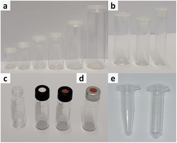
Generally, different influencing factors have to be considered when dealing with the sampling for easily evaporable liquids, thus, a short overview of the different configuration options for sample vessels is provided with respect to volume, material and capping options of the respective vessels.Another important factor is the choice of material. The most common materials chosen for production of vessels are either polypropylene (Fig. 1e) or glass (Fig. 1a–d). Depending on the conducted experiments this choice might change due to chemical incompatibilities or other necessities. However, for most experiments, glass vials are the best option as the material is chemical inert, stable to a range of temperatures and vials are available in a great range of volumes.
Considering all previously stated arguments, the best choice for sampling are 2 mL glass vials with, if required, a screw top lid containing a septum. Hence, this combination was chosen for further investigation.
Test for the requirement of sealing
After a first determination of the most suited vial option, further investigations were performed regarding the necessity for closing the vial during sampling and the best lid option. The available different sealing options are shown in Fig. 2 and comprise of either an unsealed vial or a vial sealed with a septum cap.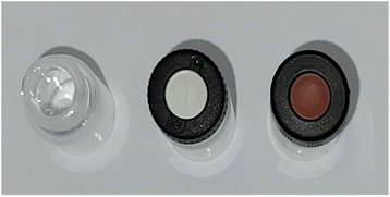 | ||
| Fig. 2 Overview of sealing options for the subsequent experiments. Left: unsealed vial. Middle: vial with slit septum lid. Right: vial with regular septum lid. | ||
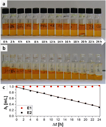
The easiest way to sample would be to use an unsealed vial as the omission of a cap is economically as well as ecologically advantageous. However, it is probable that for easily evaporable substances evaporation occurs which could change the sample composition. To test the hypothesis of sample evaporation from open vials in the first place, a simple evaporation test was performed with a solution of a dye in a low boiling solvent (bromophenol blue in methanol (boiling point: 65 °C (ref. 32))). Two experimental rows (E1 and E2) were conducted. For E1 the vials were capped with a septum cap, while for E2 no sealing was performed. The results of the experiments are shown in Fig. 3. The degree of filling for the two experiments varies significantly over time. For E1 no evaporation occurs. The filling level of the vials stays nearly constant in the range of accuracy of the robotic liquid dispensing system and is not dependent on the time of filling. This can be seen, as the filling height of the sample taken in the beginning (24 h elapsed between picture and filling) (E1/24 h) is the same as for the sample taken after 24 h (E1/0 h). For E2, however, a steady decrease can be observed from 100% filling height (1 mL) for E2/0 h to the primarily filled sample E2/24 h where only about 0.29 mL remain inside the vial. This linear decrease is also visible in the plot (Fig. 3c). With the data from the plot, an empirical evaporation rate for methanol in this context can be determined according to the slope of the linear fit in Fig. 3c, which is:
| hf = 0.989 mL − 0.028 mL h−1·Δt |
Hence, the evaporation rate of methanol for this experiment is 28 μL h−1. According to this information, 1 mL of methanol would evaporate in ca. 36 h in an open standard autosampler vial under the given conditions. If methanol (1 mL) is used as standard substance and a sample is automatically drawn by the parallel synthesizer at 8 p.m., the result of the quantitative measurement, performed at the next day, when the researcher appears in the laboratory at 8 a.m., will already be flawed by approximately 34%. In summary it is obvious that evaporation occurs in parallel synthesizers when sampling vials are left open for low to medium boiling substances. As evaporation did not occur for the samples stored in capped vials as obvious from samples E1/0 h to E1/24 h, those should be used for sampling instead.
Dependence of evaporation on vapor pressure of liquid
An influential factor for the evaporation of liquids is the vapor pressure of the substance. To claim the best sampling practice, it is important to monitor the sampling over a larger area of different liquids with differing vapor pressures. Hence, the evaporation behavior of six common liquids with a vapor pressure difference at 20 °C of ca. 580 mbar was investigated. The chemicals with their respective vapor pressures and experimentally determined evaporation rates are shown in Table 1.| Experiment number | Liquid | Vapor pressure @ 20 °C [mbar] | Evaporation rate [mL h−1] | |
|---|---|---|---|---|
| Open vial o | Sealed vial s | |||
| L1 | Dimethylformamide | 5.33![[thin space (1/6-em)]](https://www.rsc.org/images/entities/char_2009.gif) 33 33 |
0 | 0 |
| L2 | Water | 23.38![[thin space (1/6-em)]](https://www.rsc.org/images/entities/char_2009.gif) 34 34 |
0 | 0 |
| L3 | Methanol | 130.11![[thin space (1/6-em)]](https://www.rsc.org/images/entities/char_2009.gif) 35 35 |
−0.034 | 0 |
| L4 | Acetone | 246.38![[thin space (1/6-em)]](https://www.rsc.org/images/entities/char_2009.gif) 36 36 |
−0.081 | 0 |
| L5 | Dichloromethane | 481.29![[thin space (1/6-em)]](https://www.rsc.org/images/entities/char_2009.gif) 37 37 |
−0.166 | −0.005 |
| L6 | Diethyl ether | 583.55![[thin space (1/6-em)]](https://www.rsc.org/images/entities/char_2009.gif) 38 38 |
−0.500 | −0.015 |
For the experiment a similar setup was utilized as for the experiment of the requirement of sealing. The only difference being the storage of the liquids before the filling of the sampling vials.
The figures with an overview of the vials and the results of the evaporation experiments and plots of the evaporation rates are presented in the ESI (Fig. S3–S8†).
As visible from Table 1, overall evaporation in the investigated system can firstly be monitored above vapor pressures of 130 mbar. For lower evaporating liquids like dimethyl formamide (L1) or water (L2), no evaporation can be observed in neither case (open or sealed vial) during the time of observation (24 h). For more facile evaporating substances like methanol or acetone with vapor pressures above 130 or 200 mbar, evaporation can be observed from the unsealed vials L3o and L4o with rates between 34 to 81 μL h−1. This would correspond to total evaporation times of 1 mL of sample between ca. 30 (L3) and 12 hours (L4). In this range of vapor pressures, however, the sealed vials L3s and L4s show no evaporation and, hence, keep their initial composition over a time of at least 24 h. With further increasing vapor pressure, the challenge of absolute retention becomes greater. As the system using a slit septum lid is only semi-closed, increasing build-up pressures inside the vial due to evaporation of the liquid in the vial's headspace are able to be released. This can be observed for dichloromethane (L5) and diethyl ether (L6). For both, in case of the unsealed vials, total evaporation occurred within 24 h. For L6o total evaporation already occurred after 2 h, while for L5o the same was the case after ca. 6 h. For the sealed vials, as well, evaporation could be observed. However, the rates of evaporation were decreased significantly compared to the unsealed vials. The decreasing factor, determined by dividing the evaporation rate for the open vial by the rate obtained for the closed vial is ca. 33, which would mean that a sample which evaporates within one hour in an opened vial would need notably more time (33 h) to evaporate completely from a sealed vial under similar circumstances.
Generally, it is obvious that with increasing vapor pressures, the task of sealing is getting more difficult and deviations between the initial composition at the time of sampling and the time of measurement become more probable. For liquids below the vapor pressure of water, no visible advantage could be found for the proposed method as no evaporation occurs even from the unsealed vials (during the observed time frame of 24 h). However, a lot of used chemicals, e.g., monomers in polymerizations or solvents, have vapor pressures above the ones of the mentioned substances.39,40 Hence, the area of higher vapor pressures is of greater interest. With increasing vapor pressure, the proposed method shows its advantages in comparison to the classic use of unsealed vials. The rate of evaporation decreases significantly when using sealed vials which, in turn, leads to a better retention of the sample's properties between the time of sampling and the time of measuring.
Dependence of evaporation on external factors
Besides the previously investigated parameters, the evaporation from open and closed vials is dependent on further factors. The first group are environmental factors, like humidity or surrounding temperature. These are dependent on the setup used and the experimental approach. In the used experimental setup, the heat radiated from the reactors in close proximity to the sampling racks plays a vital role. E.g., for water the evaporation will be faster if the temperature is increased or the surrounding relative humidity is decreased.41 In this experiment, the values for the temperature, measured close to the sampling rack, reached values of up to 29.3 °C at the end of the interval of 24 h. The relative humidity, in turn, decreased by ca. 8% from 44.3% to 36.5% over the course of the experiment. Differences in these temperatures and humidities will definitely affect the evaporation of samples taken in non-sealed vials. For sealed vials, the influence will be smaller as the system is semi-closed. However, in general, the changes in temperature or humidity inside the automated platform will not be large but rather small, even with higher heating temperatures of the reactors. Hence, the assumptions taken from the evaluation of the conducted experiments are generalizable.Additional influential factors could be the specifications of the needle. In the case of the performed experiments, a septum piercing needle with an outer diameter of 1.5 mm was utilized. This will, in turn, lead to a small puncture through the septum material and low exchange between the atmosphere in the vial and outside it as the physical barrier remains intact. With larger needle diameters the lid material could be pierced in a way that the material is irrecoverably damaged. The resulting holes would then lead to easier evaporation. Therefore, it is recommended to take the needle with the smallest applicable diameter.
Furthermore, the surface area will play an important role for evaporation. The higher the area, the larger also the evaporation tendency.42 However, as previously mentioned, the best choice are small (2 mL) vials which in turn always have the same surface area. Hence, this point will not be investigated in detail in this study.
Comparison of sealing options
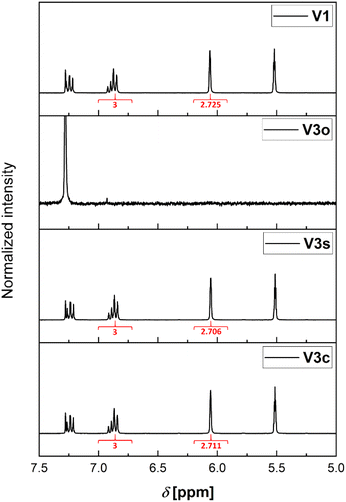
As mentioned earlier, there are two different available septum types (see Fig. 2). The first consists of a silicone/PTFE septum with a slit in its center. The second option is the usage of an unslitted rubber/PTFE septum. In the following, a detailed comparison for their application is provided.| Sample condition | Experiment | Integral for MMA methylene protonsa | Retention of ratio [%] |
|---|---|---|---|
| a Integral of the peak at δ = 5.52 ppm determined compared to the integral (3) of the ortho and para anisole protons (δ = 6.75 to 6.95 ppm). b Complete evaporation of the sample. Hence, no integral and no retention measurable. | |||
| Reference sample | V1 | 2.725 | 100 |
| Open vial, no D-chloroform addition | V2o | —b | —b |
| Open vial, D-chloroform addition | V3o | —b | —b |
| Regular septum lid, no D-chloroform addition | V2c | 0.735 | 27 |
| Regular septum lid, D-chloroform addition | V3c | 2.711 | 100 |
| Slit septum lid, D-chloroform addition | V2s | 0.181 | 7 |
| Regular septum lid, no D-chloroform addition | V3s | 2.706 | 100 |
This effect is more pronounced for the combination with the slitted septum. However, both combinations without prefilled solvent cannot be used for an error-free sampling strategy. Hence, it is required to store the samples prior to analysis mixed with a larger volume of solvent or quenching agent as otherwise the changes in the ratio of the components of the sample are severe.
This data is also in accordance with the conducted sampling experiment for GC measurements. The data for this experiment (V4, V5) can be found in the electronical ESI (Table S1†) of this article.
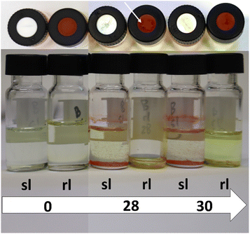
As it can be seen from the mentioned figures, no direct correlation can be obtained between the number of punctures and the evaporation tendency of the liquid inside the vial. The evaporation seems to be almost identical for most of the vials for both of the sealing possibilities. This is particularly evident for the experiment with methanol P1 (Fig. S22†). In this case, all vials are filled to the same level after the experiment, regardless of the number of punctures or the lid type itself. For P2 (Fig. S23†), however, smaller differences are visible. Nonetheless, there does not seem to be a clear tendency which sealing type works better. For the samples with zero punctures, the regular sealing lid retains more liquid. This is consistent with expectations, as the slit in the septum dissipates the excess pressure which builds up for liquids with high vapor pressure (dichloromethane in this case) under the experimental conditions. The regular septum lid does not provide this capability, which is why it performs better (see Fig. 5). For the samples with ten, 14, 22 and 28 punctures, the slit septum cap seems to be the better choice as it retains more liquid. For the other puncture numbers, there is not much difference. As the difference is very pronounced for the samples with 28 punctures, these were investigated further and are shown in comparison with the samples with zero and 30 punctures in Fig. 5. For the vials with 28 punctures (P2/rl/28; P2/sl/28) through the lid, it can be seen that the lid of the vial sealed with a regular rubber septum lid (P2/rl/28), was damaged to such an extent that a crack formed, resulting in total evaporation of the dichloromethane. Since this phenomenon did not occur for P2/rl/30, it can be assumed that the number of punctures is less important than the location of the recurring punctures. This depends on the accuracy of the placement of the needles within the automated platform and varies depending on the calibration state of the X- and Y-axis of the platform and the platform itself. The slit septum lid has an advantage in this regard, as the pre-existing slit provides a “guide” for the needle. The regular rubber septum does not offer this possibility. Therefore, it is more likely to be punctured at different locations. This can cause a tear to form in the septum since the following punctures are close to the previous puncture. Should such a tear occur, it will result in faster evaporation of liquids from the vial sealed with a regular rubber septum lid. However, the occurrence of such a crack seems to be at least partially random, as shown by the comparison of P2/rl/28 and P2/rl/30.
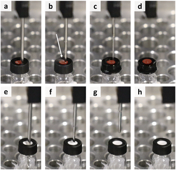 | ||
| Fig. 6 Overview of the needle retraction process for the vials with regular rubber septum (a–d) and slitted rubber septum (e–h) at the same steps in the process. | ||
Another option is to use caps with a slitted septum as they possess the ability to release the excess pressure before the sampling can get affected (Fig. 6e–h). Furthermore, excessive evaporation is also avoided. Moreover, in this manner no human intervention is required, which maintains the advantage of automated platforms to work without manual intervention.
Practical consideration for sampling – downholding
At this point, the best sampling practice seemed to be determined by utilizing a 2 mL glass autosampler vial with a screw-on slitted septum lid. However, when applying the sampling method in the automated parallel synthesizer, another challenge arose. As shown in Fig. 7, withdrawing the needle from the vial caused the vial to be pulled out of the sample rack. As tested, this occurs regardless of the caps used. This pulling up of the vial results in loss of the vial within the robotic platform, as stripping the vial from the 4-needle head (Fig. 7c) causes the vial to fall at undefined places in the robot. A video of this process can be accessed via the ESI (VSI2†). This challenge could be overcome by utilizing fused deposition modelling 3D-printing. Therefore, a module to hold down the vial was designed (design files available in the ESI (DSI1–DSI3†)), printed, and tested in the context of applying counter-pressure onto the vial. The module applied on top of a sample rack with four vials is represented in Fig. 7d and e. A video of the module put into work (VSI3) as well as a video of the module with integrated vials on top of a sampling rack are part of the ESI (VSI4†). The module was able to keep the vials in place during the sampling process and was, therefore, applied for subsequent experiments.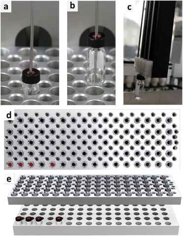 | ||
| Fig. 7 Representation of a vial, withdrawn with the needle of the 4-needle head (a–c) and representation of the developed downholding module in top view (d) and orthogonal view (e). | ||
Final sampling practice
The finally applied and recommended sampling strategy is the utilization of a prefilled 2 mL glass autosampler sampling vial with a slit septum cap to avoid ratio change. Furthermore, a module for downholding of the vial during the sampling process should be applied. With this method, a reproducible sampling can be achieved. Furthermore, this method can be utilized also for highly volatile substances to reach less evaporation from the vial. The method is easily scalable as only the number of vials needs to be increased and more downholding modules need to be manufactured. This is fairly easy as filament 3D-printing nowadays is a standard method in laboratories and hobbyists workshops.Experimental
Materials and methods
Methyl methacrylate was purchased from Sigma-Aldrich in 99% purity. Bromophenol blue was purchased from Merck. Chloroform was purchased in HPLC-grade from VWR. Deuterated chloroform was purchased from Eurisotop. Dimethylformamide (>99.9%), acetone (>99%), dichloromethane (98%) and diethyl ether (technical grade) were purchased from VWR chemicals. Methanol (>95%) was purchased from Thermo Fisher Scientific. Water was taken as tab water from the laboratories fresh water system.Humidity and temperature in the sampling rack were measured with a Lufft OPUS20 TCO.
1H NMR spectra were recorded on a Bruker Avance I spectrometer (300 MHz) at 298 K. The chemical shifts are given in parts per million (ppm on δ scale) related to the deuterated solvent.
GC measurements were performed on the following system:
Shimadzu GC-2010 with an FID (detector), Carl Roth, Roti®Cap-5 MS (30 m long, 0.25 mm ID, 0.25 μm film thickness) (column) with a stationary phase consisting of (5% diphenyl) 95% dimethyl polysiloxane and helium as carrier gas. The samples were prepared in chloroform as solvent.
All experiments/tests were conducted utilizing a Chemspeed Accelerator SLT 106 automated parallel synthesizer platform. The synthesizer was equipped with a 4-needle head for liquid transfers with connected 10 mL tubing and syringes, one reactor block consisting of 16 individual reactor vessels (13 mL) with heating mantles and a sample rack (double level holder, purchased from Chemspeed). The reactor block was topped up with a reflux module consisting of individual hollow glass fingers and a controlling module to open and close the reactors. Heating to 70 °C was supplied by an external heating circuit with a Huber Unistat Tango as a dynamic temperature control system. The reflux coolers were flowed through with a mixture of ethylene glycol and water (volumes = 1![[thin space (1/6-em)]](https://www.rsc.org/images/entities/char_2009.gif) :
:![[thin space (1/6-em)]](https://www.rsc.org/images/entities/char_2009.gif) 5) to apply a constant cooling of the fingers to 5 °C. In this case a Lauda Microcool MC 600 was utilized as temperature control system. The platform is shown in Fig. 8.
5) to apply a constant cooling of the fingers to 5 °C. In this case a Lauda Microcool MC 600 was utilized as temperature control system. The platform is shown in Fig. 8.
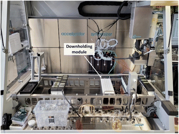 | ||
| Fig. 8 Overview of the robotic platform with 4-needle head (right), syringe pumps (middle) as well as sample rack with white downholding module and reactor block (middle right). | ||
The downholding module was designed in Autodesk Inventor Professional 2020 and printed on a Prusa i3 MK3S fused deposition modelling 3D-printer with polylactic acid (PLA) Filament (PrimaValue PLA, different colours, diameter = 1.75 mm) (GCode available as DSI3†).
Test for the requirement of sealing
The previously described synthesis platform was utilized. Four of the reactors were filled with 10 mL of bromophenol blue (BPB) in methanol (c = 2.99 mmol L−1). The solutions were heated to 70 °C and mixed via vortex-shaking at 400 rpm. The vials with a septum cap (E1) and without a lid (E2) were placed in a sample rack in a distance of about 11 cm from the reactors (see Fig. S2†) for 24 h. Every second hour 1 mL of sample was taken with the automated liquid handling system from two of the reactors and filled into the respective vials at the same time. After 24 h, the sampling rack was removed from the synthesizer and the filling level of each vial was documented.Dependence on vapor pressure of liquid
The previously described synthesis platform was utilized. Two 100 mL vials were filled each with 75 mL of a solution of a solvent with 20 to 25 mg of BPB. For each solvent sampling vials with septum caps (e.g., L1s) and without a lid (e.g., L1o) were placed in a sampling rack about 11 cm from the reactors. Then, the reactors were heated to 70 °C at a vortex-shaking rate of 400 rpm. Every second hour 1 mL of sample per sampling vial was taken with the automated liquid handling system from the 100 mL stock vials and dispensed into the sampling vials. After 24 h the sampling rack was removed from the synthesizer and the filling level of each vial was documented.Comparison of sealing options
Choice of sealing option. Three standard 2 mL glass autosampler screw cap vials (surface area: ca. 0.66 cm2) were placed inside a sampling rack. One of them was left unsealed, one was capped with a regular rubber septum cap and the last with a slit septum cap. To avoid retraction of the vials due to friction between the needle and the septum, the vials were wedged with paper into the respective well of the sample rack. Afterwards, 0.1 mL of chloroform was inserted to the vials using a septum-piercing needle with an outer diameter of 1.5 mm and a waiting time of approximately ten minutes was applied. Subsequently, 1 mL of chloroform was injected to the vials via the 4-needle head of the automated parallel synthesizer (Chemspeed SLT 100). After the injection, the needle was retracted from the vial.
Conclusions
High-throughput experimentation is important for the ongoing digitization of material sciences and chemistry in order to obtain reliable data for artificial intelligence and machine learning approaches. A special emphasis in this field should lie on the sampling process as this presents a crucial step and can affect the reaction data in a significant manner. In particular, quantitative sampling is a challenge in automated parallel synthesizers as evaporation from open vials can change the composition of a sample. To enhance this part of the automated process, we developed a new method for quantitative sampling. Hence, several options regarding the choice of the ideal sampling vessel as well as sealing option were discussed and investigated with regard to their suitability for sampling of easily evaporating substances. It was found that sealing of the sampling vials, in contrast to the current state-of-the-art, is of utmost importance to avoid complete or partial evaporation of the sample. For partial evaporation over time, it could be shown that the ratio of a particular monomer (MMA) changes with respect to a standard (anisole). Hence, sampling should be performed with prefilled quenching agents or solvents. The ideal sealing option for sampling could be found in a 2 mL autosampler glass vial with a slitted septum due to its ability to release any excess pressure that occurs during injection of the sample into the vial. Finally, the use of a counter-pressure module was found to prevent the vial from being withdrawn from the sampling rack.Therefore, it was possible to establish a new best practice for automated sampling for various analytical methods such as GC or SEC in automated parallel synthesizers. These findings will significantly improve the possibilities for representative quantitative sampling in synthesis robots and, therefore, open the possibility to generate more reliable data for the use with artificial intelligence methods which will foster the understanding of quantitative structure–property relationships.
The design files for the downholding module as well as the G-Code for 3D printing on a Prusa i3MK3S with polylactic acid filament can be found in the ESI (DSI1–DSI3†). 1H-NMR as well as GC primary data can be obtained on request from the authors, the processed spectra are shown in the ESI.†
Data availability
The data, pictures, videos and design files supporting this article have been uploaded as part of the ESI.† Further raw data can be obtained by the authors on request.Author contributions
Conceptualization: M. R. and S. Z.; investigation and data curation: M. R.; design of module: M. R. and T. S.; writing – original draft: M. R.; writing – review and editing: M. R., T. S., S. Z. and U. S. S.; supervision: S. Z. and U. S. S.; resources: U. S. S.; project administration: U. S. S.; funding acquisition: U. S. S. All authors have read and agreed to the published version of the manuscript.Conflicts of interest
There are no conflicts to declare.Acknowledgements
The authors thank the “Deutsche Forschungsgemeinschaft” for funding under the regime of the priority programme SPP 2363 “Utilization and Development of Machine Learning for Molecular Applications – Molecular Machine Learning” (SCHU 1229/63-1; project number 497115849). Furthermore, Patrick Endres and Dr Grit Festag are acknowledged for help with the GC-equipment.References
- J. Kimmig, S. Zechel and U. S. Schubert, Digital transformation in materials science: A paradigm change in material's development, Adv. Mater., 2021, 33, e2004940, DOI:10.1002/adma.202004940.
- L. Himanen, A. Geurts, A. S. Foster and P. Rinke, Data-driven materials science: Status, challenges, and perspectives, Adv. Sci., 2019, 6, 1900808, DOI:10.1002/advs.201900808.
- B. Burger, P. M. Maffettone, V. V. Gusev, C. M. Aitchison, Y. Bai, X. Wang, X. Li, B. M. Alston, B. Li, R. Clowes, N. Rankin, B. Harris, R. S. Sprick and A. I. Cooper, A mobile robotic chemist, Nature, 2020, 583, 237–241, DOI:10.1038/s41586-020-2442-2.
- E. O. Pyzer-Knapp, J. W. Pitera, P. W. J. Staar, S. Takeda, T. Laino, D. P. Sanders, J. Sexton, J. R. Smith and A. Curioni, Accelerating materials discovery using artificial intelligence, high performance computing and robotics, npj Comput. Mater., 2022, 8, 1–9, DOI:10.1038/s41524-022-00765-z.
- K. T. Butler, D. W. Davies, H. Cartwright, O. Isayev and A. Walsh, Machine learning for molecular and materials science, Nature, 2018, 559, 547–555, DOI:10.1038/s41586-018-0337-2.
- C. Guerrero-Sanchez, L. O'Brien, C. Brackley, D. J. Keddie, S. Saubern and J. Chiefari, Quasi-block copolymer libraries on demand via sequential RAFT polymerization in an automated parallel synthesizer, Polym. Chem., 2013, 4, 1857–1862, 10.1039/c3py21135e.
- C. Guerrero-Sanchez, C. Abeln and U. S. Schubert, Automated parallel anionic polymerizations: Enhancing the possibilities of a widely used technique in polymer synthesis, J. Polym. Sci., Part A: Polym. Chem., 2005, 43, 4151–4160, DOI:10.1002/pola.20887.
- M. A. Gallop, R. W. Barrett, W. J. Dower, S. P. Fodor and E. M. Gordon, Applications of combinatorial technologies to drug discovery. 1. Background and peptide combinatorial libraries, J. Med. Chem., 1994, 37, 1233–1251, DOI:10.1021/jm00035a001.
- S. Brocchini, K. James, V. Tangpasuthadol and J. Kohn, A combinatorial approach for polymer design, J. Am. Chem. Soc., 1997, 119, 4553–4554, DOI:10.1021/ja970389z.
- S. Schmatloch, H. Bach, R. A. T. M. van Benthem and U. S. Schubert, High-throughput experimentation in organic coating and thin film research: State-of-the-art and future perspectives, Macromol. Rapid Commun., 2004, 25, 95–107, DOI:10.1002/marc.200300146.
- M. W. M. Fijten, M. A. R. Meier, R. Hoogenboom and U. S. Schubert, Automated parallel investigations/optimizations of the reversible addition-fragmentation chain transfer polymerization of methyl methacrylate, J. Polym. Sci., Part A: Polym. Chem., 2004, 42, 5775–5783, DOI:10.1002/pola.20346.
- A. C. Cooper, L. H. McAlexander, D.-H. Lee, M. T. Torres and R. H. Crabtree, Reactive dyes as a method for rapid screening of homogeneous catalysts, J. Am. Chem. Soc., 1998, 120, 9971–9972, DOI:10.1021/ja9818607.
- A. Holzwarth, H.-W. Schmidt and W. F. Maier, Detection of catalytic activity in combinatorial libraries of heterogeneous catalysts by IR thermography, Angew. Chem., Int. Ed., 1998, 37, 2644–2647, DOI:10.1002/(SICI)1521-3773(19981016)37:19<2644::AID-ANIE2644>3.0.CO;2-%23.
- E. J. Kluender, J. L. Hedrick, K. A. Brown, R. Rao, B. Meckes, J. S. Du, L. M. Moreau, B. Maruyama and C. A. Mirkin, Catalyst discovery through megalibraries of nanomaterials, Proc. Natl. Acad. Sci. U. S. A., 2019, 116, 40–45, DOI:10.1073/pnas.1815358116.
- S. V. Ley, D. E. Fitzpatrick, R. J. Ingham and R. M. Myers, Organic synthesis: March of the machines, Angew. Chem., Int. Ed., 2015, 54, 3449–3464, DOI:10.1002/anie.201410744.
- E. J. Roberts, S. E. Habas, L. Wang, D. A. Ruddy, E. A. White, F. G. Baddour, M. B. Griffin, J. A. Schaidle, N. Malmstadt and R. L. Brutchey, High-throughput continuous flow synthesis of nickel nanoparticles for the catalytic hydrodeoxygenation of guaiacol, ACS Sustainable Chem. Eng., 2017, 5, 632–639, DOI:10.1021/acssuschemeng.6b02009.
- S. Chatterjee, M. Guidi, P. H. Seeberger and K. Gilmore, Automated radial synthesis of organic molecules, Nature, 2020, 579, 379–384, DOI:10.1038/s41586-020-2083-5.
- R. Hoogenboom, M. W. M. Fijten, M. A. R. Meier and U. S. Schubert, Living cationic polymerizations utilizing an automated synthesizer: High-throughput synthesis of polyoxazolines, Macromol. Rapid Commun., 2003, 24, 92–97, DOI:10.1002/marc.200390003.
- C. R. Becer, A. M. Groth, R. Hoogenboom, R. M. Paulus and U. S. Schubert, Protocol for automated kinetic investigation/optimization of the RAFT polymerization of various monomers, QSAR Comb. Sci., 2008, 27, 977–983, DOI:10.1002/qsar.200720159.
- R. J. Kleijwegt, S. Y. Doruiter, W. Winkenwerder and J. van der Schaaf, Investigating tertiary amine alkylation/benzylation kinetics with ramp-flow in a plug-flow reactor using in-line 1H NMR spectroscopy, Chem. Eng. Res. Des., 2021, 168, 317–326, DOI:10.1016/j.cherd.2021.02.021.
- C. F. Carter, H. Lange, S. V. Ley, I. R. Baxendale, B. Wittkamp, J. G. Goode and N. L. Gaunt, ReactIR flow cell: A new analytical tool for continuous flow chemical processing, Org. Process Res. Dev., 2010, 14, 393–404, DOI:10.1021/op900305v.
- K. A. Farley, U. Reilly, D. P. Anderson, B. P. Boscoe, M. W. Bundesmann, D. A. Foley, M. S. Lall, C. Li, M. R. Reese and J. Yan, Utilizing on- and off-line monitoring tools to follow a kinetic resolution step during flow synthesis, Magn. Reson. Chem., 2017, 55, 348–354, DOI:10.1002/mrc.4494.
- C. J. Welch, X. Gong, J. Cuff, S. Dolman, J. Nyrop, F. Lin and H. Rogers, Online analysis of flowing streams using microflow HPLC, Org. Process Res. Dev., 2009, 13, 1022–1025, DOI:10.1021/op9001017.
- F. H. Florenzano, R. Strelitzki and W. F. Reed, Absolute, on-line monitoring of molar mass during polymerization reactions, Macromolecules, 1998, 31, 7226–7238, DOI:10.1021/ma980876e.
- M. A. Morin, W. Zhang, D. Mallik and M. G. Organ, Sampling and analysis in flow: The keys to smarter, more controllable, and sustainable fine-chemical manufacturing, Angew. Chem., Int. Ed., 2021, 133, 20774–20794, DOI:10.1002/ange.202102009.
- M. Rubens, J. van Herck and T. Junkers, Automated polymer synthesis platform for integrated conversion targeting based on inline benchtop NMR, ACS Macro Lett., 2019, 8, 1437–1441, DOI:10.1021/acsmacrolett.9b00767.
- J. van Herck, I. Abeysekera, A.-L. Buckinx, K. Cai, J. Hooker, K. Thakur, E. van de Reydt, P.-J. Voorter, D. Wyers and T. Junkers, Operator-independent high-throughput polymerization screening based on automated inline NMR and online SEC, Digital Discovery, 2022, 1, 519–526, 10.1039/D2DD00035K.
- S. T. Knox, S. J. Parkinson, C. Y. P. Wilding, R. A. Bourne and N. J. Warren, Autonomous polymer synthesis delivered by multi-objective closed-loop optimisation, Polym. Chem., 2022, 13, 1576–1585, 10.1039/D2PY00040G.
- C. Guerrero-Sanchez, S. Harrisson and D. J. Keddie, High-throughput method for RAFT kinetic investigations and estimation of reactivity ratios in copolymerization systems, Macromol. Symp., 2013, 325–326, 38–46, DOI:10.1002/masy.201200038.
- R. Hoogenboom, M. W. M. Fijten, C. H. Abeln and U. S. Schubert, High-throughput investigation of polymerization kinetics by online monitoring of GPC and GC, Macromol. Rapid Commun., 2004, 25, 237–242, DOI:10.1002/marc.200300218.
- M. Christensen, F. Adedeji, S. Grosser, K. Zawatzky, Y. Ji, J. Liu, J. A. Jurica, J. R. Naber and J. E. Hein, Development of an automated kinetic profiling system with online HPLC for reaction optimization, React. Chem. Eng., 2019, 4, 1555–1558, 10.1039/C9RE00086K.
- J. E. Lucius, G. R. Olhoeft, P. L. Hill and S. K. Duke, Properties and hazards of 108 selected substances, Open-File Report, 1992 Search PubMed.
- J. A. Young and N. N-Dimethylformamide, J. Chem. Educ., 2004, 81, 632, DOI:10.1021/ed081p632.
- A. Wexler, Vapor pressure formulation for water in range 0 to 100 °C. A revision, J. Res. Natl. Bur. Stand., Sect. A, 1976, 80A, 775–785, DOI:10.6028/jres.080A.071.
- H. F. Gibbard and J. L. Creek, Vapor pressure of methanol from 288.15 to 337.65.deg.K, J. Chem. Eng. Data, 1974, 19, 308–310, DOI:10.1021/je60063a013.
- E. C. Baughan, A. L. Jones and K. Stewart, The absorption of organic vapours by thin films of nitrocellulose, Proc. R. Soc. London, Ser. A, 1954, 225, 478–504, DOI:10.1098/rspa.1954.0217.
- J. A. Young, Dichloromethane, J. Chem. Educ., 2004, 81, 1415, DOI:10.1021/ed081p1415.
- DDBST GmbH, Vapor pressure of diethyl ether, http://www.ddbst.com/en/EED/PCP/VAP_C12.php, accessed 29 June 2023.
- L. Lomba, B. Giner, C. Lafuente, S. Martín and H. Artigas, Thermophysical properties of three compounds from the acrylate family, J. Chem. Eng. Data, 2013, 58, 1193–1202, DOI:10.1021/je301333b.
- DDBST GmbH, Vapor pressure of tetrahydrofuran, http://www.ddbst.com/en/EED/PCP/VAP_C159.php, accessed 29 June 2023.
- T. Ozturk and H. Y. Erbil, Evaporation of water-ethanol binary sessile drop on fluoropolymer surfaces: Influence of relative humidity, Colloids Surf., A, 2018, 553, 327–336, DOI:10.1016/j.colsurfa.2018.05.076.
- K. Kim, S. Yu, C. An, S.-W. Kim and J.-H. Jang, Mesoporous three-dimensional graphene networks for highly efficient solar desalination under 1 sun illumination, ACS Appl. Mater. Interfaces, 2018, 10, 15602–15608, DOI:10.1021/acsami.7b19584.
Footnote |
| † Electronic supplementary information (ESI) available: 3D models and GCode of module: DSI. Videos of certain stages of the process: VSI (linked in the text). Setup of the evaporation experiments, overviews for evaporation experiments with different liquids, GC retention experiment and different views of the downholding module with dimensions. NMR and GC spectra figures. See DOI: https://doi.org/10.1039/d3dd00074e |
| This journal is © The Royal Society of Chemistry 2023 |

