 Open Access Article
Mechanical properties and peculiarities of molecular crystals
Wegood M.
Awad
 a,
Daniel W.
Davies
 b,
Daichi
Kitagawa
 c,
Jad
Mahmoud Halabi
 a,
Marieh B.
Al-Handawi
 a,
Ibrahim
Tahir
 a,
Fei
Tong
 d,
Gonzalo
Campillo-Alvarado
 b,
Alexander G.
Shtukenberg
 e,
Tamador
Alkhidir
fp,
Yuki
Hagiwara
 o,
Mubarak
Almehairbi
fp,
Linfeng
Lan
 h,
Shodai
Hasebe
 o,
Durga Prasad
Karothu
 am,
Sharmarke
Mohamed
 *fp,
Hideko
Koshima
 *g,
Seiya
Kobatake
 *c,
Ying
Diao
 *b,
Rajadurai
Chandrasekar
 *i,
Hongyu
Zhang
 *h,
Changquan Calvin
Sun
 *j,
Christopher
Bardeen
 *k,
Rabih O.
Al-Kaysi
 *l,
Bart
Kahr
 *e and
Panče
Naumov
 *aemn
*aemn
aSmart Materials Lab, New York University Abu Dhabi, PO Box 129188, Abu Dhabi, United Arab Emirates. E-mail: pn21@nyu.edu
bDepartment of Chemical and Biomolecular Engineering, University of Illinois at Urbana-Champaign, 600 S. Mathews Ave., Urbana, IL 61801, USA
cDepartment of Chemistry and Bioengineering, Graduate School of Engineering, Osaka Metropolitan University, 3-3-138 Sugimoto, Sumiyoshi-ku, Osaka 558-8585, Japan
dKey Laboratory for Advanced Materials and Joint International Research Laboratory of Precision Chemistry and Molecular Engineering, Feringa Nobel Prize Scientist Joint Research Center, Frontiers Science Center for Materiobiology and Dynamic Chemistry, Institute of Fine Chemicals, School of Chemistry and Molecular Engineering, East China University of Science and Technology, Shanghai, China
eDepartment of Chemistry/Molecular Design Institute, New York University, New York, USA
fDepartment of Chemistry, Green Chemistry & Materials Modelling Laboratory, Khalifa University of Science and Technology, Abu Dhabi, United Arab Emirates
gResearch Organization for Nano and Life Innovation, Waseda University, Tokyo, Japan
hState Key Laboratory of Supramolecular Structure and Materials, Jilin University, 2699 Qianjin Street, Changchun 130012, China
iAdvanced Organic Photonic Materials and Technology Laboratory at School of Chemistry, University of Hyderabad, Hyderabad, India
jPharmaceutical Materials Science and Engineering Laboratory, Department of Pharmaceutics, College of Pharmacy, University of Minnesota, Minneapolis, Minnesota, USA
kDepartment of Chemistry, University of California Riverside, 501 Big Springs Road, Riverside, CA, USA
lCollege of Science and Health Professions, King Saud Bin Abdulaziz University for Health Sciences (KSAU-HS) & King Abdullah International Medical Research Center (KAIMRC), Ministry of National Guard Health Affairs, Riyadh, Kingdom of Saudi Arabia
mCenter for Smart Engineering Materials, New York University Abu Dhabi, PO Box 129188, Abu Dhabi, United Arab Emirates
nResearch Center for Environment and Materials, Macedonian Academy of Sciences and Arts, Bul. Krste Misirkov 2, MK−1000 Skopje, Macedonia
oGraduate School of Advanced Science and Engineering, Waseda University, Tokyo, Japan
pAdvanced Materials Chemistry Center (AMCC), Khalifa University of Science and Technology, PO Box 127788, Abu Dhabi, United Arab Emirates
First published on 18th April 2023
Abstract
In the last century, molecular crystals functioned predominantly as a means for determining the molecular structures via X-ray diffraction, albeit as the century came to a close the response of molecular crystals to electric, magnetic, and light fields revealed that the physical properties of molecular crystals were as rich as the diversity of molecules themselves. In this century, the mechanical properties of molecular crystals have continued to enhance our understanding of the colligative responses of weakly bound molecules to internal frustration and applied forces. Here, the authors review the main themes of research that have developed in recent decades, prefaced by an overview of the particular considerations that distinguish molecular crystals from traditional materials such as metals and ceramics. Many molecular crystals will deform themselves as they grow under some conditions. Whether they respond to intrinsic stress or external forces or interactions among the fields of growing crystals remains an open question. Photoreactivity in single crystals has been a leading theme in organic solid-state chemistry; however, the focus of research has been traditionally on reaction stereo- and regio-specificity. However, as light-induced chemistry builds stress in crystals anisotropically, all types of motions can be actuated. The correlation between photochemistry and the responses of single crystals—jumping, twisting, fracturing, delaminating, rocking, and rolling—has become a well-defined field of research in its own right: photomechanics. The advancement of our understanding requires theoretical and high-performance computations. Computational crystallography not only supports interpretations of mechanical responses, but predicts the responses itself. This requires the engagement of classical force-field based molecular dynamics simulations, density functional theory-based approaches, and the use of machine learning to divine patterns to which algorithms can be better suited than people. The integration of mechanics with the transport of electrons and photons is considered for practical applications in flexible organic electronics and photonics. Dynamic crystals that respond rapidly and reversibly to heat and light can function as switches and actuators. Progress in identifying efficient shape-shifting crystals is also discussed. Finally, the importance of mechanical properties to milling and tableting of pharmaceuticals in an industry still dominated by active ingredients composed of small molecule crystals is reviewed. A dearth of data on the strength, hardness, Young's modulus, and fracture toughness of molecular crystals underscores the need for refinement of measurement techniques and conceptual tools. The need for benchmark data is emphasized throughout.
1. Introduction to mechanical properties and effects in molecular crystals
1.1. General introduction to mechanical properties
Conventionally, there are two types of strength: yield strength and ultimate strength. Yield strength is the maximum stress at the yielding point after which a material will start to deform plastically. Typically, however, strength is used to refer to the maximum stress a material can sustain before weakening and eventually failing. If the stress continues to increase beyond the ultimate strength, the material will reach the breaking point. The energy per unit volume absorbed by the material up until that point is the toughness, commonly referred to as fracture toughness. While materials that are strong and tough—withstanding damage or fracturing—are generally sought after, the two properties are mutually exclusive.1 To achieve high toughness, a material must be able to undergo a controlled deformation to enable the dissipation of high stresses. Otherwise, these stresses will contribute to crack initiation and propagation, causing the material to fracture. This consideration explains why strong and rigid materials such as glass and ceramics are brittle while more ductile materials that deform more easily might not be as strong but tend to be tougher. Therefore, plasticity plays an important role in characterizing high-toughness materials where the plastic zone is extended making it resistant to cracking and bond breakage.1 Molecular crystals, for example, are generally characterized as brittle, meaning that they often fail through cleavage along crystallographic planes instead of allowing for dislocations to flow. When the movement of these dislocations is blocked, they pile up and create microcavities that then lead to crack growth.2 Recently, more examples of plasticity in molecular crystals have been reported, introducing new possibilities of investigating and optimizing higher toughness in these crystalline solids.3–6
Nascent examples of more compliant and soft molecular crystals provide an opportunity to utilize these conventionally fragile structures and complement the soft and predominantly amorphous organic polymers and elastomers. The more mechanically robust properties of molecular crystals also promise to resolve the issues of defect and fracture formation when subjected to moderate abrasion, compromising the advantageous long-range order and jeopardizing their unique optical, electrical, and magnetic properties. Low resistance to fatigue and wear is also commonly associated with poor cyclability, and may further pose difficulties in processing and integration in technological devices. For this reason, crystalline organic solids have largely remained in the purview of solid-state chemists, crystallographers, and crystal engineers. However, the recent burgeoning research into the responsive properties of adaptive organic molecular crystals has started to unveil hitherto unexplored and potentially useful dynamic aspects. New reports of unconventional mechanical compliance have prompted a comprehensive revalidation of molecular crystals as technologically applicable smart-material candidates.
Mechanical hardness is desirable in robust and sophisticated devices and machines. While definitions vary, hardness can be defined as a surface property in that it measures a material's resistance to permanent surface deformation, and is a highly characteristic property of a solid. The hardness reflects a materials’ resistance to wear and tear, which is essential in dynamic mechanical parts and in material design for mechanical actuators where positional accuracy that is otherwise lost in plastic deformation becomes relevant. It is no exaggeration to say that without the advances in hard and strong materials, the 19th century would not have witnessed an industrial revolution.7 More recently, soft materials such as polymers and elastomers have also gained attention in many technological applications, particularly in biotechnology, stimuli-responsive materials, nanotechnology, and robotics.8 For example, their low hardness and ease of deformation turn them into great candidates for safe robot–human interfaces.
Routine hardness tests are typically the simplest way to produce and measure irreversible deformation in a material.9 Hard indenter tips with predefined geometries and shapes are driven at a constant loading or displacement rate into a specimen surface.10 The shape of the tip can vary among different methods from a rhombohedron (Knoop) to a sphere (Brinell and Rockwell B or C), a square pyramid (Vickers), or a trigonal pyramid (Berkovich).7 The ratio of the applied force to the size of the indentation projection is the hardness number which is typically obtained on different scales depending on the indenter shape. This oftentimes makes it difficult to compare hardness tests obtained through different methods. Despite hardness often being considered as a measure of resistance to plastic deformation, it is rather a complex property. Hardness is usually treated as a measure of a material's resistance to penetration, spreading, or scratching which respectively yields quantitative information on elastic, plastic, or fracture properties.7 Evidently, the underlying mechanisms for these deformations are different and involve reversible and irreversible components.
 | (1) |
 | (2) |
Hardness is indeed a complex property. Although a number of studies have been reported on the topic, it is still not very well understood, particularly for anisotropic molecular single crystals. Thus, it is hard to evaluate such crystalline solids with single hardness values. Additionally, even though hardness is used to assess plasticity of materials, there is a great discrepancy between the observed hardness values and those simulated or postulated for non-metallic materials. The indentation patterns induced by the plastic deformation are not in line with the slip-line fields proposed by the continuum theory.24 Plastic deformation by definition is a discontinuous, time-dependent flow process in which the matter is irreversibly displaced on applying a shear stress and is translated into movement of dislocations, slip, twinning, and kinking motions. Such structural changes do not always explain hardness values for molecular crystals. Given that hardness is not independent of the indentation modulus but it is rather a hybrid property determined from both reversible and irreversible deformation, a new elasticity index (I), defined as the ratio of indentation hardness to indentation modulus,  was introduced recently.25 The elasticity index is derived from the expression for an irreversible deformation character, RID:
 | (3) |
 approaches 0, the indentation hardness becomes more reflective of irreversible deformation or plasticity. This is the case in ductile materials such as some metals with I ≈ 10−3 for which indentation tests were developed and are best understood. The elastic index for brittle ceramics (elastic materials) is around 0.4. It is 0.05 for biological materials, and approximately 0.04 for organic single crystals.25–27 When comparing two materials, it does not always follow that a material with a higher hardness value has higher resistance to plastic deformation. Even if indentation hardness values are high, they can still be dominated by a large indentation modulus such that RID is not necessarily high. An elasticity index is then useful for deducing the functional relevance of indentation measurements, for example, for practical classification of materials in categories such as ductile or brittle. It also allows for a better comparison between different materials. Molecular crystals in their range of mechanical properties and anisotropy are similar to biological materials and require similar care. Indentation hardness values for molecular crystals can also be treated as an estimation of the elastoplastic work required to cause indentation of a unit volume. The elasticity index ratio is then useful for categorizing molecular crystals by the dominance of reversible or irreversible deformation reflected by high or low values of I, respectively. From a more application-focused approach, Ashby et al. have proposed a new property to characterize the softness of different materials.28 They used a geometric mean of hardness and Young's modulus to more practically compare different materials through a metric that accounts for the elastic rigidity due to a high Young's modulus that contributes to a material's true hardness.
1.2. Mechanical effects
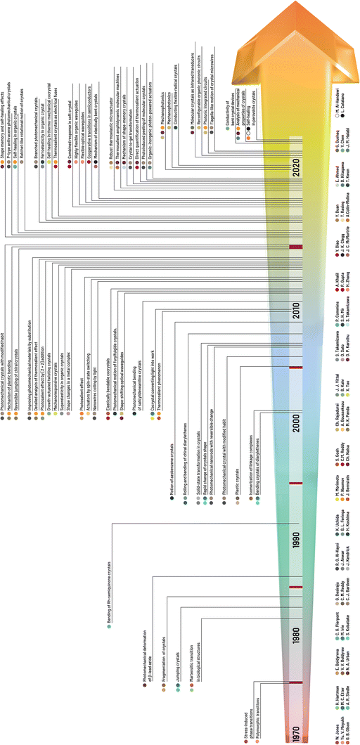 | ||
| Fig. 1 Chronology of the milestones in research on mechanical properties and effects of molecular crystals with the names of the main contributors to the research field of crystal adaptronics. | ||
Here, we present the main types of mechanical effects emphasizing recent research at the time of writing related to martensitic transitions (i.e., thermoelasticity, superelasticity, and ferroelasticity),34 which have been documented for organic/organometallic molecular crystals (Fig. 2). In addition, we briefly touch on categories of complex motion that typically arise from a combination of two or more independent effects.30 We note that given a rapidly evolving field, the categories presented here, rather than being definitive, serve only as a general guideline and nomenclature, and are subject to change to accommodate new discoveries and modes in crystalline transformations.
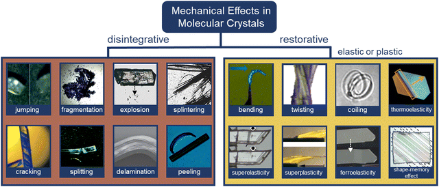 | ||
| Fig. 2 Categories of mechanical effects in molecular crystals. Disintegrative mechanical effects: jumping,37 fragmentation,40 explosion,41 splintering,42 cracking,43 splitting,44 delamination,45 and peeling.46 Restorative mechanical effects: bending,47 twisting,46 coiling,48 thermoelasticity,50 superelasticity,51 superplasticity,52 ferroelasticity,53 and shape memory effects.75 All images have been reproduced or adapted with permission from ref. 37 Copyright 2014, The Royal Society of Chemistry, ref. 40 Copyright 2016, American Chemical Society, ref. 41 Copyright 2018, Wiley-VCH, ref. 42 Copyright 1996, American Chemical Society, ref. 43 Copyright 2015, International Union of Crystallography, ref. 44 Copyright 2019, The Royal Society of Chemistry, ref. 45 Copyright 2015, Springer Nature, ref. 46 Copyright 2019, The Royal Society of Chemistry, ref. 47 Copyright 2013, American Chemical Society, ref. 48 Copyright 2017, The Royal Society of Chemistry, ref. 49 Copyright 2013, Wiley-VCH, ref. 50 Copyright 2018, Springer Nature, ref. 51 Copyright 2019, American Chemical Society, ref. 52 Copyright 2018, Springer Nature, ref. 75 Copyright 2019, Springer Nature, and ref. 54 Copyright 2019, American Chemical Society. | ||
1.2.2.1. Jumping. Jumping or hopping single crystals were first documented by Etter and Siedle (1983) in (phenylazophenyl)palladium hexafluoroacetylacetonate.55 Upon heating one facet of the crystal, the mechanical strain triggered the crystals to “fly off” the hot stage. The underlying molecular mechanisms indicate that on heating or cooling, rapid and anisotropic phase transitions allowed the crystals to jump upon stress release.56–59 Light and pressure have also triggered jumping in molecular crystals.60–62 Jumping results from several factors (e.g., amount of accumulated strain and the time scale of disintegration) caused by minuscule perturbations at a molecular level expressed by a sudden release of accumulated energy. In many cases, crystals may jump to dissipate energy through continued fragmentation concurrent with the jumping.60
1.2.2.2. Fragmentation. Photosalient derivatives of diarylethenes have shown rapid single crystal fragmentation upon irradiation with UV light.40 Fragmentation of single crystals was accompanied by a color change from colorless to blue. The photochromic fragmentations were rationalized by strain caused by disturbance of intermolecular hydrogen bonding in the single crystals upon ring opening of diarylethenes. Photosalient fragmentation has also been observed in [2+2]-photocycloaddition of discrete styrylpyridine Cu complexes forming 1D cyclobutane-based coordination polymers,63 and in [2+2]-photocycloaddition of diolefinic derivatives.64
1.2.2.3. Explosion. Strain/kinetic energy can be stored in crystals to harvest explosive mechanical responses. A representative case involves polymeric crystals derived from topochemical azide–alkyne reactions, in which humidity plays a critical role in modulating explosion (i.e., dehydration was used to trigger crystal explosion).41 Cocrystallization strategies have also been used to modulate the explosive response of materials (i.e., energetic cocrystals). For instance, common explosives 3,5,7-tetranitro-1,3,5,7-tetraazacyclooctane (HMX)65 and 2,4,6-trinitrotoluene (TNT) were cocrystallized with hexanitrohexaazaisowurtzitane (CL-20) to produce more powerful energetic materials that detonate upon mechanical stress.66 Modulation of explosive properties through cocrystallization relies on modifying packing coefficients, density, and thermal properties.66 Polymorphism also affects energy release from explosive crystals.67
1.2.2.4. Splintering. Splintering in single crystals has been typically observed as a needle-like fragmentation parallel to the long axis of the crystal. Splintering in single crystals is a common effect in enzymatic degradation of biomolecules and bacterial products, often causing the “splinters” to bend into curved loops.42,68 Studies revealed molecular self-assembly into a tubular packing to be of fundamental importance to the splintering of single crystals through degradation.69 Splintering in molecular crystals has also been documented during thermosalient transitions of N′-2-propylidene-4-hydroxybenzohydrazide56 and photosalient effects of 4-chlorocinnamic acid.70
1.2.2.5. Cracking. Cracks in single crystals have been observed as a result of strain release and often precede additional mechanical effects (e.g., jumping). They are commonly observed before actual disintegration occurs, but occasionally crystals crack without motion. A representative example involves a [2+2]-photodimerization reaction of 3,4-dimethoxycinnamic acid crystallized as blocks.43 Cracks perpendicular to the main elongation axis and double-bond plane quickly developed on exposure to UV light. It was rationalized that the built-up strain is released on cleaving the molecular planes, facilitated by the presence of slip planes in the crystal. Cracking was also observed when single crystals of disilanyl macrocycles were heated along crystallographic planes with relatively weak supramolecular contacts, followed by jumping.71
1.2.2.6. Splitting. Single crystals can often break into two or more parts. In the case of a triphenylethenyl gold isocyanide complex, splitting occurred perpendicular to the longest crystal axis with additional thermosalient responses (i.e., motion and bending).44 Here, a thermally induced phase transition caused expansion of the crystal length (i.e., major axis) and contraction of the thickness (i.e., shortest axis) resulting in an anisotropic strain release. Splitting has also been observed along the major axis of single crystals when they are subjected to localized heating. Twinned crystals of 1,2,4,5-tetrabromobenzene exhibited smooth splitting along their twinning interface when one of the components was heated.72
1.2.2.7. Delamination. Visible delamination of single crystals has been achieved through the application of mechanical stress (i.e., shearing) approximately parallel to the layers. The sliding of molecular layers resulted in a molecular rearrangement that accommodated the applied stress.13,73 For instance, partial delamination of single crystals facilitated plastic bending by enabling sliding of layers on top of each other.45,74,75 In another study, reversible photodelamination of crystalline microribbons of asymmetric perylene diimide was achieved by irradiation with a laser, which caused lateral sliding of stacked layers.76 Similarly, delamination of vinyl azides was caused by phototriggered gas release with UV light.77
1.2.2.8. Peeling. The capacity of crystals to undergo photoinduced peeling of surface layers has been observed in cis-olefins as a result of olefinic cis-to-trans and η1-SO2 to η1-OSO linkage photoisomerization effects.46,78 In the former case, UV light irradiation of cis-dimethyl-2(3-(anthracen-9-yl)allylidene)malonate (cis-DMAAM) block-like microcrystals resulted in delamination and curling in the longitudinal section of a single crystal. It should be noted that peeling occurred after the UV-light was turned off, suggesting it to be a result of molecular rearrangement. In the latter case, SO2 photoisomerization in a [Ru(NH3)4(SO2)(3-phenylpyridine)]Cl2·H2O complex caused the peeling effect to emanate from one end of the main crystal face, halting midway due to the presence of accumulated crystal strain from curling.
1.2.3.1. Bending. The bending of crystals, one of the most basic restorative mechanical effects of single crystals, has been widely documented since the early 19th century.38 Bending can arise predominantly during crystallization and phase transitions, photochemical transformations (e.g., cycloaddition and trans–cis isomerization), and from thermally or mechanically induced effects.29 Molecular underpinnings for crystals that bend elastically suggest an expansion of the crystal on the outer side and immediate restoration of the initial shape after the stimulus has been removed.75 Plastic bending (i.e., bending beyond the elastic limit) involves the slippage of molecular layers in the single crystals, causing the evolution of defects on partial delamination.13 In the case of N-(4-ethynylphenyl)-3-fluoro-4-(trifluoromethyl)benzamide, cooperative reconfigurations of CF3⋯CF3 interactions between adjacent molecular layers contribute to the mechanical bending of single crystals.74 In the context of photoinduced bending, permanent photomechanical trans–cis isomerization of cis-azobenzene compounds were performed by subjecting single crystal needles to UV irradiation.47 Upon irradiation, single crystals underwent irreversible bending to the opposite direction from the light source. Reversible photomechanical bending of trans-4-aminoazobenzene and oxazole crystals has also been observed,82,83 the latter resulting from a topochemical [2+2]-photodimerization. Cocrystals of desolvated perylene and 1,2,4,5-tetracyanobezene displayed a rare case of solvomechanical bending on exposure to tetrahydrofuran (THF) vapors.84
Our understanding of the reasons behind the elasticity, which is commonly observed with slender molecular crystals has particularly evolved over the past years. Even materials that have been traditionally considered very hard display elastic properties when they are small with high aspect ratios. Detailed X-ray diffraction studies of the copper(II) acetylacetonate complex85 have clearly shown that the bending of a crystal is accompanied by (or, occurs as a result of) rotation of the molecules, with a slight decrease in the distance between the neighboring molecules on the inner (concave) side and a slight increase in the distance on the outer (convex) side of the crystal. This work discredits an earlier hypothesis of molecular interlocking being the necessary condition for the elastic behavior. At the present state of knowledge, it appears that there is no single mechanism or structural feature that is a necessary condition for elasticity. Clearly, in the future, systematic and accurate studies will be needed to discern such features or a specific combination thereof, if they exist.
1.2.3.2. Twisting. Helical or twisted crystals may be considered bent in more than one direction. Although naturally occurring twisted crystals have been known for some time,86 the molecular mechanistic details have remained elusive. It has been established that a common requirement is the existence of at least two bending faces in a crystal.87 This observation has facilitated the bottom-up design of twisted helical crystals through mechanical deformation.48 Twisting has been achieved as a result of photochemical reactions in micro- and nano-sized crystals due to their increased ability to withstand exposure to UV radiation without polycrystalline fragmentation vs. macro-sized crystals (the higher surface-to-volume ratio dissipating the interfacial stress between unreacted/reacted phases/domains at surfaces).64,70,88 For instance, crystalline microribbons based on anthracene derivatives underwent twisting on exposure to UV light as a result of [4+4] photodimerization.70,89 Thermosalient twisting as a result of topochemical polymerization of azide and alkyne monomers,90 and molecular rearrangement of cocrystals has also been observed.91
1.2.3.3. Coiling. Crystals that wind or curl into coils or spirals due to twisting and bending have also gained attention due to their potential to be used as actuators. Molecular crystals containing boronate esters92 and 1,4-bis[2-(4-methylthienyl)]-2,3,5,6-tetrafluorobenzene93 coil around objects through mechanical manipulation. This effect is facilitated by a combination of bending (i.e., plastic deformation) and twisting (i.e., elastic deformation).29 Photoinduced coiling has been observed in straight nanowires of an anthracene derivative, dimethyl-2-(3-(anthracen-9-yl)allylidene)malonate,46 as a result of E-to-Z isomerization, where exposure to pulses of visible light triggered the nanowires to curl into bundles. The effect persists even after the light stimulus has been removed, while microwires made from 3-(anthracen-9-yl)acrylic acid94 curl into a closed loop upon continuous exposure to visible light.
1.2.3.4. Thermoelasticity. Thermoelasticity in single crystals originates in martensitic or other transitions occurring between high-temperature (HT) and low-temperature (LT) polymorphs that are which are related enantiotropically. Macroscopically, thermoelasticity in single crystals is accompanied by anisotropic changes in crystal shape and size that are reversible (i.e., elastic) due to cooperative molecular motion, thus facilitating shape recovery. Compared to elasticity alone, where recovery of the crystal shape is enabled by the capacity of molecules to resist deformation, thermoelasticity is enabled by cooperative polymorph transitions driven by thermal energy. Examples of molecular mechanisms in thermoelastic crystals include cooperative interlayer gliding of planes,95 conformational changes enabled by flexible molecules/motifs,50 and molecular rotation.96,97 It should be noted that thermoelasticity is a prerequisite for superelasticity and shape memory effects.98
1.2.3.5. Superelasticity. Superelasticity in single crystals is observed when a thermoelastic transition is triggered by a mechanical stimulus. It can be considered the mechanical analog of thermoelasticity. The mechanism of action involves the mechanical deformation of a single crystal through shear loading under isothermal conditions accomplished by altering the Gibbs free energy change of HT-to-LT phase transitions. In other words, the mechanical stress applied to thermoelastic crystals alters the thermodynamic equilibrium and facilitates cooperative elasticity through structural transitions, which is fundamentally different from intrinsic elasticity (i.e., resistance to change). After shear unloading, crystals exhibit shape recovery. An important characteristic of superelastic crystals is frictional work, which acts as a kinetic barrier resulting from structural defects.34 Superelasticity, albeit rare, has been found in molecular solids such as 6,13-bis(triiso-propylsilylethynyl)pentacene97 and terephthalamide99 crystals. Alternative molecular mechanisms for superelasticity exist that deviate from the conventional thermoelastic transitions. These include twinning transitions51,100 and transitions between monotropic phases.101
1.2.3.6. “Superplasticity”. “Superplastic” deformability in organic crystals has been reported for single crystals of N,N-dimethyl-4-nitroaniline.52 In this example, “superplasticity” is based on a multi-layer slipping mechanism that enables deformation of over 500% when shearing is along the tilt direction of the major axis. The difference between the “superplasticity” and regular plasticity, however, remains elusive because it is not clear to what extent a crystal needs to be plastic in order to be “superplastic”. The rationale for the “superplasticity” suggested that the highly anisotropic multilayer slipping is regulated by interlayer hydrogen bonding.52
1.2.3.7. Ferroelasticity. In a ferroelastic molecular crystal, a twinned deformed state is maintained when mechanical stress is applied, resulting in domains of two or more orientations. In addition, the domains are mechanically interconvertible when a reverse mechanical stress is applied. In a ferroelastic single crystal, the twinning domains are equally stable and do not recover spontaneously (i.e., detwinning) as in the case of superelasticity.34 Therefore, deformational twinning acts as the main molecular basis for ferroelastic transformations.53,97,102
1.2.3.8. Shape-memory effects. The discovery of the shape memory effect in molecular crystals is a milestone for the development of molecular crystals due to its resemblance to that of some metal alloys and polymers exhibiting multiple (thermo)mechanical transitions.30,33 It was first reported for a crystal of terephthalic acid, and later on, the details of the mechanism were explained.62,75 To engineer molecular crystals with shape memory, the common starting point is the ferroelastic twinning of a molecular crystal upon shear loading. Thermal treatment of the twinned structure restores the original shape by cooperative rearrangement during thermoelastic transitions. Cooling can either restore the original shape54,103 or induce twinning.75 Shape-memory has typically been discovered by serendipity. Further studies are needed to understand the full spectrum and applications of this mechanical effect.
2. Spontaneous growth-induced deformations
2.1. Ubiquity
A force applied to a crystal with forceps, or a light-field that can induce chemical changes, may cause bending and/or twisting, as amply illustrated herein. However, many crystals can deform themselves in the absence of apparent external forces. A large proportion (up to one-third) of molecular crystals can be made to twist as they grow.38,110–113 In some families of crystals, such as binary charge transfer complexes, the proportion can be greater than one-half.114 This group includes many common materials that have been studied for decades or more.115–119 Below we focus on twisting, the most spectacular and easily detected deformation, however spontaneous growth-induced deformations also include varieties of bending and scrolling.38 However, the great number of materials in this class raises a question: what kind of molecular objects deserve to be called crystals? Semi-infinite translational symmetry associated with a set of basis vectors remains a part of many serviceable definitions of a crystal, and helicoidal crystals choose to give this up.52.2. Evidence
Helicoidal crystals have two constants of the second-rank curvature tensor κ1 = −κ2, at an angle of ±π/4 between the orthogonal, tangential tensor components. Twisting is characterized by a pitch (length) associated with a 180° rotation of a crystal, P = π/φ, inversely proportional to φ, the twist per unit length. When twisted crystals are grown as discrete objects, from solution,120 vapor,121 and even from melts in some cases,119 their dimensions can be effectively determined by scanning electron microscopy (Fig. 3A and B). In many other instances, fine fibrils are packed in spherulites.122 In such cases, optical microscopy123 is the most incisive method of analysis (Fig. 3C–E). Polarization modulation techniques124 can be used to investigate the details of mesoscale stereochemistry and the organization of polycrystalline structures. (Fig. 3F and G).125–131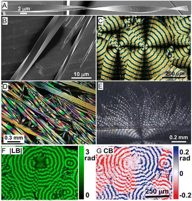 | ||
| Fig. 3 (A) SEM of twisted N-(2-thienylcarbonyl)glycine crystals grown from vapor.121 Adapted with permission from ref. 121 Copyright 2015, The Royal Society of Chemistry. (B) Cryo-SEM of several twisted benzamide (form II) needles with different cross-section sizes and pitches grown from aqueous solution.120 Adapted with permission from ref. 120 Copyright 2020, Wiley-VCH. (C) Polarized light optical micrograph of aspirin spherulite grown in the presence of salicylic acid. Concentric banding is a tell-tale feature of in-concert twisting of radial crystallites. (D) Assortment of hippuric acid needles grown from the melt between crossed polarizers. Most needles are twisted as indicated by the modulation of the interference colors. However, some large crystals show much more homogeneous retardance, indicating that the process of untwisting is mostly completed in these crystals. Adapted with permission from ref. 134 Copyright 2010, American Chemical Society. (E) Polarized light optical micrograph of a compact banded δ-mannitol spherulite growing from the melt in the presence of poly(vinylpyrrolidone) (lower part of the image). The compact spherulite opens into isolated twisted fibers when the material penetrates a vapor bubble (upper part of the image).132 Adapted with permission from ref. 132 Copyright 2012, American Chemical Society. (F) and (G) Micrographs of the absolute value of linear retardance (|LB|) and circular retardance (CB), respectively, of aspirin spherulites grown in the presence of salicylic acid and obtained using Mueller matrix polarimetry. Different signs of CB correspond to different senses of twisting in antipodal parts of the same spherulite. Panels (C), (F) and (G) have been adapted with permission from ref. 119 Copyright 2013, American Chemical Society. | ||
2.3. Symmetry
Helicoids are chiral; however, crystals of almost any symmetry can twist as they grow.133,134 No direct relationship between molecular or crystallographic chirality and sense of twisting is expected, which can be a counterintuitive fact to many chemists for whom chirality begets chirality. Nevertheless, enantiomorphous helices are correlated with stereogenic building components or the stereochemistry of twist-inducing additives (albeit growth conditions can affect the sense of twist in some materials).135 Heterochiral helices should be likewise correlated with enantiomorphous space groups and/or enantiopolar growth directions.136 Sometimes banded spherulites grow along polar directions, and then it becomes important to distinguish non-equivalent positive/negative growth directions. This can be achieved by monitoring growth with tailor-made additives.137,1382.4. Mechanisms
Even though the problems associated with crystal twisting have been brought forward in successive generations for more than a century, there is no consensus as to why so many crystals twist themselves as they grow. Given the diversity of simple structures that will form twisted crystals, it is likely that there is more than one reason for morphologies that deviate from lattices with long-range translational symmetry.38,132,139 The most important of them are briefly outlined below (Fig. 4).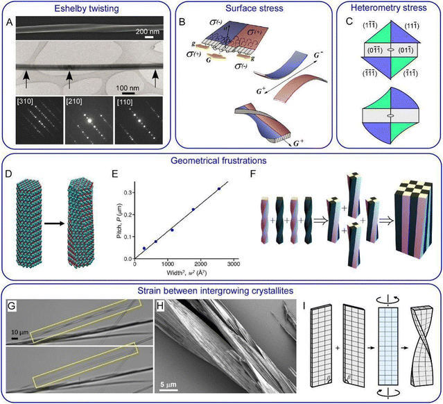 | ||
Fig. 4 Twisting mechanisms. (A) Eshelby twisting in GeS nanowires. Upper part: SEM image of a twisted nanowire. Middle part: TEM image of a nanowire with Eshelby twist. The dark line in the middle of the wire is in contrast to an axial screw dislocation. Lower part: convergent beam electron diffraction patterns taken from the locations marked by black arrows. They demonstrate the change of the crystal orientation along the wire from [110] to [210] and then to [310] with respect to the incident electron beam. Adapted with permission from ref. 158 Copyright 2019, Springer Nature. (B) Surface stress in thin crystals illustrated for polymer lamellae. Due to the difference in the polymer chain folding with respect to the growth front orientation (G and g indicate growth in the direction of lamella elongation and in the perpendicular direction, respectively) different parts of the lamella develop different signs of surface stress, σ, depicted in red and blue. If these two parts are separated, they would bend in opposite directions. But when bound together they decrease their elastic energy by twisting. Adapted with permission from ref. 152 Copyright 2016, Springer International Publishing. (C) Schematic diagram of heterometry stress in resorcinol crystals grown in the presence of tartaric acid. Enantiomorphous {11![[1 with combining macron]](https://www.rsc.org/images/entities/char_0031_0304.gif) } blue and {1 } blue and {1![[1 with combining macron]](https://www.rsc.org/images/entities/char_0031_0304.gif) ![[1 with combining macron]](https://www.rsc.org/images/entities/char_0031_0304.gif) } green faces adsorb and overgrow tartaric acid differentially. This can result in a change in lattice constants in corresponding growth sectors followed by the formation of sector specific strain and stress. Stress relaxation produces a twist moment at the crystal tip and twists the crystal. Adapted with permission from ref. 133 Copyright 2011, American Chemical Society. (D) Trigonal benzil nanocrystalline rod before (left) and after geometry optimization (right). Twisting is due to the intrinsic tendency of a comparatively small number of molecules decoupling themselves from a lattice characteristic of a large periodic crystal. (E) Pitch of an optimized benzil nanorod as a function of its cross-sectional area. Panels (D) and (E) are adapted with permission from ref. 154 Copyright 2020, American Chemical Society. (F) Untwisting during assembly of smaller components with a geometrical frustration. At each step, four identical twisted silicone rods are glued together in full contact, and the resulting structure is relaxed to its elastic energy minimum. Adapted with permission from ref. 156 Copyright 2019, The Royal Society of Chemistry. In both cases, panel (E) and (F), the pitch is proportional to the area of the rod cross-section as predicted by the theory.156 (G) Dissolution of one of two layers served to transform a twisted pair of benzamide (form II) crystals (upper image) into a single straight crystal (lower image). (H) Partial sublimation of benzamide in vacuum reveals a complex intergrowth of fine lamellae. (I) Schematic diagrams illustrating creation of misfit stress, twist moment, and twisting at the interface of (010) benzamide contact twin. Panels (G–I) are adapted with permission from ref. 120 Copyrights 2020, Wiley-VCH. } green faces adsorb and overgrow tartaric acid differentially. This can result in a change in lattice constants in corresponding growth sectors followed by the formation of sector specific strain and stress. Stress relaxation produces a twist moment at the crystal tip and twists the crystal. Adapted with permission from ref. 133 Copyright 2011, American Chemical Society. (D) Trigonal benzil nanocrystalline rod before (left) and after geometry optimization (right). Twisting is due to the intrinsic tendency of a comparatively small number of molecules decoupling themselves from a lattice characteristic of a large periodic crystal. (E) Pitch of an optimized benzil nanorod as a function of its cross-sectional area. Panels (D) and (E) are adapted with permission from ref. 154 Copyright 2020, American Chemical Society. (F) Untwisting during assembly of smaller components with a geometrical frustration. At each step, four identical twisted silicone rods are glued together in full contact, and the resulting structure is relaxed to its elastic energy minimum. Adapted with permission from ref. 156 Copyright 2019, The Royal Society of Chemistry. In both cases, panel (E) and (F), the pitch is proportional to the area of the rod cross-section as predicted by the theory.156 (G) Dissolution of one of two layers served to transform a twisted pair of benzamide (form II) crystals (upper image) into a single straight crystal (lower image). (H) Partial sublimation of benzamide in vacuum reveals a complex intergrowth of fine lamellae. (I) Schematic diagrams illustrating creation of misfit stress, twist moment, and twisting at the interface of (010) benzamide contact twin. Panels (G–I) are adapted with permission from ref. 120 Copyrights 2020, Wiley-VCH. | ||
2.5. Mechanics
Twisted crystals are known for all types of materials with a wide range of cross-sections with diameters from nanometers to a few centimeters. A majority of them, however, are molecular crystals growing at high homologous temperatures, T/Tm = 0.6–0.98, with small cross-section sizes, h = 50 nm–5 μm. Keeping in mind that the elastic modulus of molecular crystals was shown to decrease linearly as T/Tm increases,159 the force required to twist such a crystal will be small, thereby providing a rationale for the ubiquity of the phenomenon.The dependence of pitch, P, on cross-section size, h, typically obeys a power law P ∝ hn with the exponent n close to 1 (Fig. 5).38,121,132 This suggests that the twist is determined from the rigidity of a cross-section and the crystal untwists as it thickens. Indeed, the process of untwisting was experimentally observed for hippuric acid134 and mannitol.132 The closeness of the exponent to unity means that stress can remain elastic only if the twist is induced by stress between comparably sized domains located parallel to the crystal elongation direction (mechanisms in Sections 2.4.4 and 2.4.6). In all other cases, partial or full relaxation of elastic stress is expected. It is commonly observed that twisted morphologies are preserved upon crystal fragmentation, supporting the plastic nature of the deformation.
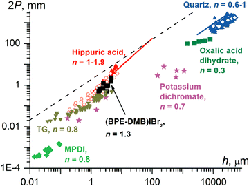 | ||
| Fig. 5 Correlation between the full twisting period (2P, 2π rotation, mm) and the smallest crystal size in a cross-section (h, μm). Blue symbols: quartz (up triangles, open diamonds, and the line corresponds to different sources of data); olive squares: oxalic acid dihydrate; magenta stars: potassium dichromate; black squares: (1,4-bis[2-(pyrene-1-yl) vinyl]-2,5-dimethylbenzene)IBr2, (BPE-DMB)Ibr2; red symbols: hippuric acid (up triangles = melt grown crystals); open circles = vapor grown crystals; line = melt and solution grown crystals; dark yellow down triangles: N-(2-thienylcarbonyl)glycine, TG; green diamonds: poly(m-phenylene isophthalamide), MPDI. The values of n are exponents in the fit P = khn. In the region below the dashed line, 2P < 103πh, elastic stress in twisted crystals should relax, at least partially.121 Adapted with permission from ref. 121 Copyright 2015, The Royal Society of Chemistry. | ||
For most crystals, shear strain on the crystal surface is higher than γ = πh/(2P) > 0.001 (Fig. 5). On deformation mechanism maps,160 crystallization at homologous temperatures T/Tm = 0.6–0.98 corresponds to diffusional flow, dislocation creep, or conventional plastic flow. Nanoscale molecular crystals (h = 50 nm–5 μm) typically contain no or very few dislocations,121 meaning that plasticity cannot be dislocation mediated. However, it can be easily mediated by the flow of vacancies.
3. Photomechanical molecular crystals
3.1. Advantages of using photomechanical molecular crystals
 | (4) |
3.2. Types of photochemical reactions in photomechanical crystals
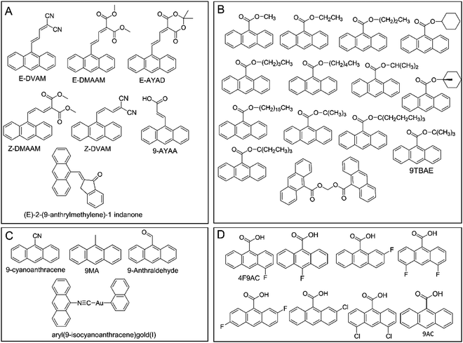
Photomechanical crystals that rely on the trans–cis photoisomerization of olefins are less common due to the tight packing of the crystals, which restricts motion. However, there are a few exceptions. Needle-like crystals of naphthylvinylbenzoxazole186 show directional photoinduced bending upon exposure to UV light (Fig. 6A). Single crystals or nanowires of (E)-2-(3-(anthracen-9-yl)allylidene)malononitrile (E-9DVAM) show bending towards light when irradiated with visible radiation and can be reset by exposure to UV light (365 nm)187 (Fig. 6B). Ultra-long microwires of (Z)-2-(3-(anthracen-9-yl)allylidene)malononitrile (Z-9DVAM) can twist and propagate autonomously when exposed simultaneously to visible and UV light (Fig. 6C). Similar anthracene derivatives show unique photoisomerization-induced coiling and solvent incorporation that is facilitated by the presence of surfactants such as cetyltrimethylammonium bromide (CTAB) and sodium dodecyl sulfate (SDS).49,188,189
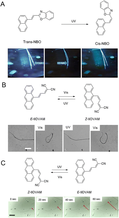 | ||
| Fig. 6 Optical micrographs of (A) trans-NBO needle-like microcrystals bending towards UV (365 nm).186 Adapted with permission from ref. 186 Copyright 2018, Wiley-VCH (B) E-9DVAM nanowires ca. 230 nm in diameter actuated during alternating exposure to UV and visible light. The scale bar is 10 μm.187 Adapted with permission from ref. 187 Copyright 2016, The Royal Society of Chemistry (C) Z-9DVAM microwire irradiated simultaneously with UV and visible light. The microwire propagates on the surface after 20, 40, and 80 s, as indicated by the red arrow. The scale bar is 230 μm.190 Adapted with permission from ref. 190 Copyright 2021, Wiley-VCH. | ||
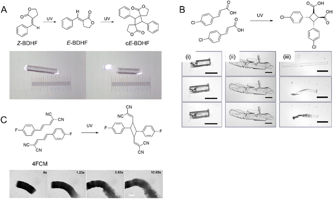 | ||
| Fig. 7 (A) Snapshots of photosalinet Z-BDHF crystals splitting into fragments after UV exposure and [2+2] photodimerization.194 Adapted with permission from ref. 194 Copyright 2015, American Chemical. Society (B) [2+2] photodimerization of 4Cl-CA. Optical images of three crystal shapes of 4Cl-CA (i) rectangular prism crystal, (ii) plate crystal, and (iii) microribbons. Top images were taken before UV (365 nm) exposure, the middle images were taken after 5 min exposure, and the bottom images were taken 1 h after exposure. Scale bars: 50 μm.70 Adapted with permission from ref. 70 Copyright 2012, The Royal Society of Chemistry. (C) Optical micrograph of a crystalline 4FCM nanowire bundle undergoing [2+2] photocycloaddition when exposed to 405 nm.199 The scale bar is 50 μm. Adapted with permission from ref. 199 Copyright 2020, The Royal Society of Chemistry. | ||
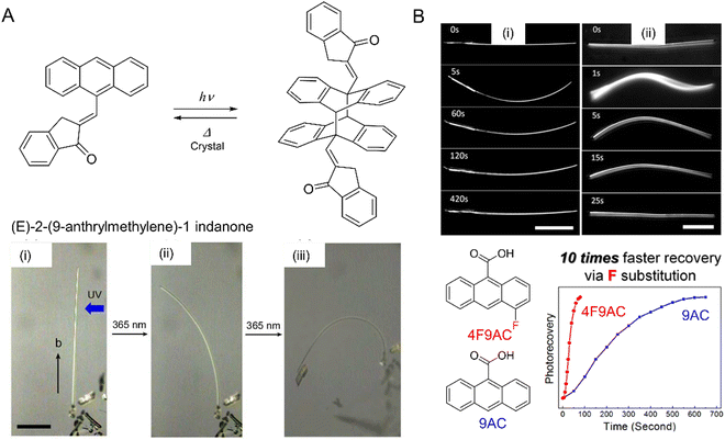 | ||
| Fig. 9 (A) Chemical structures and photochemical reaction. Pictures of narrow plate-like microcrystals of (E)-2-(9-anthrylmethylene)-1-indanone irradiated with UV (365 nm) leading to [4+4] photodimerization and bending of the crystal (i) before and after UV irradiation from the right for (ii) 4 and (iii) 13 min. The scale bar is 100 μm.212 Adapted with permission from ref. 212 Copyright 2016, The Royal Society of Chemistry. (B) Optical micrographs of (i) 9-anthracene carboxylic acid (9AC) and (ii) 4-fluoro-9-anthracene carboxylic acid (4F-9AC). The 4F-9AC crystal completely untwists in 25 s, while the 9AC crystal requires 420 s to unbend. Both scale bars are 50 μm. Plot: Photorecovery vs. time plot for 4F-9AC vs. 9AC.214 Adapted with permission from ref. 214 Copyright 2014, American Chemical Society. | ||
The [2+2] and [4+4] photodimerization reactions tend to have limited reversibility. Anthracene photodimers can, in principle, be reverted to monomer units by heating or irradiation at 254 nm. In practice, thermal “unzipping” at elevated temperature is detrimental to the crystal structure, and 254 nm irradiation cannot achieve 100% back reaction due to the formation of a photostationary state and secondary photoreactions. However, thermal reversibility can be achieved when substituted anthracenes crystallize in a head-to-head “syn” arrangement,213 rather than a head-to-tail “anti” arrangement common for most 9-substituted anthracenes. This reversible photochemistry offers the potential to use photomechanical crystals of 9-anthracene carboxylic acid (9AC) and its derivatives as thermally reversible (T-type) photoactuators213–215 (Fig. 9B).
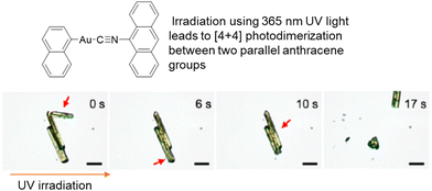 | ||
| Fig. 10 Optical micrographs of microcrystals of an aryl(9-isocyanoanthracene)gold(I) complex exhibiting photosalient effects when irradiated with UV light (365 nm). The thick red arrows indicate the position of the crystals that jumped. Scale bars represent 50 μm.218 Adapted with permission from ref. 218 Copyright 2021, American Chemical Society. | ||
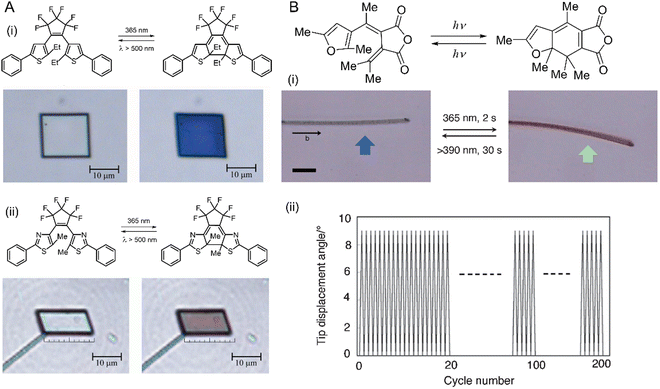 | ||
| Fig. 11 Photomechanical effects of diarylethene crystals. (A) Chemical structures and optical microscopic images of the photomechanical deformation of two diarylethene compounds (i) and (ii) upon irradiation with ultraviolet (365 nm, left) and visible (500 nm, right) light leading to a reversible contraction by 7%. Crystal thickness ≈ 330 nm.220 Adapted with permission from ref. 220 Copyright 2007, Springer Nature. (B) Chemical structures and photoreaction of a furylfulgide derivative. (i) Images of the reversible bending (blue arrow, 365 nm; green arrow, >395 nm) of a narrow, plate-like crystal of furylfulgide by as many as 200 cycles (ii). Scale bars are 20 μm.223 Adapted with permission from ref. 223 Copyright 2012, The Chemical Society of Japan. | ||
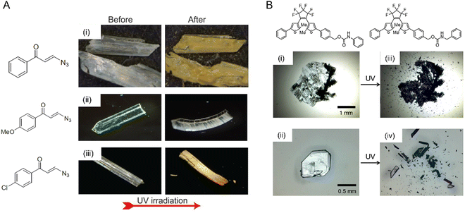 | ||
| Fig. 12 Mechanical effects due to the evolution of the photosalient effect. (A) Optical micrographs of microcrystals made from (i) 3-azido-1-phenylpropenone with a crystal size of ∼1.6 × 0.5 × 0.1 mm, (ii) 3-azido-1-(4-methoxyphenyl)propanone with a crystal size of ∼1.5 × 0.3 × 0.1 mm, and (iii) 3-azido-1-(4-chlorophenyl)propanone with a crystal size of ∼2 × 0.5 × 0.2 mm undergoing a photomechanical effect with the release of dinitrogen gas upon UV irradiation.77 Adapted with permission from ref. 77 Copyright 2020, American Chemical Society. (B) Optical micrographs of two diarylethene derivatives undergoing a violent photosalient effect upon UV light exposure. (i) and (ii) Before UV exposure and (iii) and (iv) after UV exposure.40 Adapted with permission from ref. 40 Copyright 2016, American Chemical Society. | ||
3.3. Examples of crystals as energy transducers
Long crystals of diarylethene derivatives have been shown to bend reversibly in response to a specific wavelength of light. In some cases, the bending speed was fast enough to impart a momentum and, in some cases, to lift heavy objects.245 Azobenzene derivatives were extensively studied since they exhibit thermally reversible bending (T-type) with reset times that can be tuned by modifying the chemical structure of the azobenzene derivative. A study of the photomechanical response of halogenated cinnamic acid derivatives, such as 4-chlorocinnamic acid, showed that the thickness of the crystal plays a significant role in determining the photomechanical motion.70 The degree of bending can be very small; nanowires made from diarylethene246 (Fig. 13A) or 9AC247 (Fig. 13B) can bend reversibly following a P- and T-type mechanism, respectively. Highly branched microcrystals of 4-fluoro-9-anthracene carboxylic acid (4F-9AC) can have multiple arms that bend in unison248 (Fig. 13C) upon exposure to UV light.
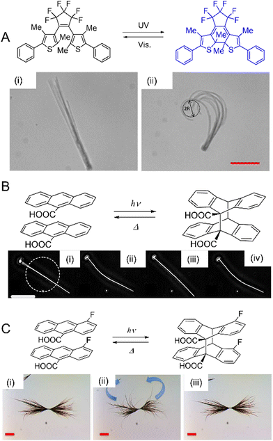 | ||
| Fig. 13 Examples of crystal bending. (A) Diarylethene derivative nanowires before (i) and after (ii) 365 nm UV light irradiation. R = bend radius. Scale bar = 20 μm.246 Adapted with permission from ref. 246 Copyright 2018, The Royal Society of Chemistry. (B) Dark field optical micrographs of the nanowire, made from 9AC, with a diameter of ca. 230 nm, (i) before UV exposure, (ii) bending after brief exposure to 365, (iii) reversible or resetting after 10 minutes at room temperature, and (iv) bending after brief exposure to 365 nm. Scale bar = 20 μm.247 Adapted with permission from ref. 247 Copyright 2007, Wiley-VCH. (C) Optical micrographs of highly branched microcrystals of 4F-9AC. (i) Before exposure to UV (365 nm), (ii) during UV exposure with curling branches, and (iii) 10 s after thermal relaxation at room temperature, the arms reset. Scale bar = 25 μm.248 Adapted with permission from ref. 248 Copyright 2017, The Royal Society of Chemistry. | ||
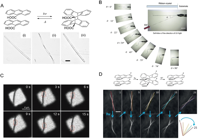 | ||
| Fig. 14 Examples of crystal twisting. (A) Reversible twisting of 9AC microribbon: (i) before irradiation; (ii) immediately after irradiation with 365 nm light; and (iii) untwisting after 9 min in the dark at room temperature. Scale bar = 20 μm.89 Adapted with permission from ref. 89 Copyright 2011, American Chemical Society. (B) Sequence of images of a flat microcrystal of 1,2-bis(2-methyl-5-phenyl-3-thienyl)perfluorocyclopentene exhibiting diverse twisting motions depending on the angle of the incident UV light. The scale bar is 300 μm.221 Adapted with permission from ref. 221 Copyright 2018, American Chemical Society. (C) Confocal scanning laser micrograph of twist propagation along a typical microribbon of perylenediimide derivatives bridged on a copper grid.250 Adapted with permission from ref. 250 Copyright 2019, Wiley-VCH. (D) Dark-field optical micrograph of an X-shaped microcrystal of 4F-9AC that rotates clockwise after brief irradiation with UV light with five cycles being shown.109 Scale bar: 20 μm. Adapted with permission from ref. 109 Copyright 2016, Wiley-VCH. | ||
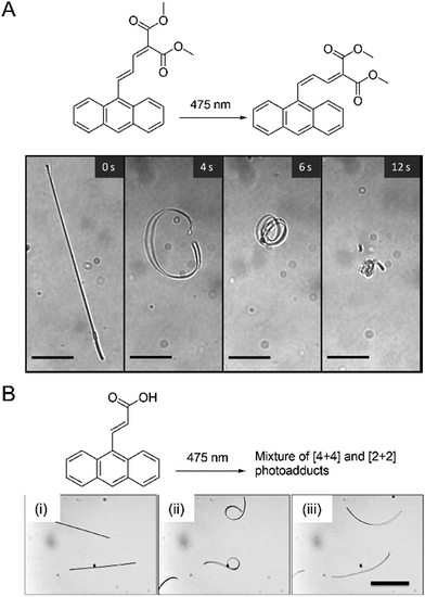 | ||
| Fig. 15 Examples of crystal coiling. (A) Molecular structure and photoisomerization of E-DMAAM. Crystalline nanowires made from E-DMAAM with ca. 230 nm diameter suspended in an aqueous surfactant coil after exposure to 1 s pulse of 475 nm light. Coiling continues even after the light is switched off. Scale bar, 10 μm.49 Adapted with permission from ref. 49 Copyright 2013, Wiley-VCH. (B) 9-AYAA microwires suspended in water coil and uncoil with continuous exposure to 475 nm light, (i) before exposure, (ii) halfway, (iii) total exposure. Scale bar, 30 μm.94 Adapted with permission from ref. 94 Copyright 2015, The Royal Society of Chemistry. | ||
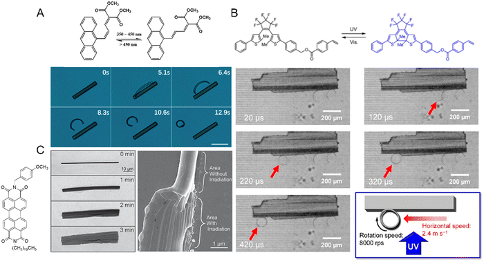 | ||
| Fig. 16 Crystal delamination and peeling. (A) Structure and optical micrograph of a cis-DMAAM microcrystal photoinduced peeling after exposure to a 1 s pulse from 405 nm light. Scale bar, 5 μm.46 Adapted with permission from ref. 46 Copyright 2019, The Royal Society of Chemistry. (B) Photoinduced fast peeling and curling of a diarylethene derivative. The red arrow indicates the position and direction of the peel.251 Adapted with permission from ref. 251 Copyright 2021, American Chemical Society. (C) Optical micrograph (left) and scanning electron micrograph (right) of a microribbon made from the corresponding perylene diimide derivative laterally expanding upon exposure to 488 nm.76 Adapted with permission from ref. 76 Copyright 2015, Wiley-VCH. | ||
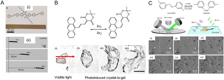 | ||
| Fig. 17 Photoinduced crawling of crystals. (A) Molecular structure of the perylene derivative (i), and optical micrographs (ii) of a microcrystal (length 20 μm and width 2 μm) traveling across a glass slide while being irradiated with a 405 nm laser.257 Adapted with permission from ref. 257 Copyright 2020, Wiley-VCH. (B) Optical micrographs of (E)-AYAD microcrystals suspended in an aqueous surfactant solution under visible light irradiation, (i) original crystal shape outlined by a red rectangle, (ii)–(iiii) expansion of the crystal forming a gel after several minutes of continuous light exposure. Scale bar, 50 μm.189 Adapted with permission from ref. 189 Copyright 2019, Wiley-VCH. (C) Chemical structure of the photoisomerization reaction 3,3′-dimethylazobenzene. A schematic diagram of the experimental setup. Optical micrographs of microcrystal motion after irradiation for t = 0 (i), 3 (ii), 6 (iii), 10 (iv), 15 (v) and 20 min (vi). Scale bar, 50 μm.108 Adapted with permission from ref. 108 Copyright 2015, Springer Nature. | ||
 | ||
| Fig. 18 Photoinduced crystal expansion. (A) Atomic micrographs of a 9-TBAE nanowire, ca. 230 nm diameter (i) before illumination and (ii) after illumination at 365 nm showing lateral expansion by 15%. Scale bar, 6 μm.204 Adapted with permission from ref. 204 Copyright 2006, American Chemical Society. (B) Optical micrographs of plate-like microcrystals of 9MA upon UV (405 nm) irradiation. The crystal expands along the long axis over a period of ca. 8 min (left to right panel).265 Adapted with permission from ref. 265 Copyright 2022, Wiley-VCH. | ||
3.4. Preparation of photomechanical crystals
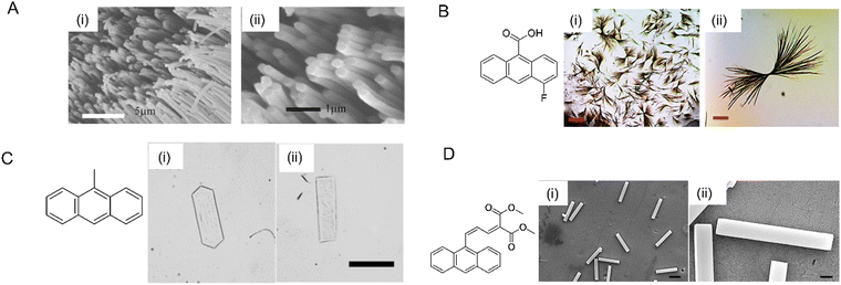 | ||
| Fig. 19 Photomechanical crystals prepared by using different methods. (A) Scanning electron microscopy image of molecular crystal nanowires of a perylene derivative (molecular structure on the left) grown via solvent annealing inside AAO templates, (i) zoomed-out image, and (ii) zoomed-in image revealing the solid cores of the nanowires.263 Adapted with permission from ref. 263 Copyright 2006, The Royal Society of Chemistry. (B) Optical micrographs of 4F-9AC highly branched microcrystals, (i) scale bar 400 μm and (ii) scale bar 50 μm.248 Adapted with permission from ref. 248 Copyright 2017, The Royal Society of Chemistry. (C) Optical microscopy image of two types of 9MA thin microplate crystals, (i) hexagonal and (ii) rectangular; scale bar 50 μm.208 Adapted with permission from ref. 208 Copyright 2018, Wiley-VCH. (D) Scanning electron micrographs of Z-DMAAM microblocks and (D) scanning electron micrographs of Z-DMAAM microblocks; (i) scale bar 100 μm, (ii) scale bar 10 μm.46 Adapted with permission from ref. 46 Copyright 2019, The Royal Society of Chemistry. | ||
Ionic, neutral, and copolymer surfactants can be used to control the shapes and sizes of organic crystals precipitated from aqueous solutions containing a surfactant above its critical micelle concentration. A variety of different crystal habits have been obtained, including fibers, cubes, octahedra, microblocks, wires, etc.46,208,285–287 A surfactant-mediated two-step reprecipitation method was used to grow single-crystal platelets composed of 9MA with two different molecular orientations208 (Fig. 19C). Similar approaches were used to grow microblocks of DMAAM crystals (Fig. 19D)46 and ultralong Z-9DVAM microwires.190 Although this method often requires considerable trial and error to find a suitable solvent/surfactant combination, it can afford to novel crystal shapes.
3.5. Current status and applications of photomechanical molecular crystals
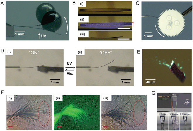 | ||
| Fig. 20 Simple demonstration of work performed by dynamic molecular crystals. (A) Superimposed photographs of a diarylethene cocrystal cantilever microcrystal lifting a 2 mm lead ball, 46.77 mg; before and after irradiation with UV (365 nm) light, as indicated by the white arrow.245 Adapted with permission from ref. 245 Copyright 2010, American Chemical Society. (B) Photographs of the 4FCM/AAO composite lifting a mirror (mass, 1.28 g) under UV light irradiation from below, (i) before light, (ii) After UV (365 nm) exposure, and (iii) template remains curved after the mirror is removed. Scale bars, 5 μm.199 Adapted with permission from ref. 199 Copyright 2020, The Royal Society of Chemistry. (C) Gearwheel rotation activated by rod-like cocrystals containing diarylethene. The microcrystal is actuated by alternate irradiation with visible and UV light.300 Adapted with permission from ref. 300 Copyright 2016, The Society of Synthetic Organic Chemistry. (D) Photomechanical crystal acts as an on/off current switch upon alternating irradiation with UV and visible light.298 Adapted with permission from ref. 298 Copyright 2015, The Royal Society of Chemistry. (E) Optical micrograph of 1,2-bis(5-phenyl-2-methyl-4-thiazolyl)perfluorocyclohexene hollow microcrystals containing fluorescent microbeads. These crystals explode upon UV exposure, leading to scattering of fluorescent beads. Scale bars, 20 μm.222 Adapted with permission from ref. 222 Copyright 2017, Wiley-VCH. (F) Optical micrographs of highly branched microcrystals of 4F-9AC sweeping silica microspheres in suspension (i) before UV light exposure, (ii) during UV (365 nm) light exposure, and (iii) after several exposure cycles. Scale bars, 25 μm.248 Adapted with permission from ref. 248 Copyright 2017, The Royal Society of Chemistry. (G) Optical microscopy images of Azo-1 and PS nanowire (500 nm (d) × 12.5 mm (l)) arms integrated on the tip of a glass microcapillary tube. The photoinduced tweezers grip a PS microparticle (d ≈ 4 μm) on a silicon substrate upon irradiation with UV light: 1 (contact) → 2 (gripping) → 3 (detachment). Scale bar, 20 μm.299 Adapted with permission from ref. 299 Copyright 2015, The Royal Society of Chemistry. | ||
Another example of particle manipulation was accomplished by highly branched sheaf-like microcrystals of 4F-9AC.248 The branched microcrystals were obtained by slow acid hydrolysis of a tert-butyl ester of 4F-9AC in aqueous phosphoric acid/SDS/1-dodecanol at 35 °C. Upon exposure to 405 nm light the microcrystal branches twisted in unison, sweeping away more than 75% of silica microspheres in their vicinity. This photomechanical actuation can be repeated indefinitely after the branches return to their original shape within seconds (Fig. 20F). More precise manipulation of single microspheres was demonstrated by Je and Kim's group, who prepared organic crystal nanowires composed of an azobenzene-containing chromophore, tris(4-((E)-phenyldiazenyl)phenyl)benzene-1,3,5-tricarboxamide (Azo-1), using a meniscus-guided solidification method.299 The nanowires showed photomechanical bending and unbending with large displacement upon irradiation with UV and visible light, respectively. Photomechanical nanowire tweezers were created with an Azo-1 nanowire arm that moved against a fixed polystyrene (PS) nanowire arm (Fig. 20G). The photomechanical tweezers can pick up, move and release the sphere, providing a way to manipulate micro-objects without wires or electrodes.
4. Computational methods for studying and predicting mechanical properties and effects in molecular crystals
4.1. From rationalizing to predicting mechanical effects
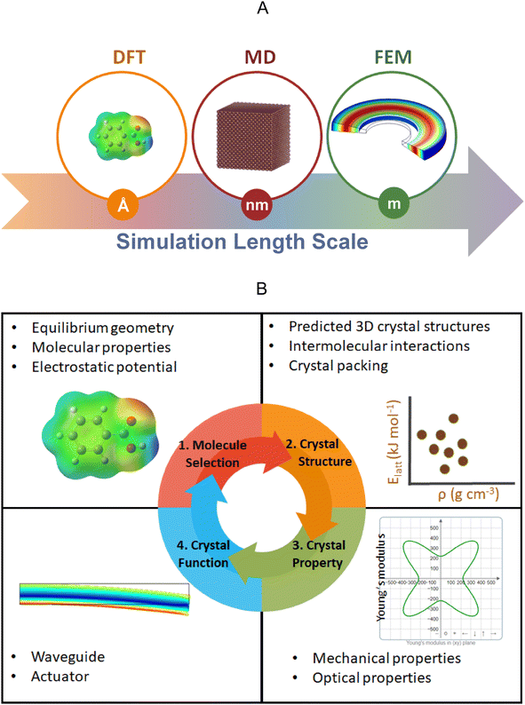
Computational methods are indispensable in understanding the chemical reactivity301,302 and physical properties303,304 of a wide range of materials. With the widespread availability of high-performance computing facilities and the increasing adoption of unsupervised machine learning techniques,305,306 the volume of information that can now be processed using computer algorithms is significantly larger than was the case 20 years ago. This trend is set to continue in the coming decades, creating new opportunities for the application of computational methods to support the discovery of mechanically responsive molecular crystals.However, despite this promise, most of the reported discoveries concerning mechanically responsive molecular crystals are currently made with minimal, if any, computational insight. Rather than applying computational methods a priori to support the discovery of new mechanically responsive molecular crystals, it is more common to see reports where investigators have applied computational methods after the experimental observation of some mechanical effect, in order to gain a deeper understanding of the mechanistic origins of these phenomena (for example, see ref. 215). This suggests that the promise of true in silico design and subsequent experimental discovery of mechanically responsive molecular crystals is yet to be realized. Computational methods that span a range of lengths and timescales (Fig. 21) are already used to understand the mechanical properties of crystalline inorganic307 and ceramic materials.308 The commonly used modeling techniques to estimate the mechanical properties in such systems include density functional theory, molecular dynamics, and finite element methods. Although most of the reported studies that use these techniques to understand mechanical effects relate to studies on inorganic and ceramic materials; there is a growing disparity between the increasing amount of mechanical data and effects that experimentalists are reporting on molecular crystals and the scarcity of computational data that can be used to corroborate the emerging theories and hypotheses on the mechanical effects in molecular crystalline materials. This reflects the fact that there are more experimentalists than theoreticians who are currently interested in the mechanical properties and effects of molecular crystalline materials. Nevertheless, we anticipate that with the increasing interest in the mechanical properties and effects of molecular crystals, computational methods will play a significant role in correlating not only the structure to the properties but also properties to function in the future.
The increasing body of literature on mechanically responsive molecular crystals has already produced some guiding principles as to what types of molecules may display a particular type of mechanical effect. For example, the photomechanical bending seen in several azobenzene crystals47,179,309 requires the presence of an azo group that can undergo trans–cis isomerization upon irradiation with light. While most organic crystals display relatively low Young's moduli (5–45 GPa),27 the exceptional mechanical stiffness of amino acid310 crystals is correlated with the strong charge-assisted hydrogen bonding interactions. This suggests that careful manipulation of the types and strengths of intermolecular interactions observed in molecular crystals may support the optimization of the bulk mechanical properties. Indeed, there have been some successes in the application of the principles of crystal engineering311 to support the discovery of novel mechanically responsive crystalline materials.32 For example, the introduction of slip planes in molecular crystals via the careful manipulation of the functional groups in molecules is a viable crystal engineering strategy for the discovery of plastically bendable molecular crystals.4 Recent work using a combination of nanoindentation and microfocused synchrotron X-ray radiation has validated the accuracy of this slip-plane model in explaining the mechanistic origins of plastic bending in molecular crystals.74 Despite these successes, it is not yet clear whether we have enough reported examples of mechanically responsive molecular crystals to support the proposal of a set of generally applicable empirical rules for guiding the discovery of such materials.
At present, trial-and-error experiments remain the most common route for the discovery of new mechanically responsive molecular crystals. The process typically starts with the choice of suitable candidate molecules, which is often made by comparing the crystal structures adopted by these molecules with those of related molecules that may either have similar functional groups and/or similar crystal packing. This is followed by the growth of suitable single crystals. Finally, the mechanical properties (e.g., Young's moduli and hardness) are measured on experimentally accessible crystal faces by nanoindentation. Each of these steps either requires a set of underlying assumptions or carries some technical challenges (e.g., crystal growth) that vary for each chemical under investigation. In this section, we discuss: what role can computational methods play in not only rationalizing the experimentally observed mechanical effects but also supporting the discovery of new materials with desirable mechanical effects? We start with a critical assessment of the current applications of computational methods in the field before providing an outlook for the role that computational methods may play in the future.
4.2. Computing the strength of intermolecular interactions and crystal morphologies
Upon the application of a stimulus (stress, light, etc.), the mechanical response of a crystal is influenced by the habit (or morphology) and bulk crystal density of the material. At a molecular level, the strength of the intermolecular forces between the molecules is critical in influencing both properties. Most molecular crystals display anisotropic intermolecular interactions due to the uneven charge distribution around the constituent molecules. As such, the observed intermolecular forces are likely to be strong along certain crystallographic axes while they may be weak in others.The importance of quantifying both the strength and directionality of the intermolecular forces in the study of mechanically responsive materials, has led to the widespread adoption of energy framework (EF) calculations.312,313 EF calculations provide a quantitative method for correlating the strength of intermolecular interactions to the observed mechanical properties (e.g., hardness or stiffness) along specific crystallographic directions or faces.77,314,315 This permits the quantitative comparison of the strength of the intermolecular interactions (Fig. 22) as a function of the observed mechanical properties (e.g., brittle, plastic and elastic) of the crystals.314 EF calculations start by computing the unperturbed molecular wavefunctions at a chosen level of theory, followed by an estimate of the total interaction energy (Etot) in the crystal as the sum of the electrostatic (Eele), polarization (Epol), dispersion (Edis) and exchange-repulsion (Erep) terms according to the following equation:
| Etot = Eele + Epol + Edis + Erep | (5) |
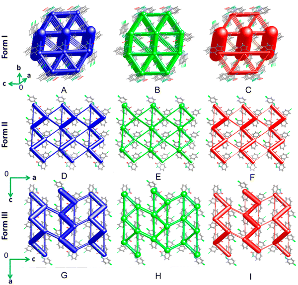 | ||
| Fig. 22 Energy frameworks (EFs) showing the (A, D and G) total interaction energies (blue), dispersion (B, E and H) contributions (green) and electrostatic (C, F and I) contributions (red) for forms I (brittle), II (plastic) and III (elastic), respectively, for the Schiff base 3-((4-chlorophenyl)imino)indolin-2-one. Adapted with permission from ref. 314 Copyright 2018, American Chemical Society. | ||
Another important application of the theory of intermolecular forces that can be used to support the discovery of mechanically responsive molecular crystals, is the prediction of crystal morphologies using computational methods.320,321 Although such calculations are not as widely used as EFs among the growing community of researchers interested in the mechanical effects of molecular crystals; they are integral to the advancement of in silico methods for supporting the discovery of mechanically responsive molecular crystals (Fig. 21). Experimentalists working in the field currently perform the face-indexing of crystals using laboratory X-ray diffraction methods before performing nanoindentation experiments. However, if we are to advance the in silico discovery of mechanically responsive molecular crystals (Fig. 21), then accurate computational models for predicting crystal morphologies will be necessary since the crystal habit affects its response to mechanical stress.
The simplest computational model for predicting crystal morphologies uses the Bravais–Friedel–Donnay–Harker (BFDH) law.322 BFDH morphologies are purely geometrical in nature and assume that the growth rate of a given face is inversely proportional to the interplanar distance between the layers parallel to that face. The BFDH morphologies work relatively well for crystals displaying quasi-isotropic intermolecular interactions but are not reliable for predicting morphologies in crystals displaying highly anisotropic intermolecular interactions. In such cases, the attachment energy model323,324 can be used to estimate the relative growth rates of the crystal faces.
Both EF and morphology calculations rely on an input 3D crystal structure, which is almost always determined using laboratory X-ray diffraction methods. However, for the first-principles discovery of mechanically responsive molecular crystals, one would start with the 2D chemical structure of a candidate molecule and the first step would be to compute the set of energetically accessible 3D crystal structures for the candidate molecule (Fig. 21). Recent advances in computational methods of crystal structure prediction (CSP) suggest that this is now feasible for relatively small molecules with limited degrees of freedom.325 The putative set of predicted crystal structures would then be ranked according to stability and the most stable predicted structures would be subjected to property predictions including but not limited to morphology calculations and the second-order elastic constants (Section 4.3 below). We can therefore envisage a future where several computationally predicted crystal structures will be subjected to theoretical stress–strain tests on specific crystallographic faces using the computed crystal morphologies as a guide for selecting the dominant face(s). This may be supplemented with EF calculations to quantify the strength of the intermolecular interactions along specific crystallographic directions or to identify slip planes in the predicted crystal structures. By comparing the predicted crystal structures and properties from a large pool of candidate molecules, the theoretical data may be used to select and advance the experimental crystallization and mechanical characterization of a limited set of candidate molecules. Such an approach has already been applied successfully for the discovery of porous molecular crystals using energy–structure–function maps (Fig. 23),326 which relate the predicted polymorphs on the crystal energy landscape to a set of user-specified molecular/crystal descriptors. For research focused on mechanically responsive molecular crystals, the descriptors chosen could be the computed Young's modulus, compressibility or the number of active slip planes present in the predicted crystal structures.
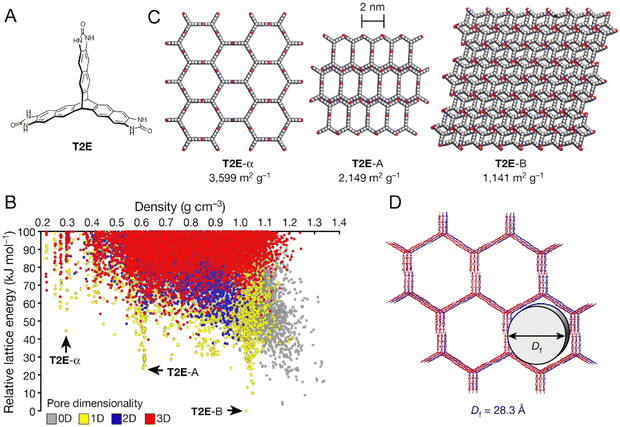 | ||
| Fig. 23 Comparison of the predicted and experimental structures and properties for molecule T2E whose molecular structure is shown in panel (A). The predicted crystal energy landscape for T2E is shown in panel (B). Selected structures for T2E from the energy-density landscape are shown in panel (C). An overlay of the predicted (red) and experimental (blue) structures for T2E is given in panel (D). Adapted with permission from ref. 326 Copyright 2017, Springer Nature. | ||
4.3. Computing the second-order elastic constants of molecular crystals
The accurate computation of the second-order elastic constants (SOECs) of molecular crystals provides the opportunity to estimate a range of mechanical properties such as Young's and bulk moduli. The tensorial representation of Hooke's law provides access to the SOECs of a crystal that is deformed within the elastic regime. The relevant equation is | (6) |
 | (7) |
 | (8) |
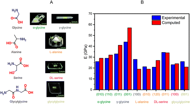 | ||
| Fig. 24 (A) Chemical structures and photographic images of a number of amino acid crystals. For each photographic image of the crystal, the Miller indices for specific crystallographic faces studied are indicated. (B) Bar graph for comparing the experimental (nanoindentation) and computed Young's moduli (E values) for the amino acids shown in panel (A). For each amino acid where the computed and experimental E values are compared in the bar graph, the same color is used on the x axis to match the name of the amino acid with the Miller index of the crystallographic face studied. The bar graph shown in panel (B) is based on the data reported in ref. 310. The images of the crystals and the data for the bar graph are adapted with permission from ref. 310. Copyright 2015, Wiley-VCH. | ||
4.4. Beyond pairwise dispersion-corrected DFT models: many-body dispersion schemes and dynamic effects in mechanically responsive molecular crystals
The bending of a molecular crystal is a dynamic effect that is influenced by a range of factors, such as the applied stress, temperature, crystal defects and crystal morphology. Static computational relaxations of the crystal structure may be used to estimate the change in the energy and bulk crystal packing of a material under an applied strain.336 However, these simulations neglect thermal effects, and although the implicit errors in the theoretical results are largely canceled when comparing polymorphs of the same material using the same model, serious errors can be introduced when the calculated properties of different materials are compared. The work of O’Reilly and Tkatchenko337 has shown that the basic pairwise correction to the dispersion energy in static DFT calculations may be improved by using a more expensive many-body dispersion formulism. Such many-body dispersion schemes have shown potential in accurately modelling the anisotropy in the Young's moduli of the polymorphs of aspirin.338,339 However, such many-body dispersion schemes are expensive. As the field evolves, finding more accurate dispersion schemes for modelling the intermolecular interactions of periodic molecular crystals using DFT-D methods at marginally lower computational costs, will play an important role in the discovery of mechanically responsive molecular crystals. However, given that the bending of a crystal and its response to stress is a dynamic effect, we also anticipate that ab initio molecular dynamics (MD) simulations will increasingly be applied to understand the mechanism of bending and the dynamic evolution of the crystal packing under an applied stress. This is because such simulations allow us to monitor the changes in the molecular configurations as a function of time under a defined uniaxial or biaxial strain. Temperature can be implicitly considered in the ensemble as part of the MD simulation. We anticipate that the adoption of ab initio MD methods will not be as widespread as that of DFT-D methods given the prohibitively higher computational cost of MD simulations. We, therefore, envisage that such MD simulations will be applied sparingly to understand the mechanism of bending (elastic or plastic) or phase transitions in molecular crystals with interesting mechanical properties and effects. There have already been some examples of the application of MD simulations to understand elastic bending, notably in metals.340 The stress–strain curves and the response of the material to an applied force provide bounds for the load capacity of such materials. In the context of molecular crystals, MD simulations have also been used318 to model the stress–strain curves of materials under an applied strain on a particular crystal face. However, there are challenges in comparing the tensile limits of materials from MD simulations with those from three-point bending tests due to the possible role of crystal defects in influencing the empirical data. Such effects cannot be easily modelled on a computer. For the most basic type of MD simulations that employ empirical force fields, there will always be a place for them in the toolkit of the computational chemist. However, such calculations are unlikely to offer the same level of accuracy as DFT-D or ab initio MD simulations due to the poor transferability of specific force fields and their associated charge models for modelling the intermolecular interactions in molecular crystals with varying functional groups. As a consequence, we anticipate that while the modeling of dynamics effects in molecular crystals is critical to propose a set of design rules for the discovery of mechanically compliant molecular crystals, MD simulations will be applied sparingly on a case-by-case basis to probe the mechanical properties and effects of such crystals.4.5. Outlook for integrating computational methods in the discovery of mechanically responsive molecular crystals
Computational methods for predicting the mechanical properties of crystalline materials are emerging as indispensable tools for rationalizing the observed mechanical effects and, indeed, the underlying mechanisms behind these effects. Machine learning techniques have the potential to play a role in the selection of suitable molecular compounds for targeting a desired mechanical effect. However, before machine learning can support such efforts, there needs to be a community-wide consensus as to which molecular and crystal descriptors are necessary for achieving a desired mechanical effect. This will be important in training a machine learning algorithm for supporting the high-throughput screen of many thousands of candidate chemical and crystal properties. Given the recent advances made in CSP methods, we anticipate the combined application of CSP to predict putative crystal structures, DFT-D methods to rank them and machine learning methods to identify possible candidate crystals for desirable mechanical properties and effects may well be achievable in the coming decade. Another area of significant potential growth is the implicit modelling of dynamic effects in molecular crystals using ab initio MD simulations. MD simulations are currently less frequently applied for modelling mechanical effects in molecular crystals when compared to inorganic materials such as metals and minerals. However, we anticipate that with improvements in computing power driven by the Moore's law, MD simulations will be applied sparingly alongside high-throughput static DFT-D methods in order to obtain a more complete picture of the molecular-level response of a crystal to external stress.5. Confluence of deformable crystals and flexible electronics
5.1. Introduction
The rise of flexible organic crystals offers a unique opportunity in the realm of small-molecule semiconductors to engineer flexible electronics. Flexible molecular crystals combine deformable mechanical properties with the long-range order of single crystals that flexible polymers lack. Moreover, the pursuit of flexible organic semiconductors offers paths to novel electronic devices. Seminal work by Briseno and Bao et al.341 in 2006 reported the flexing of rubrene crystals, which allowed up to 0.74% strain before the observation of reduced mobility. While this is a relatively modest strain applied during bending, performance was recovered upon straightening of the device after applying up to 1.3% strain. On the other hand, concurrent work on pentacene by Someya and Sakurai et al.342 in 2004 took advantage of the decrease in mobility and the threshold voltage of organic field-effect transistors (OFETs) upon bending as a mechanism for pressure sensors. These works highlight two different design strategies harnessing the flexibility of organic semiconductors in devices: preserving performance during bending and stretching for flexible electronics or utilizing electromechanical properties for sensing.Both elastic and plastic bending modes can be leveraged in organic electronic devices. Elastic bending offers material recoverability and high cyclability, which is ideal for wearable devices that frequently bend with daily activity. On the other hand, plastic deformation preserves shape change. While the difference between elastic and plastic deformation is whether the strain imposed exceeds the yield point, the extent to which molecular crystals may elastically and plastically deform to accommodate strain is determined from parameters such as Young's modulus and crack onset strain.343 However, these parameters do not necessarily determine how the bending will affect the charge transport through the crystal. Charge transport is highly sensitive to molecular packing in the organic electronic crystals, which in turn is modulated by mechanical deformation.344 For instance, slight gliding of the pentacene core of 6,13-bis(triisopropylsilylethynyl)pentacene (TIPS-P) along the short and long axes resulted in three orders of magnitude difference in the hole mobility.345,346 Both the π-stacking distance and π-overlap can result in a dramatically different charge transfer integral, a key parameter for hopping transport in organic semiconductors.344 For in-depth accounts of the effect of molecular packing on charge transport, we refer the readers to an excellent theoretical investigation by Brédas et al.,344 and a recent review paper by Chung and Diao.347
The impact of mechanical deformation on structures depends both on the mechanism of deformation and the direction along which stress is applied. Under both elastic and plastic deformation, where the lattice may deform, local adjustments to the molecular spacing and overlap will be necessary to accommodate the strain.45 Moreover, this change in molecular packing also modulates the dynamic molecular vibrations, reducing vibration during compression and increasing vibration under tension.348,349 Through this mechanism, the dynamic disorder in an organic electronic device can be suppressed during elastic compression to attain higher charge carrier mobility. Besides the typical elastic and plastic deformation mechanisms, mechanical stress may induce solid-state phase transitions among different crystal structures (polymorphs347), leading to a superelastic effect or deformation-induced twinning which underlies ferroelasticity.34,97 In contrast to polymorph transitions, deformation twinning preserves the molecular packing before and after deformation everywhere except along the grain boundary.97 Ultimately, with a diverse set of deformation mechanisms, we observe a substantial variation in the effect on electronic properties. During lattice deformation, charge transport will shift based on both the local change in the intermolecular charge transfer integral and changes in dynamic lattice disorder.348,350 While this effect typically occurs smoothly with applied stress until material fracture, coupling deformation with a solid-state phase transition results in property switching between two states, based on the electronic performance of each structure.50 Alternatively, molecular structure preservation through twin domain formation provides an avenue for maintaining performance without substantial property modulation under high strains.97 Here, we will explore the underlying features distinguishing these bending mechanisms, the impact on electronic performance, and finally, how they may be harnessed for novel device design.
5.2. Mechanical effects and electronic properties
In the case of the rubrene (Fig. 25A), once the crystals were bent beyond 0.74% strain tested by Briseno and Bao et al.,341 the charge carrier mobility decreased by nearly three orders of magnitude before recovering after bending (Fig. 25B). Later, Reyes-Martinez and Briseno et al.352 explored rubrene crystals permanently deformed via wrinkling, and they observed that the local charge mobility increased in areas experiencing compression near the dielectric layer and decreased in regions under expansion. Even at local compressive strains as low as 0.2%, the wrinkled rubrene crystals showed a local increase in mobility up to 100%, underscoring the potential for highly strained sensitive devices (Fig. 25C). This change was consistent with alteration in the mobility of devices such as TCDAP (Fig. 25D–F), where the mobility increased by 20% under compression at a 5 mm bending radius, and TIPS-P (Fig. 25G–I), whose mobility increased by 30% at −2% strain.
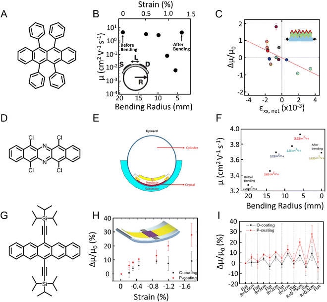 | ||
| Fig. 25 (A) Crystals of rubrene exhibit (B) stable device performance up to 0.74% strain.341 Adapted with permission from ref. 341 Copyright 2006, Wiley-VCH. (C) Wrinkled rubrene crystals show mobility changes depending on whether the local strain is tension (decreased mobility) or compression (increased mobility) deformation.352 Adapted with permission from ref. 352 Copyright 2015, Springer Nature. (D) TCDAP crystals under (E) compression resulting in (F) increasing mobility and partial recoverability of device performance after bending.353 Adapted with permission from ref. 353 Copyright 2016, Jove. (G) Films of TIPS-P exhibit increasing mobility under compression (H) and reliable recoverability under multiple cycles, systematically decreasing the bending radius (I).354 Adapted with permission from ref. 354 Copyright 2018, Wiley-VCH. | ||
To understand this underlying effect in TCDAP (Fig. 25D), Ho and Tao et al.353 compared their bending device (Fig. 25E) with the crystallographic direction of TCDAP, showing that the bending occurred along the π-stacking direction. This suggested that the increase in mobility during compression (Fig. 25F) was a result of increased charge transfer integral potentially due to a closer π–π stacking distance or increased π-overlap. Interestingly, while both the rubrene and TCDAP crystals compressed along the π-stacking direction within the crystal, the TIPS-P (Fig. 25G) case was based on films without one alignment direction, suggesting that this trend is not based solely on local changes in the packing. Lai, Mas-Torrent et al.354 showed that bending in both the parallel and orthogonal (Fig. 25H, red and black lines, respectively) directions with respect to printing, affected the strain only slightly, while compression resulted in lower contact resistance. This effect resulted in a cyclable bending device with recoverability even at bending radii down to 0.5 cm (Fig. 25I). This shows that the impact on semiconducting performance during bending is multifaceted with dependencies beyond local structural changes.
To better understand strain on charge carrier mobility, structural studies highlighting changes in the molecular packing during bending have been of fundamental importance. Specifically, applied strain requires distortions in the crystal structure to accommodate expansion or contraction. Although the distortions are typically small, even small changes in packing can lead to large effects on charge transport properties. In many systems, compression and stretching result in changes in the molecular spacing along the charge transport direction, causing changes in the molecular coupling between nearest neighbors.353 Wu and Frisbie et al.350 investigated the local change in the electronic structure during strain application using scanning Kelvin probe microscopy to measure the change in the work function (ΔWF). By heating crystals of rubrene attached to either PDMS or silicon substrates, the crystals would experience tension or compression, respectively, along the π-stacking direction due to a mismatch in the thermal expansion coefficient (Fig. 26A and B). In a similar fashion to the impact on mobility, the work function was found to decrease up to 100 meV under a compressive strain of −0.1% and increase greater than 200 meV under a tension strain of 0.125% (Fig. 26C). The decrease in the WF under compression was attributed to an increase in coupling of π–π interactions induced by the compressive strain and the opposite under tensile strain. Moreover, during tension, the slope of this work function increased above 0.05% strain. However, no significant morphological changes such as cracks were observed, suggesting an elastic to plastic deformation transition. This effect even manifested through measured hysteresis during compression, shown in Fig. 26D. This switch between elastic and plastic deformation significantly impacted the magnitude of the change in the WF, with the elastic deformation regime only decreasing the WF by 20 meV whereas plastic deformation decreased the WF by 200 meV.
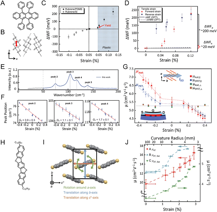 | ||
| Fig. 26 Rubrene (A) showed strain along the (B) π–π stacking direction caused (C) local change in the work function with strain.350 Adapted with permission from ref. 350 Copyright 2016, Springer Nature. (D) This effect was more pronounced during plastic deformation and showed hysteresis. Under compression, (E) phonon vibrational modes observed under Raman spectroscopy underwent (F) blue shift, consistent with phonon hardening.349 Adapted with permission from ref. 349 Copyright 2019, Wiley-VCH. (G) Resulting devices exhibited increased mobility. (H) C10-DNBDT-NW under compression (I) exhibits reduced molecular vibrations. (J) Suppressed vibrations results are correlated with the changes in mobility, increasing (decreasing) upon compression (tension).348 Adapted with permission from ref. 348 Copyright 2016, Springer Nature. Mobilities were measured along the c axis for 3 devices in both 4 terminal (A, red) and 2 terminal (B and C, blue and green, respectively) configurations. | ||
Recently, Choi and Podzorov et al.349 showed that more than simple structural modulation occurs in strained rubrene crystals. Using Raman spectroscopy to investigate the low-frequency vibrational modes, they observed a strong correlation between the applied strain with the phonon mode peak positions. With increasing tensile strain, the low frequency peaks uniformly blueshift by 1 or 2 cm−1 under −0.4% uniaxial compressive strain (Fig. 26E and F). This hardening of phonon vibrations followed the mobility measured from both OFET devices and the quantum Hall effect: the mobility increased by a factor of 1.5 with increasing compression (Fig. 26G). These results fit quite nicely with an earlier study by Kubo and Takeya et al.,348 who studied the effect of strain on the dynamic disorder in crystals of C10-DNBDT-NW (Fig. 26H). During application of strain via compressive bending to a 3% strain, the π–π stacking direction (c axis) exhibited a similar 3% decrease in length. At the same time, DFT simulations of this change showed a clear reduction in molecular vibrations under these conditions, decreasing the amplitude of translations in the c* and b directions by 8.7–16% (Fig. 26I, orange and blue arrows) and decreasing rotations around the a direction by 7.5% (green arrows). This suggests an overall reduction in the dynamic disorder leading to the substantial 70% increase in mobility (Fig. 26J, red line) under the 3% strain. A decrease in molecular distance along the π–π stacking direction leads to a synergistic decrease in the molecular vibrations, resulting in exceptional strain-responsive devices.
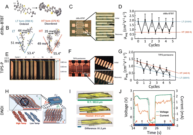 | ||
| Fig. 27 (A) ditBu-BTBT shows a cooperative phase transition triggered by an order-to-disorder transition in the tert-butyl groups. This results in a (B) 2° change in the herringbone angle50 which, despite the small change, causes the charge transfer integral between neighbors to decrease substantially, and (C) resulting OFET devices (D) show charge carrier mobility modulated by 217% between states over many cycles.50 (E) TIPS-P shows a similar polymorphic phase transition that is coupled with a 10% elongation of the crystal. (F) Thin film devices exhibited (G) switching of the charge carrier mobility between the high and low temperature phases that evolves with multiple cycles.50 Adapted with permission from ref. 50 Copyright 2018, Springer Nature. (H) Crystals of NDI derivative also undergo a thermally induced phase transition, as a result of changing molecule tilt, causing a (I) similar length change that was harnessed for (J) a robust actuator device.355 Adapted with permission from ref. 355 Copyright 2021, American Chemical Society. | ||
Intriguingly, cooperative, martensitic transitions in molecular crystals of TIPS-P can be triggered by applying a mechanical force, leading to superelasticity and ferroelasticity observed for the first time in organic semiconductors. Park, Diao et al.97 showed that a TIPS-P crystal held near the phase transition temperature undergoes rapid switching between polymorphs upon application and release of [100]-shear loading (i.e., superelasticity). The mechanical stress was also accompanied by a significant shape change (Fig. 28A and D), previously shown to be thermally triggered.50 In a similarly cooperative fashion, TIPS-P also exhibited cooperative twinning upon stretching of the crystal or [100] shearing at room temperature. Unlike the previous structural transitions, twinning preserves the same molecular packing in both the mother and daughter crystal (i.e., ferroelasticity), but introduces new domain boundaries which accommodate significant strain (Fig. 28B and E). Remarkably, they demonstrated, in the case of ferroelasticity, that 70% of the charge carrier mobility is preserved under as much as 13% strain (Fig. 28C). Not only does ferroelasticity maintain performance under high strains, but the twinning process is also reversible, showing no signs of degradation even after multiple cycles up to 2.5% strain (Fig. 28F). This work establishes mechanically induced cooperative transitions as a new stress-releasing mechanism for highly deformable single crystal electronic devices.
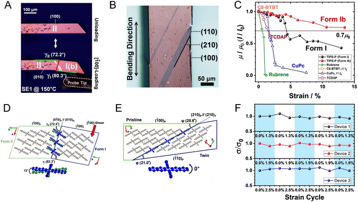 | ||
| Fig. 28 TIPS-P phase transition coupled with [100] shearing applied to the crystal (A and D) and twinning coupled with stretching (B and E) exhibiting superelasticity and ferroelasticity, respectively. Device performance under stretching showed (C) stable charge carrier mobility in TIPS-P crystals up to 5% strain in form I and even higher strains in form Ib along (F) with high recoverability across 5 cycles.97 Adapted with permission from ref. 97 Copyright 2020, Wiley-VCH. | ||
5.3. Prospects and opportunities
Organic molecular crystals have shown extraordinary mechanical effects that range from elastic and superelastic deformability to self-actuation. The discovery and application of these effects in organic semiconductors in recent work have led the way to the novel electronic design of flexible electronics based on organic crystals. The easy access to deformability in organic semiconducting molecular crystals offers a unique advantage over inorganic counterparts in realizing wearable electronics. Moreover, the discovery of highly sensitive molecular crystals to strain provides a platform to confer additional functionalities for sensor-based devices. The nature of this sensitivity has been elucidated for several systems, suggesting the importance of molecular packing changes occurring during device bending. Coupling structural transitions in recent works have expanded the horizons for the functionality of these systems, pushing the limits of strain accommodation past 10% in organic semiconductor crystals. However, intentional access of specific bending modes and tuning their effect on electronic properties still remains elusive.6. Application of molecular crystals as optical waveguides
6.1. Introduction to single crystal optical waveguides
An optical waveguide, in which light is transmitted internally through total reflection at the interface of an optical medium is a fundamental and pivotal composition of various devices in integrated optical circuits.356,357 Optical waveguides include both long-distance optical waveguide fibers and short waveguides in centimeters, such as optical waveguides prepared from crystalline materials. Conventional optical waveguides, made of silica or polymers, are the primary media for fast, efficient and long-distance data transmission up to tens of thousands of kilometers. Nevertheless, they are rarely used for short-range micro/nanoscale data transmission. Organic crystals are viable candidates for the next-generation optical waveguides due to their high refractive index, variable chemical composition, uniform morphology, good thermal stability, and high photoluminescence (PL) efficiency.358–360The structure of optical waveguides consists of a waveguide layer with a relatively high refractive index and a substrate and cover layer with a relatively low refractive index. Ideally, light escapes neither to the cover layer nor to the substrate and is completely confined to the waveguide with no attenuation of energy, in which the corresponding transmission mode is called a “guided mode” to describe the distribution of light energy in one-dimensional or multidimensional space. It should be noted that two factors are required to form an optical waveguide: total reflection and a medium with a higher dielectric constant/refractive index than that of the external environment.361 Total reflection occurs when light propagates from a medium with a higher density to a medium with a lower density, and the incident angle is greater than the critical angle.362 Therefore, the light field can be well confined in the micro/nanoscale structure. Organic crystals based on small organic molecules have excellent crystallinity and are devoid of grain boundaries, properties that are beneficial to light transmission. In addition, single crystals of π-conjugated organic molecules can be used as high-performance optical waveguides due to their alignment and dense packing.
Devices include passive and active optical waveguides. Passive optical waveguiding refers to the transmission of an unaltered (except for decreased intensity) incident light, while active waveguiding is the transmission of the material's fluorescence obtained via excitation with the incident light. In recent years, optical waveguide properties naturally generated from organic molecule crystals have been widely studied to realize both passive and active optical transmission.363–369 For example, Döbeli et al. incorporated H+ ions in an organic crystal to achieve a refractive index suitable for optical waveguides.363 This work provides a new prospect for the application of ion implantation to integrated optics, and for the first time, to organic crystals. Fu et al. fabricated both perylene 1D ribbon-like and 2D square-like crystals into waveguides.364 This excellent example shows that the optical waveguide of an organic crystal can be adjusted by controlling the dimension of the crystal during synthesis. Subsequently, an increasing number of organic crystals with varied structures and morphologies have been synthesized and applied to various optical devices due to their excellent optical waveguide properties.370–375 These studies have demonstrated broadband signal transmission from visible light to other regions, anisotropic response, and low optical loss (down to about 0.1 dB mm−1) for organic crystals, all of which are promising for optoelectronic applications.
6.2. Flexible organic crystal optical waveguides
The majority of organic crystals are commonly stiff, brittle and tend to crack into pieces or powders under external pressure. This is mainly due to the regular arrangement of atoms, forming an ordered and stable structure. The mechanical properties greatly limit the use of organic crystals in practical applications, and especially in flexible electronic and optical devices. Therefore, organic crystals with exceptional mechanical flexibility5,29 have attracted extensive attention and emerged as flexible optical media for high-performance waveguides. Flexible organic crystals have been already shown to be favorable waveguides.370,376–395 In 2018, Zhang et al. reported a centimeter-sized elastic crystal of (E)-1-(4-(dimethylamino)phenyl)iminomethyl-2-hydroxyl-naphthalene (DPIN).370 Having a relatively planar donor–acceptor structure, DPIN possesses bright emission and high elasticity in crystalline state. A flexible optical waveguide based on the high elasticity and luminescence of a DPIN crystal was first proposed and implemented (Fig. 29A–I). Subsequently, a self-waveguiding organic crystal with excellent ultralow temperature elasticity was prepared by the same group.386 The crystal exhibits elasticity and is an excellent optical waveguide even at −196 °C (Fig. 29J–S). These results indicate the application potential of the single-crystal materials in flexible optical/optoelectronic devices in unconventional and extreme environments.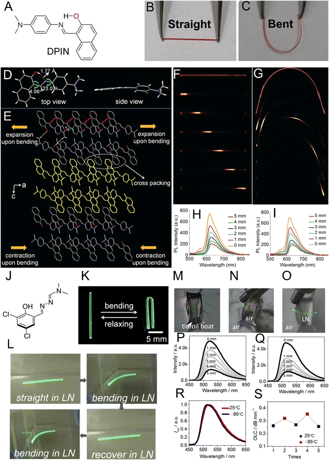 | ||
| Fig. 29 (A) Chemical structure of DPIN. (B) Straight DPIN crystal and (C) elastically bent DPIN crystal that has been bent by applying mechanical force. (D) Crystal structure of DPIN. (E) Molecular packing in the (010) plane (the red arrows, green dashed lines and yellow lines represent the π–π, C–H⋯π and C–H⋯O interactions, respectively). (F and G) Excitation position-dependent fluorescence (FL) images of (F) straight and (G) bent crystals. (H and I) Corresponding fluorescence spectra of (H) straight and (I) bent crystals. Adapted with permission from ref. 370 Copyright 2018, Wiley-VCH. (J) Chemical structure of a compound used to study the temperature dependence. (K) Bending–relaxation (L) images of repeated bending experiments of a single crystal in liquid nitrogen (LN) under UV light. (M–O) Images of (M) tin foil boat, a bent crystal excited using a 355 nm laser from the left of (N) empty boat and (O) boat filled with liquid nitrogen. (P and Q) fluorescence spectra collected at one end of the crystal at (P) 25 °C and (Q) −95 °C. (R) Emission spectra of crystals at 25 °C and −95 °C. (S) Optical loss coefficients (OLC) of the same crystal determined by thermal switching between 25 °C and −95 °C. Adapted with permission from ref. 370 Copyright 2020, Wiley-VCH. | ||
Mechanical deformations can be polymorph-dependent. Zhang et al. reported a crystalline molecular material, dimethyl 2,5-bis((thiophen-2-ylmethyl)amino)terephthalate, that has two polymorphs, Cry-R and Cry-O.379 Cry-O can be elastically bent, almost into a loop, and acts as optical waveguide in both straight and bent state. The other polymorph, Cry-R, forms both naturally bent crystals and even forked crystals with optical waveguides as efficient as that of the straight crystal. Naumov et al. reported an azo compound, 3′,4′-dimethyl-4-(dimethylamino)azobenzene (DDAB), which combines mechanical response and optical waveguide properties for spatial photocontrol over the optical output.309 DDAB crystals can be controlled through reversible photoswitching between the trans and cis isomers on the irradiated crystal surface. The passive optical waveguiding capability of the crystal remains unaffected by its deformation induced by exposure to UV light, which successfully demonstrated that photobendable organic crystals can efficiently transduce light while maintaining their dynamic function. This is the first case of two-dimensional spatial photocontrol of the optical output of an organic crystalline waveguide. In addition, Zhang et al. reported a dual stimuli-responsive bendable organic crystal of (Z)-4-(1-cyano-2-(4-(dimethylamino)phenyl)vinyl)benzonitrile (CN-DPVB).385 The crystal is very elastic and bends noticeably when exposed to hydrochloric acid vapors. Millimeter-size crystals of CN-DPVB, in both straight and bent states, were tested as low-loss optical waveguides. This study showed the utility of chemical means to control the shape of crystals. Flexible optical waveguides from plastically bendable organic crystals have also been extensively studied owing to their extraordinarily mechanical compliance.381,389 For example, Naumov et al. prepared an anthracene derivative, 9,10-dicyanoanthracene (DCA) which has both active and passive waveguiding properties in a plastic bent state (Fig. 30).381 The straight and bent DCA crystals displayed green emission with three bands (530, 570, and 610 nm) upon excitation (365 nm). The excited position emitted green light, while both ends of the crystal emitted orange-red light, which is an evidence of active waveguiding (Fig. 30E and F). When the crystal was excited with 635 nm light, the spectrum of the transmitted light was retained, which is an evidence of passive waveguiding (Fig. 30G and H). Altogether, this and many other examples demonstrate that flexible crystals have excellent optical transmission capability, while they are also flexible. These results have important implications for practical applications, for example, in multiply bent, flexible or complex optoelectronic devices. In addition, a combination of polymer materials and organic crystals has also been suggested to prepare organic crystals with sustained optical waveguiding properties.396 The most recent research on hybrid crystal–polymer materials has expanded significantly both the range of stimuli that can be used to control the shape of organic crystals and the kinetics of their operation as dynamic optical waveguides.
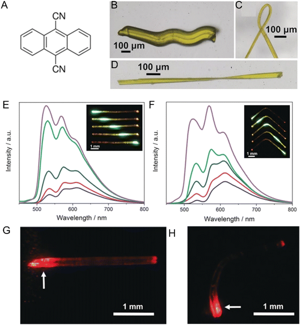 | ||
| Fig. 30 (A) Chemical structure of 9,10-dicyanoanthracene (DCA). Plastic deformation of DCA crystals, shown as (B) multiple bending, (C) bending over 180°, and (D) twisting. (E and F) Fluorescence spectra recorded at the terminal of the straight (E) and bent (F) DCA crystals when the crystal was excited at different positions. The fluorescence images are shown in the insets. (G and H) Photographs showing the transduction of 635 nm light through the crystal before (G) and after bending (H). Adapted with permission from ref. 381 Copyright 2018, Wiley-VCH. | ||
The flexible organic crystalline waveguides discussed above typically have dimensions in the centimeter range. Miniaturized devices such as nanophotonic devices require nano-sized optical waveguides as one of their most important components.397–399 However, due to their small size and brittleness microcrystals are generally difficult to handle. Micromanipulation using an atomic force microscope (AFM) cantilever can be used80,378,395 to deform microcrystals without damage. Chandrasekar et al. proposed a method for precise control of the longitudinal size of self-assembled organic nanotubes.400 A combination of laser confocal Raman and atomic force microscopes was employed to perform laser ablation/cutting and waveguiding experiments.80 Recently, the same group in collaboration with others reported microcrystals of dithieno[3,2-a:2′,3′-c]phenazine (SYN) with mechanical flexibility for wavelength-division multiplexing (WDM) (Fig. 31).378 When pressed with an AFM cantilever tip, the microcrystals deposited on the glass surface behaved like plastic crystals, due to the strong adhesion between the surface and the crystals. The efficient transmission of optical signals of different fluorescence colors by the flexible crystal waveguides (straight or bent), showed that the SYN crystals are suitable for WDM (Fig. 31A–D). A 2 × 2 directional coupler with two inputs and outputs was constructed from two bent waveguiding crystals that were conjoined by micromanipulation. Optical coupling at either end of the crystal converts fluorescence to the other end of the crystal, and the output intensity of the two signals passing through the two waveguides is related to the optical path length (Fig. 31E–H). This mechanical micromanipulation approach can also be effectively applied to other flexible microcrystals to design and construct complex photonic circuits. Meanwhile, Chandrasekar and Naumov groups have jointly demonstrated an effective and non-destructive method for manipulation of microcrystalline optical waveguides.80 By using this method, mechanically compliant single microcrystals can be precisely bent, repositioned, and split.
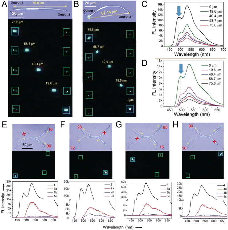 | ||
| Fig. 31 (A,B) Confocal optical micrographs of (A) nearly straight crystals (B) that were bent into an arc. Fluorescence images of the microcrystals transducing light when excited at different positions are also shown. (C,D) Fluorescence spectra of (C) straight and (D) bent crystals collected at the end of the crystals excited at different positions. (E–H) From top: confocal optical microscopy, fluorescence images and spectra of two coupled crystalline waveguides acting as a 2 × 2 directional coupler when excited at any one of the four termini. The red crosses indicate absence of light output. The yellow arrows show the light propagation paths. The red numbers indicate the path-dependent spectral ratio of the directional coupler. Adapted with permission from ref. 378 Copyright 2020, Wiley-VCH. | ||
There are still many challenges to be solved towards practical applications of organic crystal waveguides. The speed of information processing is a key parameter and performance index of the future optoelectronic integrated devices. Molecular components of crystals and their photophysical properties, e.g. optical band gaps and charge separation, must be properly selected and designed to obtain a reliable high-velocity response. To realize integrated optimization of device geometries, the controllability of crystal shape is a basic requirement. Moreover, it is necessary to improve the control of the optical coupling between the photoconductive medium and the integrated device. Altogether, flexible organic crystals appear as an ideal choice for the fabrication of complex optoelectronic devices.
6.3. Amplified spontaneous emission (ASE) in flexible organic crystals
Compared to ordinary light sources, lasers with conspicuous monochromaticity, directionality and high brightness are widely applied in various fields such as medicine, telecommunications, and national defense, and even in our daily life, including printers, barcode readers, and video and audio players. The laser generally consists of three parts: a pumping source, an optical gain medium and an optical resonator. The presence of a gain medium that amplifies light is a necessary condition for the generation of laser light.401 The amplification of light originates from the stimulated radiation process of organic luminescent materials. When the medium is excited with an incident beam of light, the excited particles jump to the ground state and emit photons that have the same phase, frequency, polarization and direction of propagation as the incident photons, which means that the original incident light has been amplified. The amplified light produced by this phenomenon of stimulated emission is laser light.Organic solid-state lasers (SOLs) that have the advantage of easily adjustable fluorescence, high absorption cross-sectional area, flexibility, and light weight are of interest to laser research.401 Considering their good processing properties, applicable substrates and wide spectral range, organic luminescent solids hold a great potential for the development of organic lasers. Although solid organic lasers have been widely used, research on organic crystal-based lasers is still rare due to the difficulty with obtaining high-quality crystals of appropriate size and shape with high fluorescence efficiency. In 1997, Fichou demonstrated the phenomenon of amplified stimulated emission (ASE) of an α-oligothiophene single crystal.402 Under single-photon pumping, dual-energy dependence of two distinct emission lines and low threshold gain narrowing were observed, which resulted from a net alignment of molecular dipoles in a crystal having the dimensions and optical quality of a resonator. For organic crystals, crystal quality, molecular packing and intermolecular interactions have important effects on the behavior of ASE.403,404 Until now, ASE properties have been identified in various organic crystals with different molecular structures, including thiophene–phenylene co-oligomers (TPCOs), oligophenylene vinylenes (nPVs), anthracene and chalcone derivatives.405–418 For instance, Wang et al. have reported two new molecules with amplified spontaneous emission.406,407 Four kinds of crystals with different fluorescence emissions from green to orange were obtained from 4,4′-(thiazole[5,4-d]-thiazole-2,5-diyl)bis(N,N-diphenylaniline) (PTATA) by varying the crystal growing conditions.406 Only the green-light-emitting PTATA crystal exhibits great potential in organic lasers due to its low threshold ASE character whereas other crystalline phases do not show this phenomenon. Additionally, two polymorphs 1R and 1O, with quite different emissions, were prepared based on a very simple organic ESIPT-active molecule, (E)-3-(4′-dimethylaminophenyl)-1-(4′-fluoro-2′-hydroxyphenyl)-2-propen-1-one.407 Crystals 1R and 1O display significantly narrowed and amplified emissions, thus providing a rare example of polymorph-dependent ASEs. Recently, a wide-wavelength tuning approach of organic micro/nanolasers was established by Dong et al.410 The output lasing wavelengths of 2,5-bis(4-biphenylyl)thiophene (BP1T), doped with a controllable amount of 5,5′′-bis(4-biphenylyl)-2,2′:5′,2′′-tetrathiophene (BP3T), were switched across all vibronic bands covering the entire emission spectrum. The results indicate a promising path for rational design of miniaturized lasers and other photonic components with similar performance.
Although organic crystals have drawn immense attention for their attractive applications in laser photonics in recent decades, the future implementation of flexible organic crystals in optical devices, such as crystal lasing devices, remains a formidable challenge.402,403,419 In 2012, Sun et al. fabricated ultrathin organic single crystals of 1,4-bis(4-methylstyryl)benzene (BSB-Me) that were used as active lasing media in distributed feedback laser devices.420 The thin single crystals were extended onto bendable poly(ethyleneterephthalate) (PET) substrates and a flexible organic single-crystal distributed feedback (DFB) laser was constructed. The results promise the development of low-cost and flexible crystal lasers. Zhang et al. have conducted in-depth studies on flexible ASE crystals in recent years.379,382,391 In 2018, they reported the elastic organic crystals 1d@2d, prepared by doping 2,5-dihydro-3,6-bis(octylamino)terephthalate (host 1d) with 3,6-bis(octylamino)terephthalate (guest 2d).382 The potential application of 1d@2d as flexible crystal lasing medium was revealed by ASE measurements, and the threshold value of bent crystals of 1d@2d was determined to be 115 kW cm−2, which is comparable to that of a straight crystal (Fig. 32). The doping method combines the advantages of 1d and 2d for making doped crystals 1d@2d with excellent elasticity and strong orange fluorescence. The potential of these doped crystals was evaluated by measuring amplified spontaneous emission in straight and bent states. Crystals of Cry-O mentioned in the previous section379 are also good candidates for flexible crystal lasing media. The results indicate that light was perfectly confined and amplified by stimulated emission inside the highly bent Cry-O crystals, and the threshold value was determined to be 107 kW cm−2. Very recently, a diaryl β-diketone with three different emissive organic polymorphs was reported.391 Cry-G and Cry-Y exhibit ASE, and Cry-G does so when bent. These results could guide the development of crystal flexibility by structure engineering and provide models of flexible organic crystals for multifunctional application in flexible laser devices.
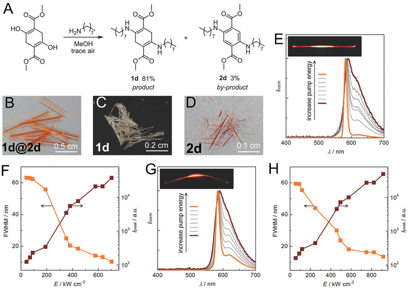 | ||
| Fig. 32 (A) Synthesis of crude 1d containing 2d as an oxidized byproduct. (B–D) Photographs of crystals 1d containing 2d (1d@2d), 1d and 2d. (E and G) Emission spectra of straight (E) and bent (G) crystals as a function of the pump laser energy. Photographs of the crystal under the excitation of a pump laser are shown in the inset. (F and H) Dependencies of the fluorescence intensity and full-width half-maximum (FWHM) on the pump laser energy for straight (F) and bent (H) crystals. Adapted with permission from ref. 382 Copyright 2018, Wiley-VCH. | ||
Low ASE thresholds have been demonstrated based on some specific structures, such as fluorene, anthracene and p-phenylene vinylene derivatives. However, there is no well established theory to determine whether a particular organic crystal possesses ASE characteristics. The development of effective methods to detect the high gain medium of organic lasers, especially the electrically pumped fiber lasers, remains a great challenge. For the prospective application of electrically pumped organic lasers, there are several critical requirements as to the gain media. An extremely low threshold means that a low current density is required under electrically pumped conditions. A high optical gain coefficient can compensate for the optical loss of the electrically pumped equipment, and high thermal and optical stability is required to ensure long-term operation of the equipment. The mechanical bendability and machinability allow the crystal laser architecture to be flexibly adjusted.404,421
6.4. The physics of single-crystal optical microwaveguides, resonators and photonic integrated circuits
Organic crystal-based optical components, viz., optical waveguides,309,359,370,372,385,400,422–426 resonators,427–429 modulators,430 circuits,378 and lasers419,431 are essential for construction of future organic nanophotonic devices.432 Organic optical crystals offer high exciton (electron-hole) binding energy, room temperature-stable exciton-polariton (EP),433,434 optical bandwidth tunability (from UV to NIR), high refractive index ( ; where εr is the dielectric constant), optical nonlinearity (χ(2 or 3) where χ is electric susceptibility and the superscript denotes the order),427–429 responsiveness to stimuli,309,430,435 and mechanical flexibility.80,370,422,426
An optical waveguide can be classified as either active309,370,372,422,424,425 or passive.359,423 The first active type flexible microwaveguide based on 3-ethyl-2-[(3-ethyl-2(3H)-benzothiazolylidene)methyl] benzothiazolium iodide (thiacyanine, TC) was reported by Takazawa et al. in 2015.424 Later, the first flexible, passive type crystal waveguide based on 4,4′-bis(2,6-di(1H-pyrazol-1-yridinedin-4-yl)biphenyl that transduces light at any acute angle was reported by Chandrasekar et al. in 2013.426 Both types of waveguides are important for organic integrated photonic circuits (OPICs). Typically, the input light couples to a high refractive index optical waveguide after meeting the total internal reflection (TIR) condition (Fig. 33A), i.e., when the angle of the incident light (θ1) is greater than the critical angle (θc). An example of light transmission within an organic crystal waveguide (n2) via TIR is shown in Fig. 33A. An evanescent field penetrates towards the low-refractive medium (n1) during the light reflection, and it decays exponentially from the interface. The evanescent field couples the two optical waveguides, excites a resonator, near field interaction, and powers a device wirelessly.
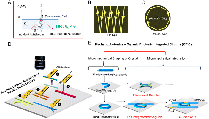 | ||
| Fig. 33 (A) Total internal reflection condition and exponentially decaying evanescent field formation. (B) Light reflection in Fabry–Pérot (FP) resonators, and (C) circulation in whispering–gallery–mode (WGM) resonators. The inset shows the equation for the resonance condition. (D) Schematic representation of micromechanical operations involved in the AFM-based micromanipulation under a confocal microscope. (E) The proposed mechanophotonics approach towards the fabrication of single-crystal-based OPICs. Adapted with permission from ref. 80 Copyright 2020, Wiley-VCH, adapted with permission from ref. 378 Copyright 2020, Wiley-VCH and ref. 400 Copyright 2014, The Royal Society of Chemistry. | ||
In waveguides, light propagates as modes in finite numbers. Depending upon the diameter of the guiding medium, it can transduce single-mode or multimodal light. By assuming the transverse magnetic (TM) modes of light (in the x,y plane), the number (m) of propagating optical modes in a rectangular waveguide with uniaxial dielectric parallel and perpendicular components can be determined by using the following relation:419
 | (9) |
 | (10) |
| Itip = Ibodye−αd | (11) |
In optical resonators, an evanescent field is essential to couple two photonic elements (e.g., two waveguides or a waveguide and resonator) optically when they are in physical contact (typically with their separation not longer than λ/2). An excellent example of a device based on evanescent field coupling is the directional coupler.437 This evanescent field can be also used to construct crystal-based OPICs.438–440 Microscale optical waveguides (straight and bent) and resonators are essential components of miniature OPICs. In this context, mechanically flexible (bendable) microcrystal waveguides are important because the circuit demands manipulation of photons in different directions and at various angles. Splitting, modulating (phase/intensity), filtering, lasing, coupling and detecting light are some of the functions that can be realized in OPICs by integrating flexible crystal waveguides (passive/active), resonators, and modulators.439,440 The high thermo-optic coefficient (temperature dependence of n) of silicon-based PICs441 makes them sensitive to slight deviations from circuit geometry; therefore, OPICs could be a good substitute for silicon-based circuits.442
6.5. Mechanophotonics
6.5.1.1. Crystal moving and lifting. The lifting of a crystal from the substrate is a vital micromanipulation operation. This operation helps to move the selected crystal to the substrate's desired location and to transfer a crystal from one substrate to another for integration. The first example of mechanical manipulation of a microcrystal waveguide was performed using a BPP microcrystal waveguide in 2014 (Fig. 34A).400 The crystal was lifted from the substrate using an AFM cantilever tip (Fig. 34B–D). The experiment was initially intended to demonstrate the efficient passive waveguiding ability of a crystal even when it is lifted from the substrate and surrounded by air (n = 1).
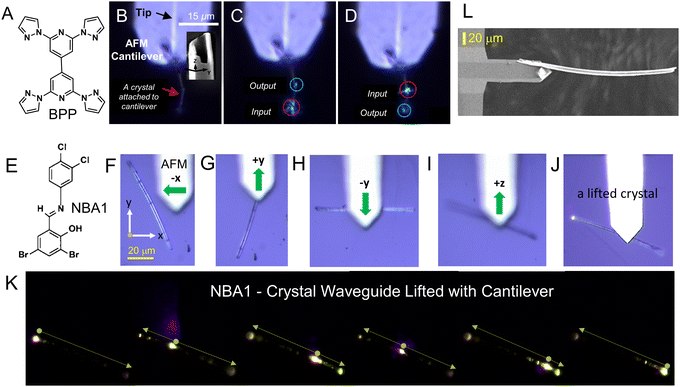 | ||
| Fig. 34 (A and E) Molecular structure of BPP and NBA1. Optical micrographs of a (B) bent crystal attached to an inverted AFM cantilever (the inset shows the FESEM image of a tubular crystal tip) and (C and D) passive optical waveguiding behavior of the bent crystal. Optical micrographs of a (F) crystal on the substrate, (G) movement of the cantilever towards the crystal, (H) crystal being pulled by the cantilever in the backward direction and (I) then pushed forward to connect it to the tip, and (J) finally being lifted. (K) Fluorescence images of a single crystal lifted using the cantilever, excited at different positions. The broken yellow arrows show the direction of light propagation. (L) FESEM image of the crystal attached to the cantilever. Adapted with permission from ref. 80 Copyright 2020, Wiley-VCH and ref. 400 Copyright 2014, The Royal Society of Chemistry. | ||
In 2020, the same experiment was performed with a flexible crystal of N-benzylideneaniline derivative, abbreviated NBA1 (Fig. 34E).80 The optical images displaying steps that are involved in lifting a single crystal from the substrate using an AFM cantilever are presented in Fig. 34F–J. The first step was attaching the crystal to the tip using tip-crystal attractive forces. The cantilever was then moved back and forth over the crystal, attaching the crystal to the tip (in this particular case, −x, +y and −y directions). The cantilever carrying the crystal was slowly lifted (+z direction), as shown in Fig. 34F, G and L. The lifted crystal also efficiently transduced the fluorescence to its tips, confirming the retention of its optical waveguiding properties (Fig. 34K).
6.5.1.2. Crystal cutting and bending. Another essential micromechanical operation is crystal cutting, as it is useful for making optical waveguides of defined lengths suitable for precise OPIC fabrication. The first cutting operation of a DCM dye-based FP crystal to alter the cavity length was also performed with an AFM cantilever (Fig. 35A–D).443NBA2 crystals obtained from a derivative of N-benzylideneanilines also exhibit mechanical flexibility (Fig. 35E–G). It was expected that tilting of the π–π stacked (4.464 Å) molecules along with the sliding neighboring molecules drives the compression (concave side) and expansion (convex side) of the bent section of the crystal (Fig. 35G). The Young's modulus of NBA2 is 0.53–0.61 GPa on the (010) face, as measured by performing the three-point bending test. Applying a force perpendicular to the crystal's longest axis separated the crystal into two pieces (Fig. 35H–J).80 One of the straight crystals (L ≈ 163 μm) was bent to an angle α ≈ 12° by pushing its right side by using an AFM tip (Fig. 35L). Remarkably, the bent (elastic) crystal retained its bent shape due to surface adhesion (Fig. 35M). Both the left and right ends of the crystal were then bent to angles of α ≈ 34° and 43°, respectively, to realize an arc-shaped crystal (Fig. 35M–P). The FESEM examination of another NBA2 bent crystal's (chord ≈ 115 μm) body and termini showed no visible defects (Fig. 35Q). Single-particle microspectroscopy revealed the microcrystal's optical waveguiding properties before and after bending (Fig. 35R and S). To estimate the optical loss coefficients of waveguides before and after mechanical bending, the excitation-position-dependent fluorescence spectra were collected by varying the optical path length. Subsequent analysis of the spectral data using eqn (3) showed only a slight variation of 0.00207 dB μm−1 in the estimated α, indicating a very small bending-induced optical loss (Fig. 35T).
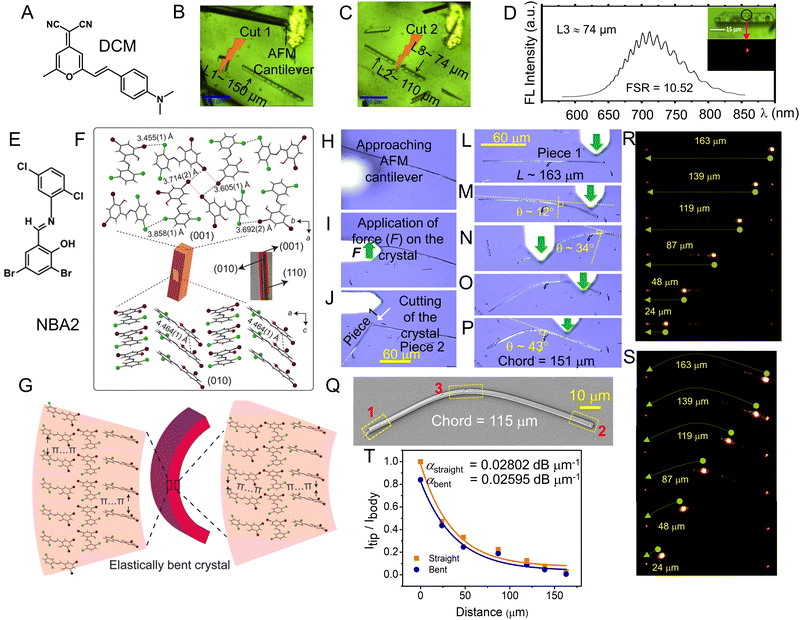 | ||
| Fig. 35 (A and E) Molecular structures of DCM and NBA2. (B and C) Cutting of a long microrod into three different lengths using an AFM cantilever tip. (D) FP resonances from a microrod of length ∼74 μm. The insets show their corresponding bright and fluorescence field images before and after laser excitation, respectively. (F) Molecular packing in a crystal of NBA2 viewed perpendicular to their (010) and (001) faces. (G) Schematic diagram showing the mechanism of elastic bending of a NBA2 crystal. Confocal optical micrographs of (H) an AFM tip approaching the crystal, (I) application of force at the middle of the crystal, which results (J) in breaking of the crystal into two pieces, and (L–P) bending of one of the pieces of length L ≈ 163 μm by alternative applications of force at both ends of the crystal. (Q) FESEM images of a bent single crystal. (R and S) Fluorescence images of straight and bent crystals of NBA2 transducing light when they are excited at different positions. (T) Plot of the intensity ratio at the tip and the body of the crystal (Itip/Ibody) versus the distance of light propagation used to estimate the optical loss coefficient (α). Adapted with permissions from ref. 80 Copyright 2020, Wiley-VCH and ref. 443 Copyright 2016, Wiley-VCH. | ||
6.5.1.3. Crystal slicing and double bending. Crystal slicing is a vital micromanipulation operation that detaches single crystals from microcrystalline aggregates. This operation was demonstrated by taking three bundled NBA2 crystals (Fig. 36A).80 The crystals’ left side was segregated by pressing the AFM cantilever tip against the troughs between the crystals on the left side and moving back and forth perpendicular to the crystal axis (Fig. 36B). Due to their flexibility, the crystals bent and partially separated on the bundle's left side while they remained attached to its right side. Each crystal could be bent further by the AFM tip (Fig. 36C), and the crystals transduced fluorescence in different directions (Fig. 36B and C). Sliding the cantilever along the long axis from the left to the right end of the bundle completely separated one of the bent crystals (Fig. 36D). The separated bent crystal regained its straight shape, confirming the crystal's elasticity when there is no contact with the substrate. Furthermore, the remaining attached crystals could be manipulated to create a doubly bent crystal (Fig. 36E). Schematic representation of the steps involved in the operation is shown in Fig. 36F.
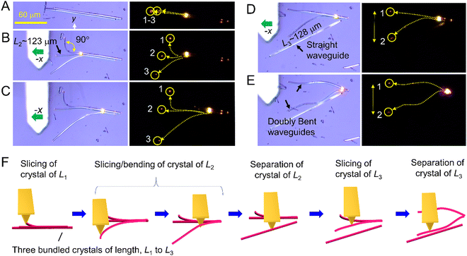 | ||
| Fig. 36 (A–E) Confocal optical micrographs (left) and the respective fluorescence images (right) of three bundled crystals that were later partially or completely separated by slicing, cutting and bending operations. (B and C) Partial separation of crystals by means of slicing and (D) separation of a crystal from the bundle. (E) Mechanical bending at multiple points to obtain a crystal with an undulated shape. The broken yellow arrows in all fluorescence images indicate the direction of light propagation. (F) Cartoon representation of slicing and bending operations. Adapted with permission from ref. 80 Copyright 2020, Wiley-VCH. | ||
6.5.1.4. Crystal lifting, transfer, and alignment/integration. Transferring crystals from one substrate to another is an essential micromechanical operation for fabricating hybrid OPICs with two or more chemically (electronically) or mechanically different crystals.438 For example, DPIN crystals (Fig. 37A) are mechanically flexible to an extent that extremely curved geometries, almost circular, can be prepared. The flexibility of DPIN and BPIN crystals presumably arises from the expansion and contraction of crisscross-type weakly interacting molecular chains. Both DPIN and BPIN emit green and orange fluorescence, respectively. To create a hybrid μ-OPIC, the DPIN crystal waveguide was bent to a truncated ring shape on substrate-1 (see Fig. 37C). Later, to integrate a straight BPIN optical waveguide with a truncated ring-shaped DPIN crystal, the BPIN waveguide was lifted from one of the substrates by attaching it with an AFM cantilever. This lifted BPIN crystal was carefully moved and aligned close to the DPIN crystal and dropped onto the other substrate. Finally, the BPIN crystal was physically integrated with the DPIN crystal by carefully moving it with the cantilever, forming a micro-OPIC.
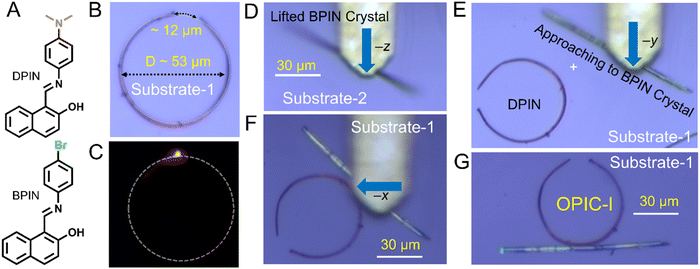 | ||
| Fig. 37 (A) Molecular structures of DPIN and BPIN. Confocal micrographs portraying AFM-based, (B and C) mechanically bent truncated circular DPIN crystal, (D) mechanical lifting, (E and F) transferring and (G) moving (with positioning) to integrate a straight BPIN crystal with a truncated circular DPIN crystal to create μ-OPIC-I. Adapted with permission from ref. 438 Copyright 2020, Wiley-VCH. | ||
6.6. Micro-organic photonic integrated circuit (μ-OPIC) components
![[1 with combining macron]](https://www.rsc.org/images/entities/char_0031_0304.gif) 1)/(01
1)/(01![[1 with combining macron]](https://www.rsc.org/images/entities/char_0031_0304.gif) ) and (0
) and (0![[1 with combining macron]](https://www.rsc.org/images/entities/char_0031_0304.gif)
![[1 with combining macron]](https://www.rsc.org/images/entities/char_0031_0304.gif) )/(011). The molecules stack along [100], forming columns. The crystal's most dominant interactions result from aromatic stacking. During mechanical crystal bending, the molecular rotation towards planarity enables compression of the inner arc (concave) in a herringbone structure. In contrast, rotation in the opposite direction facilitates elongation of the crystal's outer arc (convex).
)/(011). The molecules stack along [100], forming columns. The crystal's most dominant interactions result from aromatic stacking. During mechanical crystal bending, the molecular rotation towards planarity enables compression of the inner arc (concave) in a herringbone structure. In contrast, rotation in the opposite direction facilitates elongation of the crystal's outer arc (convex).
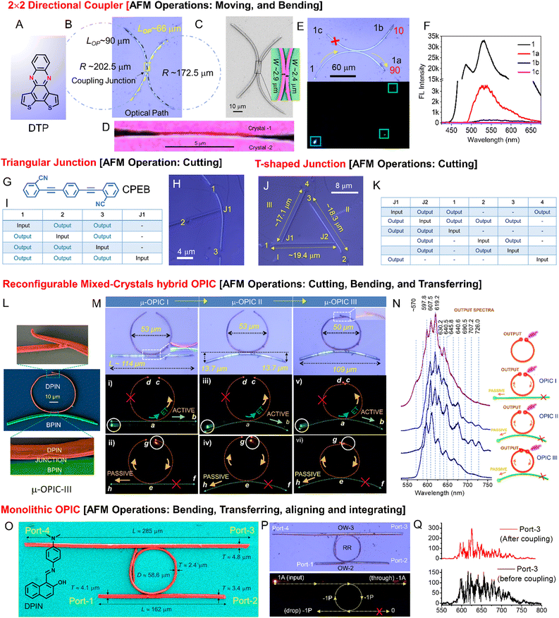 | ||
| Fig. 38 (A and G) Molecular structures of DTP, and CPEB. (B) Micromechanically fabricated two-coupled crystal waveguides (2 × 2 directional coupler) showing optical path length (LOP) between two coupled waveguides and (D) close-up view of the junction. (C) FESEM image of a directional coupler. (E) Confocal optical microscopy and fluorescence images of two coupled crystalline waveguides acting as a directional coupler when excited at one of the four termini and (F) fluorescence spectra. Confocal optical micrographs of (H) T-shaped and (J) triangular junction along with tables (I and K) summarizing input-position-dependent outputs. (L) FESEM image of μ-OPIC III. (M) Confocal optical and fluorescence images of reconfigurable μ-OPICs depicting excitation-position-dependent, directional-specific and mechanism-selective optical outputs. (N) Modulation of the optical modes at output g, due to geometrical reconfiguration of the circuit. (O) False-colored FESEM image of a monolithic micro-add-on/drop filter fabricated using DPIN microcrystals. (P) Optical and fluorescence images of the filter. (Q) Optical modes (fluorescence background-subtracted spectra) recorded at P-3 before and after coupling of OW3 with the circuit. Adapted with permissions from ref. 378 Copyright 2020, Wiley-VCH, ref. 438 Copyright 2020, Wiley-VCH, ref. 383 Copyright 2020, Wiley-VCH, ref. 444 Copyright 2021, Wiley-VCH. | ||
To fabricate a 2 × 2 directional coupler with four termini, two straight DTP crystals (crystal-1 and crystal-2) were bent into arc-shapes using AFM cantilever tip force. The microcrystal's apparent pseudoplasticity suggests that the crystal–substrate adhesive force is higher than the force that drives the recovery of the crystal shape. The radius (R) of curvature/width of two-coupled crystal-1 and crystal-2 waveguides is 202.5/2.9 and 172.5/2.4 μm, respectively (Fig. 38B–D). The curved junction facilitates light entry from one waveguide to another via an evanescent field coupling in the tapered region. Optical excitation of one of the terminals (left) of crystal-1 (Fig. 38E, see input-1), transduces the blue fluorescence signal towards the coupling junction which evanescently couples it with crystal-2. At the junction, the fluorescence signal (after reabsorption) splits into two and outcouples as green fluorescence at termini-1a and -1b in ratio 90![[thin space (1/6-em)]](https://www.rsc.org/images/entities/char_2009.gif) :
:![[thin space (1/6-em)]](https://www.rsc.org/images/entities/char_2009.gif) 10. No fluorescence signal was identified at terminal 1c, confirming the circuit's directional coupling nature. Likewise, excitation of terminals 2, 3 and 4 also shows outputs only at the opposite crystal termini. The output signal ratio also varies inversely with the optical path length (LOP ≈ 90 and 66 μm).
10. No fluorescence signal was identified at terminal 1c, confirming the circuit's directional coupling nature. Likewise, excitation of terminals 2, 3 and 4 also shows outputs only at the opposite crystal termini. The output signal ratio also varies inversely with the optical path length (LOP ≈ 90 and 66 μm).
When the input light (excitation) was applied at the right terminal of the BPIN crystal, the green fluorescence actively propagated to its opposite terminal b (Fig. 38M, i, iii and v). During fluorescence propagation, part of it evanescently coupled to the DPIN crystal and partly excited it via energy transfer. The generated orange fluorescence (active) along with green fluorescence (passive) propagated to terminal c (Fig. 38M, i, iii and v). Here, the OPICs could split the input signal into two different light signals and deliver them to the output termini b and c, but not d. Similarly, when the light input was given at DPIN terminal c, the orange fluorescence propagated in a circular path towards terminal d (Fig. 38M, ii, iv and vi). Furthermore, part of the fluorescence coupled to the BPIN crystal at the junction and was passively outcoupled at terminal h, without any output at terminal f (Fig. 38M, ii, iv and vi). As expected, the fluorescence spectra of OPICs recorded at terminal g of the BPIN (input at terminal c) reveal modulation of the optical modes (Fig. 38N). This modulation demonstrates that the variation of OPIC geometries affects the light electric-field distribution.
7. Crystals as actuators
7.1. Overview of crystal actuation
Mechanically responsive materials that can move macroscopically by application of external stimuli, such as light, heat, electricity, and chemical reactions have been studied extensively in materials chemistry over the past two decades. Such mechanically responsive materials have the potential for applications in sensors, switches, actuators, and soft robotics.104 Although research on mechanically responsive molecular crystals spans only about a decade, many mechanical crystals displaying bending,220 twisting,249 rotation,109 jumping,60 and locomotion106 have been reported. However, devices incorporating these crystals have not yet been realized. In contrast, the much more extensive research on mechanical polymers has led to the development of artificial muscles445 and soft actuators.446 Most mechanical crystals developed to date are based on photoisomerizations (including reversible photochemical reactions) or phase transitions. However, the number of crystals that undergo photoisomerization is limited. High speed is required for practical applications, but the photoisomerization actuation speed is relatively slow, in the range of seconds to minutes. Furthermore, only thin crystals of 20 μm or less can bend via a photoisomerization mechanism. Most of the crystals actuate with ultraviolet (UV) light; only a few actuate with visible or infrared light. In addition, crystals that undergo thermal phase transitions are less common than crystals that undergo photoisomerization. At present, it remains challenging to identify new phase transition crystals; these can only be found serendipitously, or by searching the literature.Thick crystals that bent quickly upon irradiation with UV or visible light due to the photothermal effect were reported recently.447 In the past, although numerous photothermally driven actuators of liquid crystal polymers have been reported,448,449 not much attention has been paid to crystal actuation by photothermal effects. The photothermal effect is a phenomenon by which thermal energy (heat) is generated by nonradiative deactivation of the photoexcited state during a photophysical process. Most of the crystals that absorb light display their own photothermal effects, which suggests that almost any crystal could be actuated by this mechanism. In this section, mechanical crystals that have been used as actuators over the past decade are reviewed. These are based on photoisomerizations, phase transitions, and photothermal effects.
7.2. Actuation by photoisomerization
Dynamic crystals altered by photoisomerization are largely restricted to typical photochromic crystals, such as diarylethenes, azobenzenes, salicylideneanilines, and anthracenes. In this section, we summarize the photomechanical actuation of crystals of azobenzenes, salicylideneanilines, fulgides, and other compounds. The photomechanical effects of diarylethene and anthracene crystals are presented in the other sections.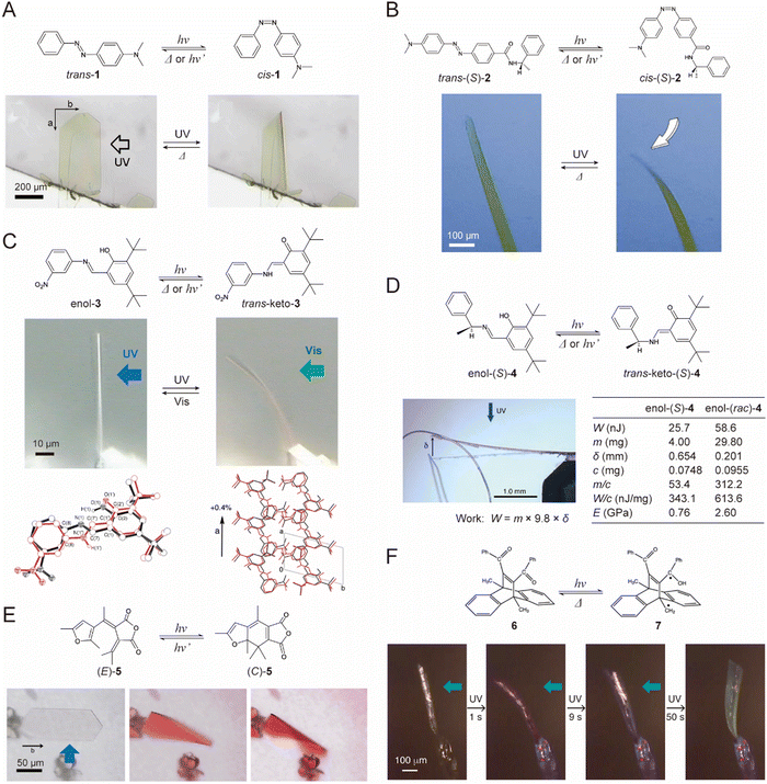 | ||
| Fig. 39 Photomechanical motions of the crystals driven by photoisomerization that occurs upon UV light irradiation. (A) Bending of a plate-like crystal of azobenzene trans-1 by trans–cis photoisomerization.179 Adapted with permission from ref. 179 Copyright 2009, American Chemical Society. (B) Bending with a twist of a plate-like crystal of chiral azobenzene trans-2.181 Adapted with permission from ref. 181 Copyright 2016, Wiley-VCH. (C) Bending and photoinduced change in the crystal structure of a plate-like crystal of salicylideneaniline enol-3 by enol–keto photoisomerization.268 Adapted with permission from ref. 268 Copyright 2011, The Royal Society of Chemistry. (D) Photomechanical lifting work of a crystal cantilever of enol-(S)-4 by enol–keto photoisomerization.452 Adapted with permission from ref. 452 Copyright 2013, American Chemical Society. (E) Curling of a thin hexagonal crystal of furylfulgide (E)-5 by photo-electrocyclization.223 Adapted with permission from ref. 223 Copyright 2012, The Chemical Society of Japan. (F) Two-step bending of a plate-like crystal of dibenzobarrelene 6.458 Adapted with permission from ref. 458 Copyright 2018, The Royal Society of Chemistry. | ||
Solid-state photoreactivity in chiral crystals usually differs from that in achiral crystals because the motion of molecules is restricted in the crystal lattice, and the chiral environment is retained during reactions.451 The photomechanics and physical properties of chiral crystals of the S-enantiomer of a salicylideneamine derivative in the enol form (enol-(S)-4) were compared to those of achiral crystals (enol-(rac)-4) composed of a racemic mixture of S- and R-enantiomers (Fig. 39D).452 Both the chiral and achiral crystals bent reversibly toward the light source under UV light irradiation due to contraction along the long crystal direction by photoisomerization. The measured Young's modulus of enol-(S)-4 was 0.8 GPa, which is smaller than the modulus of enol-(rac)-4 (2.6 GPa). Under UV light irradiation, the crystal cantilevers lifted metal rings that were 50 and 300 times heavier than the cantilevers themselves for chiral and achiral crystals, respectively, which demonstrated that the achiral enol-(rac)-4 crystal was better than the chiral enol-(S)-4 crystal as a photomechanical material.
7.3. Actuation by phase transitions
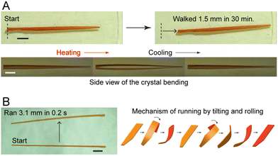 | ||
| Fig. 40 Locomotion of crystals of chiral azobenzene trans-(S)-2. (A) Inchworm-like walking of a long plate-like crystal with a thickness gradient under repeated heating and cooling cycles. (B) Fast rolling locomotion and the mechanism of a long, thin plate-like crystal with a width gradient under only one process of heating or cooling. The scale bars in (A and B) are 1 mm.106 Adapted with permission from ref. 106 Copyright 2018, Springer Nature. | ||
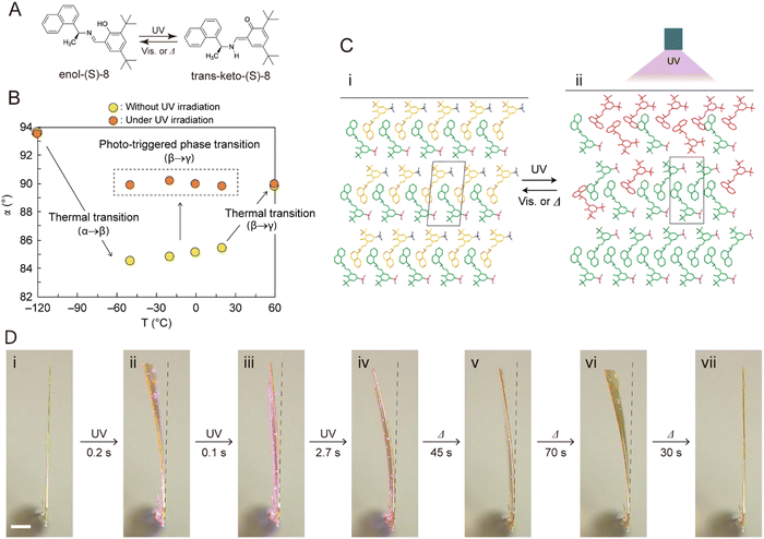 | ||
| Fig. 41 (A) Enol–keto photoisomerization of a chiral salicylideneamine, (S)-8. (B) Phototriggered phase transition based on the change of angle α. (C) Mechanism of the phototriggered phase transition. (D) Stepwise bending of a thin plate-like crystal of enol-(S)-8 upon UV irradiation. Scale bar, 500 μm.462 Adapted with permission from ref. 462 Copyright 2019, Springer Nature. | ||
7.4. Actuation by photothermal effects
A thick (240 μm) plate-like crystal of a salicylideneaniline derivative having a p-benzoyl substituent in the enol form (enol-9) bent quickly and reversibly due to a photothermal effect upon UV light irradiation (Fig. 42A and B).447 In contrast, a thin (5 μm) crystal did not exhibit significant bending, likely due to a very low degree of enol–keto photoisomerization. The photothermally driven bending, which occurred even during exposure to visible light, is caused by a temperature gradient in the thickness direction arising due to the heat conduction of photothermal energy generated near the crystal surface (Fig. 42C). High-frequency bending actuation (25 Hz) was achieved using pulsed UV irradiation (Fig. 42D). The photothermal effect is a phenomenon by which thermal energy (heat) is generated very quickly (picoseconds) by nonradiative deactivation of a photoexcited state of a photophysical process. Most crystals that absorb light display their own photothermal effects. Actuation of most crystals via a photothermal effect is conceivable; such actuation cannot be realized by photoisomerization or phase transition. The versatility and potential of crystals as actuation materials will certainly increase in the near future.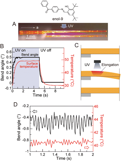 | ||
| Fig. 42 Fast bending of a crystal of enol-9 by the photothermal effect. (A) Thick plate-like crystal viewed from the side under UV irradiation. (B) Time dependence of the bending angle and the irradiated surface temperature. (C) Schematic diagram of the possible mechanism of crystal bending caused by the photothermal effect. (D) High-frequency photothermally driven bending (25 Hz) of the crystal by pulsed UV laser irradiation.447 Adapted with permission from ref. 447 Copyright 2020, The Royal Society of Chemistry. | ||
7.5. Outlook
Crystal actuation has been accomplished based on photoisomerization, phase transitions, and photothermal effects. It is important to develop and discover new principles (mechanisms) of crystal actuation. An essential requirement for the dynamic crystals is reversibility, which enables repeated actuation; crystals that irreversibly actuate by external stimuli during only one cycle are of little use. The number of crystals that undergo photoisomerization and phase transitions is limited, which is a significant disadvantage for the development of novel actuators. In contrast, most crystals that absorb light exhibit their own photothermal effects. Hence, the photothermal effect has great potential for crystal actuation, however, the crystal deformations are too small (typically, less than 1°) for practical applications.Molecular crystals, having regular, three-dimensional structures, can actuate faster, and with greater output force than polymers. Sensors, switches, actuators, and soft robots are some of the promising applications for mechanical crystals that can be moved autonomously by external stimuli. However, it may be impractical or difficult to apply a single crystal as an actuator for soft robotics. Hybridization of single crystals with polymers provides an opportunity to create actuators with more realistic movements. Indeed, light-driven crystal–polymer hybrid actuators, in which photomechanical crystals are aligned in polymer films by application of a magnetic field or rubbing, bent reversibly under photoirradiation and demonstrate the advantages of combining molecular crystals (fast response time) and polymers (large size).464,465 Extensive basic research on mechanical polymers has already led to the development of artificial muscles and soft actuators.104 Although current research on mechanical crystals is mostly limited to fundamental studies, future practical application in sensors, switches, actuators, and soft robots is envisioned.
8. Mechanical properties of molecular crystals for pharmaceutical applications
8.1. Relevance to pharmaceutical manufacturing
Molecular crystals are ubiquitous in the manufacturing of pharmaceutical products of small-molecule active pharmaceutical ingredients (APIs) since crystallization is a major means for isolating and purifying APIs. Because of their higher physical and chemical stability, the crystalline solids are still preferred before the final dosage form is manufactured even for drugs given to patients as a liquid or amorphous solid. As such, the mechanical properties of pharmaceutical crystals have a critical role in the manufacturing of most drugs. This is important to recognize as the mechanical properties of molecular crystals can vary over a wide range (Fig. 43).27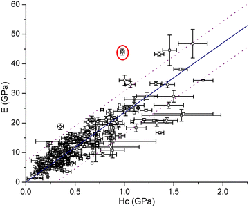 | ||
| Fig. 43 Elastic modulus (E) and indentation hardness (Hc) of molecular crystals vary over a wide range. Adapted from ref. 27. Copyright 2020, The Royal Society of Chemistry. | ||
8.2. Importance of size reduction by milling
API crystals often need to be milled to reduce the size and achieve more uniform distribution in drug products, especially for potent APIs that are delivered at low doses.466,467 Efficient delivery of APIs to the deep lung by inhalation requires particles with aerodynamic diameters less than 5 μm.468 For parenteral delivery, API crystals need to be sufficiently small to avoid ischemia.469 The dissolution rates of smaller API crystals are higher because of their larger surface area.470 For poorly soluble APIs, which account for approximately 40% of the marketed drugs and 80% of the new chemical entities in the development pipeline,471,472 the nanosized API crystals have the added advantage of enhanced solubility.473For a fixed milling process, the size distribution of the resulting powder depends on the mechanical properties, including yield strength (Y), hardness (H), Young's modulus (E), and fracture toughness (KIC) or fracture energy (R), as they affect the breakage by influencing the formation and propagation of cracks in crystals.474–478 In fact, sufficiently small particles undergo plastic deformation instead of brittle fracture when they are subjected to mechanical impact. The critical size corresponding to the plastic yielding–brittle fracture transition, dcrit, can be calculated using eqn (12) from E, Y, and R of the crystals.477
 | (12) |
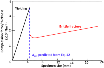 | ||
| Fig. 44 Normalized force required to cause the brittle fracture of a large particle (red line) or yield of a small particle (black line) of polystyrene. The vertical dashed line signifies the value of dcrit predicted from eqn (12). Adapted with permission from ref. 477 Copyright 1978, Nature Publishing Group. | ||
This is supported by the common observation that size reduction by milling tends to be inefficient for a highly plastic API crystal, because of the large dcrit, corresponding to a low Y. A brittleness index, defined as the ratio of H to KIC, has been used to predict the milling performance of pharmaceutical crystals.479,480 As expected, the fracture of anisotropic molecular crystals during milling is also anisotropic because cracks can propagate more easily along the weaker cleavage planes.475,481 It should be mentioned that, along with the size reduction, milling can potentially cause a loss of crystallinity or polymorph change. Thus, milled API powders need to be carefully characterized for possible phase change, and milling parameters should be optimized to minimize or even eliminate phase changes. This is important for avoiding unexpected changes in stability and dissolution performance of the API.482,483 In this regard, harder API crystals tend to be more resistant to the generation of structural disorders.484
8.3. Importance for tableting
Mechanical properties also have a major role in the success or failure of the pharmaceutical tableting process by affecting the transmission of stress through the powder bed (Fig. 45A)485 and deformation of crystals during die compaction (Fig. 45B).486 A powder consisting of more plastic crystals transmits axial compaction stresses in the radial direction (die wall stress) more effectively during loading but the residual die wall stress is usually lower.487 This explains why tablets of softer materials can be more easily ejected out of the die after compression. | ||
| Fig. 45 (A) Transmission of an axial stress (σa) to the radial die wall (σr) during die compression of a powder, creating a pseudohydrostatic stress environment and (B) effects of particle mechanical properties on bonding area formation during a powder compression cycle. More plastic particles can undergo more permanent plastic deformation than less plastic particles. Pure elastic deformation does not contribute to bonding area. Adapted with permission from ref. 485 and 507 Copyright 2009, 2022, Elsevier. | ||
According to the bonding area and bonding strength interplay model, the mechanical strength of a compressed tablet positively correlates with the total inter-particulate bonding area in the tablet.488,489 Under a given set of compression conditions, the bonding area is determined from mechanical properties, where permanent plastic deformation and fragmentation contribute to the development of the bonding area, while reversible elastic deformation does not (Fig. 45B).486,489 Therefore, the poor tableting performance of an API is generally caused by the fracture and elastic deformation being energetically preferred over crystal slip (plasticity). This problem can be effectively overcome by engineering crystals to access the API crystalline forms with higher plasticity for use in tablet formulation.490–493 It is useful to point out that, while elastic deformation is detrimental to tableting performance, 1D or 2D elastically bending molecular crystals should not be rejected on the grounds of expected poor tabletability. This is because the one-dimensional stress applied to bend a crystal is fundamentally different from the pseudohydrostatic stress during die compression. Plastic deformation of crystals, through a slip among crystallographic planes, along even one direction, is sufficient for developing a large bonding area between API crystals, because of their random orientation in the powder bed.494
8.4. Importance for punch sticking
While enhancing API crystal plasticity is effective in solving the poor tabletability problem, higher plasticity also correlates with a higher tendency of punch sticking during tableting.495 When punch sticking occurs, the tableting process must be stopped as the contaminated punch causes a change in tablet weight and defective tablet surfaces. If not resolved, these issues can lead to the rejection of an entire batch.496 The higher punch sticking propensity of more plastic crystals arises from the development of a larger area of contact with the punch surface during compression, which makes it more difficult to separate the API crystals from the punch surface (Fig. 46).497 Therefore, to avoid the punch sticking problem of an API, a crystal form of the API with lower plasticity may be designed through crystal engineering to mitigate or eliminate the problem.333,498 Such an effort can be significantly facilitated by engaging available computational tools to predict crystal plasticity.333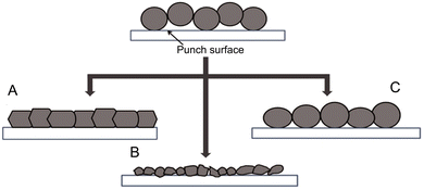 | ||
| Fig. 46 Effects of mechanical behaviors of API crystals on punch sticking propensity. (A) Plastic crystals undergo extensive deformation so that larger areas of contact with the punch surface are developed, leading to severe sticking; (B) brittle and (C) elastic API crystals only develop small areas of contact with the punch surface at the end of the compression cycle so that they can easily detach from the punch surface after compression, leading to low sticking propensity. Adapted with permission from ref. 495. Copyright 2017, Elsevier. | ||
8.5. The current status of this research field and future perspective
Temperature rises during prolonged milling or compaction because of the high energy input inherent to these processes. A temperature rise may affect the mechanical properties of an API, which can consequently cause unexpected problems during large-scale manufacturing. It has been shown that the API crystals become softer at higher temperatures.159,499 This would explain the common observation that punch sticking problems can either become aggravated over time or unexpectedly appear during large-scale tablet manufacturing.It was also shown that more plastic polymorphs of curcumin and sulfathiazole exhibit higher solubility.500 A globally positive trend between plasticity and solubility of polymorphs is reasonable because they both correlate with weaker intermolecular interactions and lower lattice energy. If broadly applicable, this relationship offers a way to rank-order the solubility of API polymorphs based on their mechanical properties. When the amount of an API is insufficient for conducting solubility experiments or when the solubility of a polymorph cannot be easily measured due to a facile phase conversion during the solubility experiment, their solubilities can still be rank ordered based on the mechanical properties attained through nanoindentation. However, a predictive model to reliably predict solubility from hardness of drug crystals must incorporate the factor of hardness anisotropy. To this end, more systems must be thoroughly investigated to provide sufficient data for developing such a model. It may also be useful to incorporate mechanical properties calculated from their crystal structures.
Similar to metallic crystals, the mechanical properties of molecular crystals can be modified by dislocations. For example, omeprazole crystals are hardened when the percentage of a tautomer in the crystals increases.501 The incorporation of molecular impurities at a low concentration initially lowers the elastic modulus of uric acid crystals by creating dislocations to promote plastic deformation through slip. However, the crystals become harder when the impurity level surpasses a specific threshold.502 This line of research deserves more attention because it may give us the ability to fine-tune mechanical properties for optimal performance in pharmaceutical manufacturing.
The mechanical responses of pharmaceutical crystals are diverse, from being highly elastic319,503–505 to highly plastic.308,506 Therefore, it is possible to effectively solve several pharmaceutical problems through the modulation of crystal mechanical properties by applying various crystal engineering approaches. Such efforts are most effective when they are based on a clear understanding of the crystal structure, mechanical properties, and performance relationship.507 However, despite the significant recent progress, a broadly applicable theoretical framework for reliably predicting mechanical properties of molecular crystals from their structures remains elusive. Therefore, continued research in this direction is strongly encouraged. The first step towards achieving this goal is to expand the list of molecular crystals for which the mechanical properties have been carefully characterized and structural origin has been understood. The analysis of a high-quality database containing a large number of crystals, aided by machine learning and other techniques, will then enable the development of a theoretical framework that can be used to accurately predict the properties and performance of interest from their crystal structures.
9. Final remarks
The deformations of solid bodies are grounded in their characteristic mechanical properties. If the center of mass or the rotational inertia of a body changes over time, deformations become translations and rotations, i.e., motion. In crystals made from molecules, the aforementioned dynamic processes can be controlled or even programmed into the component compounds but this control can only be realized once we reckon systematically with the scarcity of data on the fundamental mechanical properties of organic crystals. Our poor intuition with regard to the mechanical properties of, and mechanical effects displayed by, molecular crystals is likely a result of the compartmentalization of research communities whose common interests are only now coming into focus. The solid-state chemistry research community has traditionally emphasized X-ray crystal structure elucidation of monoliths from which correlations with solid-state reactivity and crystal growth (crystal engineering) were drawn. The broader mechanical engineering community, on the other hand, has hardly considered molecular crystals as a viable class of engineering materials, quoting their small size, pronounced softness, and proneness to wear and tear as some of their drawbacks. It is encouraging to see that the cross-talk between these two communities has been already initiated at multiple levels, and it already underpins some notable progress in understanding of molecular crystals, tying fundamental structural studies with applications in photonics, electronics, and soft robotics.The key to the understanding of the mechanical effects of crystals is the relationship between structural details such as the strength, abundance, and directionality (anisotropy) of intermolecular interactions, rigidity and conformational flexibility of molecules, material symmetries and the mechanical property profile. This particular aspect requires reliable high-throughput experimental methods that can provide data from a suite of crystal samples with varying chemical and crystal structures. The experimental techniques used to characterize mechanical effects should be complementary—structural, spectroscopic, microscopic, and thermal—to provide sufficient supporting evidence in conjunction with mechanical characterization.
As the amount of data increases, so does the necessity for systematic investigations that would establish molecular crystals in the global material property space. As in many contemporary scientific endeavors of scientific exploration, computational methods will play an increasingly important role in gaining deeper understanding of mechanical properties and effects of molecular crystals. Modeling is particularly important for the emerging dynamic properties of molecular crystals. Once reliable theoretical protocols have been established, computational methods could be used to not only explain the experimental data, but also to predict mechanical properties and even dynamic mechanical effects in molecular crystals. This latter goal would necessarily require combined simulation approaches, where phenomena that occur on very different scales—both in length and time—are tackled by atomistic classical and quantum chemical methods as well as by coarse-grained modelling. The results from such concerted research efforts, based on experimental data and supplemented by robust computational techniques, will accelerate the application of molecular crystals. In these efforts, one needs to think outside the chemistry–physics dichotomy that has entrenched science and engineering training, and be cognizant of the virtues of modes of analysis—as well as of their limitations—that each complementary community has developed in isolation.
Concurrent with these developments, there are efforts aimed to demonstrate that molecular crystals can act as simple devices that are able to move objects, progress through space, transmit light, reshape, self-heal, conduct electricity, or transmit information. These examples should go beyond mere replication of engineering devices analogous to those that are available with other materials; they should instead capitalize on the true assets of molecular crystals being anisotropic, light, ordered materials and provide realistic quantifiable parameters to assess their performance.
Couplings between the molecular-scale changes that occur under the effect of external stimuli and their translation and amplification to macroscopic scales are multifaceted phenomena. Researchers thus resort to either the ‘molecular approach’ or to the general mechanical theory, which in most cases suffices to explain simple observations and to make correlations with physical data. Going beyond those semiempirical and increasingly quantitative approaches, however, requires concerted efforts from researchers working on various aspects of mechanical properties and effects of molecular crystals, as is the exemplary case of this review article which combines contributions from various experts. Such collaborative efforts will likely enhance the understanding of the underlying phenomena, provide realistic performance parameters for assessment of various assets of molecular crystals, and will eventually facilitate the translation of these exciting materials from the crystallographic laboratory to the prototyping stage and finally to real-world implementations and applications.
Molecular crystals, typically monocomponent, uniform structures, are not obviously like multicomponent hierarchical machines whether evolved as in biology or constructed in the machine lab. Nevertheless, they embody sufficient complexity that they can sometimes mimic the functions of those objects designed to be animated. Once we learn to ‘pull the levers’ of molecular crystalline machines with greater fidelity through the cooperative studies outlined here, the greater will be the mimicry that emerges in the near future.
Author contributions
Conceptualization, P. N.; data curation, W. M. A., D. W. D., D. K., J. M. H., M. B. A.-H., I. T., F. T., G. C.-A., A. G. S., T. A., Y. H., M. A., L. L., S. H., D. P. K., S. M., H. K., S. K., Y. D., R. C., H. Z., C. C. S., C. B., R. O. A., B. K., and P. N.; funding acquisition, P. N.; project administration, W. M. A., J. M. H., M. B. A.-H., I. T., and P. N.; resources, P. N.; supervision, P. N.; writing – original draft, W. M. A., J. M. H., M. B. A.-H., I. T., and P. N. (abstract, Sections 1.1., 1.2., 3.1, and final remarks); D. P. K. retrieved and compiled the information used to prepare Fig. 1.; M. B. A.-H. prepared the graphics; I. T. and D. P. K. consolidated the reference list and citations based on the contributions from all the authors; A. S. G., and B. K. (Sections 2.1, 2.2, 2.3, 2.4, and 2.5); S. K., D. K., F. T. R. O. A., and C. B. (Sections 3.2, 3.3, 3.4 and 3.5); T. A., M. A., and S. M. (Sections 4.1, 4.2, 4.3, 4.4 and 4.5); D. W. D., G. C.-A., and Y. D. (Sections 5.1, 5.2 and 5.3); L. L., and H. Z. (Sections 6.1, 6.2 and 6.3); R. C. (Sections 6.4, 6.5, and 6.6); Y. H., S. H., and H. K. (Sections 7.1, 7.2, 7.3, 7.4 and 7.5); C. C. S. (Sections 8.1 and 8.2); and writing, review, compilation and editing, W. M. A., and P. N.Conflicts of interest
The authors declare there is no financial or other conflict of interest.Acknowledgements
P. N. thanks New York University Abu Dhabi for the financial support of the research performed in the Smart Materials Lab over the past ten years (2012–2022). This material is based upon works supported by Tamkeen under NYUAD RRC Grant No. CG011 (Center for Smart Engineering Materials).References
- R. O. Ritchie, Nat. Mater., 2011, 10, 817–822 CrossRef CAS PubMed
.
- S. Varughese, M. S. R. N. Kiran, U. Ramamurty and G. R. Desiraju, Angew. Chem., Int. Ed., 2013, 52, 2701–2712 CrossRef CAS PubMed
.
- A. Mondal, B. Bhattacharya, S. Das, S. Bhunia, R. Chowdhury, S. Dey and C. M. Reddy, Angew. Chem., Int. Ed., 2020, 59, 10971–10980 CrossRef CAS PubMed
.
- G. R. Krishna, R. Devarapalli, G. Lal and C. M. Reddy, J. Am. Chem. Soc., 2016, 138, 13561–13567 CrossRef CAS PubMed
.
- P. Commins, D. P. Karothu and P. Naumov, Angew. Chem., Int. Ed., 2019, 58, 10052–10060 CrossRef CAS PubMed
.
- P. Gupta, S. A. Rather, B. K. Saha, T. Panda, D. P. Karothu and N. K. Nath, Cryst. Growth Des., 2020, 20, 2847–2852 CrossRef CAS
.
-
J. Gilman, Chemistry and Physics of Mechanical Hardness, Wiley, 2009 Search PubMed
.
-
Functional Materials: Preparation, Processing and Applications, ed. S. Banerjee and A. K. Tyagi, Elsevier, Amsterdam, 2011 Search PubMed
.
- B. R. Lawn and D. B. Marshall, J. Am. Ceram. Soc., 1979, 62, 347–350 CrossRef CAS
.
- J. J. Vlassak and W. D. Nix, J. Mech. Phys. Solids, 1994, 42, 1223–1245 CrossRef
.
- W. Lu, Y. Shi, X. Li and Y. Lei, J. Mater. Eng. Perform., 2013, 22, 1694–1700 CrossRef CAS
.
- P. Zhang, S. X. Li and Z. F. Zhang, Mater. Sci. Eng., A, 2011, 529, 62–73 CrossRef CAS
.
- C. M. Reddy, G. R. Krishna and S. Ghosh, CrystEngComm, 2010, 12, 2296–2314 RSC
.
- W. C. Oliver and G. M. Pharr, J. Mater. Res., 2004, 19, 3–20 CrossRef CAS
.
-
N. R. Moody, W. W. Gerberich, N. Burnham and S. P. Baker, Fundamentals of Nanoindentation and Nanotribology (No. CONF-980405-), Materials Research Society, Warrendale, PA (United States), 1998 Search PubMed
.
- K. I. Schiffmann, Int. J. Mater. Res., 2007, 98, 424–429 CrossRef CAS
.
-
A. L. M. Costa, D. J. Shuman, R. R. Machado and M. S. Andrade, Determination of the Compliance of an Instrumented Indentation Testing Machine, HARDMEKO 2004, Washington DC, USA, November 2–5, 2004 Search PubMed
.
- W. C. Oliver and G. M. Pharr, J. Mater. Res., 1992, 7, 1564–1583 CrossRef CAS
.
- J. J. Vlassak, M. Ciavarella, J. R. Barber and X. Wang, J. Mech. Phys. Solids, 2003, 51, 1701–1721 CrossRef
.
- W. J. Meng and G. L. Eesley, Thin Solid Films, 1995, 271, 108–116 CrossRef CAS
.
- W. Wang and K. Lu, J. Mater. Res., 2002, 17, 2314–2320 CrossRef CAS
.
- T. Nakamura and Y. Gu, Mech. Mater., 2007, 39, 340–356 CrossRef
.
- J. G. Swadener, J. Y. Rho and G. M. Pharr, J. Biomed. Mater. Res., 2001, 57, 108–112 CrossRef CAS PubMed
.
-
R. Hill, The Mathematical Theory of Plasticity, Oxford University Press, London, 1950 Search PubMed
.
- D. Labonte, A.-K. Lenz and M. L. Oyen, Acta Biomater., 2017, 57, 373–383 CrossRef CAS PubMed
.
- M. Sakai, J. Mater. Res., 1999, 14, 3630–3639 CrossRef CAS
.
- C. Wang and C. C. Sun, CrystEngComm, 2020, 22, 1149–1153 RSC
.
-
M. F. Ashby, Materials Selection in Mechanical Design, Elsevier, 2011 Search PubMed
.
- P. Naumov, S. Chizhik, M. K. Panda, N. K. Nath and E. Boldyreva, Chem. Rev., 2015, 115, 12440–12490 CrossRef CAS PubMed
.
- P. Naumov, D. P. Karothu, E. Ahmed, L. Catalano, P. Commins, J. Mahmoud Halabi, M. B. Al-Handawi and L. Li, J. Am. Chem. Soc., 2020, 142, 13256–13272 CrossRef CAS PubMed
.
- P. Commins, I. T. Desta, D. P. Karothu, M. K. Panda and P. Naumov, Chem. Commun., 2016, 52, 13941–13954 RSC
.
- S. Saha, M. K. Mishra, C. M. Reddy and G. R. Desiraju, Acc. Chem. Res., 2018, 51, 2957–2967 CrossRef CAS PubMed
.
- E. Ahmed, D. P. Karothu and P. Naumov, Angew. Chem., Int. Ed., 2018, 57, 8837–8846 CrossRef CAS PubMed
.
- S. K. Park and Y. Diao, Chem. Soc. Rev., 2020, 49, 8287–8314 RSC
.
- S. Das, A. Mondal and C. M. Reddy, Chem. Soc. Rev., 2020, 49, 8878–8896 RSC
.
- A. Basile, M. Hilder, F. Makhlooghiazad, C. Pozo-Gonzalo, D. R. MacFarlane, P. C. Howlett and M. Forsyth, Adv. Energy Mater., 2018, 8, 1703491 CrossRef
.
- N. K. Nath, M. K. Panda, S. C. Sahoo and P. Naumov, CrystEngComm, 2014, 16, 1850–1858 RSC
.
- A. G. Shtukenberg, Y. O. Punin, A. Gujral and B. Kahr, Angew. Chem., Int. Ed., 2014, 53, 672–699 CrossRef CAS PubMed
.
- O. Sato, Nat. Chem., 2016, 8, 644–656 CrossRef CAS
.
- D. Kitagawa, T. Okuyama, R. Tanaka and S. Kobatake, Chem. Mater., 2016, 28, 4889–4892 CrossRef CAS
.
- A. Ravi and K. M. Sureshan, Angew. Chem., Int. Ed., 2018, 57, 9362–9366 CrossRef CAS PubMed
.
- G. A. R. Nobes, R. H. Marchessault, H. Chanzy, B. H. Briese and D. Jendrossek, Macromolecules, 1996, 29, 8330–8333 CrossRef CAS
.
- M. K. Mishra, A. Mukherjee, U. Ramamurty and G. R. Desiraju, IUCrJ, 2015, 2, 653–660 CrossRef CAS PubMed
.
- T. Seki, T. Mashimo and H. Ito, Chem. Sci., 2019, 10, 4185–4191 RSC
.
- M. K. Panda, S. Ghosh, N. Yasuda, T. Moriwaki, G. D. Mukherjee, C. M. Reddy and P. Naumov, Nat. Chem., 2015, 7, 65–72 CrossRef CAS PubMed
.
- F. Tong, M. Al-Haidar, L. Zhu, R. O. Al-Kaysi and C. J. Bardeen, Chem. Commun., 2019, 55, 3709–3712 RSC
.
- O. S. Bushuyev, A. Tomberg, T. Friščić and C. J. Barrett, J. Am. Chem. Soc., 2013, 135, 12556–12559 CrossRef CAS PubMed
.
- S. Saha and G. R. Desiraju, Chem. Commun., 2017, 53, 6371–6374 RSC
.
- T. Kim, M. K. Al-Muhanna, S. D. Al-Suwaidan, R. O. Al-Kaysi and C. J. Bardeen, Angew. Chem., Int. Ed., 2013, 52, 6889–6893 CrossRef CAS PubMed
.
- H. Chung, D. Dudenko, F. Zhang, G. D’Avino, C. Ruzié, A. Richard, G. Schweicher, J. Cornil, D. Beljonne, Y. Geerts and Y. Diao, Nat. Commun., 2018, 9, 278 CrossRef PubMed
.
- T. Sasaki, S. Sakamoto and S. Takamizawa, Cryst. Growth Des., 2019, 19, 5491–5493 CrossRef CAS
.
- S. Takamizawa, Y. Takasaki, T. Sasaki and N. Ozaki, Nat. Commun., 2018, 9, 3984 CrossRef PubMed
.
- T. Sasaki and S. Takamizawa, Cryst. Growth Des., 2020, 20, 6990–6994 CrossRef CAS
.
- S. Takamizawa and Y. Takasaki, Cryst. Growth Des., 2019, 19, 1912–1920 CrossRef CAS
.
- M. C. Etter and A. R. Siedle, J. Am. Chem. Soc., 1983, 105, 641–643 CrossRef CAS
.
- M. K. Panda, R. Centore, M. Causà, A. Tuzi, F. Borbone and P. Naumov, Sci. Rep., 2016, 6, 29610 CrossRef CAS PubMed
.
- M. Lusi and J. Bernstein, Chem. Commun., 2013, 49, 9293–9295 RSC
.
- D. P. Karothu and P. Naumov, Isr. J. Chem., 2021, 61, 557–562 CrossRef CAS
.
- M. I. Tamboli, D. P. Karothu, M. S. Shashidhar, R. G. Gonnade and P. Naumov, Chem. – Eur. J., 2018, 24, 4133–4139 CrossRef CAS PubMed
.
- P. Naumov, S. C. Sahoo, B. A. Zakharov and E. V. Boldyreva, Angew. Chem., Int. Ed., 2013, 52, 9990–9995 CrossRef CAS PubMed
.
- F. Tong, M. P. Hanson and C. J. Bardeen, Phys. Chem. Chem. Phys., 2016, 18, 31936–31945 RSC
.
- D. P. Karothu, J. Weston, I. T. Desta and P. Naumov, J. Am. Chem. Soc., 2016, 138, 13298–13306 CrossRef CAS PubMed
.
- K. Yadava, G. Gallo, S. Bette, C. E. Mulijanto, D. P. Karothu, I.-H. Park, R. Medishetty, P. Naumov, R. E. Dinnebier and J. J. Vittal, IUCrJ, 2020, 7, 83–89 CrossRef CAS PubMed
.
- S. Takahashi, H. Miura, H. Kasai, S. Okada, H. Oikawa and H. Nakanishi, J. Am. Chem. Soc., 2002, 124, 10944–10945 CrossRef CAS PubMed
.
- O. Bolton, L. R. Simke, P. F. Pagoria and A. J. Matzger, Cryst. Growth Des., 2012, 12, 4311–4314 CrossRef CAS
.
- K. B. Landenberger and A. J. Matzger, Cryst. Growth Des., 2010, 10, 5341–5347 CrossRef CAS
.
- G. Liu, R. Gou, H. Li and C. Zhang, Cryst. Growth Des., 2018, 18, 4174–4186 CrossRef CAS
.
- K. Numata, P. Cebe and D. L. Kaplan, Biomaterials, 2010, 31, 2926–2933 CrossRef CAS PubMed
.
- R. H. Marchessault and J. Kawada, Macromolecules, 2004, 37, 7418–7420 CrossRef CAS
.
- T. Kim, L. Zhu, L. J. Mueller and C. J. Bardeen, CrystEngComm, 2012, 14, 7792–7799 RSC
.
- K. Omoto, T. Nakae, M. Nishio, Y. Yamanoi, H. Kasai, E. Nishibori, T. Mashimo, T. Seki, H. Ito, K. Nakamura, N. Kobayashi, N. Nakayama, H. Goto and H. Nishihara, J. Am. Chem. Soc., 2020, 142, 12651–12657 CrossRef CAS PubMed
.
- S. C. Sahoo, S. B. Sinha, M. S. R. N. Kiran, U. Ramamurty, A. F. Dericioglu, C. M. Reddy and P. Naumov, J. Am. Chem. Soc., 2013, 135, 13843–13850 CrossRef CAS PubMed
.
- S. Mannepalli and K. S. R. N. Mangalampalli, Crystals, 2017, 7, 324 CrossRef
.
- S. Bhandary, A. J. Thompson, J. C. McMurtrie, J. K. Clegg, P. Ghosh, S. R. N. K. Mangalampalli, S. Takamizawa and D. Chopra, Chem. Commun., 2020, 56, 12841–12844 RSC
.
- E. Ahmed, D. P. Karothu, M. Warren and P. Naumov, Nat. Commun., 2019, 10, 3723 CrossRef PubMed
.
- Y. Zhang, C. Peng, Z. Zhou, R. Duan, H. Ji, Y. Che and J. Zhao, Adv. Mater., 2015, 27, 320–325 CrossRef CAS PubMed
.
- D. J. Shields, D. P. Karothu, K. Sambath, R. A. A. U. Ranaweera, S. Schramm, A. Duncan, B. Duncan, J. A. Krause, A. D. Gudmundsdottir and P. Naumov, J. Am. Chem. Soc., 2020, 142, 18565–18575 CrossRef CAS PubMed
.
- J. M. Cole, J. de, J. Velazquez-Garcia, D. J. Gosztola, S. G. Wang and Y.-S. Chen, Chem. Mater., 2019, 31, 4927–4935 CrossRef CAS
.
- E. Ahmed, D. P. Karothu, L. Pejov, P. Commins, Q. Hu and P. Naumov, J. Am. Chem. Soc., 2020, 142, 11219–11231 CrossRef CAS PubMed
.
- M. Annadhasan, D. P. Karothu, R. Chinnasamy, L. Catalano, E. Ahmed, S. Ghosh, P. Naumov and R. Chandrasekar, Angew. Chem., Int. Ed., 2020, 59, 13821–13830 CrossRef CAS PubMed
.
- P. Gupta, S. Allu, D. P. Karothu, T. Panda and N. K. Nath, Cryst. Growth Des., 2021, 21, 1931–1938 CrossRef CAS
.
- H. Koshima and N. Ojima, Dyes Pigm., 2012, 92, 798–801 CrossRef CAS
.
- J. Peng, K. Ye, C. Liu, J. Sun and R. Lu, J. Mater. Chem. C, 2019, 7, 5433–5441 RSC
.
- Y. Sun, Y. Lei, H. Dong, Y. Zhen and W. Hu, J. Am. Chem. Soc., 2018, 140, 6186–6189 CrossRef CAS PubMed
.
- A. Worthy, A. Grosjean, M. C. Pfrunder, Y. Xu, C. Yan, G. Edwards, J. K. Clegg and J. C. McMurtrie, Nat. Chem., 2018, 10, 65–69 CrossRef CAS PubMed
.
-
F. Bernauer, “Gedrillte” Kristalle; Verbreitung, Entstehungsweise und Beziehungen zu optischer Aktivität und Molekülasymmetrie, Gebrüder Borntraeger, Berlin, 1929 Search PubMed
.
- S. Saha and G. R. Desiraju, J. Am. Chem. Soc., 2017, 139, 1975–1983 CrossRef CAS PubMed
.
- G. Campillo-Alvarado, C. Li, Z. Feng, K. M. Hutchins, D. C. Swenson, H. Höpfl, H. Morales-Rojas and L. R. MacGillivray, Organometallics, 2020, 39, 2197–2201 CrossRef CAS
.
- L. Zhu, R. O. Al-Kaysi and C. J. Bardeen, J. Am. Chem. Soc., 2011, 133, 12569–12575 CrossRef CAS PubMed
.
- R. Rai, B. P. Krishnan and K. M. Sureshan, Proc. Natl. Acad. Sci. U. S. A., 2018, 115, 2896–2901 CrossRef CAS PubMed
.
- P. Gupta, D. P. Karothu, E. Ahmed, P. Naumov and N. K. Nath, Angew. Chem., Int. Ed., 2018, 57, 8498–8502 CrossRef CAS PubMed
.
- P. Commins, M. B. Al-Handawi, D. P. Karothu, G. Raj and P. Naumov, Chem.
Sci., 2020, 11, 2606–2613 RSC
.
- S. Hayashi and T. Koizumi, Angew. Chem., 2016, 128, 2751–2754 CrossRef
.
- R. O. Al-Kaysi, L. Zhu, M. Al-Haidar, M. K. Al-Muhannah, K. El-Boubbou, T. M. Hamdan and C. J. Bardeen, CrystEngComm, 2015, 17, 8835–8842 RSC
.
- L. Li, P. Commins, M. B. Al-Handawi, D. P. Karothu, J. M. Halabi, S. Schramm, J. Weston, R. Rezgui and P. Naumov, Chem. Sci., 2019, 10, 7327–7332 RSC
.
- A. Colin-Molina, D. P. Karothu, M. J. Jellen, R. A. Toscano, M. A. Garcia-Garibay, P. Naumov and B. Rodríguez-Molina, Matter, 2019, 1, 1033–1046 CrossRef
.
- S. K. Park, H. Sun, H. Chung, B. B. Patel, F. Zhang, D. W. Davies, T. J. Woods, K. Zhao and Y. Diao, Angew. Chem., Int. Ed., 2020, 59, 13004–13012 CrossRef CAS PubMed
.
- I. Ohkata and K. Otsuka, J. Robot. Soc. Jpn., 1995, 13, 189–192 CrossRef
.
- S. Takamizawa and Y. Miyamoto, Angew. Chem., Int. Ed., 2014, 53, 6970–6973 CrossRef CAS PubMed
.
- S. Takamizawa and Y. Takasaki, Angew. Chem., Int. Ed., 2015, 54, 4815–4817 CrossRef CAS PubMed
.
- T. Mutai, T. Sasaki, S. Sakamoto, I. Yoshikawa, H. Houjou and S. Takamizawa, Nat. Commun., 2020, 11, 1824 CrossRef CAS PubMed
.
- T. Sasaki, S. Sakamoto, Y. Takasaki and S. Takamizawa, Angew. Chem., Int. Ed., 2020, 59, 4340–4343 CrossRef CAS PubMed
.
- S. Takamizawa and Y. Takasaki, Chem. Sci., 2016, 7, 1527–1534 RSC
.
-
H. Koshima, Mechanically Responsive Materials for Soft Robotics, Wiley-VCH Verlag, Weinheim, Germany, 2020 Search PubMed
.
- H. Wang, P. Chen, Z. Wu, J. Zhao, J. Sun and R. Lu, Angew. Chem., Int. Ed., 2017, 56, 9463–9467 CrossRef CAS PubMed
.
- T. Taniguchi, H. Sugiyama, H. Uekusa, M. Shiro, T. Asahi and H. Koshima, Nat. Commun., 2018, 9, 538 CrossRef PubMed
.
- Y. Norikane, S. Tanaka and E. Uchida, CrystEngComm, 2016, 18, 7225–7228 RSC
.
- E. Uchida, R. Azumi and Y. Norikane, Nat. Commun., 2015, 6, 7310 CrossRef CAS PubMed
.
- L. Zhu, R. O. Al-Kaysi and C. J. Bardeen, Angew. Chem., Int. Ed., 2016, 55, 7073–7076 CrossRef CAS PubMed
.
- B. Kahr and A. G. Shtukenberg, Isr. J. Chem., 2017, 57, 31–38 CrossRef CAS
.
- A. Shtukenberg, E. Gunn, M. Gazzano, J. Freudenthal, E. Camp, R. Sours, E. Rosseeva and B. Kahr, ChemPhysChem, 2011, 12, 1558–1571 CrossRef CAS PubMed
.
- A. G. Shtukenberg, X. Zhu, Y. Yang and B. Kahr, Cryst. Growth Des., 2020, 20, 6186–6197 CrossRef CAS
.
- B. Kahr, M. Tan, H.-M. Ye and A. G. Shtukenberg, Cryst. Growth Des., 2019, 19, 5999–6003 CrossRef CAS
.
- Y. Yang, Y. Zhang, C. T. Hu, M. Sun, S. Jeong, S. S. Lee, A. G. Shtukenberg and B. Kahr, Chem. Mater., 2022, 34, 1778–1788 CrossRef CAS
.
- A. G. Shtukenberg, M. Tan, L. Vogt-Maranto, E. J. Chan, W. Xu, J. Yang, M. E. Tuckerman, C. T. Hu and B. Kahr, Cryst. Growth Des., 2019, 19, 4070–4080 CrossRef CAS
.
- J. Yang, C. T. Hu, X. Zhu, Q. Zhu, M. D. Ward and B. Kahr, Angew. Chem., Int. Ed., 2017, 56, 10165–10169 CrossRef CAS PubMed
.
- A. G. Shtukenberg, Q. Zhu, D. J. Carter, L. Vogt, J. Hoja, E. Schneider, H. Song, B. Pokroy, I. Polishchuk, A. Tkatchenko, A. R. Oganov, A. L. Rohl, M. E. Tuckerman and B. Kahr, Chem. Sci., 2017, 8, 4926–4940 RSC
.
- M. Tan, A. G. Shtukenberg, S. Zhu, W. Xu, E. Dooryhee, S. M. Nichols, M. D. Ward, B. Kahr and Q. Zhu, Faraday Discuss., 2018, 211, 477–491 RSC
.
- X. Cui, A. L. Rohl, A. Shtukenberg and B. Kahr, J. Am. Chem. Soc., 2013, 135, 3395–3398 CrossRef CAS PubMed
.
- A. G. Shtukenberg, R. Drori, E. V. Sturm, N. Vidavsky, A. Haddad, J. Zheng, L. A. Estroff, H. Weissman, S. G. Wolf, E. Shimoni, C. Li, N. Fellah, E. Efrati and B. Kahr, Angew. Chem., 2020, 132, 14701–14709 CrossRef
.
- A. G. Shtukenberg, A. Gujral, E. Rosseeva, X. Cui and B. Kahr, CrystEngComm, 2015, 17, 8817–8824 RSC
.
- A. G. Shtukenberg, Y. O. Punin, E. Gunn and B. Kahr, Chem. Rev., 2012, 112, 1805–1838 CrossRef CAS PubMed
.
- B. Kahr, J. Freudenthal and E. Gunn, Acc. Chem. Res., 2010, 43, 684–692 CrossRef CAS PubMed
.
- O. Arteaga and B. Kahr, J. Opt. Soc. Am. B, 2019, 36, F72–F83 CrossRef CAS
.
- E. Gunn, R. Sours, J. B. Benedict and B. Kahr, J. Am. Chem. Soc., 2006, 128, 14234–14235 CrossRef CAS PubMed
.
- X. Cui, A. G. Shtukenberg, J. Freudenthal, S. Nichols and B. Kahr, J. Am. Chem. Soc., 2014, 136, 5481–5490 CrossRef CAS PubMed
.
- X. Cui, S. M. Nichols, O. Arteaga, J. Freudenthal, F. Paula, A. G. Shtukenberg and B. Kahr, J. Am. Chem. Soc., 2016, 138, 12211–12218 CrossRef CAS PubMed
.
- J. H. Freudenthal, E. Hollis and B. Kahr, Chirality, 2009, 21, E20–E27 CrossRef CAS PubMed
.
- H.-M. Ye, J. Xu, J. Freudenthal and B. Kahr, J. Am. Chem. Soc., 2011, 133, 13848–13851 CrossRef CAS PubMed
.
- M. Tan, W. Jiang, A. T. Martin, A. G. Shtukenberg, M. D. McKee and B. Kahr, Chem. Commun., 2020, 56, 7353–7356 RSC
.
- H.-M. Ye, J. H. Freudenthal, M. Tan, J. Yang and B. Kahr, Macromolecules, 2019, 52, 8514–8520 CrossRef CAS
.
- A. G. Shtukenberg, X. Cui, J. Freudenthal, E. Gunn, E. Camp and B. Kahr, J. Am. Chem. Soc., 2012, 134, 6354–6364 CrossRef CAS PubMed
.
- B. Kahr, A. Shtukenberg, E. Gunn, D. J. Carter and A. L. Rohl, Cryst. Growth Des., 2011, 11, 2070–2073 CrossRef CAS
.
- A. G. Shtukenberg, J. Freudenthal and B. Kahr, J. Am. Chem. Soc., 2010, 132, 9341–9349 CrossRef CAS PubMed
.
- M. Rosenthal, M. Burghammer, G. Bar, E. T. Samulski and D. A. Ivanov, Macromolecules, 2014, 47, 8295–8304 CrossRef CAS
.
- E. Efrati and W. T. M. Irvine, Phys. Rev. X, 2014, 4, 011003 Search PubMed
.
- Q. Zhu, A. G. Shtukenberg, D. J. Carter, T.-Q. Yu, J. Yang, M. Chen, P. Raiteri, A. R. Oganov, B. Pokroy, I. Polishchuk, P. J. Bygrave, G. M. Day, A. L. Rohl, M. E. Tuckerman and B. Kahr, J. Am. Chem. Soc., 2016, 138, 4881–4889 CrossRef CAS PubMed
.
- J. Yang, C. T. Hu, A. G. Shtukenberg, Q. Yin and B. Kahr, CrystEngComm, 2018, 20, 1383–1389 RSC
.
- A. Shtukenberg, J. Freundenthal, E. Gunn, L. Yu and B. Kahr, Cryst. Growth Des., 2011, 11, 4458–4462 CrossRef CAS
.
- J. M. Schultz, Polymer, 2003, 44, 433–441 CrossRef CAS
.
- B. Crist and J. M. Schultz, Prog. Polym. Sci., 2016, 56, 1–63 CrossRef CAS
.
- A. Toda, M. Okamura, K. Taguchi, M. Hikosaka and H. Kajioka, Macromolecules, 2008, 41, 2484–2493 CrossRef CAS
.
- A. Toda, K. Taguchi and H. Kajioka, Macromolecules, 2008, 41, 7505–7512 CrossRef CAS
.
- A. Toda, K. Taguchi, M. Hikosaka and H. Kajioka, Polym. J., 2008, 40, 905–909 CrossRef CAS
.
- F. Meng, S. A. Morin, A. Forticaux and S. Jin, Acc. Chem. Res., 2013, 46, 1616–1626 CrossRef CAS PubMed
.
- C. Li, A. G. Shtukenberg, D. J. Carter, X. Cui, I. Olson, A. L. Rohl, J. D. Gale, P. Raiteri and B. Kahr, J. Phys. Chem. C, 2018, 122, 25085–25091 CrossRef CAS
.
- I. A. Olson, A. G. Shtukenberg, G. Hakobyan, A. L. Rohl, P. Raiteri, M. D. Ward and B. Kahr, J. Phys. Chem. Lett., 2016, 7, 3112–3117 CrossRef CAS PubMed
.
- X. Zhong, H. Zhou, C. Li, A. G. Shtukenberg, M. D. Ward and B. Kahr, Chem. Commun., 2021, 57, 5538–5541 RSC
.
- J. M. Schultz and D. R. Kinloch, Polymer, 1969, 10, 271–278 CrossRef CAS
.
- A. J. Lovinger, Macromolecules, 2020, 53, 741–745 CrossRef CAS
.
- M. Rosenthal, G. Portale, M. Burghammer, G. Bar, E. T. Samulski and D. A. Ivanov, Macromolecules, 2012, 45, 7454–7460 CrossRef CAS
.
-
D. A. Ivanov and M. Rosenthal, Microstructure of Banded Polymer Spherulites: New Insights from Synchrotron Nanofocus X-Ray Scattering, in Polymer Crystallization II, Springer International Publishing, Cham, 2016, pp. 95–126 Search PubMed
.
-
Y. O. Punin and A. G. Shtukenberg, Autodeformation Defects in Crystals, University Press, St. Petersburg, 2008 Search PubMed
.
- C. Li, A. G. Shtukenberg, L. Vogt-Maranto, E. Efrati, P. Raiteri, J. D. Gale, A. L. Rohl and B. Kahr, J. Phys. Chem. C, 2020, 124, 15616–15624 CrossRef CAS
.
- E. Efrati, Isr. J. Chem., 2020, 60, 1185–1189 CrossRef CAS
.
- A. Haddad, H. Aharoni, E. Sharon, A. G. Shtukenberg, B. Kahr and E. Efrati, Soft Matter, 2019, 15, 116–126 RSC
.
- S. Armon, E. Efrati, R. Kupferman and E. Sharon, Science, 2011, 333, 1726–1730 CrossRef CAS PubMed
.
- Y. Liu, J. Wang, S. Kim, H. Sun, F. Yang, Z. Fang, N. Tamura, R. Zhang, X. Song, J. Wen, B. Z. Xu, M. Wang, S. Lin, Q. Yu, K. B. Tom, Y. Deng, J. Turner, E. Chan, D. Jin, R. O. Ritchie, A. M. Minor, D. C. Chrzan, M. C. Scott and J. Yao, Nature, 2019, 570, 358–362 CrossRef CAS PubMed
.
- R. M. Mohamed, M. K. Mishra, L. M. AL-Harbi, M. S. Al-Ghamdi, A. M. Asiri, C. M. Reddy and U. Ramamurty, Cryst. Growth Des., 2015, 15, 2474–2479 CrossRef CAS
.
-
H. Frost and M. F. Ashby, Deformation-Mechanism Maps: The Plasticity and Creep of Metals and Ceramics, Pergamon Press, Oxford, 1982, vol. 175 Search PubMed
.
- H. K. Bisoyi and Q. Li, Chem. Rev., 2016, 116, 15089–15166 CrossRef CAS PubMed
.
- M. A. Garcia-Garibay, Angew. Chem., Int. Ed., 2007, 46, 8945–8947 CrossRef CAS PubMed
.
- C. Huang, R. Huang, S. Zhang, H. Sun, H. Wang, B. Du, Y. Xiao, T. Yu and W. Huang, Research, 2021, 2021, 9816535 CAS
.
- H. Koshima, S. Hasebe, Y. Hagiwara and T. Asahi, Isr. J. Chem., 2021, 61, 683–696 CrossRef CAS
.
- B. Zhou and D. Yan, Appl. Phys. Rev., 2021, 8, 041310 CAS
.
- T. Kim, L. Zhu, R. O. Al-Kaysi and C. J. Bardeen, ChemPhysChem, 2014, 15, 400–414 CrossRef CAS PubMed
.
- D. Kitagawa, C. J. Bardeen and S. Kobatake, Symmetry, 2020, 12, 1478 CrossRef CAS
.
- A. Perrot, E. Moulin and N. Giuseppone, Trends Chem., 2021, 3, 926–942 CrossRef CAS
.
- D. P. Karothu, J. M. Halabi, E. Ahmed, R. Ferreira, P. R. Spackman, M. A. Spackman and P. Naumov, Angew. Chem., Int. Ed., 2022, 61, e202113988 CrossRef CAS PubMed
.
- F. Terao, M. Morimoto and M. Irie, Angew. Chem., Int. Ed., 2012, 51, 901–904 CrossRef CAS PubMed
.
- M. K. Panda, M. Etter, R. E. Dinnebier and P. Naumov, Angew. Chem., Int. Ed., 2017, 56, 8104–8109 CrossRef CAS PubMed
.
- H. Chiba, M. Morimoto and M. Irie, Chem. Lett., 2021, 50, 84–86 CrossRef CAS
.
- L. Lan, X. Yang, B. Tang, X. Yu, X. Liu, L. Li, P. Naumov and H. Zhang, Angew. Chem., Int. Ed., 2022, 61, e202200196 CAS
.
- R. O. Al-Kaysi, R. J. Dillon, L. Zhu and C. J. Bardeen, J. Colloid Interface Sci., 2008, 327, 102–107 CrossRef CAS PubMed
.
- P. Xu, Q. Yu, Y. Chen, P. Cheng and Z. Zhang, CCS Chem., 2022, 4, 205–213 CrossRef CAS
.
- T. Taniguchi, T. Asahi and H. Koshima, Crystals, 2019, 9, 437 CrossRef CAS
.
- O. S. Bushuyev, T. A. Singleton and C. J. Barrett, Adv. Mater., 2013, 25, 1796–1800 CrossRef CAS PubMed
.
- Y. Hao, S. Huang, Y. Guo, L. Zhou, H. Hao, C. J. Barrett and H. Yu, J. Mater. Chem. C, 2019, 7, 503–508 RSC
.
- H. Koshima, N. Ojima and H. Uchimoto, J. Am. Chem. Soc., 2009, 131, 6890–6891 CrossRef CAS PubMed
.
- E. Merino, Chem. Soc. Rev., 2011, 40, 3835–3853 RSC
.
- T. Taniguchi, J. Fujisawa, M. Shiro, H. Koshima and T. Asahi, Chem. – Eur. J., 2016, 22, 7950–7958 CrossRef CAS PubMed
.
- O. S. Bushuyev, A. Tomberg, J. R. Vinden, N. Moitessier, C. J. Barrett and T. Friščić, Chem. Commun., 2016, 52, 2103–2106 RSC
.
- O. S. Bushuyev, T. C. Corkery, C. J. Barrett and T. Friščić, Chem. Sci., 2014, 5, 3158–3164 RSC
.
- S.-C. Cheng, K.-J. Chen, Y. Suzaki, Y. Tsuchido, T.-S. Kuo, K. Osakada and M. Horie, J. Am. Chem. Soc., 2018, 140, 90–93 CrossRef CAS PubMed
.
- Z. Mahimwalla, K. G. Yager, J.-I. Mamiya, A. Shishido, A. Priimagi and C. J. Barrett, Polym. Bull., 2012, 69, 967–1006 CrossRef CAS
.
- J. Peng, J. Zhao, K. Ye, H. Gao, J. Sun and R. Lu, Chem. – Asian J., 2018, 13, 1719–1724 CrossRef CAS PubMed
.
- L. Zhu, F. Tong, N. Zaghloul, O. Baz, C. J. Bardeen and R. O. Al-Kaysi, J. Mater. Chem. C, 2016, 4, 8245–8252 RSC
.
- F. Tong, M. Liu, R. O. Al-Kaysi and C. J. Bardeen, Langmuir, 2018, 34, 1627–1634 CrossRef CAS PubMed
.
- F. Tong, S. Chen, Z. Li, M. Liu, R. O. Al-Kaysi, U. Mohideen, Y. Yin and C. J. Bardeen, Angew. Chem., Int. Ed., 2019, 58, 15429–15434 CrossRef CAS PubMed
.
- F. Tong, D. Kitagawa, I. Bushnak, R. O. Al-Kaysi and C. J. Bardeen, Angew. Chem., Int. Ed., 2021, 60, 2414–2423 CrossRef CAS PubMed
.
- G. M. J. Schmidt, Pure Appl. Chem., 1971, 27, 647–678 CrossRef CAS
.
- S. Khan, Akhtaruzzaman, R. Medishetty, A. Ekka and M. H. Mir, Chem. – Asian J., 2021, 16, 2806–2816 CrossRef CAS PubMed
.
- Y. Shu, K. Ye, Y. Yue, J. Sun, H. Wang, J. Zhong, X. Yang, H. Gao and R. Lu, CrystEngComm, 2021, 23, 5856–5868 RSC
.
- N. K. Nath, T. Runčevski, C.-Y. Lai, M. Chiesa, R. E. Dinnebier and P. Naumov, J. Am. Chem. Soc., 2015, 137, 13866–13875 CrossRef CAS PubMed
.
- H. Wang, J. Liu, K. Ye, Q. Li, J. Zhang, H. Xing, P. Wei, J. Sun, F. Ciucci, J. W. Y. Lam, R. Lu and B. Z. Tang, CCS Chem., 2021, 3, 1491–1500 CrossRef CAS
.
- J. Liu, K. Ye, Y. Shen, J. Peng, J. Sun and R. Lu, J. Mater. Chem. C, 2020, 8, 3165–3175 RSC
.
- Y. Shu, K. Ye, J. Sun, Y. Yue, C. Liu, H. Wang and R. Lu, Chem. – Eur. J., 2021, 27, 17960–17969 CrossRef CAS PubMed
.
- B. B. Rath and J. J. Vittal, J. Am. Chem. Soc., 2020, 142, 20117–20123 CrossRef CAS PubMed
.
- F. Tong, W. Xu, T. Guo, B. F. Lui, R. C. Hayward, P. Palffy-Muhoray, R. O. Al-Kaysi and C. J. Bardeen, J. Mater. Chem. C, 2020, 8, 5036–5044 RSC
.
- J.-K. Sun, W. Li, C. Chen, C.-X. Ren, D.-M. Pan and J. Zhang, Angew. Chem., Int. Ed., 2013, 52, 6653–6657 CrossRef CAS PubMed
.
- R. Klajn, Chem. Soc. Rev., 2014, 43, 148–184 RSC
.
- G. Kaupp, Organic Solid-State Reactions, Encyclopedia of Physical Organic Chemistry, 2016, 1–80 Search PubMed
.
- L. Zhu, A. Agarwal, J. Lai, R. O. Al-Kaysi, F. S. Tham, T. Ghaddar, L. Mueller and C. J. Bardeen, J. Mater. Chem., 2011, 21, 6258–6268 RSC
.
- R. O. Al-Kaysi, A. M. Müller and C. J. Bardeen, J. Am. Chem. Soc., 2006, 128, 15938–15939 CrossRef CAS PubMed
.
- C. Yang, L. Zhu, R. A. Kudla, J. D. Hartman, R. O. Al-Kaysi, S. Monaco, B. Schatschneider, A. Magalhães, G. J. O. Beran, C. J. Bardeen and L. J. Mueller, CrystEngComm, 2016, 18, 7319–7329 RSC
.
- R. O. Al-Kaysi, R. J. Dillon, J. M. Kaiser, L. J. Mueller, G. Guirado and C. J. Bardeen, Macromolecules, 2007, 40, 9040–9044 CrossRef CAS
.
- T. Kim, L. Zhu, L. J. Mueller and C. J. Bardeen, J. Am. Chem. Soc., 2014, 136, 6617–6625 CrossRef CAS PubMed
.
- F. Tong, W. Xu, M. Al-Haidar, D. Kitagawa, R. O. Al-Kaysi and C. J. Bardeen, Angew. Chem., Int. Ed., 2018, 57, 7080–7084 CrossRef CAS PubMed
.
- M. D. Cohen, Z. Ludmer, J. M. Thomas and J. O. Williams, Proc. R. Soc. London, 1971, 324, 459–468 CAS
.
- B. Stevens, T. Dickinson and R. R. Sharpe, Nature, 1964, 204, 876–877 CrossRef CAS
.
- K. Chen, J. Wang, Y. Feng, H. Liu, X. Zhang, Y. Hao, T. Wang, X. Huang and H. Hao, J. Mater. Chem. C, 2021, 9, 16762–16770 RSC
.
- H. Koshima, H. Uchimoto, T. Taniguchi, J. Nakamura, T. Asahi and T. Asahi, CrystEngComm, 2016, 18, 7305–7310 RSC
.
- L. Zhu, R. O. Al-Kaysi, R. J. Dillon, F. S. Tham and C. J. Bardeen, Cryst. Growth Des., 2011, 11, 4975–4983 CrossRef CAS
.
- L. Zhu, F. Tong, C. Salinas, M. K. Al-Muhanna, F. S. Tham, D. Kisailus, R. O. Al-Kaysi and C. J. Bardeen, Chem. Mater., 2014, 26, 6007–6015 CrossRef CAS
.
- T. J. Gately, W. Sontising, C. J. Easley, I. Islam, R. O. Al-Kaysi, G. J. O. Beran and C. J. Bardeen, CrystEngComm, 2021, 23, 5931–5943 RSC
.
- C. W. Lange, M. Foldeaki, V. I. Nevodchikov, K. Cherkasov, G. A. Abakumov and C. G. Pierpont, J. Am. Chem. Soc., 1992, 114, 4220–4222 CrossRef CAS
.
- S. Chizhik, A. Sidelnikov, B. Zakharov, P. Naumov and E. Boldyreva, Chem. Sci., 2018, 9, 2319–2335 RSC
.
- K. Kato, T. Seki and H. Ito, Inorg. Chem., 2021, 60, 10849–10856 CrossRef CAS PubMed
.
- M. Irie, T. Fukaminato, K. Matsuda and S. Kobatake, Chem. Rev., 2014, 114, 12174–12277 CrossRef CAS PubMed
.
- S. Kobatake, S. Takami, H. Muto, T. Ishikawa and M. Irie, Nature, 2007, 446, 778–781 CrossRef CAS PubMed
.
- D. Kitagawa, H. Tsujioka, F. Tong, X. Dong, C. J. Bardeen and S. Kobatake, J. Am. Chem. Soc., 2018, 140, 4208–4212 CrossRef CAS PubMed
.
- E. Hatano, M. Morimoto, T. Imai, K. Hyodo, A. Fujimoto, R. Nishimura, A. Sekine, N. Yasuda, S. Yokojima, S. Nakamura and K. Uchida, Angew. Chem., 2017, 129, 12750–12754 CrossRef
.
- H. Koshima, H. Nakaya, H. Uchimoto and N. Ojima, Chem. Lett., 2012, 107–109 CrossRef CAS
.
- L. Ma, Z. Yuan, Z. Huang, J. Jin, D. Cao, R. Guan, Q. Chen and X. Sun, Chem. Commun., 2017, 53, 12630–12633 RSC
.
- B. Shao, H. Qian, Q. Li and I. Aprahamian, J. Am. Chem. Soc., 2019, 141, 8364–8371 CrossRef CAS PubMed
.
- B. Shao and I. Aprahamian, Chem, 2020, 6, 2162–2173 CAS
.
- T. Suzuki, Y. Kaneko and T. Arai, Chem. Lett., 2000, 756–757 CrossRef CAS
.
- M. S. M. Rawat, S. Mal and P. Singh, Open Chem. J., 2015, 2, 7–19 CrossRef
.
- A. Takanabe, M. Tanaka, K. Johmoto, H. Uekusa, T. Mori, H. Koshima and T. Asahi, J. Am. Chem. Soc., 2016, 138, 15066–15077 CrossRef CAS PubMed
.
- G. Kuzmanich, M. N. Gard and M. A. Garcia-Garibay, J. Am. Chem. Soc., 2009, 131, 11606–11614 CrossRef CAS PubMed
.
- M. J. E. Resendiz, J. Taing and M. A. Garcia-Garibay, Org. Lett., 2007, 9, 4351–4354 CrossRef CAS PubMed
.
- G. Kuzmanich, A. Natarajan, K. K. Chin, M. Veerman, C. J. Mortko and M. A. Garcia-Garibay, J. Am. Chem. Soc., 2008, 130, 1140–1141 CrossRef CAS PubMed
.
- M.-L. Tsao and M. S. Platz, J. Phys. Chem. A, 2004, 108, 1169–1176 CrossRef CAS
.
- Ž. Skoko, S. Zamir, P. Naumov and J. Bernstein, J. Am. Chem. Soc., 2010, 132, 14191–14202 CrossRef PubMed
.
- R. Medishetty, S. C. Sahoo, C. E. Mulijanto, P. Naumov and J. J. Vittal, Chem. Mater., 2015, 27, 1821–1829 CrossRef CAS
.
- Y. Nakagawa, M. Morimoto, N. Yasuda, K. Hyodo, S. Yokojima, S. Nakamura and K. Uchida, Chem. – Eur. J., 2019, 25, 7874–7880 CrossRef CAS PubMed
.
- E. Hatano, M. Morimoto, K. Hyodo, N. Yasuda, S. Yokojima, S. Nakamura and K. Uchida, Chem. – Eur. J., 2016, 22, 12680–12683 CrossRef CAS PubMed
.
- B. Dutta, C. Sinha and M. H. Mir, Chem. Commun., 2019, 55, 11049–11051 RSC
.
- K. Yadava and J. J. Vittal, Cryst. Growth Des., 2019, 19, 2542–2547 CrossRef CAS
.
- S. C. Sahoo, N. K. Nath, L. Zhang, M. H. Semreen, T. H. Al-Tel and P. Naumov, RSC Adv., 2014, 4, 7640–7647 RSC
.
- I. T. Desta, S. A. Chizhik, A. A. Sidelnikov, D. P. Karothu, E. V. Boldyreva and P. Naumov, J. Phys. Chem. A, 2020, 124, 300–310 CrossRef CAS PubMed
.
- A. Hirano, T. Hashimoto, D. Kitagawa, K. Kono and S. Kobatake, Cryst. Growth Des., 2017, 17, 4819–4825 CrossRef CAS
.
- D. Kitagawa and S. Kobatake, J. Phys. Chem. C, 2013, 117, 20887–20892 CrossRef CAS
.
- N. K. Nath, L. Pejov, S. M. Nichols, C. Hu, N. Saleh, B. Kahr and P. Naumov, J. Am. Chem. Soc., 2014, 136, 2757–2766 CrossRef CAS PubMed
.
- M. Morimoto and M. Irie, J. Am. Chem. Soc., 2010, 132, 14172–14178 CrossRef CAS PubMed
.
- F. Tong, D. Kitagawa, X. Dong, S. Kobatake and C. J. Bardeen, Nanoscale, 2018, 10, 3393–3398 RSC
.
- R. O. Al-Kaysi and C. J. Bardeen, Adv. Mater., 2007, 19, 1276–1280 CrossRef CAS
.
- R. O. Al-Kaysi, F. Tong, M. Al-Haidar, L. Zhu and C. J. Bardeen, Chem. Commun., 2017, 53, 2622–2625 RSC
.
- D. Kitagawa, H. Nishi and S. Kobatake, Angew. Chem., Int. Ed., 2013, 52, 9320–9322 CrossRef CAS PubMed
.
- Y. Zhang, Y. Gong, B. Li, R.-M. Ma, Y. Che and J. Zhao, Small, 2019, 15, 1804102 CrossRef PubMed
.
- M. Tamaoki, D. Kitagawa and S. Kobatake, Cryst. Growth Des., 2021, 21, 3093–3099 CrossRef CAS
.
- C. Ahn, K. Li and S. Cai, ACS Appl. Mater. Interfaces, 2018, 10, 25689–25696 CrossRef CAS PubMed
.
- J. J. Wie, M. R. Shankar and T. J. White, Nat. Commun., 2016, 7, 13260 CrossRef CAS PubMed
.
- H. Zeng, P. Wasylczyk, D. S. Wiersma and A. Priimagi, Adv. Mater., 2018, 30, 1703554 CrossRef PubMed
.
- H. Shahsavan, A. Aghakhani, H. Zeng, Y. Guo, Z. S. Davidson, A. Priimagi and M. Sitti, Proc. Natl. Acad. Sci. U. S. A., 2020, 117, 5125–5133 CrossRef CAS PubMed
.
- J. De, Q. Liao, X. Xiao, H. Liu, W. Chen, L. Chen, H. Geng, Y. Liao and H. Fu, ACS Appl. Mater. Interfaces, 2020, 12, 27493–27498 CrossRef CAS PubMed
.
- Y. Gong, Y. Guo, F. Ge, W. Xiong, J. Su, Y. Sun, C. Zhang, A.-M. Cao, Y. Zhang, J. Zhao and Y. Che, Angew. Chem., 2020, 132, 10423–10428 CrossRef
.
- K. Saito, M. Ohnuma and Y. Norikane, Chem. Commun., 2019, 55, 9303–9306 RSC
.
- Y. Norikane, E. Uchida, S. Tanaka, K. Fujiwara, E. Koyama, R. Azumi, H. Akiyama, H. Kihara and M. Yoshida, Org. Lett., 2014, 16, 5012–5015 CrossRef CAS PubMed
.
- W.-C. Xu, S. Sun and S. Wu, Angew. Chem., Int. Ed., 2019, 58, 9712–9740 CrossRef CAS PubMed
.
- S. Saito, S. Nobusue, E. Tsuzaka, C. Yuan, C. Mori, M. Hara, T. Seki, C. Camacho, S. Irle and S. Yamaguchi, Nat. Commun., 2016, 7, 12094 CrossRef CAS PubMed
.
- R. O. Al-Kaysi, T. H. Ghaddar and G. Guirado, J. Nanomater., 2009, 2009, 1–14 CrossRef
.
- R. O. Al-Kaysi and C. J. Bardeen, Chem. Commun., 2006, 1224–1226 RSC
.
- K. R. Chalek, X. Dong, F. Tong, R. A. Kudla, L. Zhu, A. D. Gill, W. Xu, C. Yang, J. D. Hartman, A. Magalhães, R. O. Al-Kaysi, R. C. Hayward, R. J. Hooley, G. J. O. Beran, C. J. Bardeen and L. J. Mueller, Chem. Sci., 2020, 12, 453–463 RSC
.
- K. Morimoto, D. Kitagawa, F. Tong, K. Chalek, L. J. Mueller, C. J. Bardeen and S. Kobatake, Angew. Chem., Int. Ed., 2022, 61, e202114089 CAS
.
- M. Irie, T. Lifka, S. Kobatake and N. Kato, J. Am. Chem. Soc., 2000, 122, 4871–4876 CrossRef CAS
.
- T. Yamada, K. Muto, S. Kobatake and M. Irie, J. Org. Chem., 2001, 66, 6164–6168 CrossRef CAS PubMed
.
- H. Koshima, K. Takechi, H. Uchimoto, M. Shiro and D. Hashizume, Chem. Commun., 2011, 47, 11423–11425 RSC
.
- R. A. Laudise, C. Kloc, P. G. Simpkins and T. Siegrist, J. Cryst. Growth, 1998, 187, 449–454 CrossRef CAS
.
- C. Kloc, P. G. Simpkins, T. Siegrist and R. A. Laudise, J. Cryst. Growth, 1997, 182, 416–427 CrossRef CAS
.
- J. Yang, H.-H. Fang, R. Ding, S.-Y. Lu, Y.-L. Zhang, Q.-D. Chen and H.-B. Sun, J. Phys. Chem. C, 2011, 115, 9171–9175 CrossRef CAS
.
- D.-K. Bucar and L. R. Macgillivray, J. Am. Chem. Soc., 2007, 129, 32–33 CrossRef CAS PubMed
.
- D. Mattia and H. Leese, Nanoscale, 2014, 6, 13952–13957 RSC
.
- L. Zhi, J. Wu, J. Li, U. Kolb and K. Müllen, Angew. Chem., Int. Ed., 2005, 44, 2120–2123 CrossRef CAS PubMed
.
- L. Zhi, T. Gorelik, J. Wu, U. Kolb and K. Müllen, J. Am. Chem. Soc., 2005, 127, 12792–12793 CrossRef CAS PubMed
.
- M. H. Abumaree, L. Zhu, C. J. Bardeen, S. D. Al-Suwaidan and R. O. Al-Kaysi, RSC Adv., 2011, 1, 884–892 RSC
.
- M. H. Abumaree, S. Al-Suwaidan and R. O. Al-Kaysi, J. Nanomater., 2012, 2012, 1–9 CrossRef
.
- J. T. Good, J. J. Burdett and C. J. Bardeen, Small, 2009, 5, 2902–2909 CrossRef CAS PubMed
.
- K. Balakrishnan, A. Datar, T. Naddo, J. Huang, R. Oitker, M. Yen, J. Zhao and L. Zang, J. Am. Chem. Soc., 2006, 128, 7390–7398 CrossRef CAS PubMed
.
- K. Balakrishnan, A. Datar, R. Oitker, H. Chen, J. Zuo and L. Zang, J. Am. Chem. Soc., 2005, 127, 10496–10497 CrossRef CAS PubMed
.
- R. Matthews, J. Swisher, K. M. Hutchins and E. B. Pentzer, Chem. Mater., 2018, 30, 3571–3577 CrossRef CAS
.
- M. Campione, R. Ruggerone, S. Tavazzi and M. Moret, J. Mater. Chem., 2005, 15, 2437–2443 RSC
.
- Q. Wang, F. Yang, Y. Zhang, M. Chen, X. Zhang, S. Lei, R. Li and W. Hu, J. Am. Chem. Soc., 2018, 140, 5339–5342 CrossRef CAS PubMed
.
- J. Qian, S. Jiang, S. Li, X. Wang, Y. Shi and Y. Li, Adv. Mater. Technol., 2019, 4, 1800182 CrossRef
.
- H. Fu, D. Xiao, J. Yao and G. Yang, Angew. Chem., Int. Ed., 2003, 42, 2883–2886 CrossRef CAS PubMed
.
- X. Zhang, C. Dong, J. Zapien, S. Ismathullakhan, Z. Kang, J. Jie, X. Zhang, J. Chang, C.-S. Lee and S.-T. Lee, Angew. Chem., Int. Ed., 2009, 48, 9121–9123 CrossRef CAS PubMed
.
- Z.-Q. Lin, P.-J. Sun, Y.-Y. Tay, J. Liang, Y. Liu, N.-E. Shi, L.-H. Xie, M.-D. Yi, Y. Qian, Q.-L. Fan, H. Zhang, H. H. Hng, J. Ma, Q. Zhang and W. Huang, ACS Nano, 2012, 6, 5309–5319 CrossRef CAS PubMed
.
- J. Zhang, W. Xu, P. Sheng, G. Zhao and D. Zhu, Acc. Chem. Res., 2017, 50, 1654–1662 CrossRef CAS PubMed
.
- L. R. MacGillivray, G. S. Papaefstathiou, T. Friščić, T. D. Hamilton, D.-K. Bučar, Q. Chu, D. B. Varshney and I. G. Georgiev, Acc. Chem. Res., 2008, 41, 280–291 CrossRef CAS PubMed
.
- C. Wang, H. Dong, L. Jiang and W. Hu, Chem. Soc. Rev., 2018, 47, 422–500 RSC
.
- Y. Huang, Z. Wang, Z. Chen and Q. Zhang, Angew. Chem., Int. Ed., 2019, 58, 9696–9711 CrossRef CAS PubMed
.
- Y. Ye, L. Gao, H. Hao, Q. Yin and C. Xie, CrystEngComm, 2020, 22, 8045–8053 RSC
.
- S. Li and D. Yan, ACS Appl. Mater. Interfaces, 2018, 10, 22703–22710 CrossRef CAS PubMed
.
- F. Tong, W. Li, Z. Li, I. Islam, R. O. Al-Kaysi and C. J. Bardeen, Angew. Chem., Int. Ed., 2020, 59, 23035–23039 CrossRef CAS PubMed
.
- X. Dong, F. Tong, K. M. Hanson, R. O. Al-Kaysi, D. Kitagawa, S. Kobatake and C. J. Bardeen, Chem. Mater., 2019, 31, 1016–1022 CrossRef CAS
.
- X. Dong, T. Guo, D. Kitagawa, S. Kobatake, P. Palffy-Muhoray and C. J. Bardeen, Adv. Funct. Mater., 2020, 30, 1902396 CrossRef CAS
.
- J. M. Abendroth, O. S. Bushuyev, P. S. Weiss and C. J. Barrett, ACS Nano, 2015, 9, 7746–7768 CrossRef CAS PubMed
.
- D. Kitagawa and S. Kobatake, Chem. Commun., 2015, 51, 4421–4424 RSC
.
- J. Lee, S. Oh, J. Pyo, J.-M. Kim and J. H. Je, Nanoscale, 2015, 7, 6457–6461 RSC
.
- M. Morimoto and M. Irie, J. Synth. Org. Chem. Jpn., 2016, 74, 1217–1224 CrossRef CAS
.
- J. B. Siegel, A. Zanghellini, H. M. Lovick, G. Kiss, A. R. Lambert, J. L. St Clair, J. L. Gallaher, D. Hilvert, M. H. Gelb, B. L. Stoddard, K. N. Houk, F. E. Michael and D. Baker, Science, 2010, 329, 309–313 CrossRef CAS PubMed
.
- M. Pastore and F. De Angelis, Phys. Chem. Chem. Phys., 2012, 14, 920–928 RSC
.
- S. Curtarolo, G. L. W. Hart, M. B. Nardelli, N. Mingo, S. Sanvito and O. Levy, Nat. Mater., 2013, 12, 191–201 CrossRef CAS PubMed
.
- K. T. Butler, J. M. Frost, J. M. Skelton, K. L. Svane and A. Walsh, Chem. Soc. Rev., 2016, 45, 6138–6146 RSC
.
- V. L. Deringer, M. A. Caro and G. Csányi, Adv. Mater., 2019, 31, e1902765 CrossRef PubMed
.
- F. Musil, S. De, J. Yang, J. E. Campbell, G. M. Day and M. Ceriotti, Chem. Sci., 2018, 9, 1289–1300 RSC
.
- J. D. Evans and F.-X. Coudert, Chem. Mater., 2017, 29, 7833–7839 CrossRef CAS
.
- P. Kroll, J. Eur. Ceram. Soc., 2005, 25, 163–174 CrossRef CAS
.
- J. M. Halabi, E. Ahmed, L. Catalano, D. P. Karothu, R. Rezgui and P. Naumov, J. Am. Chem. Soc., 2019, 141, 14966–14970 CrossRef CAS PubMed
.
- I. Azuri, E. Meirzadeh, D. Ehre, S. R. Cohen, A. M. Rappe, M. Lahav, I. Lubomirsky and L. Kronik, Angew. Chem., Int. Ed., 2015, 54, 13566–13570 CrossRef CAS PubMed
.
- G. R. Desiraju, Angew. Chem., Int. Ed., 1995, 34, 2311–2327 CrossRef CAS
.
- M. J. Turner, S. Grabowsky, D. Jayatilaka and M. A. Spackman, J. Phys. Chem. Lett., 2014, 5, 4249–4255 CrossRef CAS PubMed
.
- M. J. Turner, S. P. Thomas, M. W. Shi, D. Jayatilaka and M. A. Spackman, Chem. Commun., 2015, 51, 3735–3738 RSC
.
- K. B. Raju, S. Ranjan, V. S. Vishnu, M. Bhattacharya, B. Bhattacharya, A. K. Mukhopadhyay and C. M. Reddy, Cryst. Growth Des., 2018, 18, 3927–3937 CrossRef CAS
.
- J. P. Yadav, R. N. Yadav, P. Sihota, H. Chen, C. Wang, C. C. Sun, N. Kumar, A. Bansal and S. Jain, Cryst. Growth Des., 2019, 19, 4465–4475 CrossRef CAS
.
- S. P. Thomas, M. W. Shi, G. A. Koutsantonis, D. Jayatilaka, A. J. Edwards and M. A. Spackman, Angew. Chem., Int. Ed., 2017, 56, 8468–8472 CrossRef CAS PubMed
.
- C. Wang and C. C. Sun, Cryst. Growth Des., 2018, 18, 1909–1916 CrossRef CAS
.
- R. Devarapalli, S. B. Kadambi, C.-T. Chen, G. R. Krishna, B. R. Kammari, M. J. Buehler, U. Ramamurty and C. M. Reddy, Chem. Mater., 2019, 31, 1391–1402 CrossRef CAS
.
- K. Zhang, C. C. Sun, Y. Liu, C. Wang, P. Shi, J. Xu, S. Wu and J. Gong, Chem. Mater., 2021, 33, 1053–1060 CrossRef CAS
.
- M. Zhang, Z. Liang, F. Wu, J.-F. Chen, C. Xue and H. Zhao, J. Cryst. Growth, 2017, 467, 47–53 CrossRef CAS
.
- Y. Liu, S. Niu, W. Lai, T. Yu, Y. Ma, H. Gao, F. Zhao and Z. Ge, CrystEngComm, 2019, 21, 4910–4917 RSC
.
- J. D. H. Donnay and D. Harker, American Mineralogist, 1937, 22, 446–467 CAS
.
- P. Hartman and W. G. Perdok, Acta Crystallogr., 1955, 8, 49–52 CrossRef
.
- P. Hartman and P. Bennema, J. Cryst. Growth, 1980, 49, 145–156 CrossRef CAS
.
- A. M. Reilly, R. I. Cooper, C. S. Adjiman, S. Bhattacharya, A. D. Boese, J. G. Brandenburg, P. J. Bygrave, R. Bylsma, J. E. Campbell, R. Car, D. H. Case, R. Chadha, J. C. Cole, K. Cosburn, H. M. Cuppen, F. Curtis, G. M. Day, R. A. Jr. DiStasio, A. Dzyabchenko, B. P. van Eijck, D. M. Elking, J. A. van den Ende, J. C. Facelli, M. B. Ferraro, L. Fusti-Molnar, C. A. Gatsiou, T. S. Gee, R. de Gelder, L. M. Ghiringhelli, H. Goto, S. Grimme, R. Guo, D. W. M. Hofmann, J. Hoja, R. K. Hylton, L. Iuzzolino, W. Jankiewicz, D. T. de Jong, J. Kendrick, N. J. J. de Klerk, H. Y. Ko, L. N. Kuleshova, X. Li, S. Lohani, F. J. J. Leusen, A. M. Lund, J. Lv, Y. Ma, N. Marom, A. E. Masunov, P. McCabe, D. P. McMahon, H. Meekes, M. P. Metz, A. J. Misquitta, S. Mohamed, B. Monserrat, R. J. Needs, M. A. Neumann, J. Nyman, S. Obata, H. Oberhofer, A. R. Oganov, A. M. Orendt, G. I. Pagola, C. C. Pantelides, C. J. Pickard, R. Podeszwa, L. S. Price, S. L. Price, A. Pulido, M. G. Read, K. Reuter, E. Schneider, C. Schober, G. P. Shields, P. Singh, I. J. Sugden, K. Szalewicz, C. R. Taylor, A. Tkatchenko, M. E. Tuckerman, F. Vacarro, M. Vasileiadis, A. Vazquez-Mayagoitia, L. Vogt, Y. Wang, R. E. Watson, G. A. de Wijs, J. Yang, Q. Zhu and C. R. Groom, Acta Crystallogr., Sect. B: Struct. Sci., Cryst. Eng. Mater., 2016, 72, 439–459 CrossRef CAS PubMed
.
- A. Pulido, L. Chen, T. Kaczorowski, D. Holden, M. A. Little, S. Y. Chong, B. J. Slater, D. P. McMahon, B. Bonillo, C. J. Stackhouse, A. Stephenson, C. M. Kane, R. Clowes, T. Hasell, A. I. Cooper and G. M. Day, Nature, 2017, 543, 657–664 CrossRef CAS PubMed
.
- H. Sun, Z. Jin, C. Yang, R. L. C. Akkermans, S. H. Robertson, N. A. Spenley, S. Miller and S. M. Todd, J. Mol. Model., 2016, 22, 47 CrossRef PubMed
.
- S. L. Mayo, B. D. Olafson and W. A. Goddard, J. Phys. Chem., 1990, 94, 8897–8909 CrossRef CAS
.
- A. Jain, S. P. Ong, G. Hautier, W. Chen, W. D. Richards, S. Dacek, S. Cholia, D. Gunter, D. Skinner, G. Ceder and K. A. Persson, APL Mater., 2013, 1, 011002 CrossRef
.
- The Materials Project. http://www.materialsproject.org (accessed: 2022-06-14).
- M. de Jong, W. Chen, T. Angsten, A. Jain, R. Notestine, A. Gamst, M. Sluiter, C. Krishna Ande, S. van der Zwaag, J. J. Plata, C. Toher, S. Curtarolo, G. Ceder, K. A. Persson and M. Asta, Sci. Data, 2015, 2, 150009 CrossRef CAS PubMed
.
- F. Colmenero, Organic Acids under Pressure: Elastic Properties, Mater. Adv., 2020, 1, 1399–1426 RSC
.
- C. Wang, S. Paul, D. J. Sun, S. O. Nilsson Lill and C. C. Sun, Cryst. Growth Des., 2020, 20, 4217–4223 CrossRef CAS
.
- V. Basavalingappa, S. Bera, B. Xue, I. Azuri, Y. Tang, K. Tao, L. J. W. Shimon, M. R. Sawaya, S. Kolusheva, D. S. Eisenberg, L. Kronik, Y. Cao, G. Wei and E. Gazit, Nat. Commun., 2019, 10, 5256 CrossRef PubMed
.
- C. Wang and C. C. Sun, Mol. Pharm., 2019, 16, 1732–1741 CrossRef CAS PubMed
.
- A. E. Masunov, M. Wiratmo, A. A. Dyakov, Y. V. Matveychuk and E. V. Bartashevich, Cryst. Growth Des., 2020, 20, 6093–6100 CrossRef CAS
.
- A. M. Reilly and A. Tkatchenko, J. Chem. Phys., 2013, 139, 024705 CrossRef PubMed
.
- A. M. Reilly and A. Tkatchenko, Phys. Rev. Lett., 2014, 113, 055701 CrossRef CAS PubMed
.
- E. Kiely, R. Zwane, R. Fox, A. M. Reilly and S. Guerin, CrystEngComm, 2021, 23, 5697–5710 RSC
.
- H. A. Wu, Comput. Mater. Sci., 2004, 31, 287–291 CrossRef CAS
.
- A. L. Briseno, R. J. Tseng, M.-M. Ling, E. H. L. Falcao, Y. Yang, F. Wudl and Z. Bao, Adv. Mater., 2006, 18, 2320–2324 CrossRef CAS
.
- T. Someya, T. Sekitani, S. Iba, Y. Kato, H. Kawaguchi, T. Sakurai and A. Large-Area, Proc. Natl. Acad. Sci. U. S. A., 2004, 101, 9966–9970 CrossRef CAS PubMed
.
-
W. D. Callister and D. G. Rethwisch, Materials Science and Engineering: An Introduction, Wiley, 10th edn, 2020 Search PubMed
.
- J. L. Brédas, J. P. Calbert, D. A. da Silva Filho and J. Cornil, Proc. Natl. Acad. Sci. U. S. A., 2002, 99, 5804–5809 CrossRef PubMed
.
- Y. Diao, K. M. Lenn, W.-Y. Lee, M. A. Blood-Forsythe, J. Xu, Y. Mao, Y. Kim, J. A. Reinspach, S. Park, A. Aspuru-Guzik, G. Xue, P. Clancy, Z. Bao and S. C. B. Mannsfeld, J. Am. Chem. Soc., 2014, 136, 17046–17057 CrossRef CAS PubMed
.
- J. Xu, Y. Diao, D. Zhou, Y. Mao, G. Giri, W. Chen, N. Liu, S. C. B. Mannsfeld, G. Xue and Z. Bao, J. Mater. Chem. C, 2014, 2, 2985–2991 RSC
.
- H. Chung and Y. Diao, J. Mater. Chem. C, 2016, 4, 3915–3933 RSC
.
- T. Kubo, R. Häusermann, J. Tsurumi, J. Soeda, Y. Okada, Y. Yamashita, N. Akamatsu, A. Shishido, C. Mitsui, T. Okamoto, S. Yanagisawa, H. Matsui and J. Takeya, Nat. Commun., 2016, 7, 11156 CrossRef CAS PubMed
.
- H. H. Choi, H. T. Yi, J. Tsurumi, J. J. Kim, A. L. Briseno, S. Watanabe, J. Takeya, K. Cho and V. Podzorov, Adv. Sci., 2020, 7, 1901824 CrossRef CAS PubMed
.
- Y. Wu, A. R. Chew, G. A. Rojas, G. Sini, G. Haugstad, A. Belianinov, S. V. Kalinin, H. Li, C. Risko, J.-L. Brédas, A. Salleo and C. D. Frisbie, Nat. Commun., 2016, 7, 10270 CrossRef CAS PubMed
.
- R. Taguchi, N. Akamatsu, K. Kuwahara, K. Tokumitsu, Y. Kobayashi, M. Kishino, K. Yaegashi, J. Takeya and A. Shishido, Adv. Mater. Interfaces, 2021, 8, 2001662 CrossRef CAS
.
- M. A. Reyes-Martinez, A. J. Crosby and A. L. Briseno, Nat. Commun., 2015, 6, 6948 CrossRef CAS PubMed
.
- M.-T. Ho and Y.-T. Tao, J. Visualized Exp., 2016, 118, e54651 Search PubMed
.
- S. Lai, I. Temiño, T. Cramer, F. G. del Pozo, B. Fraboni, P. Cosseddu, A. Bonfiglio and M. Mas-Torrent, Adv. Electron. Mater., 2018, 4, 1700271 CrossRef
.
- M. Dharmarwardana, S. Pakhira, R. P. Welch, C. Caicedo-Narvaez, M. A. Luzuriaga, B. S. Arimilli, G. T. McCandless, B. Fahimi, J. L. Mendoza-Cortes and J. J. Gassensmith, J. Am. Chem. Soc., 2021, 143, 5951–5957 CrossRef CAS PubMed
.
-
Integrated Optics, ed. T. Tamir, Springer Berlin Heidelberg, Berlin, Heidelberg, 1975 Search PubMed
.
-
R. G. Hunsperger, Integrated Optics: Theory and Technology, Springer, New York, NY, 2009 Search PubMed
.
- H. Jiang and W. Hu, Angew. Chem., Int. Ed., 2020, 59, 1408–1428 CrossRef CAS PubMed
.
- R. Chandrasekar, Phys. Chem. Chem. Phys., 2014, 16, 7173–7183 RSC
.
- C. Zhang, Y. S. Zhao and J. Yao, Phys. Chem. Chem. Phys., 2011, 13, 9060–9073 RSC
.
- S. Min, A. Dhamsaniya, L. Zhang, G. Hou, Z. Huang, K. Pambhar, A. K. Shah, V. P. Mehta, Z. Liu and B. Song, J. Phys. Chem. Lett., 2019, 10, 5997–6002 CrossRef CAS PubMed
.
- S. Wu, B. Zhou and D. Yan, Adv. Opt. Mater., 2021, 9, 2001768 CrossRef CAS
.
- L. Mutter, A. Guarino, M. Jazbinsek, M. Zgonik, P. Günter and M. Döbeli, Opt. Express, 2007, 15, 629–638 CrossRef CAS PubMed
.
- Q. Liao, H. Zhang, W. Zhu, K. Hu and H. Fu, J. Mater. Chem. C, 2014, 2, 9695–9700 RSC
.
- W. Ji, B. Xue, S. Bera, S. Guerin, Y. Liu, H. Yuan, Q. Li, C. Yuan, L. J. W. Shimon, Q. Ma, E. Kiely, S. A. M. Tofail, M. Si, X. Yan, Y. Cao, W. Wang, R. Yang, D. Thompson, J. Li and E. Gazit, ACS Nano, 2020, 14, 10704–10715 CrossRef CAS PubMed
.
- Y.-L. Shi, M.-P. Zhuo, X.-D. Wang and L.-S. Liao, ACS Appl. Nano Mater., 2020, 3, 1080–1097 CrossRef CAS
.
- D. P. Karothu, G. Dushaq, E. Ahmed, L. Catalano, S. Polavaram, R. Ferreira, L. Li, S. Mohamed, M. Rasras and P. Naumov, Nat. Commun., 2021, 12, 1326 CrossRef CAS PubMed
.
- M.-P. Zhuo, Y.-X. Zhang, Z.-Z. Li, Y.-L. Shi, X.-D. Wang and L.-S. Liao, Nanoscale, 2018, 10, 5140–5147 RSC
.
- D. P. Karothu, G. Dushaq, E. Ahmed, L. Catalano, M. Rasras and P. Naumov, Angew. Chem., Int. Ed., 2021, 60, 26151–26157 CrossRef CAS PubMed
.
- H. Liu, Z. Lu, Z. Zhang, Y. Wang and H. Zhang, Angew. Chem., Int. Ed., 2018, 57, 8448–8452 CrossRef CAS PubMed
.
- J. Y. Zheng, Y. Yan, X. Wang, Y. S. Zhao, J. Huang and J. Yao, J. Am. Chem. Soc., 2012, 134, 2880–2883 CrossRef CAS PubMed
.
- M.-P. Zhuo, J.-J. Wu, X.-D. Wang, Y.-C. Tao, Y. Yuan and L.-S. Liao, Nat. Commun., 2019, 10, 3839 CrossRef PubMed
.
- D. Tian and Y. Chen, Adv. Opt. Mater., 2021, 9, 2002264 CrossRef CAS
.
- Y. Ma, Y. Zong, H. Yin, H. Lin, S. Chen and X.-D. Wang, Adv. Opt. Mater., 2021, 9, 2101481 CrossRef CAS
.
- S. Chen, M. P. Zhuo, X. D. Wang, G. Q. Wei and L. S. Liao, PhotoniX, 2021, 2, 1–24 CrossRef
.
- S. Hayashi, S. Yamamoto, D. Takeuchi, Y. Ie and K. Takagi, Angew. Chem., 2018, 130, 17248–17254 CrossRef
.
- R. Huang, B. Tang, K. Ye, C. Wang and H. Zhang, Adv. Opt. Mater., 2019, 7, 1900927 CrossRef CAS
.
- M. Annadhasan, A. R. Agrawal, S. Bhunia, V. V. Pradeep, S. S. Zade, C. M. Reddy and R. Chandrasekar, Angew. Chem., Int. Ed., 2020, 59, 13852–13858 CrossRef CAS PubMed
.
- B. Tang, B. Liu, H. Liu and H. Zhang, Adv. Funct. Mater., 2020, 30, 2004116 CrossRef CAS
.
- H. Liu, Z. Bian, Q. Cheng, L. Lan, Y. Wang and H. Zhang, Chem. Sci., 2019, 10, 227–232 RSC
.
- L. Catalano, D. P. Karothu, S. Schramm, E. Ahmed, R. Rezgui, T. J. Barber, A. Famulari and P. Naumov, Angew. Chem., Int. Ed., 2018, 57, 17254–17258 CrossRef CAS PubMed
.
- R. Huang, C. Wang, Y. Wang and H. Zhang, Adv. Mater., 2018, 30, e1800814 CrossRef PubMed
.
- V. V. Pradeep, C. Tardío, I. Torres-Moya, A. M. Rodríguez, A. V. Kumar, M. Annadhasan, A. de la Hoz, P. Prieto and R. Chandrasekar, Small, 2021, 17, e2006795 CrossRef PubMed
.
- J. Kjelstrup-Hansen, C. Simbrunner and H.-G. Rubahn, Rep. Prog. Phys., 2013, 76, 126502 CrossRef PubMed
.
- Z. Lu, Y. Zhang, H. Liu, K. Ye, W. Liu and H. Zhang, Angew. Chem., 2020, 132, 4329–4333 CrossRef
.
- B. Liu, Z. Lu, B. Tang, H. Liu, H. Liu, Z. Zhang, K. Ye and H. Zhang, Angew. Chem., Int. Ed., 2020, 59, 23117–23121 CrossRef CAS PubMed
.
- B. Liu, Q. Di, W. Liu, C. Wang, Y. Wang and H. Zhang, J. Phys. Chem. Lett., 2019, 10, 1437–1442 CrossRef CAS PubMed
.
- J. Cao, H. Liu and H. Zhang, CCS Chem., 2021, 3, 2569–2575 CrossRef CAS
.
- K. Naim, M. Singh, S. Sharma, R. V. Nair, P. Venugopalan, S. C. Sahoo and P. P. Neelakandan, Chem. – Eur. J., 2020, 26, 11979–11984 CrossRef CAS PubMed
.
- B. Liu, H. Liu, H. Zhang, Q. Di and H. Zhang, J. Phys. Chem. Lett., 2020, 11, 9178–9183 CrossRef CAS PubMed
.
- X. Chu, Z. Lu, B. Tang, B. Liu, K. Ye and H. Zhang, J. Phys. Chem. Lett., 2020, 11, 5433–5438 CrossRef CAS PubMed
.
- S. Zhao, H. Yamagishi, O. Oki, Y. Ihara, N. Ichiji, A. Kubo, S. Hayashi and Y. Yamamoto, Adv. Opt. Mater., 2022, 10, 2101808 CrossRef CAS
.
- J. Peng, J. Bai, X. Cao, J. He, W. Xu and J. Jia, Chem. – Eur. J., 2021, 27, 16036–16042 CrossRef CAS PubMed
.
- B. Tang, X. Yu, K. Ye and H. Zhang, Adv. Opt. Mater., 2022, 10, 2101335 CrossRef CAS
.
- J. Ravi, A. Vinod Kumar, D. P. Karothu, M. Annadhasan, P. Naumov and R. Chandrasekar, Adv. Funct. Mater., 2021, 31, 2105415 CrossRef CAS
.
- L. Lan, H. Liu, X. Yu, X. Liu and H. Zhang, Angew. Chem., Int. Ed., 2021, 60, 11283–11287 CrossRef CAS PubMed
.
- S. I. Bozhevolnyi, V. S. Volkov, E. Devaux, J.-Y. Laluet and T. W. Ebbesen, Nature, 2006, 440, 508–511 CrossRef CAS PubMed
.
-
Nanophotonics and Nanofabrication, ed. M. Ohtsu, Wiley-VCH Verlag, Weinheim, Germany, 2009 Search PubMed
.
- S. A. Maier, P. G. Kik, H. A. Atwater, S. Meltzer, E. Harel, B. E. Koel and A. A. G. Requicha, Nat. Mater., 2003, 2, 229–232 CrossRef CAS PubMed
.
- S. Basak and R. Chandrasekar, J. Mater. Chem. C, 2014, 2, 1404–1408 RSC
.
- I. D. W. Samuel and G. A. Turnbull, Chem. Rev., 2007, 107, 1272–1295 CrossRef CAS PubMed
.
- D. Fichou, S. Delysse and J. M. Nunzi, Adv. Mater., 1997, 9, 1178–1181 CrossRef CAS
.
- J. Gierschner, S. Varghese and S. Y. Park, Adv. Opt. Mater., 2016, 4, 348–364 CrossRef CAS
.
- Y. Jiang, Y.-Y. Liu, X. Liu, H. Lin, K. Gao, W.-Y. Lai and W. Huang, Chem. Soc. Rev., 2020, 49, 5885–5944 RSC
.
- G. Kreiza, P. Baronas, E. Radiunas, P. Adomėnas, O. Adomėnienė, K. Kazlauskas, J.-C. Ribierre, C. Adachi and S. Juršėnas, Adv. Opt. Mater., 2017, 5, 1600823 CrossRef
.
- K. Wang, H. Zhang, S. Chen, G. Yang, J. Zhang and W. Tian, Adv. Mater., 2014, 26, 6168–6173 CrossRef CAS PubMed
.
- X. Cheng, Y. Zhang, S. Han, F. Li, H. Zhang and Y. Wang, Chem. – Eur. J., 2016, 22, 4899–4903 CrossRef CAS PubMed
.
- B. Tang, C. Wang, Y. Wang and H. Zhang, Angew. Chem., 2017, 129, 12717–12721 CrossRef
.
- H. Dong, C. Zhang, X. Lin, Z. Zhou, J. Yao and Y. S. Zhao, Nano Lett., 2017, 17, 91–96 CrossRef CAS PubMed
.
- H. Dong, C. Zhang, Y. Liu, Y. Yan, F. Hu and Y. S. Zhao, Angew. Chem., 2018, 130, 3162–3166 CrossRef
.
- X. Cheng, Z. Wang, B. Tang, H. Zhang, A. Qin, J. Z. Sun and B. Z. Tang, Adv. Funct. Mater., 2018, 28, 1706506 CrossRef
.
- B. Tang, Z. Zhang, H. Liu and H. Zhang, Chin. Chem. Lett., 2017, 28, 2129–2132 CrossRef CAS
.
- X. Cheng, K. Wang, S. Huang, H. Zhang, H. Zhang and Y. Wang, Angew. Chem., Int. Ed., 2015, 54, 8369–8373 CrossRef CAS PubMed
.
- L. Wang, Z. Zhang, X. Cheng, K. Ye, F. Li, Y. Wang and H. Zhang, J. Mater. Chem. C, 2015, 3, 499–505 RSC
.
- B. Tang, H. Liu, F. Li, Y. Wang and H. Zhang, Chem. Commun., 2016, 52, 6577–6580 RSC
.
- B. Tang, H. Zhang, X. Cheng, K. Ye and H. Zhang, ChemPlusChem, 2016, 1, 1320–1325 CrossRef PubMed
.
- Z. Zhang, X. Song, S. Wang, F. Li, H. Zhang, K. Ye and Y. Wang, J. Phys. Chem. Lett., 2016, 7, 1697–1702 CrossRef CAS PubMed
.
- H. Liu, Z. Lu, B. Tang, Z. Zhang, Y. Wang and H. Zhang, Dyes Pigm., 2018, 149, 284–289 CrossRef CAS
.
- W. Zhang, J. Yao and Y. S. Zhao, Acc. Chem. Res., 2016, 49, 1691–1700 CrossRef CAS PubMed
.
- H.-H. Fang, R. Ding, S.-Y. Lu, X.-L. Zhang, J. Feng, Q.-D. Chen and H.-B. Sun, J. Mater. Chem., 2012, 22, 24139–24144 RSC
.
- S. Z. Bisri, T. Takenobu and Y. Iwasa, J. Mater. Chem. C, 2014, 2, 2827–2836 RSC
.
- M. Annadhasan, S. Basak, N. Chandrasekhar and R. Chandrasekar, Adv. Opt. Mater., 2020, 8, 2000959 CrossRef CAS
.
- P. Hui and R. Chandrasekar, Adv. Mater., 2013, 25, 2963–2967 CrossRef CAS PubMed
.
- K. Takazawa, Y. Kitahama, Y. Kimura and G. Kido, Nano Lett., 2005, 5, 1293–1296 CrossRef CAS PubMed
.
- L. Catalano, P. Commins, S. Schramm, D. P. Karothu, R. Rezgui, K. Hadef and P. Naumov, Chem. Commun., 2019, 55, 4921–4924 RSC
.
- N. Chandrasekhar, Md. A. Mohiddon and R. Chandrasekar, Adv. Opt. Mater., 2013, 1, 305–311 CrossRef
.
- D. Venkatakrishnarao, E. A. Mamonov, T. V. Murzina and R. Chandrasekar, Adv. Opt. Mater., 2018, 6, 1800343 CrossRef
.
- V. V. Pradeep, N. Mitetelo, M. Annadhasan, E. Mamonov, T. V. Murzina and R. Chandrasekar, Adv. Opt. Mater., 2020, 8, 1901317 CrossRef CAS
.
- J. Ravi, D. Venkatakrishnarao, C. Sahoo, S. R. G. Naraharisetty, N. Mitetelo, A. A. Ezhov, E. Mamonov, T. Murzina and R. Chandrasekar, ChemNanoMat, 2018, 4, 764–768 CrossRef CAS
.
- D. Venkatakrishnarao, M. A. Mohiddon, N. Chandrasekhar and R. Chandrasekar, Adv. Opt. Mater., 2015, 3, 1035–1040 CrossRef CAS
.
- D. Venkatakrishnarao, Y. S. L. V. Narayana, M. A. Mohaiddon, E. A. Mamonov, N. Mitetelo, I. A. Kolmychek, A. I. Maydykovskiy, V. B. Novikov, T. V. Murzina and R. Chandrasekar, Adv. Mater., 2017, 29, 1605260 CrossRef PubMed
.
-
Y. S. Zhao, Organic Nanophotonics: Fundamentals and Applications, Springer, Berlin Heidelberg, 2014 Search PubMed
.
- D. Pile, Nat. Photonics, 2010, 4, 402 CrossRef
.
- K. Takazawa, J.-I. Inoue, K. Mitsuishi and T. Takamasu, Adv. Mater., 2011, 23, 3659–3663 CrossRef CAS PubMed
.
-
M. Irie, Photomechanical Response of Diarylethene Single Crystals, in New Frontiers in Photochromism, ed. M. Irie, Y. Yokoyama and T. Seki, Springer, Tokyo, 2013, pp. 3–19 Search PubMed
.
- F. Balzer, V. G. Bordo, A. C. Simonsen and H.-G. Rubahn, Phys. Rev. B: Condens. Matter Mater. Phys., 2003, 67, 115408 CrossRef
.
-
M. K. Barnoski, Optical Directional Couplers, in Introduction to Integrated Optics, ed. S. Somekh, Springer, Boston, 1974 Search PubMed
.
- J. Ravi, M. Annadhasan, A. V. Kumar and R. Chandrasekar, Adv. Funct. Mater., 2021, 31, 2100642 CrossRef CAS
.
- R. Chandrasekar, Small, 2021, 17, 2100277 CrossRef CAS PubMed
.
- R. Chandrasekar, Chem. Commun., 2022, 58, 3415–3428 RSC
.
- B. Jalali and S. Fathpour, J. Lightwave Technol., 2006, 24, 4600–4615 CAS
.
- D.-X. Xu, J. H. Schmid, G. T. Reed, G. Z. Mashanovich, D. J. Thomson, M. Nedeljkovic, X. Chen, D. Van Thourhout, S. Keyvaninia and S. K. Selvaraja, IEEE J. Sel. Top. Quantum Electron., 2014, 20, 189–205 Search PubMed
.
- D. Venkatakrishnarao and R. Chandrasekar, Adv. Opt. Mater., 2016, 4, 112–119 CrossRef CAS
.
- J. Ravi and R. Chandrasekar, Adv. Opt. Mater., 2021, 9, 2100550 CrossRef CAS
.
- K. Iwaso, Y. Takashima and A. Harada, Nat. Chem., 2016, 8, 625–632 CrossRef CAS PubMed
.
- O. M. Wani, H. Zeng and A. Priimagi, Nat. Commun., 2017, 8, 15546 CrossRef CAS PubMed
.
- Y. Hagiwara, T. Taniguchi, T. Asahi and H. Koshima, J. Mater. Chem. C, 2020, 8, 4876–4884 RSC
.
- L. Liu, M.-H. Liu, L.-L. Deng, B.-P. Lin and H. Yang, J. Am. Chem. Soc., 2017, 139, 11333–11336 CrossRef CAS PubMed
.
- L. Dong and Y. Zhao, Mater. Chem. Front., 2018, 2, 1932–1943 RSC
.
- K. Amimoto and T. Kawato, J. Photochem. Photobiol., C, 2005, 6, 207–226 CrossRef CAS
.
-
Chiral Photochemistry, ed. Y. Inoue and V. Ramamurthy, CRC Press, Boca Raton, FL, 2004 Search PubMed
.
- H. Koshima, R. Matsuo, M. Matsudomi, Y. Uemura and M. Shiro, Cryst. Growth Des., 2013, 13, 4330–4337 CrossRef CAS
.
- Y. Yokoyama, Chem. Rev., 2000, 100, 1717–1740 CrossRef CAS PubMed
.
- L. Khedhiri, A. Corval, R. Casalegno and M. Rzaigui, J. Phys. Chem. A, 2004, 108, 7473–7478 CrossRef CAS
.
- J. Harada, R. Nakajima and K. Ogawa, J. Am. Chem. Soc., 2008, 130, 7085–7091 CrossRef CAS PubMed
.
- J. Chen, J. R. Scheffer and J. Trotter, Tetrahedron, 1992, 48, 3251–3274 CrossRef CAS
.
- M. C. Sajimon, D. Ramaiah, C. H. Suresh, W. Adam, F. D. Lewis and M. V. George, J. Am. Chem. Soc., 2007, 129, 9439–9445 CrossRef CAS PubMed
.
- T. Taniguchi, A. Kubota, T. Moritoki, T. Asahi and H. Koshima, RSC Adv., 2018, 8, 34314–34320 RSC
.
- T. Shima, T. Muraoka, N. Hoshino, T. Akutagawa, Y. Kobayashi and K. Kinbara, Angew. Chem., Int. Ed., 2014, 53, 7173–7178 CrossRef CAS PubMed
.
- Z.-S. Yao, M. Mito, T. Kamachi, Y. Shiota, K. Yoshizawa, N. Azuma, Y. Miyazaki, K. Takahashi, K. Zhang, T. Nakanishi, S. Kang, S. Kanegawa and O. Sato, Nat. Chem., 2014, 6, 1079–1083 CrossRef CAS PubMed
.
- M. K. Panda, T. Runčevski, S. C. Sahoo, A. A. Belik, N. K. Nath, R. E. Dinnebier and P. Naumov, Nat. Commun., 2014, 5, 4811 CrossRef CAS PubMed
.
- T. Taniguchi, H. Sato, Y. Hagiwara, T. Asahi and H. Koshima, Commun. Chem., 2019, 2, 19 CrossRef
.
- S. Koshihara, Y. Tokura, K. Takeda and T. Koda, Phys. Rev. Lett., 1992, 68, 1148–1151 CrossRef CAS PubMed
.
- H. Koshima, M. Matsudomi, Y. Uemura, F. Kimura and T. Kimura, Chem. Lett., 2013, 42, 1517–1519 CrossRef CAS
.
- S. Hasebe, D. Matsuura, T. Mizukawa, T. Asahi and H. Koshima, Front. Robot. AI, 2021, 8, 684287 CrossRef PubMed
.
- B. R. Rohrs, G. E. Amidon, R. H. Meury, P. J. Secreast, H. M. King and C. J. Skoug, J. Pharm. Sci., 2006, 95, 1049–1059 CrossRef CAS PubMed
.
- M. C. Johnson, Pharm. Acta Helv., 1972, 47, 546–559 CAS
.
- C. Jacobs and R. H. Müller, Pharm. Res., 2002, 19, 189–194 CrossRef CAS PubMed
.
- E. Merisko-Liversidge and G. G. Liversidge, Adv. Drug Delivery Rev., 2011, 63, 427–440 CrossRef CAS PubMed
.
- A. A. Noyes and W. R. Whitney, J. Am. Chem. Soc., 1897, 19, 930–934 CrossRef
.
- T. Takagi, C. Ramachandran, M. Bermejo, S. Yamashita, L. X. Yu and G. L. Amidon, Mol. Pharm., 2006, 3, 631–643 CrossRef CAS PubMed
.
- A. M. Thayer, Chem. Eng. News Archive, 2010, 88, 13–18 CrossRef
.
- V. B. Patravale, A. A. Date and R. M. Kulkarni, J. Pharm. Pharmacol., 2004, 56, 827–840 CrossRef CAS PubMed
.
- A. C. Bentham, C. C. Kwan, R. Boerefijn and M. Ghadiri, Powder Technol., 2004, 141, 233–238 CrossRef CAS
.
- X. Kou, L. W. Chan, C. C. Sun and P. W. S. Heng, Asian J. Pharm. Sci., 2017, 12, 59–65 CrossRef PubMed
.
- A. Halme, M. J. Quayle, S. O. Nilsson Lill, A. Pettersen, M. Fransson and C. Boissier, Cryst. Growth Des., 2019, 19, 3670–3680 CrossRef CAS
.
- K. Kendall, Nature, 1978, 272, 710–711 CrossRef CAS
.
- S. Zügner, K. Marquardt and I. Zimmermann, Eur. J. Pharm. Biopharm., 2006, 62, 194–201 CrossRef PubMed
.
- M. Meier, E. John, D. Wieckhusen, W. Wirth and W. Peukert, Powder Technol., 2009, 188, 301–313 CrossRef CAS
.
- L. J. Taylor, D. G. Papadopoulos, P. J. Dunn, A. C. Bentham, N. J. Dawson, J. C. Mitchell and M. J. Snowden, Org. Process Res. Dev., 2004, 8, 674–679 CrossRef CAS
.
- D. Olusanmi, K. J. Roberts, M. Ghadiri and Y. Ding, Int. J. Pharm., 2011, 411, 49–63 CrossRef CAS PubMed
.
- H. Abouhakim, M. J. Quayle, S. T. Norberg, S. O. Nilsson Lill, M. Asachi, S. L. M. Schroeder, F. L. Muller and A. Hassanpour, Cryst. Growth Des., 2020, 20, 6057–6068 CrossRef CAS
.
- M. Descamps and J. F. Willart, Adv. Drug Delivery Rev., 2016, 100, 51–66 CrossRef CAS PubMed
.
- S. Chen, A. Y. Sheikh and R. Ho, J. Pharm. Sci., 2014, 103, 3879–3890 CrossRef CAS PubMed
.
- G. Vreeman and C. C. Sun, Powder Technol., 2022, 398, 117066 CrossRef CAS
.
- E. N. Hiestand, J. Pharm. Sci., 1997, 86, 985–990 CrossRef CAS PubMed
.
- C. C. Sun, Powder Technol., 2015, 279, 123–126 CrossRef CAS
.
- F. Osei-Yeboah, S.-Y. Chang and C. C. Sun, Pharm. Res., 2016, 33, 1126–1132 CrossRef CAS PubMed
.
- C. C. Sun, J. Adhes. Sci. Technol., 2011, 25, 483–499 CrossRef CAS
.
- P. P. Bag, M. Chen, C. C. Sun and C. M. Reddy, CrystEngComm, 2012, 14, 3865–3867 RSC
.
- S.-Y. Chang and C. C. Sun, Mol. Pharm., 2017, 14, 2047–2055 CrossRef CAS PubMed
.
- C. C. Sun and H. Hou, Cryst. Growth Des., 2008, 8, 1575–1579 CrossRef CAS
.
- C. Wang, S. Paul, K. Wang, S. Hu and C. C. Sun, Cryst. Growth Des., 2017, 17, 6030–6040 CrossRef CAS
.
- G. Vreeman, C. Wang, C. M. Reddy and C. C. Sun, Cryst. Growth Des., 2021, 12, 6655–6659 CrossRef
.
- S. Paul, K. Wang, L. J. Taylor, B. Murphy, J. Krzyzaniak, N. Dawson, M. P. Mullarney, P. Meenan and C. C. Sun, J. Pharm. Sci., 2017, 106, 2060–2067 CrossRef CAS PubMed
.
- S. Chattoraj, P. Daugherity, T. McDermott, A. Olsofsky, W. J. Roth and M. Tobyn, J. Pharm. Sci., 2018, 107, 2267–2282 CrossRef CAS PubMed
.
- S. Paul, L. J. Taylor, B. Murphy, J. Krzyzaniak, N. Dawson, M. P. Mullarney, P. Meenan and C. C. Sun, J. Pharm. Sci., 2017, 106, 151–158 CrossRef CAS PubMed
.
- S. Paul, C. Wang, K. Wang and C. C. Sun, Mol. Pharm., 2019, 16, 2700–2707 CrossRef CAS PubMed
.
- R. M. Mohamed, M. K. Mishra, L. M. AL-Harbi, M. S. Al-Ghamdi and U. Ramamurty, RSC Adv., 2015, 5, 64156–64162 RSC
.
- M. K. Mishra, P. Sanphui, U. Ramamurty and G. R. Desiraju, Cryst. Growth Des., 2014, 14, 3054–3061 CrossRef CAS
.
- M. K. Mishra, U. Ramamurty and G. R. Desiraju, J. Am. Chem. Soc., 2015, 137, 1794–1797 CrossRef CAS PubMed
.
- F. Liu, D. E. Hooks, N. Li, J. F. Rubinson, J. N. Wacker and J. A. Swift, Chem. Mater., 2020, 32, 3952–3959 CrossRef CAS
.
- A. J. Thompson, A. I. Chamorro Orué, A. J. Nair, J. R. Price, J. McMurtrie and J. K. Clegg, Chem. Soc. Rev., 2021, 50, 11725–11740 RSC
.
- K. Wang, M. K. Mishra and C. C. Sun, Chem. Mater., 2019, 31, 1794–1799 CrossRef CAS
.
- M. K. Mishra and C. C. Sun, Cryst. Growth Des., 2020, 20, 4764–4769 CrossRef CAS
.
- S. Hu, M. K. Mishra and C. C. Sun, Chem. Mater., 2019, 31, 3818–3822 CrossRef CAS
.
- C. C. Sun, J. Pharm. Sci., 2009, 98, 1671–1687 CrossRef CAS PubMed
.
| This journal is © The Royal Society of Chemistry 2023 |

