Piezoelectricity-enhanced photoelectrochemistry synthesis of H2O2 on an Au nanoparticles modified p-type Sb-doped ZnO nanotubes array†
Jun
Cheng
,
Chenpu
Chen
,
Mingjian
Chen
and
Qingji
Xie
 *
*
Key Laboratory of Chemical Biology & Traditional Chinese Medicine Research (Ministry of Education of China), College of Chemistry and Chemical Engineering, Hunan Normal University, Changsha 410081, China. E-mail: xieqj@hunnu.edu.cn
First published on 25th November 2022
Abstract
A p-type Sb-doped ZnO nanorods (p-ZnOSb,NR) array was hydrothermally prepared on indium tin oxide (ITO) and then etched into a p-type Sb-doped ZnO nanotubes (p-ZnOSb,NT) array by hot alkali solution. Further photodeposition of Au nanoparticles (AuNP) yielded a novel AuNP/p-ZnOSb,NT/ITO photocathode. The green synthesis of H2O2 by piezoelectricity-enhanced photoelectrochemistry and oxygen reduction reaction was studied for the first time, giving a H2O2 yield of 15.2 μmol cm−2 h−1, a photocurrent density of −1.05 mA cm−2 and a Faraday efficiency of 79.0% on this photocathode.
H2O2 is widely used in chemical synthesis, pulp bleaching, wastewater treatment and disinfection.1,2 H2O2 shows both oxidation and reduction capabilities, high aqueous solubility, high storage/transportation convenience, and environmental friendliness, thus it is also recognized as a promising carbon-free energy carrier (e.g., in H2O2-based fuel cells).3 At present, the industrial synthesis of H2O2 mainly relies on the anthraquinone method,4 but this method still has some deficiencies in energy consumption, cost and wastewater discharge.5 Imaginably, it is of great significance to develop new principles and technologies for the green synthesis of H2O2. The synthesis of H2O2 by photoelectrochemistry (PEC) and oxygen reduction reaction (ORR) is considered as a green and sustainable strategy, because only sunlight, water and air as consumable items are theoretically needed (Table S1, ESI†).6
The piezoelectricity-enhanced photoelectrochemistry (PPEC) based on photoelectric and piezoelectric dual-active semiconductors (PPDaSs) has attracted much attention in recent years.7,8 PPEC has been employed for water splitting and organic dye degradation,9 but not for the ORR synthesis of H2O2 to date (retrieval in Web of Science (WoS)), probably because most of the PPDaSs reported so far are n-type semiconductors, which are usually only employed to fabricate photoanodes.10 Therefore, the development of p-type PPDaSs and their photocathodes as well as the exploratory research on the PPEC-ORR are of novelty and significance.
ZnO as a PPDaS shows n-type semiconductor behavior (n-ZnO) and is usually used to fabricate photoanodes.11,12 The doping of Sb into n-ZnO can yield p-type Sb-doped ZnO (p-ZnOSb).13 p-ZnOSb can be used to fabricate the photocathode for the reduction of H2O to H2 (theoretically at 0 V vs. RHE),14 thus the ORR-based synthesis of H2O2 (theoretically at 0.68 V vs. RHE) is possible on a p-ZnOSb-based photocathode. In addition, the morphology of a PPDaS (e.g., ZnO nanorods (NR) or nanosheets) can notably affect its photoelectric behavior, piezoelectric effect (PE), and thus its PPEC performance.10,15 However, the PPEC study on the nanotubes (NT) array of a PPDaS has not been reported so far (WoS retrieval). In comparison with the NR of a comparable size, the hollow-structured NT of greater flexibility (bending degree) and double piezoelectric electric fields on the inner and outer surfaces may exhibit the better PPEC performance. Furthermore, ZnO as a wide band gap semiconductor can only absorb ultraviolet light. Deposition of Au nanoparticles (AuNP) on ZnO is expected to improve the PEC performance by increasing the visible light absorptivity, forming Schottky heterojunctions, and chemically catalyzing the ORR.16 Photodeposition (PD), sonochemical deposition and electrodeposition are usually employed to modify noble metal nanoparticles on appropriate materials.17,18 However, the ultrasound-assisted PD of noble metal nanomaterials on PPDaSs has not been reported so far (WoS retrieval).
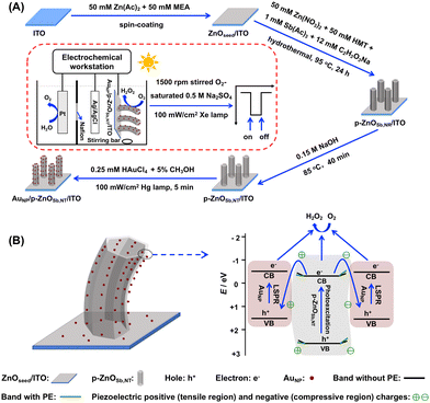
Herein, a novel AuNP/p-ZnOSb,NT/indium tin oxide (ITO) photocathode is prepared, and the green PPEC-ORR synthesis of H2O2 is investigated for the first time. As shown in Scheme 1A and discussed in detail in the ESI,† the AuNP/p-ZnOSb,NT/ITO photocathode is prepared by the following four steps: (1) spin coating to obtain a dense ZnO seed (ZnOseed) layer on an ITO substrate (ZnOseed/ITO); (2) hydrothermal Sb-doping to obtain a p-ZnOSb,NR/ITO electrode; (3) hot alkali solution etching to obtain a p-ZnOSb,NT/ITO electrode; and (4) PD of AuNP to obtain the AuNP/p-ZnOSb,NT/ITO photocathode. Through the reactions of O2 + 2H+ + 2e− = H2O2 at this photocathode and 2H2O = O2 + 4H+ + 4e− at a Pt anode, the high-performance PPEC-ORR synthesis of H2O2 is achieved, as discussed in detail later.
 | ||
| Scheme 1 Illustration of (A) the fabrication of the AuNP/p-ZnOSb,NT/ITO photocathode and the PPEC cell as well as (B) the possible electron transfer pathway during the PPEC-ORR synthesis of H2O2. | ||
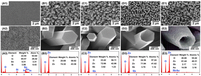
The bare ITO, n-ZnONR/ITO, p-ZnOSb,NR/ITO, p-ZnOSb,NT/ITO and AuNP/p-ZnOSb,NT/ITO electrodes were characterized by scanning electron microscopy (SEM) and energy dispersive spectroscopy (EDS), as shown in Fig. 1. The slightly rough surface of the bare ITO is due to the presence of silicon dioxide and ITO on the glass surface. The hexagonal prism n-ZnONR array was vertically arranged on the ITO surface, with a side length of ca. 300 nm and a height of ca. 2 μm. The morphology of p-ZnOSb,NR after Sb-doping is basically consistent with that of n-ZnONR. The p-ZnOSb,NT/ITO electrode was prepared by etching the p-ZnOSb,NR/ITO electrode in 0.15 M aqueous NaOH at 85 oC, and the optimized etching time was 40 min. As discussed in detail in Fig. S1 (ESI†), the top central section of the p-ZnOSb,NR hexagonal prism can be gradually etched by increasing the etching time, and a too long etching time will lead to further etching on the side of p-ZnOSb,NR, as reported for the etching of n-ZnONR into n-ZnONT.19 The AuNP/p-ZnOSb,NT/ITO surface became rougher due to the PD of many uniformly distributed AuNP. All of the corresponding EDS results have confirmed the expected elemental compositions. In addition, the bare ITO, n-ZnONR/ITO, p-ZnOSb,NR/ITO, p-ZnOSb,NT/ITO and AuNP/p-ZnOSb,NT/ITO electrodes were characterized by X-ray diffraction (XRD) spectroscopy, the AuNP/p-ZnOSb,NT/ITO electrode was characterized by X-ray photoelectron spectroscopy (XPS), and the p-ZnOSb,NT/ITO electrode was further characterized by piezoresponse force microscopy (PFM), as discussed in detail in Fig. S2–S4 (ESI†). All of the above results indicate the successful preparation of these electrodes.
 | ||
| Fig. 1 SEM images and EDS results of bare ITO (A1, A2, A3), n-ZnONR/ITO (B1, B2, B3), p-ZnOSb,NR/ITO (C1, C2, C3), p-ZnOSb,NT/ITO (D1, D2, D3), and AuNP/p-ZnOSb,NT/ITO (E1, E2, E3) electrodes. | ||
The ultraviolet-visible (UV-vis) diffuse reflectance spectra (DRS) of the n-ZnONR/ITO, p-ZnOSb,NR/ITO, p-ZnOSb,NT/ITO, AuNP/p-ZnOSb,NT/ITO and AuNP/ITO electrodes are shown in Fig. S5A (ESI†). The n-ZnONR/ITO electrode only absorbs ultraviolet light below ca. 390 nm. The red shift of the absorption range of the p-ZnOSb,NR/ITO electrode is due to the reduction of the band gap (Eg) after introducing new defect levels into ZnO by Sb-doping.20 The further red shift of the absorption range of the p-ZnOSb,NT/ITO electrode is due to the hollow structure of p-ZnOSb,NT with a reduced Eg, as reported for the etching of n-ZnONR into n-ZnONT.21 The AuNP/p-ZnOSb,NT/ITO electrode can absorb both ultraviolet and visible light due to the localized surface plasmon resonance (LSPR) effect of the AuNP.22 The photoluminescence (PL) spectra of the n-ZnONR/ITO, p-ZnOSb,NR/ITO, p-ZnOSb,NT/ITO, AuNP/p-ZnOSb,NT/ITO and AuNP/ITO electrodes are shown in Fig. S5B (ESI†). The emission peaks observed at ca. 380 nm and ca. 580 nm are due to the de-excitation of photoexcited electrons from the conduction band (CB) level (ca. 380 nm) and the defect level (ca. 580 nm) to the valence band (VB) level, respectively,23 and the rise and fall of the two emission peaks among these electrodes have been reasonably explained in Fig. S5 (ESI†). The UV-vis DRS curves are converted into the Tauc curves, and the Eg values are obtained as n-ZnONR/ITO (Eg = 3.22 eV), p-ZnOSb,NR/ITO (Eg = 3.12 eV), p-ZnOSb,NT/ITO (Eg = 3.06 eV) and AuNP/ITO (Eg = 2.13 eV), as discussed in detail in Fig. S5C (ESI†). The VB XPS experiments gave EVB = 2.60 eV and ECB = −0.46 eV for p-ZnOSb,NT/ITO electrode, as well as EVB = 1.57 eV and ECB = −0.56 eV for AuNP/ITO electrode, as discussed in detail in Fig. S6 (ESI†). In addition, the electrochemical impedance spectroscopy (EIS) of the bare ITO, n-ZnONR/ITO, p-ZnOSb,NR/ITO, p-ZnOSb,NT/ITO and AuNP/p-ZnOSb,NT/ITO electrodes in 0.5 M aqueous Na2SO4 containing 2.0 mM K4[Fe(CN)6], and the effects of illumination and/or solution-stirring on the electron transfer resistance (Ret) of AuNP/p-ZnOSb,NT/ITO electrode, were studied. The rationality of the obtained Ret values is discussed in detail in Fig. S7 (ESI†).
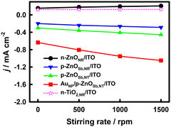
The effects of the solution-stirring rate on the PPEC-ORR performance of the n-type TiO2 NR (n-TiO2,NR)/ITO, n-ZnONR/ITO, p-ZnOSb,NR/ITO, p-ZnOSb,NT/ITO and AuNP/p-ZnOSb,NT/ITO electrodes at 0.4 V vs. RHE in O2-saturated 0.5 M aqueous Na2SO4 were investigated, as shown in Fig. 2. With the increase in the solution-stirring rate from 0 rpm to 1500 rpm (the largest stirring rate of our equipment, by which the PEC cell can be somewhat shaken, and an overlarge stirring rate may damage the nanostructures of the photoelectrodes), the photocurrent densities (absolute values) of the four piezoelectrically active ZnO-based electrodes increased, while the photocurrent density of the piezoelectrically inactive n-TiO2,NR/ITO electrode remained basically unchanged, indicating that the solution-stirring-enhanced mass transfer hardly affects the PEC responses here, as reported for WO3−x/n-ZnONR/FTO, n-ZnONR/FTO and n-TiO2,NR/FTO photoelectrodes.10 At a 1500 rpm stirring rate, the photocurrent densities (absolute value) follow the order AuNP/p-ZnOSb,NT/ITO (−1.05 mA cm−2) > p-ZnOSb,NT/ITO (−0.456 mA cm−2) > p-ZnOSb,NR/ITO (−0.288 mA cm−2) > n-ZnONR/ITO (0.185 mA cm−2) > n-TiO2,NR/ITO (0.134 mA cm−2). The positive anodic photocurrent densities at the n-ZnONR/ITO and n-TiO2,NR/ITO photoelectrodes indicate the failure of the ORR on the two photoelectrodes. The dark current densities on all of these photoelectrodes were very small either with or without solution-stirring (not shown), indicating that illumination is the key factor in generating the current signal.
For the AuNP/p-ZnOSb,NT/ITO electrode at 0.4 V vs. RHE, the photocurrent densities remained at 93.2% and 94.4% of the original values after 24 h of PPEC-ORR under continuous and intermittent illumination, respectively, indicating the good stability of the AuNP/p-ZnOSb,NT/ITO electrode, as shown in Fig. S8 (ESI†). The concentrations of H2O2 were determined by UV-vis spectrophotometry, which are in good agreement with those obtained by cyclic voltammetry (CV) on an Au disk electrode, and the CV curves with specific H2O2-oxidation/reduction peaks have solidly confirmed the PPEC-ORR production of H2O2 in the photocathode compartment, as discussed in detail in Fig. S9 (ESI†). For 1 h PPEC-ORR on the AuNP/p-ZnOSb,NT/ITO electrode, the H2O2 yield was 15.2 μmol cm−2 h−1 (1.52 mM cm−2 h−1) and the Faraday efficiency was 79.0%, as discussed in detail in Fig. S10 (ESI†). The H2O2 yield on the AuNP/p-ZnOSb,NT/ITO PPEC photocathode is higher than those of many reported PEC photocathodes, as listed in Table S2 (ESI†).
The open circuit potential (VOC)-time (t) and Mott–Schottky curves of the n-ZnONR/ITO, p-ZnOSb,NR/ITO, p-ZnOSb,NT/ITO and AuNP/p-ZnOSb,NT/ITO electrodes are discussed in detail in Fig. S11–S13 (ESI†). The largest photoelectron lifetime (τ, 35 ns) and photogenerated carriers density (N, 5.85 × 1021 cm−3) values are obtained on the AuNP/p-ZnOSb,NT/ITO electrode at a 1500 rpm solution-stirring rate, and increasing the stirring rate can increase the τ value on this electrode, implying the best PPEC performance on the AuNP/p-ZnOSb,NT/ITO electrode at 1500 rpm.
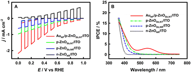
The linear sweep voltammetry (LSV) curves on the n-ZnONR/ITO, p-ZnOSb,NR/ITO, p-ZnOSb,NT/ITO and AuNP/p-ZnOSb,NT/ITO electrodes are shown in Fig. 3A. The n-ZnONR/ITO electrode gave a positive anodic photocurrent density, implying the impossibility of PEC-ORR synthesis of H2O2 on the n-ZnO based electrode. In contrast, the p-ZnOSb,NR/ITO, p-ZnOSb,NT/ITO and AuNP/p-ZnOSb,NT/ITO electrodes gave negative cathodic photocurrent densities that were increased with the negative shift of potential, proving the feasibility of the PEC-ORR synthesis of H2O2 on all of these p-ZnOSb based electrodes. Considering the dark current to be as small as possible and the aforementioned theoretical potentials for electroreduction of H2O and O2, the applied potential is chosen as 0.4 V vs. RHE.
The incident photon–electron conversion efficiency (IPCE) curves of the n-ZnONR/ITO, p-ZnOSb,NR/ITO, p-ZnOSb,NT/ITO and AuNP/p-ZnOSb,NT/ITO electrodes are shown in Fig. 3B. As expected, the AuNP/p-ZnOSb,NT/ITO electrode of the best PPEC-ORR performance gave the largest IPCE. On the AuNP/p-ZnOSb,NT/ITO electrode, the IPCE-derived total photocathodic photocurrent density is −0.774 mA cm−2 (365–800 nm), which is, as expected, smaller than but still comparable to the experimental PPEC photocurrent density of −1.05 mA cm−2 (300–1100 nm), indicating the reliability of the photocurrent density data on the AuNP/p-ZnOSb,NT/ITO electrode, as discussed in detail in Fig. S14 (ESI†).
A superoxide radical trapping experiment based on the nucleophilic substitution reaction between an acid halide and superoxide was performed,24 as discussed in detail in Fig. S15 (ESI†). The results suggest that O2˙− is an important intermediate in the PPEC-ORR process.16
The high performance PPEC-ORR synthesis of H2O2 on the AuNP/p-ZnOSb,NT/ITO electrode can be explained as follows. (1) Effectiveness of the p-type ZnO semiconductor: the use of p-ZnOSb,NT that is prepared by doping Sb into n-ZnONR favorably enables the effective PEC-ORR synthesis of H2O2 (Fig. 2 and 3A), as reported in the literature where n-type and p-type semiconductors are employed to fabricate photoanodes and photocathodes, respectively.6,16,23 (2) The positive role of AuNP:16 both the inner and outer surfaces of p-ZnOSb,NT can form a Schottky-heterojunction structure with AuNP, and the weak AuNP-O2 coordination interaction may help the chemical catalysis for the PEC-ORR synthesis of H2O2. AuNP with a LSPR effect can harvest visible light to improve the PEC performance. The possible electron transfer pathway for H2O2 synthesis is shown in Scheme 1B. Knowing that EVB = 2.60 eV and ECB = −0.46 eV for p-ZnOSb,NT/ITO electrode, EVB = 1.57 eV and ECB = −0.56 eV for AuNP/ITO electrode (Fig. S5 and S6, ESI†), and the work function values are 4.85 eV for p-ZnOSb and 5.10 eV for AuNP,25,26 thus the photogenerated electrons on the CB of low-work-function p-ZnOSb,NT can be transferred to the VB of high-work-function AuNP, and the reduction of O2 to H2O2 by the photogenerated electrons on the CB levels of AuNP and p-ZnOSb,NT can occur. (3) Piezoelectrically enhanced PEC performance:7,8 as shown in Fig. S4 (ESI†) and Scheme 1B, p-ZnOSb,NT/ITO has good piezoelectric activity, thus p-ZnOSb,NT can be bent by solution-stirring to generate directional piezoelectric electric fields on the inner and outer surfaces of p-ZnOSb,NT. The energy band of ZnO can be bent upwards by the enrichment of negative piezoelectric charges in the compression region, and it can be bent downwards by the enrichment of positive piezoelectric charges in the stretching region. Logically, the separation of photogenerated charges in p-ZnOSb,NT can be improved by the electrostatic interactions between photogenerated and piezoelectric charges, and the interfacial Schottky barriers can also be modulated by the piezoelectric electric field towards the effective separation and transfer of photogenerated charges, thus facilitating the ORR with the photogenerated electrons on the p-ZnOSb,NT and AuNP surfaces to generate H2O2.
In conclusion, the AuNP/p-ZnOSb,NT/ITO photocathode has been prepared by hydrothermal Sb-doping into the n-ZnO NR array, hot alkali solution etching of p-ZnOSb,NR, and PD of AuNP. The PPEC-ORR synthesis of H2O2 has been studied for the first time. At 0.4 V vs. RHE under 100 mW cm−2 AM 1.5G simulated sunlight in 1500 rpm-stirred O2-saturated 0.5 M aqueous Na2SO4, the AuNP/p-ZnOSb,NT/ITO photocathode gave a H2O2 yield of 15.2 μmol cm−2 h−1, a photocurrent density of −1.05 mA cm−2, and a Faraday efficiency of 79.0%. The good PPEC performance has been explained mainly by the Sb doping to form p-ZnOSb,NT for the effective photoreduction of O2, the PD of LSPR-active AuNP on the inner and outer surfaces of p-ZnOSb,NT to harvest visible light, form Schottky heterojunctions and thus improve the PEC performance, and the formation of a piezoelectric directional electric field in p-ZnOSb,NT to facilitate the separation and transfer of the photogenerated charges. This research on the novel AuNP/p-ZnOSb,NT/ITO photocathode and the novel PPEC-ORR application, including the first-time introduction of NT into the PPEC field, may have paved a new avenue to develop PPEC materials and applications.
This work was supported by the National Natural Science Foundation of China (22074039, 21675050).
Conflicts of interest
There are no conflicts to declare.Notes and references
- Y. Nosaka and A. Y. Nosaka, Chem. Rev., 2017, 117, 11302–11336 CrossRef CAS PubMed.
- R. Noyori, M. Aoki and K. Sato, Chem. Commun., 2003, 1977–1986 RSC.
- Y. Y. Sun, L. Han and P. Strasser, Chem. Soc. Rev., 2020, 49, 6605–6631 RSC.
- J. M. Campos-Martin, G. Blanco-Brieva and J. L. G. Fierro, Angew. Chem., Int. Ed., 2006, 45, 6962–6984 CrossRef CAS PubMed.
- R. J. Lewis and G. J. Hutchings, ChemCatChem, 2019, 11, 298–308 CrossRef CAS.
- Y. F. Lei, S. B. Lei and L. Y. Piao, Prog. Chem., 2021, 33, 66–77 CAS.
- Z. L. Wang, Nano Today, 2010, 5, 540–552 CrossRef CAS.
- Y. H. Yu and X. D. Wang, Adv. Mater., 2018, 30, 1800154 CrossRef.
- L. Pan, S. C. Sun, Y. Chen, P. H. Wang, J. Y. Wang, X. W. Zhang, J. J. Zou and Z. L. Wang, Adv. Energy Mater., 2020, 10, 2000214 CrossRef CAS.
- Y. Chen, L. Wang, R. J. Gao, Y. C. Zhang, L. Pan, C. Y. Huang, K. Liu, X. Y. Chang, X. W. Zhang and J. J. Zou, Appl. Catal., B, 2019, 259, 118079 CrossRef CAS.
- S. C. Zhang, Z. F. Liu, M. N. Ruan, Z. G. Guo, E. Lie, W. Zhao, D. Zhao, X. F. Wu and D. M. Chen, Appl. Catal., B, 2020, 262, 118279 CrossRef CAS.
- H. N. Hieu, N. V. Nghia, N. M. Vuong and H. Van Bui, Chem. Commun., 2020, 56, 3975–3978 RSC.
- F. Wang, J. H. Seo, D. Bayerl, J. A. Shi, H. Y. Mi, Z. Q. Ma, D. Y. Zhao, Y. C. Shuai, W. D. Zhou and X. D. Wang, Nanotechnology, 2011, 22, 225602 CrossRef.
- C. Cao, X. X. Xie, Y. M. Zeng, S. H. Shi, G. Z. Wang, L. Yang, C. Z. Wang and S. W. Lin, Nano Energy, 2019, 61, 550–558 CrossRef CAS.
- S. M. Lee, S. H. Shin, J. Nah and M. H. Lee, Nanotechnology, 2017, 28, 395403 CrossRef PubMed.
- C. Chen, M. Yasugi, L. Yu, Z. Y. Teng and T. Ohno, Appl. Catal., B, 2022, 307, 121152 CrossRef CAS.
- R. Lv, T. Wang, F. Su, P. Zhang, C. Li and J. Gong, Nano Energy, 2014, 7, 143–150 CrossRef CAS.
- J. T. Song, H. Ryoo, M. Cho, J. Kim, J. G. Kim, S. Y. Chung and J. Oh, Adv. Energy Mater., 2017, 7, 160103 Search PubMed.
- X. Y. Gan, X. M. Li, X. D. Gao and W. D. Yu, J. Alloys Compd., 2009, 481, 397–401 CrossRef CAS.
- J. K. Liang, H. L. Su, C. L. Kuo, S. P. Kao, J. W. Cui, Y. C. Wu and J. C. A. Huang, Electrochim. Acta, 2014, 125, 124–132 CrossRef CAS.
- W. C. Lee, Y. X. Fang, R. Kler, G. E. Canciani, T. C. Draper, Z. T. Y. Al-Abdullah, S. M. Alfadul, C. C. Perry, H. Y. He and Q. Chen, Mater. Chem. Phys., 2015, 149, 12–16 CrossRef.
- X. Zhang, Y. Liu and Z. H. Kang, ACS Appl. Mater. Interfaces, 2014, 6, 4480–4489 CrossRef CAS.
- Z. J. Bao, X. Y. Xu, G. Zhou and J. G. Hu, Nanotechnology, 2016, 27, 305403 CrossRef.
- J. N. Sun, Y. Z. Yu, A. E. Curtze, X. C. Liang and Y. Y. Wu, Chem. Sci., 2019, 10, 5519–5527 RSC.
- L. J. Mandalapu, F. X. Xiu, Z. Yang and J. L. Liu, J. Appl. Phys., 2007, 102, 023716 CrossRef.
- Y. Kim, J. G. Smith and P. K. Jain, Nat. Chem., 2018, 10, 763–769 CrossRef CAS PubMed.
Footnote |
| † Electronic supplementary information (ESI) available. See DOI: https://doi.org/10.1039/d2cc05424h |
| This journal is © The Royal Society of Chemistry 2023 |


