
Improvement in the output performance of polyethylene oxide-based triboelectric nanogenerators by introducing core–shell Ag@SiO2 particles†
Xu
Liu
,
Xiao-Rong
Sun
,
Chen
Luo
,
Hong-Zhi
Ma
,
Hua
Yu
,
Yan
Shao
*,
Ming-Bo
Yang
 and
Bo
Yin
*
and
Bo
Yin
*
College of Polymer Science and Engineering, State Key Laboratory of Polymer Materials Engineering, Sichuan University, Chengdu, 610065, Sichuan, China. E-mail: yinbo@scu.edu.cn
First published on 23rd November 2021
Abstract
The development of self-powered technology in nano-energy puts forward higher requirements for triboelectric nanogenerators (TENGs), in which it is necessary to further improve their output performance to broaden their scope of application, and environmentally friendly and sustainable development needs to be realized as well by the recycling of friction materials. The preparation of environmentally friendly and sustainable TENGs is reported in this work through a feasible and cost-effective solution casting method, in which polyethylene oxide (PEO) and Ecoflex were utilized as positive/negative friction materials, respectively. With introducing micron-sized core–shell Ag@SiO2 particles into the PEO matrix, micro–nano structures were constructed to increase the effective contact area, while the enhancement of dielectric properties was also achieved in the meantime. The Ag@SiO2–PEO/Ecoflex TENG with optimum particle content of 50 wt% produced a short-circuit current of 10 μA, an open-circuit voltage of 95 V, and a transfer charges of 35 nC at a frequency of 3 Hz. The maximum output power density of Ag@SiO2–PEO-50 wt%/Ecoflex TENG up to 1.5 W m−2 was reached under different load resistances. The stability and flexibility of TENGs were verified as well, which led to a novel approach for their application in wearable-flexible electronic devices. Additionally, the sustainable utilization of TENGs was achieved as a result of the water solubility of the PEO material, with significant output performance retention. This work provides an innovative approach for the further modification of the output performance of flexible and sustainable TENGs.
1. Introduction
Electronic devices are developing towards miniaturization, mobility, and multi-function, which brings an urgent demand to provide energy for large quantity, wide distribution, and low-energy-expenditure devices.1 Triboelectric nanogenerators (TENGs) can convert different types of mechanical energy into electricity, providing a potential approach to meet the rapidly increasing energy demands.2 Recently, a large number of TENGs have been developed to harvest energy from the natural environment.3–5 From the point of practical application, the output performance of TENGs should be as high as possible. Given this situation, a great deal of research has focused on the improvement of the output performance of TENGs.6–8There are several methods to improve the output performance of TENGs. Increasing the effective contact area between friction materials is one adequate means for the improvement of the output performance.9 The surface morphologies of friction materials are commonly modified by templating,10 appending,11 crumpling,12 and etching13 methods, which can increase the effective contact area and friction electrification effect to varying degrees.14 The chemical modification of friction materials has also been utilized to realize surface functionalization, which can significantly change the surface potential of friction materials, for example, increasing the electron affinity of surface atoms by surface fluorination,15 introducing additional charged ions to increase the triboelectric charge density,16 and regulating the surface charge density of friction materials caused by molecular-targeting functionalization.17 It is undeniable that these reported works have made great progress on the improvement of the output performance to extend the applications of TENGs. However, the typically complicated preparation process and requirement for sophisticated equipment limit their wide applications.
Introducing functional particles into friction materials is another concise approach to improve the output performance of TENGs, in which the incorporation of functional particles can enhance the dielectric properties of friction materials to increase the surface charge density.18–20 The introduced functional particles can be chiefly divided into conductor and insulator types.21,22 However, metal conductive particles will not only cause particle agglomeration due to their large specific surface area and high surface tension, but will form conductive pathways in the composite matrix, thus resulting in serious seepage current.23 On the other hand, the promotion effect on the dielectric properties of friction materials with high insulator particles content is limited. Furthermore, a high filling content will cause a large number of hole defects in the composite materials.24 Therefore, it is necessary to effectively improve the high dielectric properties of friction materials on the premise of uniform particle dispersion.
TENG is an environmentally friendly technology to harvest clean and renewable energy from the natural environment, such as human motion,25 wind,26 and blue energy.27 Nevertheless, a large amount of work has focused on the improvement of the output performance of TENGs to make it as high as possible14,28,29 or on various forms of energy harvesting through microstructure modulation,30–32 with only little attention paid so far to the sustainability of TENGs, owing to the biodegradability of the friction materials.33–35 Besides, most of the reported TENGs consist of nondegradable and nonrenewable friction materials, which will significantly compromise the overall sustainability of the TENGs.36–38 Beyond that, more sustainable materials need to be highly designed to fully realize the potential of TENGs as sustainable energy harvesters.
Based on the above considerations, environmentally friendly and sustainable TENGs with excellent output performance were prepared here by a simple and scalable method. Polyethylene oxide (PEO) and Ecoflex were chosen as the positive/negative friction materials, respectively, based on the difference in their electronegativity, in which the oxygen functional groups on the surface of PEO films can provide a positive charge,39,40 while Ecoflex has strong electronic affinity owing to its similar chemical structure with polydimethylsiloxane (PDMS).41,42 It is worth noting that the desirable water solubility of the PEO material provides a possibility for the realization of the sustainable utilization of the obtained TENGs. In order to improve the output performance, core–shell Ag@SiO2 particles were introduced into the PEO matrix. Significantly, the core–shell structure of the Ag@SiO2 particles could effectively prevent the Ag nanoparticles from undergoing massive aggregation in the polymer matrix and reduce the possibility of forming conductive pathways to maintain the excellent insulation of the friction materials.43 These micron-sized particles were encapsulated by the PEO matrix to form convex structures that increased the effective contact area. Besides, the Ag@SiO2 particles could enhance the dielectric properties effectively with homogeneous dispersion. In this work, the improvement of the dielectric properties and increase in the effective contact area were achieved simultaneously with the introduction of the micron-sized core–shell Ag@SiO2 particles. Subsequently, the output performance of the Ag@SiO2–PEO/Ecoflex TENG with an optimum particles content of 50 wt% was effectively improved about two-fold higher than the pristine PEO-based TENG, owing to the synergistic effect. The stability and flexibility of the friction materials make it possible for the TENGs to be utilized as power supply equipments for wearable electronic devices. Based on the bio-compatibility and water solubility of the PEO material, the sustainable utilization of the PEO-based TENGs was also evaluated. As a result, the Ag@SiO2–PEO/Ecoflex TENG can be regarded as a recyclable power-supply system to realize the sustainable operation of micro/nano-systems.
2. Experimental section
2.1. Materials
![[thin space (1/6-em)]](https://www.rsc.org/images/entities/char_2009.gif) :1, followed by a degassing process in vacuum at room temperature (25 °C) with the avoidance of curing. The resulting Ecoflex mixtures were cast on glass substrates with a thickness of 100 μm, and cured at 80 °C for 6 h. Similarly, the cured Ecoflex films were stripped off from the glass substrates, cut, and stuck on the adhesive Cu electrodes.
:1, followed by a degassing process in vacuum at room temperature (25 °C) with the avoidance of curing. The resulting Ecoflex mixtures were cast on glass substrates with a thickness of 100 μm, and cured at 80 °C for 6 h. Similarly, the cured Ecoflex films were stripped off from the glass substrates, cut, and stuck on the adhesive Cu electrodes.
2.2. Material characterizations
The morphologies of the Ag@SiO2/PEO films and the Ag@SiO2 particles were observed by field-emission scanning electron microscopy (SEM, NanoSEM 450, FEI). Laser scanning confocal microscopy (LSCM, LSM880 Airyscan with Stedycon, Zeiss) was utilized to characterize the surface roughness of the composite films qualitatively. The chemical composition of the surface of the Ag@SiO2 particles was analyzed by X-ray photoelectron spectroscopy (XPS, XSAM800, Kratos).A four-point probe operation (RTS-2, 4 Probes Tech) and digital multimeter (2400, Keithley Instruments) measurement system was utilized to calculate the conductivity of the Ag@SiO2/PEO films with dimensions of 30 mm × 30 mm × 100 μm. A broadband dielectric/impedance spectrometer (Concept 50, Navocontrol Technologies) was applied to measure the variation on the dielectric constant of the Ag@SiO2/PEO films in a certain frequency range.
The tensile tests of the friction materials were operated on a Universal testing machine (5565, Instron) at room temperature (25 °C), in which the tensile rate was set as 10 mm min−1.
2.3. Output performance characterization
A high-resistance/low-current electrometer (6514, Keithley) and linear motor (P01-37X120-C_C1, Linmot) test system was utilized to characterize the output performance of the TENGs with effective test dimensions of 2 cm × 2 cm, in which the contact–separation reciprocating motions of the TENGs were driven by the linear motor. The output signals were obtained by the electrometer and the transfer charges were calculated by integral calculation. Additionally, the output performance measurements were carried out under the test condition of 25–27 °C, 40–60% relative humidity (RH).3. Results and discussion
The charge-transfer level between the positive and negative materials depends on the polarity discrepancy of friction materials.44 Therefore, the intrinsic properties of triboelectric materials have a significant influence on the output performance of TENGs. PEO and Ecoflex here respectively served as positive and negative friction materials because of their different polarities. PEO shows excellent positive polarity in the triboelectric series due to its chemical structure. The oxygen functional groups exposed on the surface endow PEO with the ability to provide positive charge.39,40 Additionally, the C–O–C and –OH chemical bonds in the chemical structure show electron repulsion owing to the low electron affinity of the H atom, which also indicates an excellent positive polarity in the triboelectric series.45,46 On the other hand, Ecoflex, which is analogous to PDMS in chemical structure, has been proved to have high electronegativity.41 In order to enhance the output performance of the TENGs, micron-sized Ag@SiO2 particles were introduced in to the PEO matrix to increase the surface roughness as well as the dielectric properties of the PEO-based composite films.Fig. 1a shows the SEM images of the Ag@SiO2 particles, where it can be seen that the Ag layers were uniformly coated on the surface of the silica microspheres to form the core–shell Ag@SiO2 particles. Additionally, the average size of the micron-sized particles was 16.23 μm as determined through the particle-size distribution, as shown in Fig. 1b. The chemical composition of the surface of the Ag@SiO2 particles was obtained by XPS analysis, as shown in Fig. S1 (ESI†). Peaks representing –Si–O– (532.5 eV), –Si–O– (103.0 eV), and –Na2O–SiO2– (1071.8 eV) were observed for the silica microspheres, implying a little residual sodium silicate in the preparation of the silica microspheres. At the same time, the signal of Ag 3d and the peak centered around 97.0 eV for Ag 4s directly indicated the existence of the Ag shells on the surface of the Ag@SiO2 particles. From the above XPS analysis, it is suggested that the structure of the core–shell particles with the Ag layers coating on the surface of the silica microspheres could be further confirmed. The core–shell Ag@SiO2 structure could be regarded as involving abundant Ag nanoparticles attached to the surface of silica microspheres with good dispersion in the polymer matrix, which not only improves the dispersion of particles to prevent the seepage phenomenon caused by particle aggregation, but also ensures the original stability and activity of the metal nanoparticles.47–49
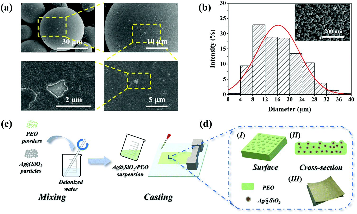 | ||
| Fig. 1 (a) SEM images of the surface of the Ag@SiO2 particles with different magnifications. (b) Histogram of the particle-size distribution of the Ag@SiO2 particles. (c) Preparation of the Ag@SiO2/PEO films. (d) Schematic diagram and physical picture of the morphology of the Ag@SiO2/PEO films. | ||
Fig. 1(c and d) show a schematic diagram of the Ag@SiO2/PEO films fabrication process, in which the well-mixed Ag@SiO2/PEO aqueous solutions were cast on the flat surface through the solution-casting method. Subsequently, the Ag@SiO2/PEO composite films with a thickness of 100 μm were easily formed. As shown in Fig. S2 (ESI†), the SEM images of the cross-section of the composite films demonstrate that the Ag@SiO2 particles were uniformly dispersed in the PEO matrix, and no obvious particles agglomeration phenomenon could be observed, especially for the films with a high particles content.
3.1. Surface morphologies
The intrinsic properties of triboelectric materials have a marked impact on the output performance of TENGs. Therefore here, the characteristic properties of the Ag@SiO2/PEO composite films were studied first. SEM was utilized to characterize the surface morphologies of the Ag@SiO2/PEO films, as shown in Fig. 2(a–d). The casting pristine PEO film was relatively uniform and flat. However, some crackles could be observed on the surface. It was speculated that this phenomenon can be explained as the local shrinkage of the surface of the PEO films, which was caused by the crystallization of the PEO molecular chains during the evaporation of deionized water. After the introduction of the particles, convex structures were formed by the Ag@SiO2 particles wrapped in the PEO matrix, which could be distinctly observed. Additionally, the number of convex structures on the surface of the composite films increased with the increase in the particles content, which had a more remarkable effect on the surface roughness of the composite films.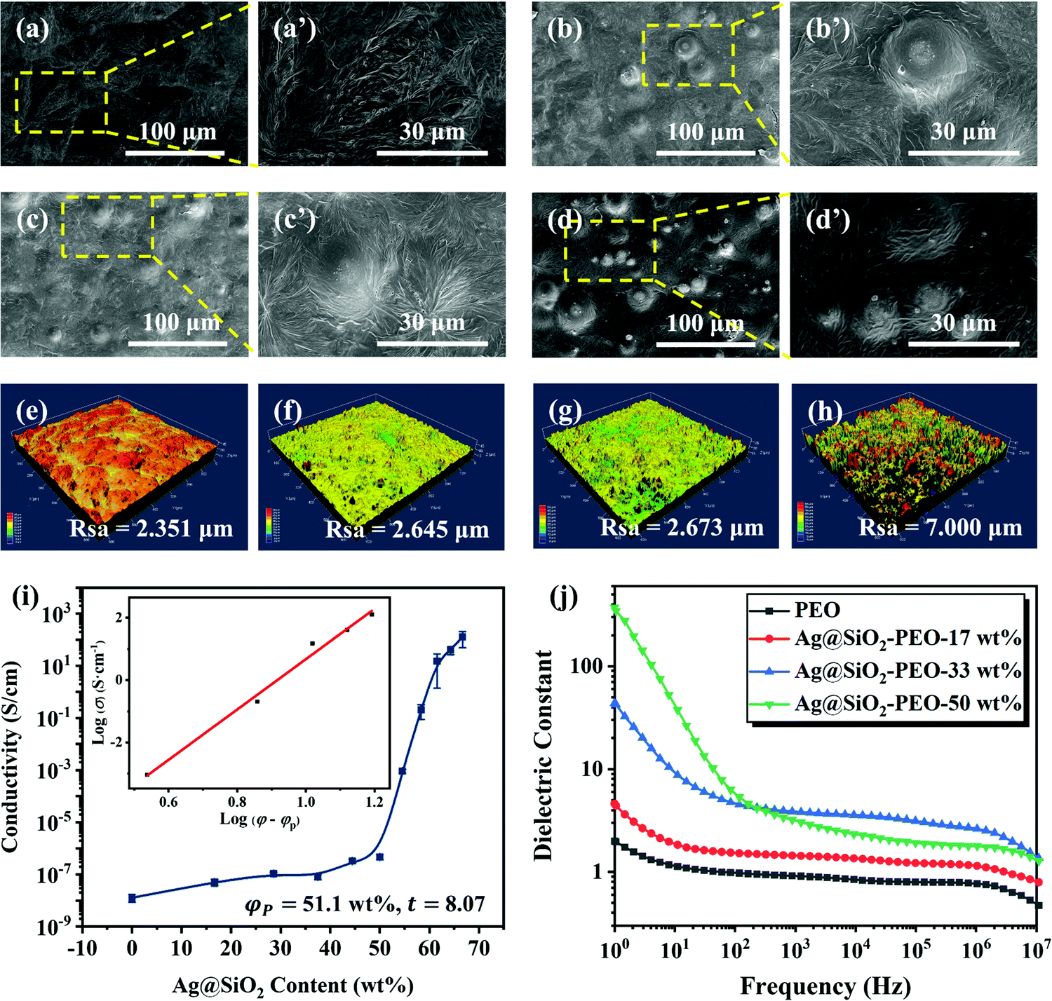 | ||
| Fig. 2 SEM images of the surface of (a) the PEO film and the Ag@SiO2/PEO films with different contents of Ag@SiO2 particles with different magnifications: (b) 17 wt%, (c) 33 wt%, and (d) 50 wt%. LSCM images of the surface of (e) the PEO film and the Ag@SiO2/PEO films with different contents of Ag@SiO2 particles with scanning dimensions of 600 μm × 600 μm: (f) 17 wt%, (g) 33 wt%, and (h) 50 wt %. (i) Electrical conductivity of the Ag@SiO2/PEO films dependence on the Ag@SiO2 particles content. (j) Variations in the dielectric constant of the Ag@SiO2/PEO films with different Ag@SiO2 particles contents in the frequency range of 100–107 Hz. | ||
LSCM was used to further explain the improvement effect of the Ag@SiO2 particles on the surface roughness of the composite films quantitatively, as shown in Fig. 2(e–h). The surface roughness (Rsa) of the pristine PEO film was 2.531 μm as a result of the crystallization of the PEO molecular chains. With the introduction of the Ag@SiO2 particles into the PEO matrix, the surface roughness of the composite films increased significantly. Additionally, the surface roughness increased continuously with the increase in the Ag@SiO2 particles content. When the particles content reached 50 wt%, a surface roughness of the composite film up to 7.000 μm could be achieved. Consequently, the effective contact area between the friction materials increased, remarkably improving the output performance of the TENGs, owing to the positive correlation between the effective contact area and output performance.
3.2. Dielectric properties
With the exception of the effective contact area, the dielectric constant of friction materials also plays an imperative role on the surface charge density.50 The relationship between the dielectric constant (ε) and surface charge density (σc) is as follows,51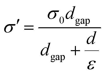 | (1) |
Studies have reported that the dielectric constant of composite films can be increased dramatically when the content of the introduced conductive particles is close to the electrical percolation threshold (φp).52 Conversely, the output performance of TENGs will be weakened owing to triboelectric charge leakage on the surface of friction materials via the conductive pathways formed between the surface of the friction layer and electrode material, on account of the conductivity of composite films caused by the introduction of conductive particles at a certain content.43
According to the above analysis, the conductivity of the Ag@SiO2/PEO films depending on the Ag@SiO2 particles content was investigated before the measurement of the dielectric properties of the composite films. The percolation curve is shown in Fig. 2i, in which the test data were fitted by the power-law equation. The results show that the electrical percolation threshold of the Ag@SiO2/PEO films was 51.5 wt%. This indicated that a three-dimensional conductive network was constructed in the composite films when the particles content reached 51.5 wt%. Consequently, the maximum content of the Ag@SiO2 particles was set at 50 wt% to avoid the seepage phenomenon in this work.
The relationship between the Ag@SiO2 particles content and the dielectric constant of the Ag@SiO2/PEO films is shown in Fig. 2j. The dielectric constant of the composite films increased dramatically in the whole frequency range following introducing the functional particles, which could be attributed to the polarization of the conductive particles in the composite films.53 With the increase in the Ag@SiO2 particles content, the dielectric constant of the composite films generally showed an upward tendency, especially in the low frequency region. This is because the distance between adjacent particles becomes shorter with the increase in the Ag@SiO2 particles content, and the micro-capacitor structures formed between the adjacent particles on the dielectric then have a more significant effect on the dielectric constant. Thus, a large amount of polarization charges can be stored in the electric field, greatly improving the dielectric properties of the composite films.47,48 Nonetheless, the dielectric constant of the Ag@SiO2–PEO-50 wt% film was anomalous in the high frequency region owing to the enhancement of the electron-transmission capacity. Thereupon, the polarized charges captured by the interface and its defects between the Ag@SiO2 particles and the PEO matrix are then reduced, and the interfacial polarization is decreased as well.53
3.3. Charge-generation mechanism
The TENGs presented here work in the vertical contact–separation mode, which is illustrated in Fig. 3. The operation principle of the TENGs can be attributed to the coupling effect of contact electrification and electrostatic induction.51,54 In the initial state, there is no potential difference between the positive/negative materials. However, when there is an external displacement, the surfaces of the positive/negative materials contact each other. As a result of a triboelectrification effect, charge transfer occurs in the contact part of the friction materials. According to the discrepancy in the electronegativity between the friction materials, the charge on the surface of the Ag@SiO2/PEO films will be transferred to the surface of the Ecoflex films, which makes the Ag@SiO2/PEO films have positive charge and the Ecoflex films negative charge (Fig. 3a). By virtue of the insulation of the friction materials, the induced charges are preserved on the surfaces of the films. When the external force on the TENGs is unloaded, the friction materials tend to return to the initial position owing to elastic recovery. In this way, the charged surfaces of the positive/negative materials are separated from each other, thus forming potential difference. Afterwards, the potential difference between the two friction materials drives the charges moving from the negative material to the positive material, which results in a positive instantaneous current generated in the process of friction materials separation (Fig. 3b). The charges transferred to the Ecoflex films are retained because of the intrinsic energy barrier of the friction materials (Fig. 3c). The gap between the positive and negative materials is decreased when the TENGs are re-applied with an external force, resulting in the potential of the Ecoflex films to be higher than that of the Ag@SiO2/PEO films. The charges flow from the positive material to the negative material, and the induced charges on the surface of the friction materials are reduced in the meantime. Consequently, an instantaneous current in the negative direction is formed in this process (Fig. 3d). When the positive/negative materials contact again, all the induced charges are then neutralized. | ||
| Fig. 3 Schematic of the operation principle of the TENGs in vertical contact–separation mode. | ||
3.4. Output performance
On the basis of the above results, the introduction of the Ag@SiO2 particles is advantageous to increasing the surface roughness and enhancing the dielectric properties as well. Conclusively, the output performance of the TENGs will be improved significantly. In terms of the above analysis, the output performance of the TENGs could be directly studied.The output performance of the Ag@SiO2–PEO/Ecoflex TENGs with different Ag@SiO2 particles content is shown in Fig. 4(a–c). It can be seen that the short-circuit current, the open-circuit voltage and the transfer charges of the PEO/Ecoflex TENG without introducing the Ag@SiO2 particles were about 5 μA, 52 V and 17 nC, respectively. With the increase in the particles content in the composite films, the output performance of the TENGs was improved significantly. When the Ag@SiO2 particles content reached 50 wt%, the short-circuit current, the open-circuit voltage and the transfer charges of the Ag@SiO2–PEO-50 wt%/Ecoflex TENG were about 10 μA, 95 V and 35 nC, respectively, which were 2.0, 1.8 and 2.1 times higher than the sample without the introduction of the Ag@SiO2 particles. It is presumed that the output performance improvement of the TENGs benefited from the synergistic effect of the enhancement of the surface roughness and the dielectric properties. Nevertheless, further increasing the Ag@SiO2 particles content did not significantly improve the output performance, as shown in Fig. S3(a–c) (ESI†), which was maybe related with the seepage current caused by the high filling content.
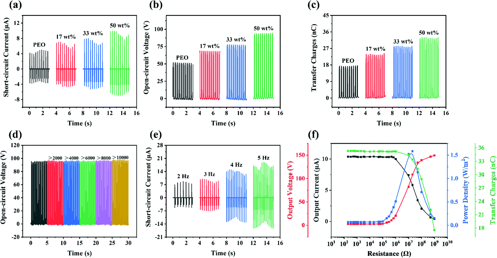 | ||
| Fig. 4 Output performance of the Ag@SiO2–PEO/Ecoflex TENGs: (a) short-circuit current, (b) open-circuit voltage and (c) transfer charges of the Ag@SiO2/PEO films-based TENGs with different Ag@SiO2 particles contents. (d) Output stability of the Ag@SiO2–PEO-50 wt% film-based TENG under cycling measurement over 10000 times. (e) Short-circuit current of the Ag@SiO2–PEO-50 wt% film-based TENG under different test frequencies. (f) Instantaneous peak value of the output current, the output voltage and the transfer charges, and the instantaneous power density of the Ag@SiO2–PEO-50 wt% film-based TENG dependence for different load resistances. | ||
Excellent stability and durability of the Ag@SiO2–PEO-50 wt%/Ecoflex TENG were confirmed as well, in which the open-circuit voltage remained stable over 10000 cycles as shown in Fig. 4d. It should be noted that the test frequency was set as 3 Hz unless otherwise stated in this work. Additionally, the favorable stability of the positive material was further confirmed in Fig. S4 (ESI†), compared with the surface morphologies of the PEO composite film before and after the cycling measurement, for which there was no significant effect on the surface structure of the friction materials in the vertical contact–separation process. On the other hand, the outstanding flexibility of the friction materials determined by tensile strength and elongation at break is demonstrated in Table S1 and Fig. S5 (ESI†). Collectively, the stability and flexibility of the Ag@SiO2/PEO films indicated their application prospect for efficient energy collection or as storage equipment for wearable electronic devices.
Additionally, the effect of the test frequency on the output performance of the Ag@SiO2–PEO-50 wt%/Ecoflex TENG was studied, as shown in Fig. 4e and Fig. S3(d and e) (ESI†). With the increase in the test frequency, the output performance of the sample improved as expected. Such a trend could be interpreted as being due to the increase in the contact speed of the positive/negative materials and the acceleration of charges transfer between the surfaces of the friction materials due to the increase in the test frequency.8 Last but not least, the output power density of the Ag@SiO2–PEO-50 wt%/Ecoflex TENG under different load resistances was studied with external resistors ranging from 200 Ω to 1 GΩ in the circuit, as shown in Fig. 4f and Table S2 (ESI†), respectively. The instantaneous output power density was derived from the instantaneous peak value of the output current density (Fig. S3f, ESI†) and the output voltage, calculated by eqn S1 (ESI†). The instantaneous peak value of the output current and the transfer charges rapidly decreased with the increase in the load resistances. On the contrary, the instantaneous peak value of the output voltage continuously increased over the whole load resistances range. It is worth noting that the instantaneous power density showed a decrease after the increasing trend, in which the instantaneous power density reached a value of 1.5 W m−2 at a load resistance of about 10 MΩ.
3.5. Practical application
In accordance with the relevant results of the output performance of the TENGs, an instantaneous power density of the Ag@SiO2–PEO-50 wt%/Ecoflex TENG up to 1.5 W m−2 was achieved at a load resistance of about 10 MΩ, which can be regarded as indicating a self-powered system with a high internal resistance in the case of electrical appliances with low resistance. However, most electrical equipment is powered by direct current (DC) with low pulsion, and so the alternating current (AC) with a high-level impulse generated by TENGs cannot satisfy the factual requirements. Therefore, it is necessary to convert the alternating current signal of TENGs into a direct current signal through a standard charge circuit connected with a full-wave rectifier bridge, so that TENGs can work as a power supply for batteries, capacitors, and other electronic devices (Fig. 5a). The Ag@SiO2–PEO-50 wt%/Ecoflex TENG with dimensions of 2 cm × 2 cm was found to be able to directly light up three dozens of light-emitting diodes (LEDs) via the standard circuit, as shown in Fig. 5b and in the Video S1 (ESI†). On the other hand, the power rate of the Ag@SiO2–PEO-50 wt%/Ecoflex TENG to the aluminum electrolytic capacitors with different capacitances was also analyzed with the standard charging circuit, as shown in Fig. 5(c and d). The results show that the TENG has the characteristic of fast-charging speed by the standard circuit, especially when connected to electrolytic capacitors with low capacitance. For example, a voltage on the 1 μF capacitor of up to about 9 V was achieved in 100 s using the standard charging circuit. Conclusively, the Ag@SiO2–PEO-50 wt%/Ecoflex TENG can serve as a power source to provide electricity for low-energy-consumption devices.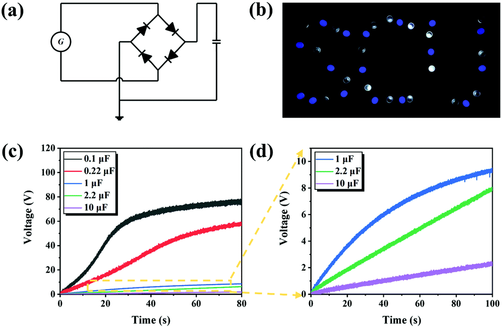 | ||
| Fig. 5 Applications of the Ag@SiO2–PEO-50 wt%/Ecoflex TENG with dimensions of 2 cm × 2 cm at a frequency of 3 Hz: (a) schematic diagram of the standard circuit for the TENG. (b) Letter pattern composed of LEDs (working voltage: 3.0–3.4 V) directly powered by the TENG via the standard circuit. (c) Comparative charge curves for aluminum electrolytic capacitors with different capacitances powered by the TENG by the standard circuit. (d) Enlarged view of the comparative charge curves. | ||
3.6. Sustainable utilization
The biocompatibility and water solubility of PEO material provide the possibility for the recycling of the Ag@SiO2 particles and the reutilization of the TENGs, which meets the current demands of ecological environment protection and sustainable development. The feasibility of the recycling of Ag@SiO2 particles was consequently evaluated, as shown in Fig. 6a. First, the Ag@SiO2–PEO-50 wt% film was immersed in deionized water. The PEO matrix dissolved gradually in the water, and then the Ag@SiO2 particles in the composite films settled at the bottom of the beaker by centrifugal separation. Ultimately, the residual particles could be obtained by a facile method of suction filtration and had a similar morphology as the original particles, as shown in Fig. 6b. The recycled particles could be uniformly mixed with the PEO aqueous solutions again to prepare the Ag@SiO2/PEO composite films as a positive material. Significantly, the recycling of the Ag@SiO2 particles did not have an appreciable effect on the output performance of the TENGs (Fig. 6c). Taken together, the results demonstrate that the viability of the sustainable utilization of the TENGs.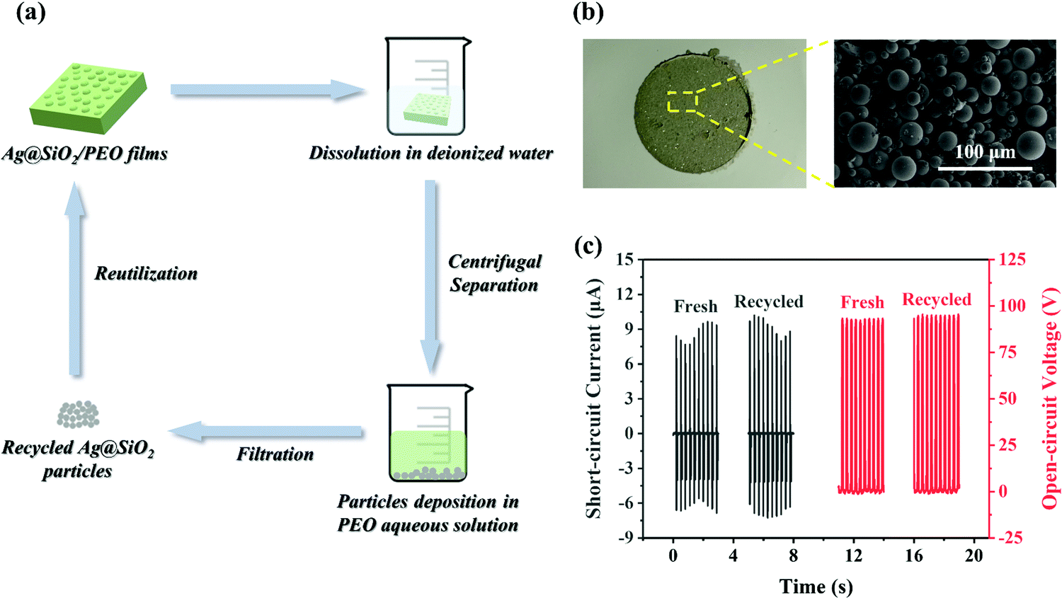 | ||
| Fig. 6 (a) Schematic diagram of the recycling process of the Ag@SiO2 particles. (b) Physical picture and SEM images of the recycled Ag@SiO2 particles. (c) Output performance of the fresh and recycled TENGs, in which the particles content was controlled at 50 wt%. | ||
4. Conclusion
In conclusion, environmentally friendly and sustainable PEO-based TENGs were successfully prepared with the introduction of the Ag@SiO2 particles by feasible solution casting. It was found that the output performance of the TENGs was effectively improved with the increase in the Ag@SiO2 particles content. When the Ag@SiO2 particles content reached 50 wt%, the short-circuit current, the open-circuit voltage and the transfer charges of the Ag@SiO2–PEO-50 wt%/Ecoflex TENG were about 10 μA, 95 V and 35 nC, respectively, which were 2.0, 1.8, and 2.1 times higher than that of the pristine PEO/Ecoflex TENG. The Ag@SiO2–PEO-50 wt%/Ecoflex TENG produced an output power density of 1.5 W m−2 at an external load of about 10 MΩ, which could be exploited for applications to power low-energy-consumption devices. The improvement of the output performance of the TENGs was mainly attributed to the synergistic effect of the enhancement of the surface roughness and the dielectric properties of the composite films. Additionally, the stability and flexibility of the Ag@SiO2/PEO films were proved by the cyclic measurements and the tensile stress–strain tests, respectively, which opens new developments in various areas of application in wearable electronic devices. Further, the practicability of the sustainable utilization of the TENGs was demonstrated owing to the water solubility of the PEO matrix. It is worth noting that the recycled TENG showed excellent performance stability, compared with the fresh sample. The environmentally friendly and sustainable Ag@SiO2–PEO/Ecoflex TENGs are not only suitable for self-powered systems for efficient energy collection and storage, but also have promising future prospects for biocompatible applications in wearable-flexible electronic devices.Author contributions
Xu Liu: methodology, formal analysis, investigation, data curation, writing-original draft, writing-review & editing, visualization. Xiao-Rong Sun: resources, visualization, project administration. Chen Luo: resources. Hong-Zhi Ma: resources. Hua Yu: resources. Yan Shao: conceptualization, methodology, writing-review & editing, project administration. Ming-Bo Yang: funding acquisition. Bo Yin: conceptualization, writing-review & editing, supervision, project administration, funding acquisition.Conflicts of interest
There are no conflicts of interest to declare.Acknowledgements
This work was supported by Sichuan Science and Technology Program (2020YFH0042), and financially supported by State Key Laboratory of Polymer Materials Engineering of Sichuan University (Grant No.: sklpme2019-2-16).References
- Z. L. Wang, ACS Nano, 2013, 7, 9533–9557 CrossRef CAS.
- Z. L. Wang, G. Zhu, Y. Yang, S. H. Wang and C. F. Pan, Mater. Today, 2012, 15, 532–543 CrossRef CAS.
- Y. Zhang, X. Lingling, Z. Liu, X. Cui, Z. Xiang, J. Bai, D. Jiang, J. Xue, C. Wang, Y. Lin, Z. Li, Y. Shan, Y. Yang, L. Bo, Z. Li and X. Zhou, Nano Energy, 2021, 85, 106009 CrossRef.
- R. Y. Liu, X. Kuang, J. N. Deng, Y. C. Wang, A. C. Wang, W. B. Ding, Y. C. Lai, J. Chen, P. H. Wang, Z. Q. Lin, H. J. Qi, B. Q. Sun and Z. L. Wang, Adv. Mater., 2018, 30, 1705195 CrossRef.
- C. R. Liu, Y. S. Wang, N. Zhang, X. Yang, Z. K. Wang, L. B. Zhao, W. H. Yang, L. X. Dong, L. F. Che, G. F. Wang and X. F. Zhou, Nano Energy, 2020, 67, 104228 CrossRef CAS.
- X. He, Y. L. Zi, H. Y. Guo, H. W. Zheng, Y. Xi, C. S. Wu, J. Wang, W. Zhang, C. H. Lu and Z. L. Wang, Adv. Funct. Mater., 2017, 27, 1604378 CrossRef.
- L. Shi, S. R. Dong, P. Ding, J. K. Chen, S. T. Liu, S. Y. Huang, H. S. Xu, U. Farooq, S. M. Zhang, S. J. Li and J. K. Luo, Nano Energy, 2019, 55, 548–557 CrossRef CAS.
- X. S. Zhang, M. D. Han, R. X. Wang, F. Y. Zhu, Z. H. Li, W. Wang and H. X. Zhang, Nano Lett., 2013, 13, 1168–1172 CrossRef CAS.
- L. Gu, L. German, T. Li, J. Li, Y. Shao, Y. Long, J. Y. Wang and X. D. Wang, ACS Appl. Mater. Interfaces, 2021, 13, 5133–5141 CrossRef CAS PubMed.
- A. Chandrasekhar, N. R. Alluri, V. Vivekananthan, Y. Purusothaman and S. J. Kim, J. Mater. Chem. C, 2017, 5, 1488–1493 RSC.
- C. K. Jeong, K. M. Baek, S. M. Niu, T. W. Nam, Y. H. Hur, D. Y. Park, G. T. Hwang, M. Byun, Z. L. Wang, Y. S. Jung and K. J. Lee, Nano Lett., 2014, 14, 7031–7038 CrossRef CAS PubMed.
- H. M. Chen, L. Bai, T. Li, C. Zhao, J. S. Zhang, N. Zhang, G. F. Song, Q. Q. Gan and Y. Xu, Nano Energy, 2018, 46, 73–80 CrossRef CAS.
- X. D. Wang, H. L. Zhang, L. Dong, X. Han, W. M. Du, J. Y. Zhai, C. F. Pan and Z. L. Wang, Adv. Mater., 2016, 28, 2896–2903 CrossRef CAS PubMed.
- Y. H. Yu and X. D. Wang, Extreme Mech. Lett., 2016, 9, 514–530 CrossRef.
- C. C. Wang and C. Y. Chang, J. Mater. Chem. C, 2020, 8, 4542–4548 RSC.
- S. H. Wang, Y. N. Xie, S. M. Niu, L. Lin, C. Liu, Y. S. Zhou and Z. L. Wang, Adv. Mater., 2014, 26, 6720–6728 CrossRef CAS PubMed.
- Y. Jie, N. Wang, X. Cao, Y. Xu, T. Li, X. J. Zhang and Z. L. Wang, ACS Nano, 2015, 9, 8376–8383 CrossRef CAS PubMed.
- Y. Shao, C. P. Feng, B. W. Deng, B. Yin and M. B. Yang, Nano Energy, 2019, 62, 620–627 CrossRef CAS.
- G. Zhu, Z. H. Lin, Q. S. Jing, P. Bai, C. F. Pan, Y. Yang, Y. S. Zhou and Z. L. Wang, Nano Lett., 2013, 13, 847–853 CrossRef CAS.
- L. X. Gao, D. L. Hu, M. K. Qi, J. Gong, H. Zhou, X. Chen, J. F. Chen, J. Cai, L. K. Wu, N. Hu, Y. Yang and X. J. Mu, Nanoscale, 2018, 10, 19781–19790 RSC.
- Z. Z. He, X. Yu, J. H. Yang, N. Zhang, T. Huang, Y. Wang and Z. W. Zhou, Composites, Part A, 2018, 104, 89–100 CrossRef CAS.
- S. Salaeh, G. Boiteux, P. Cassagnau and C. Nakason, Composites, Part A, 2017, 93, 107–116 CrossRef CAS.
- J. Kim, H. Ryu, J. H. Lee, U. Khan, S. S. Kwak, H. J. Yoon and S. W. Kim, Adv. Energy Mater., 2020, 10, 1903524 CrossRef CAS.
- X. Huang, L. Xie, Z. Hu and P. Jiang, IEEE Trans. Dielectr. Electr. Insul., 2011, 18, 375–383 CAS.
- R. Y. Zhang, M. Hummelgard, J. Ortegren, M. Olsen, H. Andersson and H. Olin, Nano Energy, 2019, 57, 279–292 CrossRef CAS.
- Y. M. Liu, J. L. Liu and L. F. Che, Sensors, 2021, 21, 2951 CrossRef CAS PubMed.
- X. Y. Li, J. Tao, X. D. Wang, J. Zhu, C. F. Pan and Z. L. Wang, Adv. Energy Mater., 2018, 8, 1800705 CrossRef.
- Y. J. Zou, J. Xu, K. Chen and J. Chen, Adv. Mater. Technol., 2021, 6, 2000916 CrossRef CAS.
- S. Pongampai, T. Charoonsuk, N. Pinpru, P. Pulphol, W. Vittayakorn, P. Pakawanit and N. Vittayakorn, Composites, Part B, 2021, 208, 108602 CrossRef CAS.
- F. Hu, Q. Cai, F. Liao, M. W. Shao and S. T. Lee, Small, 2015, 11, 5611–5628 CrossRef CAS.
- S. Chen, T. Huang, H. Zuo, S. H. Qian, Y. F. Guo, L. J. Sun, D. Lei, Q. L. Wu, B. Zhu, C. L. He, X. M. Mo, E. Jeffries, H. Yu and Z. W. You, Adv. Funct. Mater., 2018, 28, 1805108 CrossRef.
- F. Peng, D. Liu, W. Zhao, G. Q. Zheng, Y. X. Ji, K. Dai, L. W. Mi, D. B. Zhang, C. T. Liu and C. Y. Shen, Nano Energy, 2019, 65, 104068 CrossRef CAS.
- C. H. Yao, A. Hernandez, Y. H. Yu, Z. Y. Cai and X. D. Wang, Nano Energy, 2016, 30, 103–108 CrossRef CAS.
- Y. F. Guo, S. Chen, L. J. Sun, L. Yang, L. Z. Zhang, J. M. Lou and Z. W. You, Adv. Funct. Mater., 2021, 31, 2009799 CrossRef CAS.
- A. Chandrasekhar, N. R. Alluri, B. Saravanakumar, S. Selvarajan and S. J. Kim, J. Mater. Chem. C, 2017, 5, 1810–1815 RSC.
- H. Y. Mi, X. Jing, M. A. B. Meador, H. Q. Guo, L. S. Turng and S. Q. Gong, ACS Appl. Mater. Interfaces, 2018, 10, 30596–30606 CrossRef CAS.
- Y. L. Ren, G. X. Liu, H. Yang, T. Tong, S. H. Xu, L. Zhang, J. B. Luo, C. Zhang and G. X. Xie, Nano Energy, 2020, 68, 104303 CrossRef CAS.
- D. Z. Wang, Y. Lin, D. W. Hu, P. K. Jiang and X. Y. Huang, Composites, Part A, 2020, 130, 105754 CrossRef CAS.
- P. Ding, J. K. Chen, U. Farooq, P. F. Zhao, N. Soin, L. Y. Yu, H. Jin, X. Z. Wang, S. R. Dong and J. K. Luo, Nano Energy, 2018, 46, 63–72 CrossRef CAS.
- B. Z. Yang, Y. S. Lin and J. M. Wu, Appl. Mater. Today, 2017, 9, 96–103 CrossRef.
- Y. Zou, J. W. Liao, H. Ouyang, D. J. Jiang, C. C. Zhao, Z. Li, X. C. Qu, Z. Liu, Y. B. Fan, B. J. Shi, L. Zheng and Z. Li, Appl. Mater. Today, 2020, 20, 100699 CrossRef.
- X. Jing, H. Li, H. Y. Mi, P. Y. Feng, X. M. Tao, Y. J. Liu, C. T. Liu and C. Y. Shen, J. Mater. Chem. C, 2020, 8, 5752–5760 RSC.
- G. Lingxiao, C. Xin, W. Fayang, T. Daqiao, H. Xianming and M. Xiaojing, 2021 IEEE 34th International Conference on Micro Electro Mechanical Systems (MEMS), 2021, 238–241.
- A. H. Chen, C. Zhang, G. Zhu and Z. L. Wang, Adv. Sci., 2020, 7, 2000186 CrossRef CAS.
- J. M. Wu, C. K. Chang and Y. T. Chang, Nano Energy, 2016, 19, 39–47 CrossRef CAS.
- Z. H. Wang, S. M. Sun, N. Li, T. Yao and D. L. Lv, IEEE Access, 2020, 8, 172076 Search PubMed.
- Z. Zhou, H. Wang, Z. C. Zhu, H. Yang and Q. L. Zhang, Colloids Surf., A, 2019, 563, 59–67 CrossRef CAS.
- G. Jian, M. R. Liu, C. Yan, F. Wu, B. Song, K. S. Moon and C. P. Wong, Nano Energy, 2019, 58, 419–426 CrossRef CAS.
- D. Yang, M. Tian, W. C. Wang, D. D. Li, R. Y. Li, H. L. Liu and L. Q. Zhang, Electrochim. Acta, 2013, 87, 9–17 CrossRef CAS.
- J. W. Lee, H. J. Cho, J. Chun, K. N. Kim, S. Kim, C. W. Ahn, I. W. Kim, J. Y. Kim, S. W. Kim, C. Yang and J. M. Baik, Sci. Adv., 2017, 3, e1602902 CrossRef.
- S. M. Niu, S. H. Wang, L. Lin, Y. Liu, Y. S. Zhou, Y. F. Hu and Z. L. Wang, Energy Environ. Sci., 2013, 6, 3576–3583 RSC.
- Z. M. Dang, M. S. Zheng and J. W. Zha, Small, 2016, 12, 1688–1701 CrossRef CAS PubMed.
- R. Pethig, Biomicrofluidics, 2010, 4, 022811 CrossRef.
- G. Zhu, C. F. Pan, W. X. Guo, C. Y. Chen, Y. S. Zhou, R. M. Yu and Z. L. Wang, Nano Lett., 2012, 12, 4960–4965 CrossRef CAS PubMed.
Footnote |
| † Electronic supplementary information (ESI) available. See DOI: 10.1039/d1tc04831g |
| This journal is © The Royal Society of Chemistry 2022 |