
FeCo alloy nanoparticle decorated cellulose based carbon aerogel as a low-cost and efficient electromagnetic microwave absorber†
Yan
Guo
a,
Dedong
Wang
a,
Yu
Tian
a,
Jingwen
Wang
a,
Tiantian
Bai
a,
Hu
Liu
 *a,
Zhanhu
Guo
b,
Chuntai
Liu
*a and
Changyu
Shen
a
*a,
Zhanhu
Guo
b,
Chuntai
Liu
*a and
Changyu
Shen
a
aKey Laboratory of Materials Processing and Mold (Zhengzhou University), Ministry of Education, National Engineering Research Center for Advanced Polymer Processing Technology, Zhengzhou University, Zhengzhou, Henan 450002, China. E-mail: liuhu@zzu.edu.cn; ctliu@zzu.edu.cn
bIntegrated Composites Laboratory (ICL), Department of Chemical & Biomolecular Engineering, University of Tennessee, Knoxville, Tennessee 37996, USA
First published on 19th November 2021
Abstract
Recently, low-cost biomass based carbon aerogels have turned out to be promising efficient electromagnetic wave (EMW) absorption materials, but the bad impedance matching and single loss mechanism often result in poor EMW absorption properties. In this study, magnetic FeCo alloy nanoparticle decorated cellulose-based carbon aerogel (FeCo@CCA) was prepared by calcining the cellulose aerogel with homogeneously dispersed CoFe2O4 particles (CoFe2O4@CA), which was the freeze-dried product of hydrothermal treated Fe2+/Co2+ metal ion absorbed cellulose hydrogel. Here, the hydrothermal synthesis method can effectively ensure the even dispersion of the calcination product of magnetic FeCo alloy nanoparticles, which is conducive to good impedance matching, additional magnetic loss, and improved dielectric loss. Besides, the porous structure of the aerogel can also result in multi-reflection/scattering to attenuate more the incident EMW. As a result, the EMW absorption properties of the prepared FeCo@CCA can be effectively tuned by changing the metal ion concentration, and the product arising from a metal ion concentration of 100 mmol L−1 (FeCo@CCA-100) displays the strongest EWM absorption capacity with a minimum reflection loss (RLmin) of −49.5 dB at a thickness of 4.05 mm at 9.84 GHz and a maximum effective absorption bandwidth (EABmax, RL < −10 dB) of 10.88 GHz (6.96–17.84 GHz), covering the whole Ku and X band and almost half of the C band. This study provides a guideline for developing efficient cellulose-based carbon aerogel based EMW absorbers.
1. Introduction
With the consistent development of electronic devices and communication technology in the field of civilian and scientific research, the increasingly serious electromagnetic wave (EMW) irradiation and interference have become a severe pollution hazard, which greatly affects the human biological system, the normal operation of electrical equipment, and information security.1–3 Some high-performance electromagnetic shielding materials have been developed to solve these problems,4,5 but they can often cause secondary electromagnetic pollution. Thus, exploring highly efficient EMW absorption materials, which can effectively absorb and dissipate the incident EMW by converting electromagnetic energy into thermal energy or other energy forms,6 turns out to be an effective measure to alleviate or eliminate the detrimental effect of EMW pollution on the environment and humans. Meanwhile, researchers are always committed to preparing EMW absorbers with thin matching thickness, light weight, wide absorbing bandwidth, and strong absorption capability to satisfy different practical applications.7–9Carbon-based materials have been widely applied as EMW absorbers based on their features of high electrical conductivity, light weight, good physicochemical stability, low density, and adjustable dielectric properties,10,11 and these include graphene,12 carbon nanotubes,13 biomass-based carbon,14 and carbon fibers.15 However, their excessive electrical conductivity can often lead to undesired reflection of the incident EMW due to the bad impedance matching between carbon and free air.16 To solve this problem, carbon-based aerogels with the merits of a special three dimensional structure, high porosity, low density, lightweight, and large specific surface area have attracted increasing attention in the preparation of EMW absorption materials,17,18 where the high-volume fraction of air can also availably optimize the impedance matching, ensuring that more EMW can enter into the interior of carbon aerogels.3,18 Besides, plentiful air/carbon framework interfaces inside the cellulose aerogels can also boost the EMW attenuation by strong dielectric relaxation and interfacial polarization.18 More importantly, the special three-dimensional (3D) structure can greatly enhance the EMW absorption performance through the multi-reflection/scattering between adjacent cell walls that generates more inner transmission channels. For example, Bai et al. successfully fabricated a resilient and lightweight bacterial cellulose derived C/rGO aerogel via the unidirectional freeze-drying and pyrolysis techniques, which showed an outstanding EMW absorption performance with a RLmin of −46.11 dB and a broad EAB of 9.12 GHz due to the porous 3D structure.3 Furthermore, the combination of magnetic materials and carbon materials that can optimize the impedance matching and provide additional magnetic loss capacity simultaneously was identified as another effective design strategy to achieve highly efficient EMW absorption of carbon materials. Meanwhile, the abundant heterogeneous interfaces between magnetic particles and carbon materials can also result in great interfacial polarization loss towards the incident EMW, attenuating more electromagnetic energy. For instance, Tan et al. have synthesized FeCo/C microspheres using a two-step hydrothermal method, which exhibit a RLmin of −51.36 dB at 2.6 mm with the corresponding EAB at 4.3 GHz.7 However, the homogeneous dispersion of magnetic materials is a critical factor that needs to be considered to achieve the stated synergistic effect.
Herein, magnetic FeCo alloy nanoparticle decorated low-cost cellulose-based carbon aerogel (FeCo@CCA) was prepared by calcining the cellulose aerogel with homogeneously dispersed CoFe2O4 particles (CoFe2O4@CA), which was the freeze-dried product of hydrothermal treated Fe2+/Co2+ metal ion absorbed cellulose hydrogel. Here, the hydrothermal synthesis method was applied to achieve the even dispersion of the calcination product of magnetic FeCo alloy nanoparticles. Subsequently, a series of FeCo@CCA with different magnetic particle loading were fabricated by changing the metal ion concentration, and their morphological, structural, and magnetic properties were systematically investigated using SEM, XRD, and VSM, respectively. Finally, the contrastive study of the EMW absorption capability of different FeCo@CCA samples was conducted, and the product arising from a metal ion concentration of 100 mmol L−1 (FeCo@CCA-100) was found to exhibit superior EMW absorption performance with a RLmin value of −49.5 dB at a thickness of 4.05 mm at 9.84 GHz, and a wide EAB of 10.88 GHz (from 6.96 to 17.84 GHz). This study provides new guidance for the fabrication of cellulose-based aerogels for efficient EMW absorption applications.
2. Experimental section
2.1. Materials and chemicals
The α-cellulose with a length of 25 mm was purchased from Shanghai Aladdin Biochemical Technology Co., Ltd, China. Sodium hydroxide (NaOH), urea, epichlorohydrin (ECH), ferrous sulfate (FeSO4·7H2O), and cobaltous chloride (CoCl2) were supplied by Tianjin Damao Chemical Reagent Factory, China. Potassium nitrate (KNO3) was purchased from Tianjin Kemiou Chemical Reagent Co., Ltd, China. All the materials and chemicals were used as received without further treatment.2.2. Preparation of CH
Typically, 4 g of cellulose was first dispersed in 100 g NaOH/urea aqueous solution (mass ratio of NaOH/urea/deionized (DI) water = 7/12/81) and precooled to −12 °C in a refrigerator for 12 h, and then mechanically stirred for 30 min to dissolve the cellulose completely. After mixing with 10 mL of ECH uniformly under vigorous stirring for 10 min and well degassed, the resultant solution was poured into a glass tube (inner diameter = 19 mm), cross-linked at 50 °C for 8 h, and aged at room temperature for 48 h. Cellulose hydrogel (CH) was obtained after soaking the resultant gel in DI water which was changed at 10 h intervals to remove the remnant NaOH/urea component completely until the pH value reached 7.2.3. Preparation of FeCo@CCA
FeCo@CA was prepared using the hydrothermal plus pyrolysis method. Firstly, the as-prepared CH was immersed in 100 mL of FeSO4/CoCl2 aqueous solution (mole ratio of Fe2+/Co2+ = 2![[thin space (1/6-em)]](https://www.rsc.org/images/entities/char_2009.gif) :1) with a certain concentration for 8 h and then maintained at 90 °C for 3 h. Subsequently, CH was transferred to 200 mL of NaOH (1.32 mol dm−3)/KNO3 (mole ratio of Fe2+/NO−3 = 0.44) aqueous solution and kept at 90 °C for 6 h, and was then immersed in DI water to remove the redundant metal ions to acquire CoFe2O4@CH. Then, CoFe2O4@CH was frozen at −25 °C for 72 h and freeze-dried (−80 °C, 20 Pa) for 72 h to obtain CoFe2O4@CA. Finally, the resultant CoFe2O4@CA was calcined in a tube furnace at 580 °C (heating rate: 5 °C min−1) for 2 h in a N2 atmosphere (flow rate of 100 mL min−1), and the final calcination products were named FeCo@CCA. In this study, a series of FeCo@CA were prepared by changing the concentration of FeSO4/CoCl2 aqueous solution and were denoted as CoFe2O4@CA-x and FeCo@CCA-x, where x represents 50, 100, and 150 mmol L−1, respectively.
:1) with a certain concentration for 8 h and then maintained at 90 °C for 3 h. Subsequently, CH was transferred to 200 mL of NaOH (1.32 mol dm−3)/KNO3 (mole ratio of Fe2+/NO−3 = 0.44) aqueous solution and kept at 90 °C for 6 h, and was then immersed in DI water to remove the redundant metal ions to acquire CoFe2O4@CH. Then, CoFe2O4@CH was frozen at −25 °C for 72 h and freeze-dried (−80 °C, 20 Pa) for 72 h to obtain CoFe2O4@CA. Finally, the resultant CoFe2O4@CA was calcined in a tube furnace at 580 °C (heating rate: 5 °C min−1) for 2 h in a N2 atmosphere (flow rate of 100 mL min−1), and the final calcination products were named FeCo@CCA. In this study, a series of FeCo@CA were prepared by changing the concentration of FeSO4/CoCl2 aqueous solution and were denoted as CoFe2O4@CA-x and FeCo@CCA-x, where x represents 50, 100, and 150 mmol L−1, respectively.
2.4. Characterization
X-Ray diffraction (XRD) spectra in the range of 10–90° were collected on a Bruker D8 Discover diffractometer with a Cu tube to study the crystalline structure of the sample. The morphology of the sample was examined using a Zeiss Supra 55 field-emission scanning electron microscope (SEM) system under an accelerating voltage of 5 kV. A vibrating sample magnetometer (VSM, YPC7-VSM-130) was used to study the magnetization hysteresis curve of the sample at room temperature. The sample was impregnated with molten paraffin wax through the vacuum infusion process and cut into a coaxial torus (Φouter = 7.00 mm, Φinner = 3.04 mm, thickness = 2.00 mm) for EMW absorption testing, and the sample loading was fixed to be about 20 wt%. The relative permittivity and permeability of the sample were measured using a Keysight N5222B vector network analyzer in the frequency range of 2–18 GHz via the coaxial-line method for the calculation of reflection loss (RL).3. Results and discussion
As shown in Fig. 1, FeCo@CCA is prepared using the hydrothermal plus pyrolysis method, and the details are described in the experimental section. Specifically, the regenerated transparent CH (Fig. 1b) is first immersed in the FeSO4/CoCl2 aqueous solution for 8 h, and the Fe2+/Co2+ metal ions are expected to be absorbed on the hydrogel network through coordination bonds with the rich hydroxyl groups of cellulose. Then, the Fe2+/Co2+ absorbed hydrogel is heated at 90 °C for 6 h to generate the corresponding non-magnetic metal hydroxide/oxide nanoparticles, which are further converted into magnetic CoFe2O4 nanoparticles through heating in NaOH/KNO3 aqueous solution at 90 °C. Meanwhile, as shown in Fig. 1c, the color of the resultant hydrogel changes into dark brown, indicating that the CoFe2O4 nanoparticles are successfully generated in the hydrogel. Furthermore, the obtained CoFe2O4@CH is freeze-dried into brown lightweight CoFe2O4@CA that can stand on the dogtail grass steadily (Fig. 1d). Finally, pyrolysis is conducted to enable the carbonization of cellulose aerogel into cellulose-based carbon aerogel and the reduction of CoFe2O4 into FeCo alloy simultaneously, resulting in a significant volume shrinkage of the resultant black magnetic FeCo@CCA (Fig. 1e).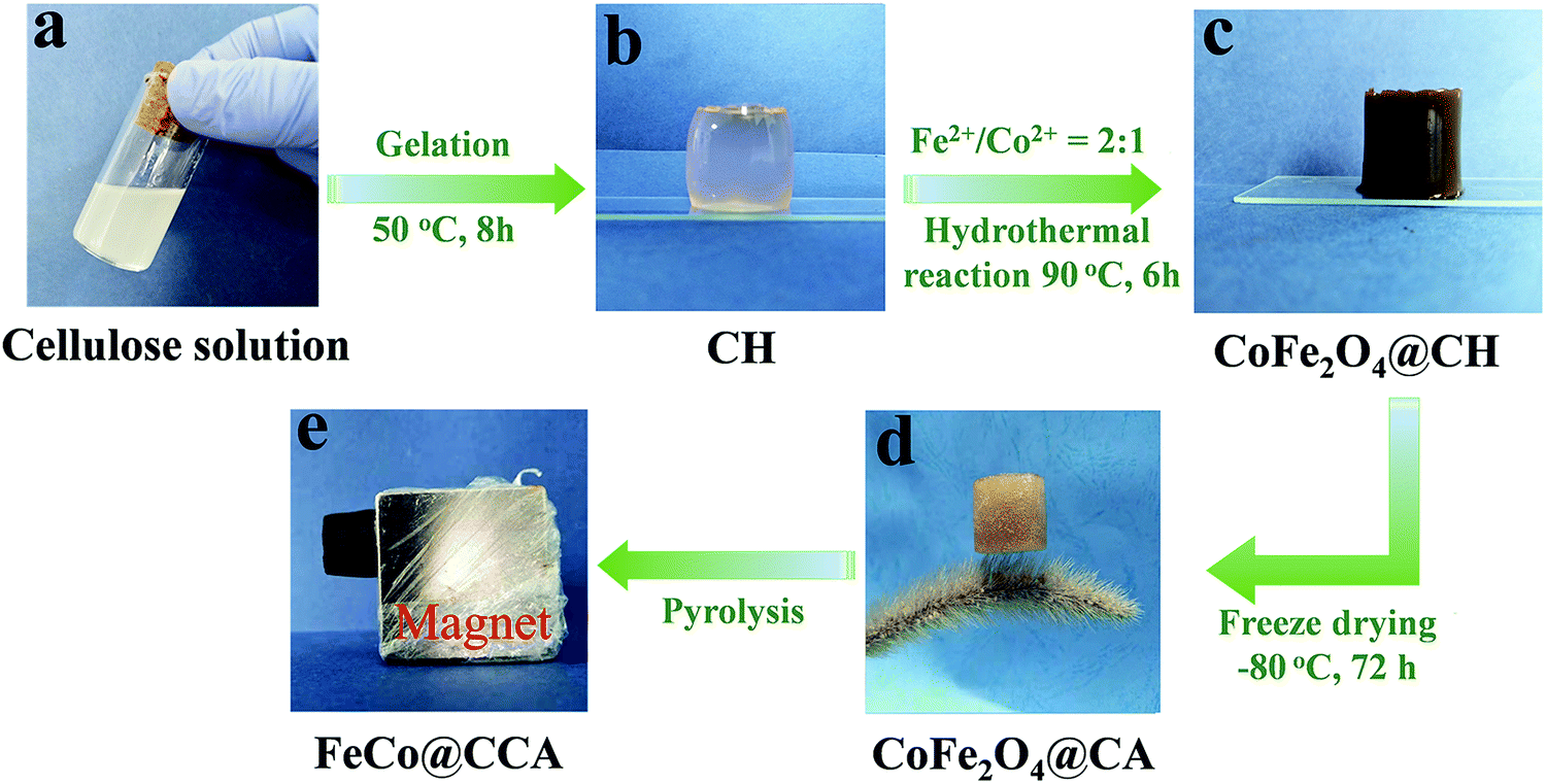 | ||
| Fig. 1 Schematic illustration showing the preparation process of FeCo@CCA. | ||
The detailed microscopic morphology of the samples was characterized by SEM. As shown in Fig. 2a, CoFe2O4@CA presents an open cellular structure with an average diameter of 298 μm arising from the sublimation of ice crystals during the freeze-drying process, which is well maintained for the calcined product of CoFe@CCA (Fig. 2d). But the average cell diameter displays a significant reduction to 55 μm due to the combustion of the cellulose matrix. With a more magnified view, CoFe2O4 nanoparticles with an average diameter of 393 nm are also converted into FeCo nanoparticles with an average diameter of 112 nm, which are homogeneously dispersed in the aerogel skeleton (Fig. 2b and e) and on the surface of the cell wall (Fig. 2c and f), demonstrating the high efficiency of our synthetic method. Importantly, as presented in Fig. S1 (ESI†), our prepared CoFe@CCA shows the typical metal ion concentration dependent porous structure, where the average cell diameter exhibits an increasing trend and the FeCo nanoparticle diameter also tends to be greater with increasing metal ion concentration. All these can be explained by the fact that higher metal ion absorbed hydrogel can lead to larger FeCo aggregation, which can effectively restrain the shrinkage of the cellulose skeleton during the calcination process. Herein, it can be claimed that the morphology and structure of the fabricated FeCo@CCA can be effectively controlled by adjusting the mole concentration of FeSO4/CoCl2 aqueous solution.
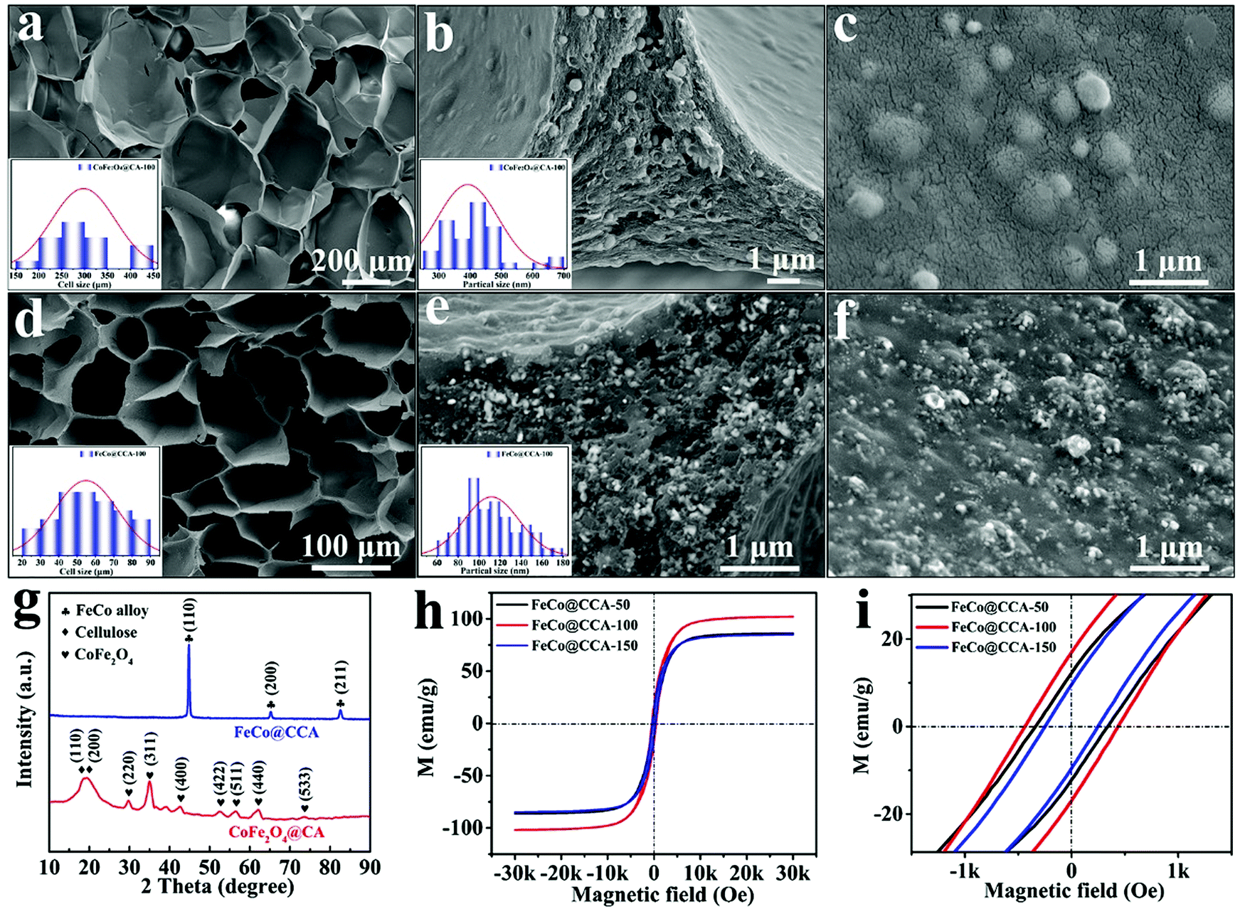 | ||
| Fig. 2 SEM images of (a–c) CoFe2O4@CA-100 and (d–f) FeCo@CCA-100. (g) XRD patterns of CoFe2O4@CA-100 and FeCo@CCA-100. (h, i) Room temperature magnetic hysteresis loops of FeCo@CCA-50, FeCo@CCA-100, and FeCo@CCA-150. | ||
In order to confirm the components of the synthesized samples, XRD patterns of CoFe2O4@CA and FeCo@CCA were collected and are shown in Fig. 2g. Clearly, CoFe2O4@CA displays two diffraction peaks located at 18.8° and 19.4°, which are ascribed to the (110) and (200) crystal planes of cellulose.19,20 In addition, the diffraction peaks at 29.7° (220), 35.0° (311), 42.6° (400), 52.6° (422), 56.5° (511), 62.1° (440), and 73.7° (533) are typical for the face-centered cubic phase of CoFe2O4 (JCPDF #22-1086),21–23 demonstrating the well crystalline nature of CoFe2O4. After calcination, all the typical diffraction peaks of cellulose and CoFe2O4 disappear, and some new sharp characteristic peaks at 44.8°, 65.2° and 82.6° corresponding to the (110), (200), and (211) planes of the cubic crystal structure of FeCo nanoparticles (JCPDS #49-1568) are well observed, indicating the highly crystalline nature of the generated FeCo particles.24,25
Room temperature magnetic properties of different FeCo@CCA samples were also tested by VSM at room temperature. It is well known that the magnetic properties of materials are greatly dependent on their shape, structure, and size. As displayed in Fig. 2h, all the samples display typical ferromagnetic S-shaped hysteresis loops, and the saturation magnetization (MS) of FeCo@CCA-50, FeCo@CCA-100, and FeCo@CCA-150 is calculated to be 86, 102, and 85 emu g−1, respectively. Obviously, the reduction of CoFe2O4 into FeCo can effectively enhance the MS of all FeCo@CCA compared with that of CoFe2O4@CA (12 emu g−1, Fig. S2, ESI†).26 Meanwhile, the coercivity (HC) values of FeCo@CCA-50, FeCo@CCA-100, and FeCo@CCA-150 are 340.1, 437.5, and 248.0 Oe, respectively (Fig. 2i). Obviously, FeCo@CCA-100 exhibits larger MS and HC than those of FeCo@CCA-50 but smaller than those of FeCo@CCA-150. All these can be well explained by the high metal ion concentration that leads to aggregated magnetic FeCo nanoparticles of increased diameter, resulting in decreased magnetic properties of the prepared FeCo@CCA. Notably, high MS and HC are beneficial for improving the high frequency resonance to enhance the EMW attenuation capacity.
Reflection loss (RL) is applied to evaluate the EMW absorption performances of the prepared FeCo@CCA. Based on the transmission line theory, the measured electromagnetic parameters are used to calculate the RL value of the sample using the following equations:27,28
| RL (dB) = 20log∣(Zin−Z0)/(Zin−Z0)∣ | (1) |
 | (2) |
EMA absorption performances of FeCo@CCA-50, FeCo@CCA-100, and FeCo@CCA-150 were systematically investigated. Obviously, as shown in Fig. 3a, the minimum RL (RLmin) value of FeCo@CCA-50 is only −6.5 dB, which cannot meet the basic engineering requirement of −10 dB. For FeCo@CCA-100 (Fig. 3b), its EMW absorption performance is significantly enhanced and the RLmin value reaches −49.5 dB at 9.84 GHz at 4.05 mm, indicating that about 99.999% EMW can be effectively attenuated. However, the RLmin value of FeCo@CCA-150 turns out to be −17.9 dB (Fig. 3c), showing a decreased EMW absorption performance. Hence, it can be claimed that the EMW absorption performance of the resultant FeCo@CCA is greatly affected by the FeCo magnetic particle loading. What's more, the 2D RL projection mappings of FeCo@CCA-100 were further analyzed (Fig. 3d), and the maximum EAB (EABmax) of FeCo@CCA-100 is as high as 10.88 GHz (6.96–17.84 GHz) at a thickness of 5.00 mm, covering the whole Ku and X band and part of the C band. As for RLmin and EABmax, as shown in Fig. 3e, our prepared FeCo@CCA presents broader EAB and stronger EMW absorption capacity compared with other reported works.19,29–37
 | ||
| Fig. 3 3D RL plots of (a) FeCo@CCA-50, (b) FeCo@CCA-100, and (c) FeCo@CCA-150. (d) 2D RL projection mappings of FeCo@CCA-100. (e) RLminversus EABmax of FeCo@CCA-100 and other reported works. | ||
Generally, EMW absorption performances are closely related with the complex permittivity (εr = ε′–jε′′) and complex permeability (μr = μ′−jμ′′). The real part of complex permittivity (ε′) and complex permeability (μ′) represents the storage capacity of microwave energy, while the imaginary part (ε′′ and μ′′) is related to the energy dissipation of microwave energy.1,38 As shown in Fig. 4a and b, both the ε′ and ε′′ curves of all samples exhibit a downward tendency with increasing frequency from 2 to 18 GHz. The typical frequency-dependent behavior of ε′ is mainly associated with the aggravated polarization lag of electric dipole caused by high-frequency electric field changes.39 Meanwhile, the ε′ and ε′′ values of different FeCo@CCA in the whole frequency range follow the order FeCo@CCA-50 < FeCo@CCA-100 < FeCo@CCA-150, indicating that higher ε′ and ε′′ values can be obtained for the FeCo@CCA with higher FeCo magnetic particle loading. Based on the dielectric loss theory, the conductive loss and polarization loss are the main factors that affect the permittivity. As for permeability, it can be seen from Fig. 4d and e that all the samples have similar values of μ′ and μ′′ in the whole frequency range, implying that the magnetic particle loading has a weak effect on the magnetic loss properties. But it is worth noting that the μ′′ curves of all samples display several resonant peaks in the whole frequency range, indicating the existence of exchange and natural resonance.40 Furthermore, the dielectric loss tangent (tanδε = ε′′/ε′) and the magnetic loss tangent (tanδμ = μ′′/μ′) which represent the dielectric and magnetic attenuation capacity were also studied. Clearly, the tanδε value of FeCo@CCA-50, FeCo@CCA-100, and FeCo@CCA-150 increases gradually (Fig. 4c), which can be ascribed to the increasing FeCo loading that results in more heterogeneous interface polarization loss and excessive conduction loss. For the tanδμ curves shown in Fig. 4f, the consistent pattern with μ′′ illustrates the contribution of magnetic resonance to magnetic loss. More importantly, the value of tanδε is much higher than the value of tanδμ for all samples, revealing that the dielectric loss is the determining factor in the loss mechanism of our prepared FeCo@CCA.
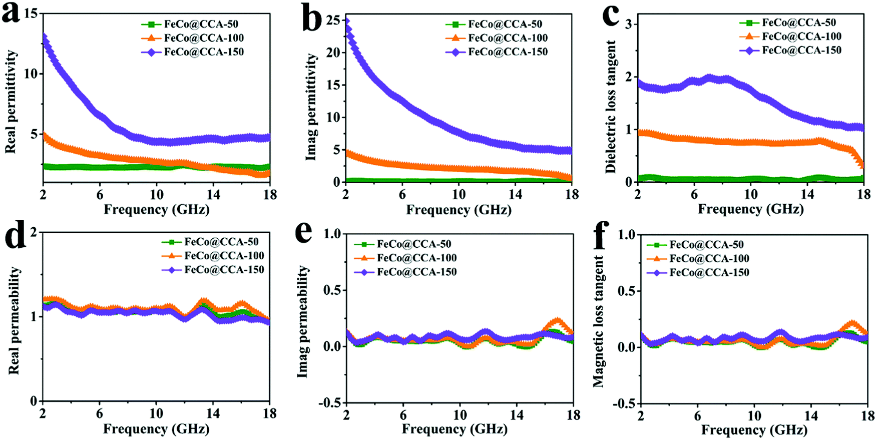 | ||
| Fig. 4 (a) Real parts of permittivity (ε′), (b) imaginary parts of permittivity (ε′′), (c) dielectric loss tangents (tanδε), (d) real parts of permeability (μ′), (e) imaginary parts of permeability (μ′′), and (f) magnetic loss tangents (tanδμ) of FeCo@CCA-50, FeCo@CCA-100, and FeCo@CCA-150. | ||
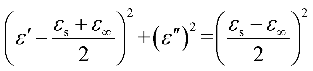
The dielectric loss behavior of the sample was further explored based on the Debye relaxation theory, where the relationship between ε′ and ε′′ can be described by the following formula:41
 | (3) |
| C0 = μ′′(μ′)−1f−1 = 2πμ0d2σ/3 | (4) |
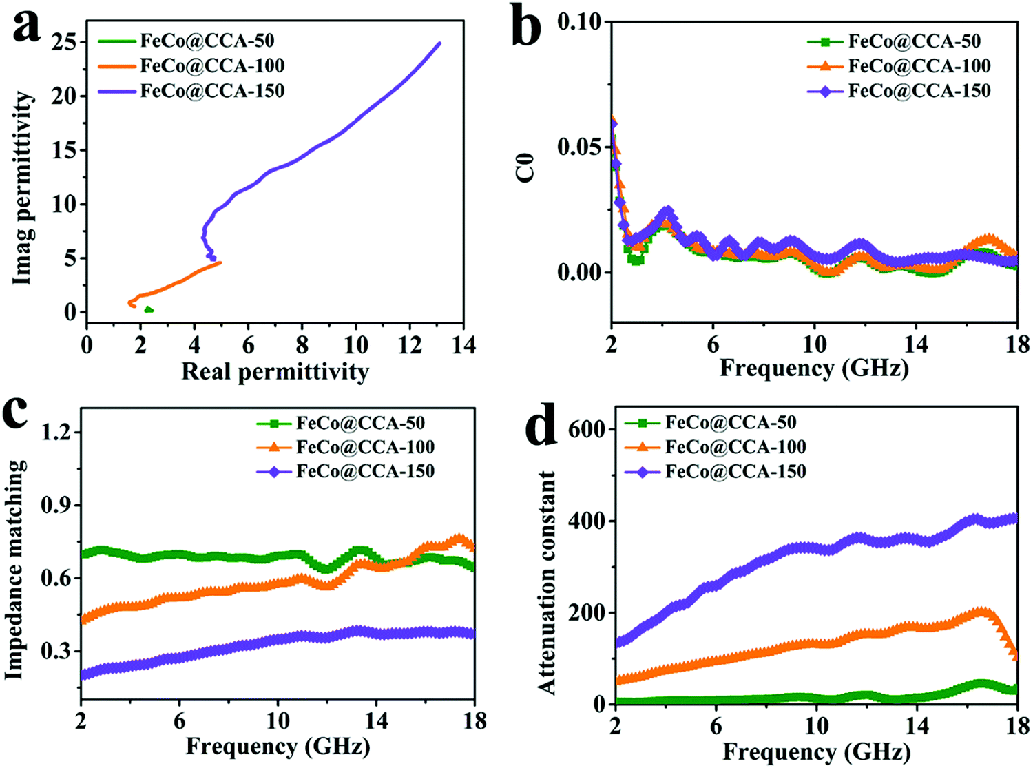 | ||
| Fig. 5 (a) Cole–Cole plots, (b) C0versus frequency curves, (c) impedance matching and (d) attenuation constants of FeCo@CCA-50, FeCo@CCA-100, and FeCo@CCA-150. | ||
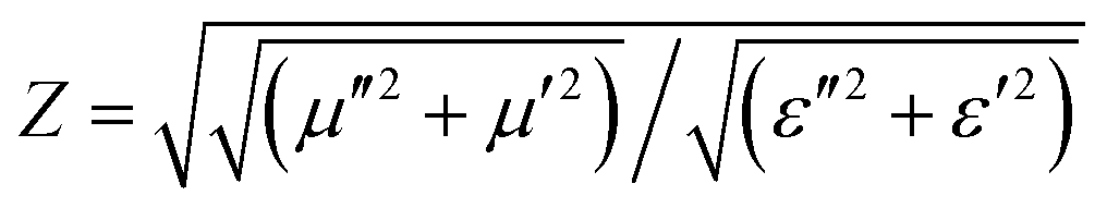
To achieve excellent EMW absorption performances, good impedance matching and strong EMW attenuation capacity are two important indicators. Impedance matching (Z) represents the ability of the incident EMW to enter the interior of the absorber, and is expressed by the following equation:36
 | (5) |
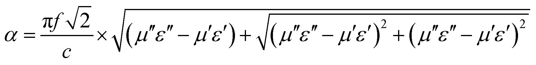
In general, a Z value equal to 1 indicates a good matching between materials and space medium which enables the incident EMW to penetrate into the absorber without being reflected on its surface. Fig. 5c shows that the Z value of FeCo@CCA-50 is close to 1, suggesting that this sample has a good impedance matching. However, the Z value tends to decrease with increasing magnetic particle loading, indicating a worse impedance matching that is unfavorable for the penetration of the EMW. In addition, the attenuation constant (α) is applied to evaluate the attenuation capacity of the absorber towards the incident EMW. α is expressed in detail as follows:42
 | (6) |
Based on the above analysis, the EMW absorption mechanism of the prepared FeCo@CCA is schematically shown in Fig. 6. When the EMW enters into the material, it will lead to the migration and hopping of electrons due to the existence of the carbon skeleton and FeCo alloy, resulting in conduction loss. Under the action of an electromagnetic field, the electrons accumulate at the heterogeneous FeCo/carbon interfaces to form powerful interfacial polarization. Meanwhile, dipolar polarization can also be induced by the pores, defects and abundant oxygen-containing functional groups. Furthermore, the eddy current effect, exchange resonance, and natural resonance occur due to the existence of magnetic FeCo nanoparticles. Finally, the porous structure is beneficial for the multiple reflection/scattering of the EMW inside the material, resulting in a prolonged propagation path and enhanced attenuation capacity. More importantly, the porous structure is also good to optimize impedance matching, enabling EMW to enter into the absorber as much as possible. In this work, magnetic nanoparticle loading is tuned to achieve a good balance between attenuation capacity and impedance matching, achieving the best EMW absorption performances.
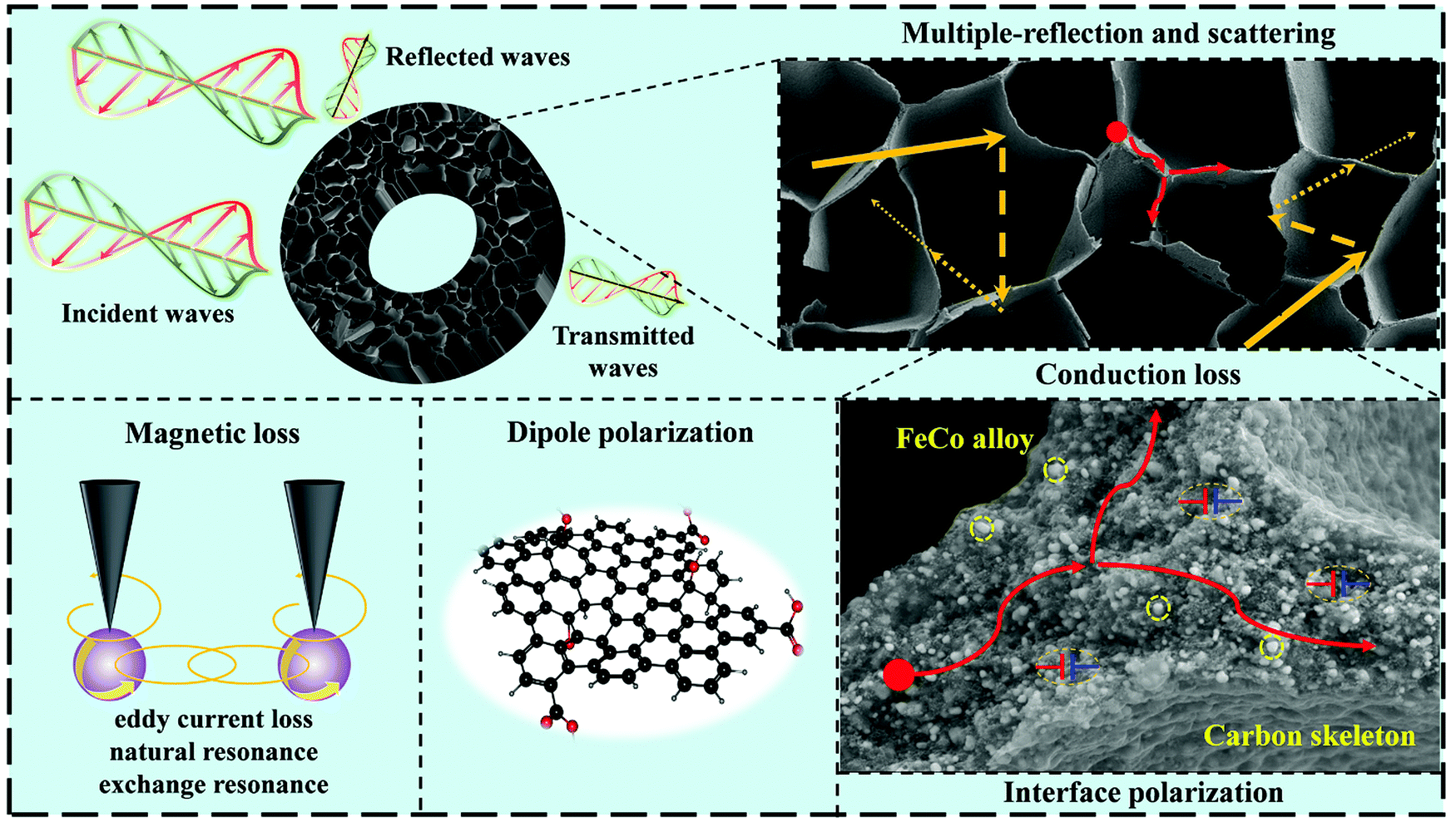 | ||
| Fig. 6 Schematic illustration showing the EMW absorption mechanism of our prepared FeCo@CCA. | ||
4. Conclusion
In summary, magnetic FeCo alloy nanoparticle decorated cellulose-based carbon aerogel (FeCo@CCA) was prepared by calcining the cellulose aerogel with homogeneously dispersed CoFe2O4 particles (CoFe2O4@CA), which was the freeze-dried product of hydrothermal treated Fe2+/Co2+ metal ion absorbed cellulose hydrogel. When used as an EMW absorber, in addition to the porous 3D structure of the material that can enhance the EMW capacity through the multiple reflection/scattering to dissipate more EMW, the co-existence of FeCo alloy nanoparticles and the carbon skeleton can lead to the dielectric-magnetic dual-loss mechanism towards the EMW, which is beneficial for better impedance matching and stronger attenuation ability compared with the single carbon materials. Besides, the abundant FeCo/carbon heterogeneous interfaces can also result in powerful polarization loss. Interestingly, the porous structure of the aerogel and the diameter of FeCo alloy nanoparticles were effectively tuned by changing the absorbed metal ion concentration, which affected the EMW absorption performance of our prepared FeCo@CCA significantly. As a result, FeCo@CCA-100 displays an outstanding EMW absorption capacity (RLmin = −49.5 dB) at 9.84 GHz with a thickness of 4.05 mm, and the EABmax covers 10.88 GHz (6.96–17.84 GHz). Undoubtedly, the fabrication of the FeCo@CCA sample is a low-cost and sustainable strategy for efficient EMW absorbers with lightweight, strong absorption performance and wide effective absorption bandwidth.Conflicts of interest
The authors declare no competing financial interests.Acknowledgements
The research was financially supported by the National Natural Science Foundation of China (No: 51803191 and 12072325), the National Key R&D Program of China (2019YFA0706802), the 111 project (D18023), and the Key Scientific and Technological Project of Henan Province (202102210038).References
- J. Pan, H. Yang, Q. Hong, H. M. Wen, J. Q. Xiao and J. Hu, J. Mater. Chem. C, 2021, 9, 7302–7309 RSC.
- J. Fang, P. Li, Y. Liu and Y. Min, J. Mater. Chem. C, 2021, 9, 2474–2482 RSC.
- (a) T. Bai, Y. Guo, D. Wang, H. Liu, G. Song, Y. Wang, Z. Guo, C. Liu and C. Shen, J. Mater. Chem. A, 2021, 9, 5566–5577 RSC; (b) Y. Guo, D. Wang, T. Bai, H. Liu, Y. Zheng, C. Liu and C. Shen, Adv. Compos. Hybrid Mater., 2021, 4, 602–613 CrossRef CAS.
- (a) L. Wang, X. T. Shi, J. L. Zhang, Y. L. Zhang and J. W. Gu, J. Mater. Sci. Technol., 2020, 52, 119–126 CrossRef; (b) P. Song, B. Liu, C. B. Liang, K. P. Ruan, H. Qiu, Z. L. Ma, Y. Q. Guo and J. W. Gu, Nano-Micro Lett., 2021, 13, 91 CrossRef CAS.
- (a) L. Wang, Z. L. Ma, Y. L. Zhang, L. X. Chen, D. P. Cao and J. W. Gu, SusMat, 2021, 1, 413–431 CrossRef; (b) X. T. Yang, S. G. Fan, Y. Li, Y. Q. Guo, Y. G. Li, K. P. Ruan, S. M. Zhang, J. L. Zhang, J. Kong and J. W. Gu, Composites, Part A, 2020, 128, 105670 CrossRef CAS; (c) F. Q. Qi, L. Wang, Y. L. Zhang, Z. L. Ma, H. Qiu and J. W. Gu, Mater. Today Phys., 2021, 21, 100512 CrossRef CAS.
- H. Yang, B. Wen and L. Wang, Appl. Surf. Sci., 2020, 509, 145336 CrossRef CAS.
- R. Tan, J. Zhou, Z. Yao, B. Wei, J. Zu, H. Lin and Z. Li, J. Alloys Compd., 2021, 857, 157568 CrossRef CAS.
- F. Wu, P. Liu, J. Wang, T. Shah, M. Ahmad, Q. Zhang and B. Zhang, J. Colloid Interface Sci., 2020, 577, 242–255 CrossRef CAS PubMed.
- Z. Xiang, C. Huang, Y. Song, B. Deng, X. Zhang, X. Zhu, D. Batalu, O. Tutunaru and W. Lu, Carbon, 2020, 167, 364–377 CrossRef CAS.
- N. Yang, Z. X. Luo, G. R. Zhu, S. C. Chen, X. L. Wang, G. Wu and Y. Z. Wang, ACS Appl. Mater. Interfaces, 2019, 11, 35987–35998 CrossRef CAS PubMed.
- X. Ye, Z. Chen, M. Li, T. Wang, C. Wu, J. Zhang, Q. Zhou, H. Liu and S. Cui, ACS Sustainable Chem. Eng., 2019, 7, 18395–18404 CrossRef CAS.
- C. Cui, R. Guo, E. Ren, H. Xiao, M. Zhou, X. Lai, Q. Qin, S. Jiang and W. Qin, Chem. Eng. J., 2021, 405, 126626 CrossRef CAS.
- W. Xue, G. Yang, S. Bi, J. Zhang and Z. L. Hou, Carbon, 2021, 173, 521–527 CrossRef CAS.
- S. Dong, P. Hu, X. Li, C. Hong, X. Zhang and J. Han, Chem. Eng. J., 2020, 398, 125588 CrossRef CAS.
- J. Chen, J. Zheng, F. Wang, Q. Huang and G. Ji, Carbon, 2021, 174, 509–517 CrossRef CAS.
- F. Chen, H. Luo, Y. Cheng, R. Guo, W. Yang, X. Wang and R. Gong, Composites, Part A, 2021, 140, 106141 CrossRef CAS.
- X. Ma, Y. Lou, X. B. Chen, Z. Shi and Y. Xu, Chem. Eng. J., 2019, 356, 227–235 CrossRef CAS.
- L. Liang, Z. Zhang, F. Song, W. Zhang, H. Li, J. Gu, Q. Liu and D. Zhang, Carbon, 2020, 162, 283–291 CrossRef CAS.
- Z. Zhang, J. Tan, W. Gu, H. Zhao, J. Zheng, B. Zhang and G. Ji, Chem. Eng. J., 2020, 395, 125190 CrossRef CAS.
- Y. Chen, P. Potschke, J. Pionteck, B. Voit and H. Qi, ACS Appl. Mater. Interfaces, 2020, 12, 22088–22098 CrossRef CAS PubMed.
- F. Ren, Z. Guo, Y. Shi, L. Jia, Y. Qing, P. Ren and D. Yan, J. Alloys Compd., 2018, 768, 6–14 CrossRef CAS.
- X. Cui, W. Liu, W. Gu, X. Liang and G. Ji, Inorg. Chem. Front., 2019, 6, 590–597 RSC.
- Z. Liu, C. Shi, F. He and N. Zhao, Integr. Ferroelectr., 2020, 208, 164–176 CrossRef CAS.
- H. Duan, H. Zhu, J. Gao, D. X. Yan, K. Dai, Y. Yang, G. Zhao, Y. Liu and Z. M. Li, J. Mater. Chem. A, 2020, 8, 9146–9159 RSC.
- F. Wang, N. Wang, X. Han, D. Liu, Y. Wang, L. Cui, P. Xu and Y. Du, Carbon, 2019, 145, 701–711 CrossRef CAS.
- L. L. Liang, Z. Liu, L. J. Xie, J. P. Chen, H. Jia, Q. Q. Kong, G. H. Sun and C. M. Chen, Carbon, 2021, 171, 142–153 CrossRef CAS.
- X. Zhu, H. Qiu, P. Chen, G. Chen and W. Min, Carbon, 2021, 176, 530–539 CrossRef CAS.
- H. Wei, Y. Tian, Q. Chen, D. Estevez, P. Xu, H. X. Peng and F. Qin, Chem. Eng. J., 2021, 405, 126637 CrossRef CAS.
- P. Xie, H. Li, B. He, F. Dang, J. Lin, R. Fan, C. Hou, H. Liu, J. Zhang, Y. Ma and Z. Guo, J. Mater. Chem. C, 2018, 6, 8812–8822 RSC.
- Y. Tong, M. He, Y. Zhou, S. Nie, X. Zhong, L. Fan, T. Huang, Q. Liao and Y. Wang, ACS Sustainable Chem. Eng., 2018, 6, 8212–8222 CrossRef CAS.
- Z. Wang, R. Wei, J. Gu, H. Liu, C. Liu, C. Luo, J. Kong, Q. Shao, N. Wang, Z. Guo and X. Liu, Carbon, 2018, 139, 1126–1135 CrossRef CAS.
- H. B. Zhao, J. B. Cheng and Y. Z. Wang, J. Alloys Compd., 2018, 736, 71–79 CrossRef CAS.
- J. Xi, E. Zhou, Y. Liu, W. Gao, J. Ying, Z. Chen and C. Gao, Carbon, 2017, 124, 492–498 CrossRef CAS.
- Y. Wang, X. Gao, H. Zhou, X. Wu, W. Zhang, Q. Wang and C. Luo, Powder Technol., 2019, 345, 370–378 CrossRef CAS.
- D. Xu, S. Yang, P. Chen, Q. Yu, X. Xiong and J. Wang, Carbon, 2019, 146, 301–312 CrossRef CAS.
- T. Bai, Y. Guo, H. Liu, G. Song, D. Zhang, Y. Wang, L. Mi, Z. Guo, C. Liu and C. Shen, J. Mater. Chem. C, 2020, 8, 5191–5201 RSC.
- Q. Yang, Y. Shi, Y. Fang, Y. Dong, Q. Ni, Y. Zhu and Y. Fu, Compos. Sci. Technol., 2019, 174, 176–183 CrossRef CAS.
- S. Song, A. Zhang, L. Chen, Q. Jia, C. Zhou, J. Liu and X. Wang, Carbon, 2021, 176, 279–289 CrossRef CAS.
- (a) F. Wu, Z. Liu, J. Wang, T. Shah, P. Liu, Q. Zhang and B. Zhang, Chem. Eng. J., 2021, 422, 130591 CrossRef CAS; (b) J. L. Liu, L. M. Zhang, D. Y. Zang and H. J. Wu, Adv. Funct. Mater., 2021, 2105018 CrossRef CAS.
- (a) Y. Qiu, H. Yang, L. Ma, Y. Lin, H. Zong, B. Wen, X. Bai and M. Wang, J. Colloid Interface Sci., 2021, 581, 783–793 CrossRef CAS PubMed; (b) M. Qin, L. M. Zhang, X. R. Zhao and H. J. Wu, Adv. Funct. Mater., 2021, 2103436 CrossRef CAS; (c) G. Chen, L. M. Zhang, B. C. Luo and H. J. Wu, J. Colloid Interface Sci., 2022, 607, 24–33 CrossRef CAS PubMed.
- X. Liang, G. Wang, W. Gu and G. Ji, Carbon, 2021, 177, 97–106 CrossRef CAS.
- X. Xu, F. Ran, H. Lai, Z. Cheng, T. Lv, L. Shao and Y. Liu, ACS Appl. Mater. Interfaces, 2019, 11, 35999–36009 CrossRef CAS PubMed.
Footnote |
| † Electronic supplementary information (ESI) available. See DOI: 10.1039/d1tc04494j |
| This journal is © The Royal Society of Chemistry 2022 |