
 Open Access Article
 This Open Access Article is licensed under a
 Creative Commons Attribution 3.0 Unported Licence
Emergent collective dynamics of pusher and puller squirmer rods: swarming, clustering, and turbulence†
Arne W.
Zantop
 * and
Holger
Stark
*
* and
Holger
Stark
*
Institut für Theoretische Physik, Technische Universität Berlin, Hardenbergstraße 36, 10623 Berlin, Germany. E-mail: a.zantop@tu-berlin.de; holger.stark@tu-berlin.de
First published on 5th July 2022
Abstract
We study the interplay of steric and hydrodynamic interactions in suspensions of elongated microswimmers by simulating the full hydrodynamics of squirmer rods in the quasi two-dimensional geometry of a Hele-Shaw cell. To create pusher or puller-type squirmer rods, we concentrate the surface slip-velocity field more to the back or to the front of the rod and thereby are able to tune the rod's force-dipole strength. We study a wide range of aspect ratios and area fractions and provide corresponding state diagrams. The flow field of pusher-type squirmer rods destabilizes ordered structures and favors the disordered state at small area fractions and aspect ratios. Only when steric interactions become relevant, we observe a turbulent and dynamic cluster state, while for large aspect ratios a single swarm and jammed cluster occurs. The power spectrum of the turbulent state shows two distinct energy cascades at small and large wave numbers with power-law scaling and non-universal exponents. Pullers show a strong tendency to form swarms instead of the disordered state found for neutral and pusher rods. At large area fractions a dynamic cluster is observed and at larger aspect ratio a single swarm or jammed cluster occurs.
1 Introduction
Microscopic unicellular organisms make up a major fraction of all life forms on our planet. They are involved in important natural processes such as photosynthesis1–3 or industrial processes such as the production of enzymes4,5 or biofuels,6–8 or the recycling of wastewater.9,10 Especially in photosynthesis, commonly viewed as the basis of life, unicellular phytoplankton accomplish about half of the worldwide natural turnover.2,3 However, still many aspects of the behavior of unicellular organisms is not completely understood. In fact, many of these life forms are self-propelling microswimmers,11–13 as, for example, the algae C. reinhardtii14,15 or the bacterium E. coli.16–18 From the perspective of physicists, their active motion gives rise to very interesting new collective phenomena. In this article we study the rich emergent collective dynamics of rod-shaped model microswimmers, which we can tune between the pusher and puller type.Active motion is always performed in non-equilibrium and, therefore, gives rise to new and interesting phenomena. For example, specially designed boundaries can rectify the random motion of active particles,19–23 or under gravity active particles develop polar order and even show inverted sedimentation profiles when they are bottom-heavy.24,25 In addition, microswimmer suspensions are subject to long-range hydrodynamic interactions with characteristic power-law decay.13,26,27 But also short-range steric interactions play an important role, in particular, for elongated particles, which align along each other.12 The combination of these interactions gives rise to numerous interesting dynamic patterns. Common examples are the formation of swarms or flocks,28–32 convection rolls and plumes,25 fluid pumps,33,34 vortices,35–38 active nematic patterns,39–41 and the emergence of the so-called active turbulence,42,43 termed in analogy to classical inertial turbulence.44,45 However, contrary to classical turbulence, where fluid flow is driven on the macroscopic scale, active turbulence is generated at the microscopic scale of the self-propelled particles and then energy is dissipated on larger scales. This mechanism causes a characteristic length scale for the formation of vortices and patterns, which is in contrast to the scale invariance of classical turbulence.46–48 In particular, the specific model parameters now determine the scaling of the velocity power spectrum, which is no longer universal.48–50 Active turbulence is found for microswimmers,51,52 active bio-filaments, which exist in the cytoplasm,39,53 and in growing tissue.54,55
On the theoretical side, the dynamics of active particles has been investigated at different levels of description. While the celebrated Vicsek model56–58 uses coarse-grained alignment rules, also models with explicit steric interactions exist.42,51,59–64 These models have also been generalized to active filaments31,65,66 and models, which implicitly include hydrodynamic interactions.67,68 Models, which directly simulate fluid flow and thereby explicitly include hydrodynamic interactions, use the method of multi-particle collision dynamics (MPCD)25,30,32,69–79 or the lattice-Boltzmann method.80–83 Continuum models combine elements of the Toner-Tu84 and Swift-Hohenberg85 equations to generate hydrodynamic equations for active suspensions.46,86,87 Microswimmers are also distinguished by their swimming mechanisms and the flow field, they generate in the surrounding fluid.11,13 While some microorganisms propel with cilia located all over their surface, common bacteria and algae propel with flagella that extent from the front or back of the cell body. In the first case, the flow field of a source dipole is realized, which decays as r−3, while bacteria and algae are termed pusher or puller-type swimmers that generate a long-range force-dipole flow field, which decays as r−2.13,27 The specific form of these hydrodynamic multipole flow fields determines the collective dynamics of the microswimmers.32,69,74,88–90
In this context, we proposed in ref. 76 the squirmer rod as a realistic microscopic model for elongated microswimmers. It consists of overlapping squirmers and thereby extends the well-known spherical squirmer model for ciliary propulsion26,91 and its implementation in MPCD.92 Restricting the surface slip-velocity to the front or the back of the squirmer rod, puller and pusher-type squirmer rods can be realized, respectively. The hydrodynamic flow field is simulated using an efficient implementation of MPCD with a reduced compressibility such that also collective dynamics in large and dense systems can be studied.93 Most recently, we presented the state diagram of neutral squirmer rods and identified with increasing area fraction and depending on the aspect ratio of the rods the disordered state, dynamic swarms, a single swarm, and ultimately a jammed cluster.94
In this article we generalize the squirmer-rod model to pushers and pullers with tunable force-dipole strength in the flow field. Compared to spheroidal squirmers it has the advantage that it better approximates real rodlike microswimmers such as E. coli. Using this model, we provide a comprehensive study of the state diagram for hydrodynamically interacting microswimmers over a wide range of aspect ratios, densities, and force-dipole strengths as the state diagrams in Fig. 3(a), 7(a) and 9(a) show. Hereby, we go well beyond previous works, which focused mainly on more dilute systems95,96 or a single aspect ratio.97 Thus, our work provides an overall view how hydrodynamics and shape determine the dynamic states of microswimmers. For example, our particle-based model nicely illustrates that the active turbulent state occurs as a compromise between the disordering hydrodynamic pusher–pusher interactions and aligning steric interactions. We also demonstrate that the two distinct energy cascades at low and large wave numbers in the power spectral density of velocity fluctuations exhibits non-universal exponents. Moreover, we find a dynamic cluster state at large densities. Besides this state all other states are also found in dry active rods.98 But, in our case, they have a specific contribution from hydrodynamics as, for example, the turbulent and swarming states show. The overall appearance of the states in our state diagrams can be summarized as follows. For pushers we observe that the swarming states of neutral squirmer rods are destabilized. Instead, for smaller aspect ratio between the disordered and dynamic cluster state, we observe the turbulent state as already mentioned. At high aspect ratios, where steric interactions become more relevant, we recover the single swarm and jammed cluster state of neutral squirmer rods. For pullers, hydrodynamic interactions stabilize the swarming state even for our smallest area fraction. Thus, compared to neutral squirmer rods, states are shifted towards lower densities. Variation of the force-dipole strength at constant aspect ratio supports all these findings.
The article is organized as follows. In Section 2 we give a brief overview of the methods used in this paper. Section 3 provides a detailed study of the different dynamic states of the squirmer rods as a function of their area fraction, aspect ratio, and force-dipole strength. We end with a summary and conclusions in Section 4.
2 System and methods
We first introduce the squirmer-rod model and then summarize some details of the method of multi-particle collision dynamics, which we use to simulate the flow fields generated by the squirmer rods.2.1 Model of the squirmer rod
To model shape-anisotropic microswimmers, we employ the squirmer rod model as introduced in our previous work.76 Squirmer rods consist of Nsq overlapping spherical squirmers of radius Rsq, arranged on a line to form a single rigid body [see Fig. 1(a)]. By varying the distance d between neighboring squirmers, we can tune the aspect ratio of the squirmer rod, α = lS/2R, where lS is the rod length. However, we do not exceed a distance of d ≈ 0.8R so that the surface of the rod is sufficiently smooth. With a number of Nsq = 10 squirmers in this work, this amounts to a maximum aspect ratio of α ≈ 5, which closely resembles the aspect ratio of bacteria such as E. coli or B. subtilis. | ||
| Fig. 1 (a) Sketch of the surface slip velocity of three squirmer rods with respective swimmer-type parameters χ = −1, 0, and 1 (from left to right). The arrows within the squirmer rods indicate the swimming direction ê. The parameter χ ∈ {−1, 1} can be used to smoothly vary the type of the squirmer rod from pusher to neutral to puller. (b) Force-dipole coefficient A2(χ) (blue) and active velocity v(χ)/v(0) (red) as a function of the swimmer parameter χ. (c) Schematic state diagram for neutral squirmer rods adapted from ref. 94. | ||
The squirmer rods propel through the axisymmetric and tangential slip velocity field at the surface of individual spherical squirmers,
vs = Bs1[(ê·![[x with combining circumflex]](https://www.rsc.org/images/entities/b_char_0078_0302.gif) s)s − ê], s)s − ê], | (1) |
s the unit vector pointing from the center of a squirmer to a point on the squirmer surface. This generates a source-dipole flow field, which is a higher-order singular solution of the Stokes equations η∇2v = ∇p together with the incompressibility condition ∇·v = 0, that govern fluid flow at the microscale. Here, v and p are the respective fluid velocity and pressure fields, and η is the dynamic shear viscosity. The strength Bs1 controls the swimming velocity v0 = 2/3Bs1 of the spherical squirmer and hence of the squirmer rod. In ref. 76 we showed that the swimming velocity of the squirmer rods v ≈ 1.2v0 slightly exceeds the velocity of a single spherical squirmer. Additionally, the velocity of the rods varies by 10% in the range of aspect ratios used in this article. Although the increased velocity at the larger aspect ratios might augment clustering, we assume the effect to be negligible.
As described so far, the surface slip velocity of the squirmer rod resembles ciliated microorganisms such as Paramecium. In this realization, the profile of the slip velocity generates a flow field in the surrounding fluid, the far field of which can be described by a source dipole and an additional force quadrupole singularity, which both decay with |usd|, |ufq| ∼ r−3, as we show in ref. 76.
However, other prominent microswimmers such as E. coli bacteria or Chlamydomonas algae propel by rotating or beating flagella that extent from the back or the front of their bodies, respectively. These modes of propulsion create a pair of opposing forces that generate the more long-ranged force-dipole flow field |ufd| ∼ r−2. To generalise the squirmer rod model to these pusher and puller-type microswimmers, we concentrate the surface slip velocity either to the back or the front of the squirmer rod [see Fig. 1(a)]. This is done by multiplying the surface flow field with the envelope function
 | (2) |
 points from the rod center to a location on the rod surface. The parameter χ ∈ [−1, 1] determines the swimmer type and force-dipole strength, such that for χ < 0 a pusher-type swimmer is realised and likewise a puller-type swimmer for χ > 0. For either χ = −1 or χ = 1 this modification leads to a completely passive half of the rods [see Fig. 1(a)], while for intermediate values the relative contributions of the source dipole and force dipole to the flow field vary. For χ = 0, the model again resembles the neutral squirmer rod.
In the present work, we consider the collective dynamics of squirmer rods confined between two parallel walls. In this so-called Hele-Shaw cell the radial decays of hydrodynamic multipoles are modified compared to the bulk fluid, such that the confined source dipole and force dipole decay as |ũsd| ∼ ρ−2 and |ũfd| ∼ ρ−3, respectively, where ρ is the polar distance76,99 (see appendix of ref. 99). As a consequence, the source dipole has the longest range in the flow field and ultimately dominates the far field. However, already in our previous work we realized that a distance of Δz = 6R between the walls, which we will use in our simulations, alters the relative strength of the source and force dipoles.76 As a consequence, the force dipole dominates the flow field at short and medium distance as we will demonstrate in Section 3.2.
2.2 Method of multi-particle collision dynamics
To model the fluid flow in our simulations, we employ the meso-scale simulation technique of multi-particle collision dynamics (MPCD).100–102 The MPCD method is particularly suited for solving the Navier–Stokes equations at the micro-scale, because it includes thermal fluctuations and is straightforward to implement boundary conditions for complex geometries.The MPCD method uses a sequence of streaming and collision steps of the point-like fluid particles. In the streaming step the fluid particles move ballistically with their velocities during time step Δt. Then, the simulation box is divided into cubic cells with edge length a0 and the velocities of the fluid particles in one cell are modified randomly but keeping the mean velocity or linear momentum fixed. In this work, we use a collision rule optimized to achieve a low compressibility of the fluid.93 As in other MPCD methods, it includes angular momentum conservation and a thermostat. By choosing the MPCD fluid density n0 = 20/a03, i.e., on average 20 fluid particles per cell, and the time step  , we obtain a fluid viscosity of
  , which is comparable to previous work.74,76,96 Here, m0 is the mass of one fluid particle.
The immersed squirmer rods are modeled with the mass density of the fluid ρ0 = m0n0. The radius of the constituting squirmers is chosen as Rsq = 3a0 and the strength of the surface slip velocity as Bs1 = 0.1, which results in a Péclet number of Pe ≈ 350.94 Steric repulsion is realized with a Weeks–Chandler–Andersen potential103 that acts between two squirmers of different rods. To ensure that there is no significant overlap between two squirmer rods, we choose a strong force constant εWCA ≈ 104kBT.
The squirmer rods move because they acquire momentum from the surrounding fluid. In the MPCD streaming step, linear and angular momentum is transferred to the squirmer rod by collisions with the fluid particles. We achieve this by applying the so-called bounce back rule, which we also modify accordingly to implement the slip velocity in eqn (1) on the surface of the squirmer rods.100,101 Squirmer rods also contain so-called “ghost” particles, which improve the implementation of no-slip boundary conditions.101 During the MPCD collision step, they exchange momentum with the fluid, which is ascribed to the squirmer rod. Lastly, the equations of motion for the squirmer rods are integrated with a refined time step of δtMD = Δt/3 using a symplectic splitting algorithm for rigid body molecular dynamics.104
For our simulations we use two different geometries. To determine how the force dipole strength A2 depends on the swimmer-type parameter χ, we use a cubic box of linear size L = 100a0 with periodic boundary conditions along all spatial directions. In this case we use the time 104Δt to equilibrate the MPCD fluid flow fields and then average the fluctuating flow fields over additional 5 × 10⁵Δt time steps during simulations.
To simulate the collective dynamics of the squirmer rods, we consider the quasi two-dimensional geometry of a Hele-Shaw cell of linear size L = 300a0 in the x and y direction. Along the z direction the system is confined by walls separated by a distance Δz = 6R to mimic the experimental setups using microfluidic chambers51,105 or liquid–oil interfaces.106,107 It has also been used in previous work.94,97 Additionally, this realization guarantees a strong contribution of the force-dipole interaction in the near field, as we will show in Section 3.2 and Fig. 2. In the x and y direction periodic boundary conditions are employed. In this geometry, the N squirmer rods are confined to only move in the midplane of the Hele-Shaw cell by a strong harmonic potential. The rods' initial positions are generated randomly for area fractions ϕ = NAsw/L2 < 0.6, where Asw is the two-dimensional cross section of one squirmer rod. For ϕ ≥ 0.6 squirmer rods are placed on a rectangular lattice, all with a randomly chosen orientation either parallel or anti-parallel to one of the major axis of the unit cell. We simulate for a time of 107Δt while saving snapshots every 2500Δt for further analysis. To ensure that the system is equilibrated, we omit the first 100 snapshots from the analysis.
 | ||
Fig. 2 Hydrodynamic flow field around a pusher-type squirmer rod (χ = −1.0) swimming in the Hele-Shaw geometry with cell height Δz = 6R. (a) Flow field in the mid plane of the Hele-Shaw cell. The force dipole clearly dominates the near field. (b) Radial components ũρ,n(ρ) of the leading source-dipole (blue) and force-dipole (red) flow fields. They are normalized by the thermal velocity of fluid particles,  . . | ||
To improve statistics in the study of the emergent turbulent patterns of pusher-type squirmer rods, we perform two additional simulation runs for all turbulent states and their neighboring points in the (α, ϕ) parameter space. Furthermore, for all these cases we also perform three simulation runs with an increased system size of L = 600a0 to investigate finite-size effects.
3 Results
In the following we report on our simulation results. First, we show that the anisotropy parameter χ of the surface slip-velocity field is directly proportional to the strength of the hydrodynamic force-dipole field and we illustrate the flow field of a single pusher-type squirmer rod in the Hele-Shaw cell. Then, we thoroughly discuss the state diagrams of the strongest pusher rod (χ = −1) and the strongest puller rod (χ = 1) depending on aspect ratio α and area fraction ϕ. We describe the different states using the velocity pair-correlation function, the power spectral density of the velocity fluctuations, and the orientational autocorrelation function. Finally, for a specific aspect ratio α, we show the state diagram in the space of χ versus ϕ.3.1 Variation of the swimmer-type parameter χ
To extract the force-dipole coefficient A2 from the flow field of the squirmer rod in the 3D bulk fluid, we follow the method described in detail in our previous article ref. 76. To do so, we consider the expansion of an axisymmetric flow field into a series of hydrodynamic multipoles u(r) = uFD(r) + uSD(r) + uFQ(r) +…, where the leading-order multipoles are the force dipole, source dipole, and force quadrupole, respectively. The radial velocity component with the general form is measured from the simulations and then projected on the second Legendre polynomial P2(cosθ). From the resulting polynomial
  , we determine the force-dipole coefficient A2 by a polynomial fit in r−1.
Indeed, we find a linear relation of the swimmer-type parameter χ and the force-dipole coefficient χ ∼ A2 [Fig. 1(b)]. This is expected since the terminal values of the envelope function f(x) in eqn (2), which determine the strength of the force dipole, are linear in χ. Furthermore, we find that due to the definition of the envelope function with 〈f(x)〉 = 1, the swimming velocity is nearly independent of χ [cf.Fig. 1(b), red curve].
3.2 Force-dipole flow fields in the Hele-Shaw geometry
As already explained, our study of the collective dynamics of the squirmer rods is performed in a Hele-Shaw cell, which alters the radial decay of the multipole far fields but also their strengths depends on the cell height Δz.76,99 Thus, the multipole expansion for the radial component of the flow field becomes for a microswimmer oriented along the x-axis.76 Force multipoles dissipate momentum at the bounding walls, which increases for smaller Δz, i.e., when they are closer to the walls.99,108 In our notation this means that the coefficient of the force dipole in the Hele-Shaw cell scales as
 ![[scr A, script letter A]](https://www.rsc.org/images/entities/char_e520.gif) 2 ∼ A2Δz with respect to the bulk coefficient A2. In contrast, the fluid mass flux initiated by a point source in the Hele-Shaw geometry is distributed in a volume that is proportional to the cell height Δz. Hence, the coefficient of the source dipole, as all the other source multipoles, scales as
2 ∼ A2Δz with respect to the bulk coefficient A2. In contrast, the fluid mass flux initiated by a point source in the Hele-Shaw geometry is distributed in a volume that is proportional to the cell height Δz. Hence, the coefficient of the source dipole, as all the other source multipoles, scales as ![[scr B, script letter B]](https://www.rsc.org/images/entities/char_e13f.gif) 2 ∼ B2/Δz.76,99
2 ∼ B2/Δz.76,99
Fig. 2(a) shows the flow field of a pusher-type squirmer rod (χ = −1.0, α = 3.25) swimming in Hele-Shaw geometry with wall distance Δz = 6R. The force-dipole field visibly dominates the flow field with its characteristic outwards directed streamlines along the rod and inwards directed streamlines at the side. From the simulated flow field, we extracted the radial parts of different hydrodynamic multipoles ũρ,n(ρ) following our previous work,76 and arrived at the curves shown in Fig. 2(b). The radial part of the force dipole ∼ρ−3 (red symbols) dominates the flow field up to a distance of circa 8lS, where it is exceeded by the more long-ranged field of the source dipole ∼ρ−2 (blue symbols). For smaller cell heights Δz, this crossover occurs at smaller distances. Since we are interested in exploring the effect of the hydrodynamic force dipole, we keep Δz = 6R for the rest of this work, such that the force dipole dominates the flow field close to the squirmer rod.
3.3 Pushers-type squirmer rods
 | ||
| Fig. 3 (a) State diagram of the strongest pusher-type squirmer rods with χ = −1 in the parameter space aspect ratio α versus area fraction ϕ. (b) Snapshot of a single swarm state at α = 4.75 and ϕ = 0.6, (c) snapshot of a dynamic cluster state at α = 4.0 and ϕ = 0.7 as indicated in the state diagram. The color of the individual squirmer rods encode their orientation êi in the xy-plane. | ||
Most interestingly, compared to neutral squirmer rods the flow field of the pusher rod obviously suppresses the formation of dynamic swarms and impedes the single swarm state, which only occurs for large α ≥ 4.0. This is in agreement with findings of Saintillan and Shelley,88 who employ slender-body theory to show that polar and nematic order in systems of elongated pusher microswimmers is destroyed by their hydrodynamic flow fields. Likewise, explicit hydrodynamic simulations of collective dynamics of spherical squirmers show that pushers create disordered homogeneous systems,13,109 while pullers show swarming.109 An argument for this difference in the collective dynamic behavior is found in both implicit90 and explicit71 hydrodynamic simulations, which show that pushers are deflected during collision, while pullers align.
Instead of the suppressed swarming states for α ≤ 3.25, we find a very dynamic or turbulent state. A typical snapshot of a rod configuration is shown in Fig. 4(a), a video is provided in the Video 1 (ESI†). Here, the hydrodynamic dipole–dipole interactions compete with steric interactions that favor the formation of single swarms at large area fraction ϕ in the case of neutral rods.94 Towards lower ϕ the turbulent state transitions to the disordered state and towards higher aspect ratio α to cluster or swarm states.
 | ||
| Fig. 4 Turbulent state of pusher-type squirmer rods with dipole strength χ = −1, an aspect ratio α = 3.25, and for an area fraction of ϕ = 0.6. (a) Snapshot of the system with individual squirmer rods. Their orientation angles φ in the x/y-plane are color-coded to help identifying small groups with the same orientation. (b) Streamlines of the velocity field v(x, y) of the squirmer rods constructed from the snapshot in (a) with color-coded swimming velocity v = |v(x, y)|. To construct the velocity field, each rod is represented by an elliptic Gaussian function with the standard deviations σ‖ and σ⊥ matching the shape of the squirmer rods. Each point on a regular grid is then assigned the average velocity of the surrounding rods weighted with the Gaussians. (c) Streamlines of the velocity field with color-coded vorticity ω = [∇ × v(x, y)]z. | ||
Similar to other examples of active turbulence in theory and experiments,47,49–51,97 we find two cascades in the power spectral density of the squirmer velocities, as we will show in detail in Section 3.3.2. For the turbulent state at α = 3.25 and ϕ = 0.6 we construct a continuous velocity field v(x, y) to visualize the turbulent flow pattern and its vortices. A snapshot of the system and the resulting flow field are shown in Fig. 4(a) and (b), respectively. We also calculate the vorticity ω = (∇ × v)z, which is shown in Fig. 4(c). To easily obey the periodic boundary conditions, the vorticity was determined via a Fourier transformation. In all turbulent states, we observe that squirmer rods show a local alignment, which extends over short streaks, where squirmer rods swim side by side and head to tail. However, these streaks buckle and dissolve frequently, leaving a chaotic pattern of streaks and vortices.
For large aspect ratio α ≥ 4.0 we still find the single swarm state [Fig. 3(b) and Video 2, ESI†], where a stable cluster moves through the system, and also a jammed cluster state. Since they are also found for neutral squirmer rods,76 we deduce that they mainly arise from steric interactions. Indeed, they are also found for dry active rods.98 For aspect ratios below α < 4.75 and large area fractions clusters still form, but they deform dynamically while squirmer rods join or leave constantly [Fig. 3(c) and Video 3, ESI†]. However, the power spectral densities of this dynamic cluster state lacks the characteristic scaling behavior of the turbulent state, as we will show in Section 3.3.2. The absence of two power-law regimes (energy cascades) in the power spectra separated by a maximum, which defines a characteristic length scale, is our main criterion to distinguish the dynamic cluster state from the turbulent state. Hence, this state is intermediate between the jammed cluster and turbulent state. In the jammed cluster state observed for α = 4.75 and ϕ = 0.77 the average swimmer velocity is low, 〈vi·êi〉 ≈ 0.18v0, and rises to 〈vi·êi〉 ≈ 0.4v0 for the aspect ratio α ≤ 4 in the dynamic cluster state.
As already mentioned, the disordered state extends to higher densities compared to neutral squirmer rods. Here, velocity correlations between squirmer rods are short-ranged and the power spectral density decays without any algebraic behavior as we will show in Section 3.3.2. In other words, no patterns emerge because energy is not transported to larger scales.
All together, our results imply that the pusher-type flow fields inhibit or destabilize the steric alignment of swimmers that has been found for neutral squirmer rods. In intermediate regions of the state diagram, the competition of both effects lead to new dynamic states.
 | (3) |
![[scr F, script letter F]](https://www.rsc.org/images/entities/char_e141.gif) (Cv)(k). Due to the isotropy of the velocity fluctuations, we introduce the spectrum as a function of wave number k following ref. 51 and 110,
(Cv)(k). Due to the isotropy of the velocity fluctuations, we introduce the spectrum as a function of wave number k following ref. 51 and 110,  . Then, using the zeroth-order Bessel function of the first kind, we arrive at
 | (4) |
In Fig. 4 we compare the normalized velocity pair-correlation functions ![[C with combining tilde]](https://www.rsc.org/images/entities/i_char_0043_0303.gif) v(R) = Cv(R)/〈vi2〉 of pusher-type squirmer rods for aspect ratio α = 3.25 at different area fractions ϕ. A more complex behavior is observed for an area fraction in the range ϕ ∈ [0.4, 0.77], which allows for competing steric and hydrodynamic interactions and for which we show v(R) in Fig. 5. The respective states are characterized as disordered (ϕ = 0.4/0.5), turbulent (ϕ = 0.6/0.7), and dynamic cluster ϕ = 0.77, as we detail also further below. Generally, for larger ϕ, the correlations extend to larger distances, which indicates that the size of ordered patterns increases with density. Distinctive for pushers we find that v(R) is not purely positive but also shows distances where it becomes negative. In more detail, we observe the following characteristics. For distances, where steric interactions occur and dominate, R < lS, v(R) is positive. With increasing R it decays to zero around R = lS to R = 3lS and becomes negative for area fractions ϕ up to 0.7. In the turbulent states for ϕ = 0.6 and 0.7, v(R) returns to positive values at more than twice the first zero-crossing distance [inset of Fig. 5]. For ϕ = 0.6 we even observe a third zero crossing. In the disordered states for ϕ = 0.4 and 0.5v(R) does not show a second zero crossing but approaches zero from the negative region. Lastly, at ϕ = 0.77 the system is in the dynamic cluster state with densely packed squirmer rods. This is in agreement with the pair-correlation function, which has the longest range and only exhibits anti-correlations for R > 6lS. However, we find that the orientational autocorrelation function 〈ê(t)·ê(t + δt)〉 (not shown) decays after the cluster moved a distance of 3–5lS, considering its mean velocity of 〈vi·êi〉 ≈ 0.4v0 for α = 4.0. This clearly indicates that the clusters are dynamic. For other aspect ratios α only small quantitative changes occur. Especially, the correlation functions for the turbulent and disordered states are representative for all α and ϕ.
v(R) = Cv(R)/〈vi2〉 of pusher-type squirmer rods for aspect ratio α = 3.25 at different area fractions ϕ. A more complex behavior is observed for an area fraction in the range ϕ ∈ [0.4, 0.77], which allows for competing steric and hydrodynamic interactions and for which we show v(R) in Fig. 5. The respective states are characterized as disordered (ϕ = 0.4/0.5), turbulent (ϕ = 0.6/0.7), and dynamic cluster ϕ = 0.77, as we detail also further below. Generally, for larger ϕ, the correlations extend to larger distances, which indicates that the size of ordered patterns increases with density. Distinctive for pushers we find that v(R) is not purely positive but also shows distances where it becomes negative. In more detail, we observe the following characteristics. For distances, where steric interactions occur and dominate, R < lS, v(R) is positive. With increasing R it decays to zero around R = lS to R = 3lS and becomes negative for area fractions ϕ up to 0.7. In the turbulent states for ϕ = 0.6 and 0.7, v(R) returns to positive values at more than twice the first zero-crossing distance [inset of Fig. 5]. For ϕ = 0.6 we even observe a third zero crossing. In the disordered states for ϕ = 0.4 and 0.5v(R) does not show a second zero crossing but approaches zero from the negative region. Lastly, at ϕ = 0.77 the system is in the dynamic cluster state with densely packed squirmer rods. This is in agreement with the pair-correlation function, which has the longest range and only exhibits anti-correlations for R > 6lS. However, we find that the orientational autocorrelation function 〈ê(t)·ê(t + δt)〉 (not shown) decays after the cluster moved a distance of 3–5lS, considering its mean velocity of 〈vi·êi〉 ≈ 0.4v0 for α = 4.0. This clearly indicates that the clusters are dynamic. For other aspect ratios α only small quantitative changes occur. Especially, the correlation functions for the turbulent and disordered states are representative for all α and ϕ.
 | ||
| Fig. 5 Normalized velocity pair-correlation function v(R) as a function of the rod distance R for pusher-type squirmer rods (χ = −1) with aspect ratio α = 3.25 at different area fractions ϕ. Inset: Plot of |v(R)| versus R. | ||
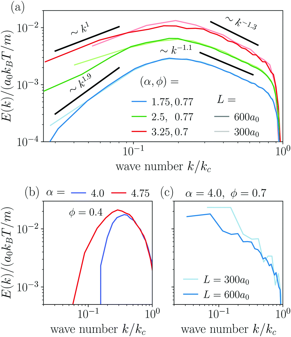
The power spectral densities E(k) calculated from Cv(R) are in accordance with the findings so far. In Fig. 6(a) we compare the power spectral densities E(k) for three different aspect ratios α = 1.75, 2.5, and 3.25 in dense systems. The velocity autocorrelation functions v(R) show the same oscillating decay as already observed above for α = 3.25 and ϕ = 0.6. We called these states active turbulence since the power spectral density E(k) shows a broad peak, which separates two regions from each other with power-law decays towards low and high k. This is characteristic of active turbulence. Close to the characteristic wave number kc = 2π/lS, where energy is inserted from the active motion of the squirmer rods, E(k) decays to zero. The maxima of the power spectral density all roughly occur at 0.2kc, indicating that the pattern size scales with lS, which makes sense when the density is roughly the same.
 | ||
| Fig. 6 (a) Power spectral density E(k) in the turbulent state calculated from the velocity pair-correlation function Cv(R). Light and dark colors correspond to small and large system sizes L, respectively. (b) Power spectral density E(k) in the disordered state and (c) in the dynamic cluster state. | ||
As reported in other experimental51 and theoretical50 studies on polar active fluids, the scaling exponents for the power laws in k are not universal. Towards smaller length scales (larger k), the exponent shows only a weak dependence on the aspect ratio α with values of −1.1 and −1.3, while towards larger length scales we observe a stronger variation of the scaling exponent with aspect ratio. For short squirmer rods with α = 1.75, the power spectral density decays more rapidly with E(k) ∼ k1.9 and for a larger aspect ratio α = 3.25, the power spectral density scales with E(k) ∼ k1. This indicates that for larger aspect ratio patterns at large length scales (small k) are observed more frequently.
For disordered states the power spectra do not follow power laws [cf.Fig. 6(b)]. Instead, they quickly decay towards smaller k, which indicates again that energy is not transported to larger length scales. In contrast, for the dynamic cluster state energy is concentrated at the larger length scales (small k) as expected, while E(k) decays strongly towards smaller length scales [cf.Fig. 6(c)]. To investigate finite size effects, we compare the regular systems of size L = 300a0 to systems with the increased system size of L = 600a0 performed for α = 4 and ϕ = 0.7. In the bigger system the maximum of E(k) shifts to smaller values of k roughly proportional to the change in L which suggests that the maximum correlation length always corresponds to the system size, and no characteristic length scale emerges. At the same time, we observe a decrease of max[E(k)] indicating that the dynamic of the cluster slows down as L increases. This behavior clearly distinguishes the dynamic cluster state from active turbulence, which has an intrinsic characteristic length scale. However, we note that data for larger systems would be necessary to show that the maximum correlation length 1/argmax[E(k)] diverges for infinite system size. Though, this currently exceeds our computational capabilities. Note, the irregular behavior in the curve for L = 300a0 is due to the fact that with increasing α close to the jammed cluster state the dynamics of the clusters slows down and longer simulation times are needed to smooth the curve.
3.4 Puller-type squirmer rods
 | ||
| Fig. 7 (a) State diagram of the puller-type squirmer rods with χ = 1 in the parameter space aspect ratio α versus area fraction ϕ. Snapshots of the system in (b) the swarming state at ϕ = 0.2 and α = 2.5 (only a part of the system is shown), (c) the dynamic cluster state at ϕ = 0.77 and α = 2.5, (d) the single swarm state at ϕ = 0.4 and α = 4.0, and (e) the jammed cluster state at ϕ = 0.77 and α = 4.0. | ||
The most prominent feature of puller-type squirmer rods is that their flow fields strongly promote the formation of small swarms. Even for dilute systems with area fractions down to 0.2, the hydrodynamic interactions between the squirmer rods favor small swarms against the disordered state. Different from the purely steric alignment responsible for swarming neutral squirmer rods,94 pairs of puller-type squirmer rods form T-shaped configurations, although deformed, when they collide. Examples are indicated in the snapshot of Fig. 7(b). This leads to small groups, where several squirmer rods follow a central leader of the group, arranged in a “comet tail” and pointing inwards [Fig. 7(b)]. A similar behavior is also found in ref. 95 and for dry active rods.98 However, we observe that for the hydrodynamically interacting squirmer rods the swarming behavior extends to smaller densities and aspect ratios compared to dry self-propelled rods.61,64 Often the swarms have an asymmetric shape, which then induces curved trajectories (Video 4, ESI†). With increasing area fraction, ϕ ≥ 0.4, swarms also increase in size. However, the overall alignment in the swarms rather decreases. This is due to the low polarity of the small swarms, which then merge in an unordered fashion with increasing ϕ.
For aspect ratios α ≥ 3 we also observe the formation of a single swarm, which collects all squirmer rods in the system [Fig. 7(d) and Video 5, ESI†]. For area fractions ϕ ≥ 0.6 and sufficiently large aspect ratios the single swarm becomes jammed and forms a static cluster state [Fig. 7(e) and Video 6, ESI†]. Reducing the aspect ratio at ϕ = 0.77 to α ≤ 2.5, the jammed cluster becomes dynamic similar to the state observed in pusher-type squirmer rods [Fig. 7(c) and Video 7, ESI†].
v(R) does not become negative. This underlines the tendency of pullers to form two swarming states. To thoroughly distinguish these states, which both give very similar velocity correlation functions, we will further examine the orientational autocorrelations in Section 3.4.3.
 | ||
| Fig. 8 (a) Normalized velocity pair-correlation function v(R) plotted versus distance R for puller-type squirmer rods at constant aspect ratio of α = 4.0. (b) Orientational autocorrelation function Ce(δt) for constant aspect ratio α = 4.0. (c) Orientational autocorrelation function Ce(δt) in dense systems at area fraction ϕ = 0.77. | ||
We have already seen, that even in dilute systems with ϕ = 0.2, the puller-type flow fields locally align the squirmer rods and thereby cause swarming. This is also visible in the velocity correlation function v(R), which is more long-ranged compared to pusher-type rods [Fig. 5(a)]. Thus, squirmer rods are significantly correlated for distances up to R = 2lS. As described in Section 3.4.1, the size of swarms increases with density. For the subsequent area fraction of ϕ = 0.4 the system is already in the single swarm state at the chosen aspect ratio of 4.0. Hence, the velocity correlation function v(R) becomes more long-ranged. At ϕ = 0.6 and ϕ = 0.77, when the system is noticeably in the jammed cluster state, we observe two different features. For ϕ = 0.6, v(R) reaches a plateau, which indicates that the jammed cluster drifts in one direction since the squirmer rods are aligned, on average. At the highest density ϕ = 0.77 the cluster formation takes place more quickly resulting in a disordered structure without drift. Here, the velocity correlation function v(R) decreases and does not exhibit a plateau until R/lS = 5.
In dilute systems with ϕ = 0.2, Ce(δt) decays to zero at around δt = 15lS/v0, meaning that swarms swim a distance of around 7lS until they either rotate, merge with other clusters or dissolve (Video 8, ESI†). For the single swarm state at ϕ = 0.4, we observe a more long-ranged autocorrelation. After a swarm has formed it remains stable but also goes through configurational changes so that partially straight motion is observed interrupted by rotations or turns of the swarm (Video 5, ESI†). As a result, Ce(δt) exhibits a damped oscillation, where the first minimum at δt ≈ 37lS/v0 means that the swarm has rotated by 180°. In the jammed cluster state, we again observe two different features. For ϕ = 0.6, the cluster drifts due to its overall polar order. However, also configurational changes occur, which results in a decay of Ce(δt) towards a non-zero value meaning that the cluster has reached some stable configuration within the observation window. At the higher density ϕ = 0.77, the cluster now has a more random but static arrangement of the rods. Therefore, it hardly drifts and it only rotates very slowly, which causes a very slow decrease of Ce(δt).
Comparing dense systems (ϕ = 0.77) of different aspect ratios to each other, we observe the following characteristics from high to low α [Fig. 8(c)]. For the largest aspect ratio α = 4.75 steric interactions between the rods are most dominant and we find an entirely jammed configuration with constant Ce(δt) = 1. Lowering the aspect ratio, the jammed cluster becomes more and more interrupted by occasional configurational changes, which results in the noticeable but slow decay of Ce(δt) for α = 3.25. In contrast, the dynamic cluster states at α = 1.75 and α = 2.5 show a fast exponential decay of Ce(δt) due to the dynamic rearrangements within the cluster. The decay is faster for the lower aspect ratio, where the rods reorient more easily.
3.5 Variation from pusher to puller-type squirmer rod
In this section, we compare squirmer rods at a constant aspect ration α = 3.25 and vary the swimmer type by the force-dipole strength χ. Furthermore, we performed simulations at different area fractions ϕ. The resulting state diagram is shown in Fig. 9(a). States of neutral squirmer rods are adapted according to ref. 94. | ||
| Fig. 9 (a) State diagram of the squirmer rods for different dipole-strengths χ and area fraction ϕ at an aspect ratio of α = 3.25. The labeled vertical lines indicate the states for which the velocity correlation function is shown in (b and c). (b) Normalized velocity pair-correlation function v(R) for dilute systems with ϕ = 0.2 and different force-dipole strengths χ. Red curves belong to systems in the swarming state and green curves to the disordered state. (c) Normalized velocity pair-correlation function v(R) for ϕ = 0.6. The black curve belongs to the system in the single swarm state, green to the swarming state, and yellow to the turbulent case (d) Power spectral density E(k) for the turbulent state at different χ, ϕ. | ||
For puller-type squirmer rods with χ > 0, we observe that already weak pullers with χ = 0.25 show swarming at the small area fraction of ϕ = 0.2, i. e., the same state we observed in Section 3.4.1 for the highest strength χ = 1.0. Obviously, the force-dipole field, which attracts nearby rods along the rod axis, promotes swarming. However, with increasing ϕ, swarming also extends to weak pusher rods. At higher area fractions ϕ ≥ 0.6, we find single swarm and jammed cluster states due to steric interactions between the rods, where neutral (χ = 0) and puller-type squirmer rods show qualitatively similar behavior.
For pusher-type squirmer rods, χ < 0, we observe a more diverse behavior, which we already noted for χ = 1 in Section 3.3.1. While at ϕ = 0.2 only the disordered state occurs, at ϕ = 0.4 we find a transition from swarming to turbulent to disordered state with increasing pusher strength. The analysis of the power spectral density E(k) reveals that the system with χ = −0.5 is indeed in the turbulent state. Thus, the pusher flow field destabilizes swarming clusters. As a compromise between swarming and disordered states, active turbulence occurs in conjunction with steric repulsion. Increasing density further to ϕ = 0.6, steric repulsion stabilizes swarming clusters and active turbulence is shifted to the largest pusher strength χ = −1. Finally, at ϕ = 0.77 the pusher flow field destabilizes the jammed cluster of neutral and puller-type squirmer rods, which then becomes dynamic.
v(R) as defined in eqn (3). In Fig. 9(b) we compare v(R) in dilute systems with ϕ = 0.2 for different force-dipole strengths χ to each other. The collective dynamics is mainly governed by hydrodynamic interactions. Fig. 9(c) shows v(R) for the larger area fraction ϕ = 0.6, where a transition to the turbulent state occurs at χ = −1.
In the dilute systems, all the velocity pair-correlation functions in the swarming state of puller-type swimmers (χ > 0) are nearly identical and show correlations up to circa 2lS [Fig. 9(b)]. This indicates that the mechanism behind swarm formation is fully established already at small dipole strength. Pusher-type squirmer rods (χ <0) only exhibit the disordered state and no swarms, so v(R) is more short-ranged compared to pullers. Pushers prefer to order side by side and therefore pronounced peaks at closest distance R = lS/α are observed compared to puller rods. Furthermore, we observe anti-correlations with v(R) < 0 starting at distances R between lS and 2lS. They belong to pusher rods approaching each other head on.
At the higher area fraction ϕ = 0.6, we observe the single swarm, swarming, and turbulent states [Fig. 9(c)]. In the single swarm state observed for weak pullers (χ = 0.25), v(R) is long-ranged and shows significant correlations for all recorded distances up to R = 5lS. In the swarming state that emerges for pushers at χ = −0.25 and −0.5 the correlation length of v(R) decreases with increasing force-dipole strength. At χ = −0.5 it is around R = 2lS. In the turbulent state at χ = −1, v(R) becomes even more short-ranged and negative at R = lS due to the occurrence of vortices.
In Fig. 9(d) we compare the power spectral densities E(k) for three systems in the turbulent state at α = 3.25. All three spectra show a regular cascade towards large k (small scales) and a second cascade towards small k (large scales). At large k all three power spectral densities show roughly the same scaling behavior E(k) ∼ k−1.3. Furthermore, the curves for (χ, ϕ) = (−0.5, 0.4) and (χ, ϕ) = (−1.0, 0.6) coincide in the range from k = 0.2kc to kc, which includes the maximum of both spectra. For the second cascade, different scaling exponents are observed. At χ = −1 the power spectral density decays more rapidly in the system with ϕ = 0.6 following a scaling E(k) ∼ k2, while in the denser system (ϕ = 0.7) the scaling is E(k) ∼ k1. Furthermore, the maximum of E(k) shifts to a smaller wave number k, which implies a larger intrinsic length scale of the turbulent pattern. For the system with the smaller pusher strength, χ = −0.5, the scaling follows E(k) ∼ k1.4, thus, it is situated between the two cases just discussed.
4 Summary and conclusion
In this article, we investigated the dynamic states of pusher and puller-type squirmer rods. Varying the head-to-tail anisotropy parameter χ of the surface slip-velocity field of the squirmer rod, we are able to smoothly tune the force-dipole strength of the resulting flow field between a pusher and puller.For pushers with largest force-dipole strength χ = −1, we observe a new turbulent state along with other modifications in the state diagram compared to neutral squirmer rods. In dilute systems, where steric interactions are less important, the pusher flow field suppresses the formation of the swarming states so that the disordered state extends to larger area fractions and aspect ratios. When steric interactions and thereby steric alignment of the rods become more important with increasing area fraction, the turbulent state emerges at small aspect ratios. To observe it for weaker pusher strengths at constant aspect ratio, one has to decrease the area fraction, which confirms the importance of steric interactions for the turbulent state. The velocity pair-correlation function decays and exhibits negative regions after one or two swimmer lengths, which indicates a characteristic length scale. At the same time, the power spectral density of the velocity fluctuations shows two energy cascades at small and large wave numbers with power-law scaling and non-universal exponents as reported in other works on active turbulence in polar fluids.49,50,97 Increasing the area fraction further, a transition to the dynamic cluster state occurs at medium aspect ratios, which is reminiscent of the turbulent state but without the characteristic energy cascades. This is in contrast to soft active rods, where jammed states occur,42,63 which are, however, destroyed for strong enough self-propulsion.112 At larger aspect ratios, steric interactions become more important. Here, pushers resemble the dynamics of neutral squirmer rods94 and dry active rods,61,62 such that, instead of the turbulent and dynamic swarm state, a single swarm and jammed cluster are observed.
For pullers at all studied force-dipole strengths χ and in the most dilute system at ϕ = 0.2, hydrodynamic interactions already promote the swarming state instead of the disordered state observed for neutral rods. At smaller aspect ratios and the largest area fraction, the dynamic cluster state occurs, while for larger aspect ratios swarming and dynamic clustering are replaced by a single swarm and jammed cluster state.
Thus, our study clearly indicates the importance of the type of the swimmer flow field for the occurring states. Although comparable states are often found for dry self-propelled rods, for squirmer rods their occurrence in the state diagram crucially depends on the specific hydrodynamic flow field. Specifically, active turbulence is only found for pushers and puller type flow fields greatly enhance the formations of swarms. Additionally, the different scaling exponents in the turbulent state show that steric interactions, tuned by rod density, play an important role for this state. All in all, the turbulent state occurs as a compromise between disordering hydrodynamic pusher flow fields and aligning steric interactions. Therefore, with our work we contribute to the insights how various biological propulsion strategies determine the collective motion of microswimmers.
In future work, it will be interesting to investigate collective dynamics of pusher and puller-type squirmer rods also in the bulk fluid, where the hydrodynamic force-dipole has the most long-range or dominant flow field. Likewise, implementing a liquid–air interface using a slip-boundary condition at one wall of the Hele-Shaw geometry, would provide a realistic modeling of recent experiments, where bacteria move close to a fluid–air interface.113
Conflicts of interest
There are no conflicts to declare.Acknowledgements
We thank Felix Rühle, Reinier van Buel and Josua Grawitter for helpful discussions on the topic of the manuscript. We also acknowledge financial support from the Collaborative Research Center 910 funded by Deutsche Forschungsgemeinschaft.References
- F. Partensky, W. R. Hess and D. Vaulot, Microbiol. Mol. Biol. Rev., 1999, 63, 106–127 CrossRef CAS PubMed
.
- P. G. Falkowski, Phys. Rev., 1994, 39, 235–258 CAS
- C. B. Field, M. J. Behrenfeld, J. T. Randerson and P. Falkowski, Science, 1998, 281, 237–240 CrossRef CAS PubMed
- A. L. Demain, Trends Biotechnol., 2000, 18, 26–31 CrossRef CAS PubMed
- I. M. Banat, A. Franzetti, I. Gandolfi, G. Bestetti, M. G. Martinotti, L. Fracchia, T. J. Smyth and R. Marchant, Appl. Microbiol. Biotechnol., 2010, 87, 427–444 CrossRef CAS PubMed
- S. N. Naik, V. V. Goud, P. K. Rout and A. K. Dalai, Renewable Sustainable Energy Rev., 2010, 14, 578–597 CrossRef CAS
- D. M. Alonso, J. Q. Bond and J. A. Dumesic, Green Chem., 2010, 12, 1493–1513 RSC
- H.-J. Huang, S. Ramaswamy, U. Tschirner and B. Ramarao, Sep. Purif. Technol., 2008, 62, 1–21 CrossRef CAS
- M. Wagner, A. Loy, R. Nogueira, U. Purkhold, N. Lee and H. Daims, Antonie van Leeuwenhoek, 2002, 81, 665–680 CrossRef CAS PubMed
- I. Schmidt, O. Sliekers, M. Schmid, E. Bock, J. Fuerst, J. G. Kuenen, M. S. Jetten and M. Strous, FEMS Microbiol. Rev., 2003, 27, 481–492 CrossRef CAS PubMed
- E. Lauga and T. R. Powers, Rep. Prog. Phys., 2009, 72, 096601 CrossRef
- M. C. Marchetti, J.-F. Joanny, S. Ramaswamy, T. B. Liverpool, J. Prost, M. Rao and R. A. Simha, Rev. Mod. Phys., 2013, 85, 1143 CrossRef CAS
- A. Zöttl and H. Stark, J. Phys.: Condens. Matter, 2016, 28, 253001 CrossRef
- M. Polin, I. Tuval, K. Drescher, J. P. Gollub and R. E. Goldstein, Science, 2009, 325, 487–490 CrossRef CAS PubMed
- J. Elgeti, R. G. Winkler and G. Gompper, Rep. Prog. Phys., 2015, 78, 056601 CrossRef CAS PubMed
- H. C. Berg, Annu. Rev. Biochem., 2003, 72, 19–54 CrossRef CAS PubMed
- R. Vogel and H. Stark, Phys. Rev. Lett., 2013, 110, 158104 CrossRef PubMed
- T. C. Adhyapak and H. Stark, Phys. Rev. E, 2015, 92, 052701 CrossRef PubMed
- J. Tailleur and M. Cates, Europhys. Lett., 2009, 86, 60002 CrossRef
- C. O. Reichhardt and C. Reichhardt, Annu. Rev. Condens. Matter Phys., 2017, 8, 51–75 CrossRef
- R. Di Leonardo, L. Angelani, D. Dell’Arciprete, G. Ruocco, V. Iebba, S. Schippa, M. P. Conte, F. Mecarini, F. De Angelis and E. Di Fabrizio, Proc. Natl. Acad. Sci. U. S. A., 2010, 107, 9541–9545 CrossRef CAS PubMed
- A. Sokolov, M. M. Apodaca, B. A. Grzybowski and I. S. Aranson, Proc. Natl. Acad. Sci. U. S. A., 2010, 107, 969–974 CrossRef CAS PubMed
- M. Knežević and H. Stark, New J. Phys., 2020, 22, 113025 CrossRef
- M. Enculescu and H. Stark, Phys. Rev. Lett., 2011, 107, 058301 CrossRef PubMed
- F. Rühle and H. Stark, Eur. Phys. J. E: Soft Matter Biol.
Phys., 2020, 43, 1–17 CrossRef PubMed
- J. R. Blake, J. Fluid Mech., 1971, 46, 199–208 CrossRef
- S. E. Spagnolie and E. Lauga, J. Fluid Mech., 2012, 700, 105–147 CrossRef
- S. Thutupalli, R. Seemann and S. Herminghaus, New J. Phys., 2011, 13, 073021 CrossRef
- J. Gachelin, A. Rousselet, A. Lindner and E. Clement, New J. Phys., 2014, 16, 025003 CrossRef
- M. Theers, E. Westphal, K. Qi, R. G. Winkler and G. Gompper, Soft Matter, 2018, 14, 8590–8603 RSC
- Ö. Duman, R. E. Isele-Holder, J. Elgeti and G. Gompper, Soft Matter, 2018, 14, 4483–4494 RSC
- J.-T. Kuhr, F. Rühle and H. Stark, Soft Matter, 2019, 15, 5685–5694 RSC
- M. Hennes, K. Wolff and H. Stark, Phys. Rev. Lett., 2014, 112, 238104 CrossRef PubMed
- M. J. Kim and K. S. Breuer, Small, 2008, 4, 111–118 CrossRef CAS PubMed
- V. Schaller, C. Weber, C. Semmrich, E. Frey and A. R. Bausch, Nature, 2010, 467, 73–77 CrossRef CAS PubMed
- H. Wioland, F. G. Woodhouse, J. Dunkel, J. O. Kessler and R. E. Goldstein, Phys. Rev. Lett., 2013, 110, 268102 CrossRef PubMed
- D. Khoromskaia and G. P. Alexander, New J. Phys., 2017, 19, 103043 CrossRef
- Y. Sumino, K. H. Nagai, Y. Shitaka, D. Tanaka, K. Yoshikawa, H. Chaté and K. Oiwa, Nature, 2012, 483, 448–452 CrossRef CAS PubMed
- T. Sánchez, D. T. N. Chen, S. J. DeCamp, M. Heymann and Z. Dogic, Nature, 2012, 491, 431 CrossRef PubMed
- S. J. DeCamp, G. S. Redner, A. Baskaran, M. F. Hagan and Z. Dogic, Nat. Mater., 2015, 14, 1110–1115 CrossRef CAS PubMed
- F. C. Keber, E. Loiseau, T. Sanchez, S. J. DeCamp, L. Giomi, M. J. Bowick, M. C. Marchetti, Z. Dogic and A. R. Bausch, Science, 2014, 345, 1135–1139 CrossRef CAS PubMed
- H. Wensink and H. Löwen, J. Phys.: Condens. Matter, 2012, 24, 464130 CrossRef CAS PubMed
- J. Dunkel, S. Heidenreich, K. Drescher, H. H. Wensink, M. Bär and R. E. Goldstein, Phys. Rev. Lett., 2013, 110, 228102 CrossRef PubMed
- C. Dombrowski, L. Cisneros, S. Chatkaew, R. E. Goldstein and J. O. Kessler, Phys. Rev. Lett., 2004, 93, 098103 CrossRef PubMed
- C. W. Wolgemuth, Biophys. J., 2008, 95, 1564–1574 CrossRef CAS PubMed
- S. Heidenreich, J. Dunkel, S. H. Klapp and M. Bär, Phys. Rev. E, 2016, 94, 020601 CrossRef PubMed
- R. Alert, J.-F. Joanny and J. Casademunt, Nat. Phys., 2020, 16, 682–688 Search PubMed
- B. Martnez-Prat, R. Alert, F. Meng, J. Ignés-Mullol, J.-F. Joanny, J. Casademunt, R. Golestanian and F. Sagués, Phys. Rev. X, 2021, 11, 031065 Search PubMed
- R. Alert, J. Casademunt and J.-F. Joanny, Annu. Rev. Condens. Matter Phys., 2022, 13, 143–170 Search PubMed
- V. Bratanov, F. Jenko and E. Frey, Proc. Natl. Acad. Sci. U. S. A., 2015, 112, 15048–15053 CrossRef CAS PubMed
- H. H. Wensink, J. Dunkel, S. Heidenreich, K. Drescher, R. E. Goldstein, H. Löwen and J. M. Yeomans, Proc. Natl. Acad. Sci. U. S. A., 2012, 109, 14308 CrossRef CAS PubMed
- K. Qi, E. Westphal, G. Gompper and R. G. Winkler, Phys. Rev. Lett., 2020, 124, 068001 CrossRef CAS PubMed
- A. Doostmohammadi, T. N. Shendruk, K. Thijssen and J. M. Yeomans, Nat. Commun., 2017, 8, 1–7 CrossRef PubMed
- S.-Z. Lin, W.-Y. Zhang, D. Bi, B. Li and X.-Q. Feng, Commun. Phys., 2021, 4, 1–9 CrossRef
- A. Doostmohammadi, S. P. Thampi, T. B. Saw, C. T. Lim, B. Ladoux and J. M. Yeomans, Soft Matter, 2015, 11, 7328–7336 RSC
- T. Vicsek, A. Czirók, E. Ben-Jacob, I. Cohen and O. Shochet, Phys. Rev. Lett., 1995, 75, 1226 CrossRef CAS PubMed
- G. Grégoire and H. Chaté, Phys. Rev. Lett., 2004, 92, 025702 CrossRef PubMed
- H. Chaté, F. Ginelli, G. Grégoire, F. Peruani and F. Raynaud, Eur. Phys. J. B, 2008, 64, 451–456 CrossRef
- R. Großmann, P. Romanczuk, M. Bär and L. Schimansky-Geier, Phys. Rev. Lett., 2014, 113, 258104 CrossRef PubMed
- M. C. Bott, F. Winterhalter, M. Marechal, A. Sharma, J. M. Brader and R. Wittmann, Phys. Rev. E, 2018, 98, 012601 CrossRef CAS PubMed
- F. Peruani, A. Deutsch and M. Bär, Phys. Rev. E: Stat., Nonlinear, Soft Matter Phys., 2006, 74, 030904 CrossRef PubMed
- Y. Yang, V. Marceau and G. Gompper, Phys. Rev. E: Stat., Nonlinear, Soft Matter Phys., 2010, 82, 031904 CrossRef PubMed
- M. Abkenar, K. Marx, T. Auth and G. Gompper, Phys. Rev. E: Stat., Nonlinear, Soft Matter Phys., 2013, 88, 062314 CrossRef PubMed
- S. Weitz, A. Deutsch and F. Peruani, Phys. Rev. E: Stat., Nonlinear, Soft Matter Phys., 2015, 92, 012322 CrossRef PubMed
- H. Jiang and Z. Hou, Soft Matter, 2014, 10, 1012–1017 RSC
- R. E. Isele-Holder, J. Elgeti and G. Gompper, Soft Matter, 2015, 11, 7181–7190 RSC
- M. Hennes, K. Wolff and H. Stark, Phys. Rev. Lett., 2014, 112, 238104 CrossRef PubMed
- H. Jeckel, E. Jelli, R. Hartmann, P. K. Singh, R. Mok, J. F. Totz, L. Vidakovic, B. Eckhardt, J. Dunkel and K. Drescher, Proc. Natl. Acad. Sci. U. S. A., 2019, 116, 1489–1494 CrossRef CAS PubMed
- A. Zöttl and H. Stark, Eur. Phys. J. E: Soft Matter Biol. Phys., 2018, 41, 61 CrossRef PubMed
- G. Rückner and R. Kapral, Phys. Rev. Lett., 2007, 98, 150603 CrossRef PubMed
- I. O. Götze and G. Gompper, Phys. Rev. E: Stat., Nonlinear, Soft Matter Phys., 2010, 82, 041921 CrossRef PubMed
- P. de Buyl and R. Kapral, Nanoscale, 2013, 5, 1337–1344 RSC
- A. Zöttl and H. Stark, Phys. Rev. Lett., 2014, 112, 118101 CrossRef PubMed
- J. Blaschke, M. Maurer, K. Menon, A. Zöttl and H. Stark, Soft Matter, 2016, 12, 9821–9831 RSC
- A. Zöttl and J. M. Yeomans, Nat. Phys., 2019, 15, 554–558 Search PubMed
- A. W. Zantop and H. Stark, Soft Matter, 2020, 16, 6400–6412 RSC
- T. Eisenstecken, J. Hu and R. G. Winkler, Soft Matter, 2016, 12, 8316–8326 RSC
- M. Wagner and M. Ripoll, Europhys. Lett., 2017, 119, 66007 CrossRef
- F. J. Schwarzendahl and M. G. Mazza, J. Chem. Phys., 2019, 150, 184902 CrossRef PubMed
- J. de Graaf, H. Menke, A. J. Mathijssen, M. Fabritius, C. Holm and T. N. Shendruk, J. Chem. Phys., 2016, 144, 134106 CrossRef PubMed
- A. Pandey, P. S. Kumar and R. Adhikari, Soft Matter, 2016, 12, 9068–9076 RSC
- M. Kuron, P. Stärk, C. Burkard, J. De Graaf and C. Holm, J. Chem. Phys., 2019, 150, 144110 CrossRef PubMed
- Z. Ouyang and J. Lin, Phys. Fluids, 2021, 33, 073302 CrossRef CAS
- J. Toner and Y. Tu, Phys. Rev. Lett., 1995, 75, 4326 CrossRef CAS PubMed
- J. Swift and P. C. Hohenberg, Phys. Rev. A, 1977, 15, 319 CrossRef
- V. M. Worlitzer, G. Ariel, A. Be'er, H. Stark, M. Bär and S. Heidenreich, New J. Phys., 2021, 23, 033012 CrossRef CAS
- H. Reinken, S. H. Klapp, M. Bär and S. Heidenreich, Phys. Rev. E, 2018, 97, 022613 CrossRef CAS PubMed
- D. Saintillan and M. J. Shelley, Phys. Rev. Lett., 2007, 99, 058102 CrossRef PubMed
- A. Baskaran and M. C. Marchetti, Proc. Natl. Acad. Sci. U. S. A., 2009, 106, 15567–15572 CrossRef CAS PubMed
- N. Yoshinaga and T. B. Liverpool, Phys. Rev. E, 2017, 96, 020603 CrossRef PubMed
- M. Lighthill, Commun. Pur. Appl. Math., 1952, 5, 109–118 CrossRef
- M. T. Downton and H. Stark, J. Phys.: Condens. Matter, 2009, 21, 204101 CrossRef PubMed
- A. W. Zantop and H. Stark, J. Chem. Phys., 2021, 154, 024105 CrossRef CAS PubMed
- A. W. Zantop and H. Stark, J. Chem. Phys., 2021, 155, 134904 CrossRef CAS PubMed
- K. Kyoya, D. Matsunaga, Y. Imai, T. Omori and T. Ishikawa, Phys. Rev. E: Stat., Nonlinear, Soft Matter Phys., 2015, 92, 063027 CrossRef CAS PubMed
- M. Theers, E. Westphal, G. Gompper and R. G. Winkler, Soft Matter, 2016, 12, 7372–7385 RSC
- K. Qi, E. Westphal, G. Gompper and R. G. Winkler, Commun. Phys., 2022, 5, 1–12 CrossRef
- M. Bär, R. Großmann, S. Heidenreich and F. Peruani, Annu. Rev. Condens. Matter Phys., 2020, 11, 441–466 CrossRef
- A. J. Mathijssen, A. Doostmohammadi, J. M. Yeomans and T. N. Shendruk, J. Fluid Mech., 2016, 806, 35–70 CrossRef
- A. Malevanets and R. Kapral, J. Chem. Phys., 1999, 110, 8605–8613 CrossRef CAS
- A. Lamura, G. Gompper, T. Ihle and D. Kroll, Europhys. Lett., 2001, 56, 319 CrossRef CAS
- I. O. Götze, H. Noguchi and G. Gompper, Phys. Rev. E: Stat., Nonlinear, Soft Matter Phys., 2007, 76, 046705 CrossRef PubMed
- J. D. Weeks, D. Chandler and H. C. Andersen, J. Chem. Phys., 1971, 54, 5237–5247 CrossRef CAS
- A. Dullweber, B. Leimkuhler and R. McLachlan, J. Chem. Phys., 1997, 107, 5840–5851 CrossRef CAS
- H. Jeckel, E. Jelli, R. Hartmann, P. K. Singh, R. Mok, J. F. Totz, L. Vidakovic, B. Eckhardt, J. Dunkel and K. Drescher, Proc. Natl. Acad. Sci. U. S. A., 2019, 116, 1489–1494 CrossRef CAS PubMed
- J. Deng, M. Molaei, N. G. Chisholm and K. J. Stebe, Langmuir, 2020, 36, 6888–6902 CrossRef CAS PubMed
- L. Vaccari, M. Molaei, T. H. Niepa, D. Lee, R. L. Leheny and K. J. Stebe, Adv. Colloid Interface Sci., 2017, 247, 561–572 CrossRef CAS PubMed
- N. Liron and S. Mochon, J. Eng. Mech., 1976, 10, 287–303 Search PubMed
- N. Oyama, J. J. Molina and R. Yamamoto, Phys. Rev. E, 2016, 93, 043114 CrossRef PubMed
-
U. Frisch and A. N. Kolmogorov, Turbulence: the legacy of AN Kolmogorov, Cambridge University Press, 1995 Search PubMed
-
A. D. Poularikas, Transforms and applications handbook, CRC press, 2018 Search PubMed
- R. Großmann, I. S. Aranson and F. Peruani, Nat. Commun., 2020, 11, 1–12 CrossRef PubMed
- D. Nishiguchi, I. S. Aranson, A. Snezhko and A. Sokolov, Nat. Commun., 2018, 9, 1–8 CrossRef PubMed
Footnote |
| † Electronic supplementary information (ESI) available: We provide eight videos of different collective dynamic states in the top view. Videos 1–3 show pusher rods in the turbulent (1), single swarm (2) and dynamic cluster state (3). Videos 4–8 show puller rods in the swarming (4 and 8), single swarm (5), jammed cluster (6), and dynamic cluster state (7). See DOI: https://doi.org/10.1039/d2sm00449f |
| This journal is © The Royal Society of Chemistry 2022 |