
The role of excess attractive particles in the elasticity of high internal phase Pickering emulsions†
Junsu
Chae
 a,
Siyoung Q.
Choi
*a and
KyuHan
Kim
*b
a,
Siyoung Q.
Choi
*a and
KyuHan
Kim
*b
aDepartment of Chemical and Biomolecular Engineering, KAIST, Daejeon, 34141, Korea. E-mail: sqchoi@kaist.ac.kr
bDepartment of Chemical and Biomolecular Engineering, SeoulTech, Seoul, 01811, Korea. E-mail: kyuhankim@seoultech.ac.kr
First published on 17th November 2021
Abstract
A high internal phase emulsion (HIPE), which has a volume fraction of dispersed phase of over 74%, shows a solid-like property because of concentrated polyhedral droplets. Although many studies have proposed theoretical and empirical models to explain the rheological properties of HIPEs, most of them are only limited to the emulsions stabilized by surfactants. In the case of high internal phase Pickering emulsions (HIPPEs), much greater values of elastic modulus have been reported, compared to those of surfactant-stabilized HIPEs, but so far, there have been no clear explanations for this. In this study, we investigate how colloidal particles attribute to the significantly high elasticity of HIPPEs, specifically considering two different contributions, namely, interfacial rheological properties and bulk rheological properties. Our results reveal that the flocculated structures of colloidal particles that possess a significant elasticity can be interconnected between dispersed droplets. Furthermore, this elastic structure is a crucial factor in the high elasticity of HIPPEs, which is also supported by a simple theoretical model.
1. Introduction
High internal phase emulsion (HIPE) systems in which the volume fraction of dispersed liquid is higher than ϕ > 0.74 are mostly thermodynamically unstable due to their large interfacial energy. Many researchers have used a large amount of surfactant, which prevents liquid droplets from merging.1–4 However, according to previous studies, colloidal particles can also effectively stabilize high internal phase emulsions,5–7 and they are even known to be a better stabilizer than surfactants for the following reasons. Colloidal particles can easily be adsorbed onto a liquid–liquid interface by decreasing the interfacial area, and the detachment energy of colloidal particles with a sub-micron size of ∼105kBT, which means that an almost irreversible attachment of colloidal particles occurs.8 In addition, colloidal particles are much larger than surfactant molecules, so they can prevent droplet coalescence more effectively.9 Lastly, they can be laterally flocculated at the interface by capillary attraction, resulting in a more rigid interfacial layer.10–14Although these stable HIPEs are composed of two viscous liquid phases, a dispersed liquid phase and a continuous liquid phase, they can behave like a viscoelastic solid.15–22 In HIPEs, the volume fraction of the dispersed phase is higher than the close packing density of monodispersed spheres, thereby resulting in jammed polyhedral droplets inside the continuous phase. Furthermore, this distinctive structure makes it possible for the stored energy of the droplets to effectively transfer to the entire system because the energy dissipation may rarely occur through the very thin continuous phase. Most studies of HIPEs found that the elasticity of HIPEs is proportional to the total area of the interface because its solid-like property (or elasticity) primarily comes from the interfacial energy of the system.16,18,21,23 In particular, these previous studies propose a relationship between the volume fraction of the dispersed phase and the elasticity of HIPEs, and accordingly, they also claim that surface tension, droplet size, and the volume fraction of the dispersed phase are key parameters which determine the elasticity of HIPEs. However, these models only focus on emulsions with surfactants,15–21 and few papers have described the elasticity of high internal phase Pickering emulsions (HIPPEs).24–28 In addition, some recent studies found that the elasticity of HIPPEs is much higher than that of surfactant-stabilized HIPEs,25,28–31 suggesting that colloidal particles might significantly contribute to the elasticity of HIPPEs, even though their role is still unclear.
In this study, to clearly elucidate the role of colloidal particles, we took several different approaches in varying the concentration of the particles. First, we measured the rheological properties of HIPPEs stabilized by two different sized particles. Then, we investigated the interfacial rheological properties of 2D densely-packed particle layers considering the isotherm measurement of the particle layers at the interface, and also measured the bulk properties of the continuous phase, that is, the residual concentration of the particles and their rheological properties. In addition, we established a new theoretical model that shows a correlation between the rigid colloidal structure in the continuous phase and G′ of HIPPEs. Lastly, we measured the rheological properties of the HIPPEs in the presence of salts for controlling the size of particle aggregates in the thin film between dispersed droplets. According to the results of these experimental and theoretical investigations, we confirmed for the first time that significantly large values of elasticity of the HIPPEs mainly originate from the elasticity of the thin continuous phase. This elasticity can occur due to the formation of flocculated structures of excess colloidal particles in the thin continuous film.
2. Materials and methods
Preparation of emulsions
A brief scheme for the fabrication of HIPPEs is shown in Fig. 1. Before the emulsification process, each particle suspension for 21 nm TiO2 nanoparticles (Sigma Aldrich) and 100 nm TiO2 nanoparticles (Sigma Aldrich) was prepared with 20 wt% and 15 wt% in deionized water, respectively, via 1 hour sonication (WUC-D10H, DAIHAN Scientific). Here, both nanoparticles were utilized without further purification, and without performing any surface treatments for the hydrophobic functionalization of nanoparticles. Then, oil-in-water (O/W) emulsions with a volume fraction of dispersed phase (ϕ) of 0.85 were fabricated by mixing 3.55 mL hexadecane (Sigma Aldrich) with 0.45 mL of TiO2 suspension through 1 min homogenization (PT 1300 E, KINEMATICA) at 16![[thin space (1/6-em)]](https://www.rsc.org/images/entities/char_2009.gif) 000 rpm. The concentration of the TiO2 nanoparticles in the continuous phase of emulsions was varied from 1 wt% to 20 wt% for 21 nm particles and from 1 wt% to 15 wt% for 100 nm particles, and highly stable HIPEs were made at the given particle concentrations. They did not flow even when the vial was turned over as shown in Fig. 1.
000 rpm. The concentration of the TiO2 nanoparticles in the continuous phase of emulsions was varied from 1 wt% to 20 wt% for 21 nm particles and from 1 wt% to 15 wt% for 100 nm particles, and highly stable HIPEs were made at the given particle concentrations. They did not flow even when the vial was turned over as shown in Fig. 1.
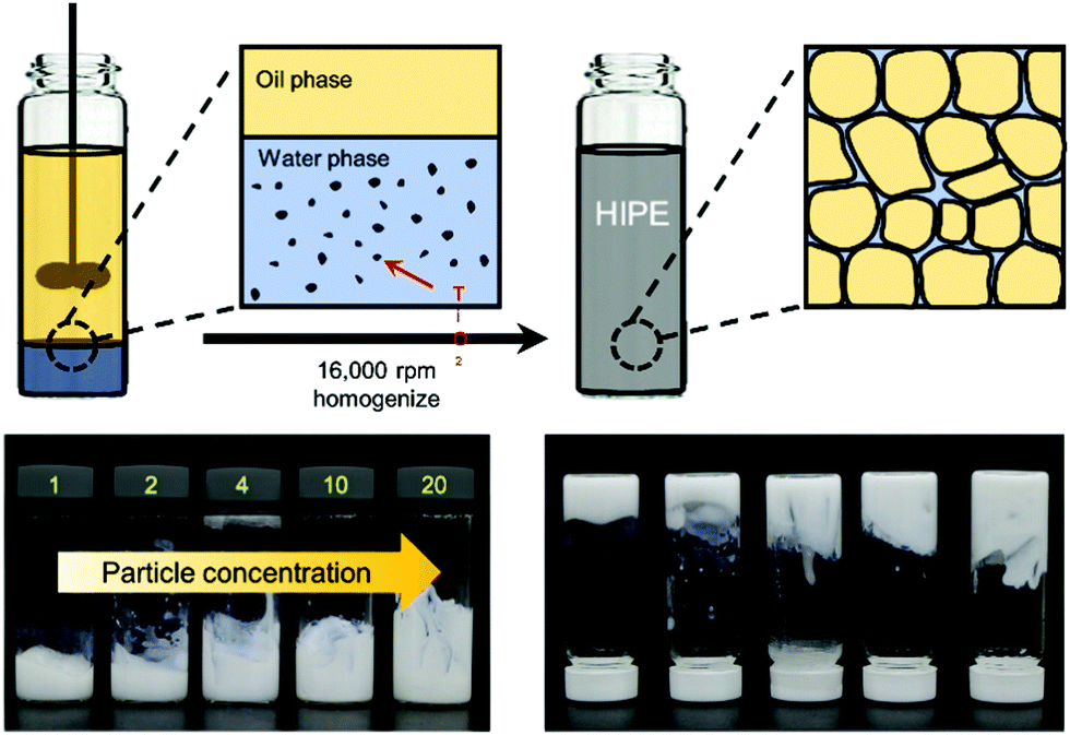 | ||
| Fig. 1 Illustrations showing the fabrication process of high internal phase Pickering emulsions (HIPPEs), stabilized by TiO2 nanoparticles. The bottom pictures are the HIPPE samples (ϕ = 0.85) of different particle concentrations. No significant flow was observed, even though the samples are turned over. | ||
For the modification of the surface charge of the TiO2 particles in the HIPPE samples, sodium chloride (Sigma Aldrich) and calcium chloride (Sigma Aldrich) were added to the 4 wt%-TiO2 suspensions, respectively. The concentration of each salt in the particle suspension was adjusted to 1, 10, and 100 mM, respectively, while the volume fraction of the dispersed phase was fixed to 85%.
Rheology measurement
Rheological properties of the HIPPE samples were measured with a strain-controlled rheometer (MCR 302, Anton Paar). Prior to the rheological measurement, 0.6 mL of the HIPPE sample was loaded on the bottom plate of the rheometer using a micropipette. To minimize the destabilization of the sample while transferring it through the micropipette tip, we cut the end of the tip, so that a lower shear rate could be applied to the sample. Oscillatory shear rheological measurements were conducted for each sample with two experimental procedures: a frequency sweep experiment (0.1–100 rad s−1) was conducted at the fixed linear strain (0.1%), and a strain amplitude sweep experiment (0.01–100%) was conducted at the fixed angular frequency (10 rad s−1). All measurements were conducted in a 1 mm-gap between two parallel plates with a diameter of 25 mm.Size measurement of droplets and particles in HIPPEs
The size of the droplets in each HIPPE sample was measured via optical micrographs (Olympus, BX51). Here, the HIPPE samples were first diluted to a volume fraction lower than 0.7 by adding DI water, and the sample was then spread out until no vertical overlap of droplets occurred (Fig. S2, ESI†). In order to accurately measure the droplet size, more than 200 droplet images were taken, and image analysis was performed using the ImageJ program.The size of the TiO2 nanoparticles was measured using a dynamic light scattering technique (Zetasizer, Malvern). For accurate size measurement, diluted particle suspensions for 21 nm TiO2 and for 100 nm TiO2 were prepared at concentrations of 0.005 wt%.
Measurement of interfacial properties
The surface pressure of the TiO2 nanoparticles along with the interfacial concentration of the particles at the air–water interface was measured using a customized Langmuir-trough system. Here, a 20 wt% TiO2 suspension was first introduced into the trough, and the surface pressure was then measured with the Wilhelmy plate tensiometer (RIEGLER and Kirstein GmbH) while the surface area changed from 48 cm2 to 5 cm2 at 23 °C.The surface pressure of TiO2 particles at the oil–water interface was measured with a customized pendant-drop method. Prior to the measurement, hexadecane (Sigma Aldrich, 99%) was filtered with alumina particles for purification. The purified hexadecane was then used as a bulk phase, and droplets of TiO2-particle suspensions with various concentrations were hung at the tip of the needle. The surface pressure was measured for 30 min.
Determining the number of particles adsorbed at the surface of droplets and remaining in the continuous phase
UV-vis spectroscopy (UV-2600, SHIMADZU) was utilized to measure the concentration of TiO2 particles in a continuous phase of HIPPEs. Before the measurement, calibration curves for TiO2 suspensions were first obtained at 290 nm for 21 nm particles and 353 nm for 100 nm particles, and we confirmed that linear regressions worked well up to 10−4 wt% of the particle concentration. For calculating the number of particles adsorbed at the surface of droplets in the HIPPEs, the prepared HIPPEs were first diluted with water, and the continuous phase was then collected. Here, the degree of dilution was adjusted from 10-fold to 100-fold to obtain the absorbance peak with a magnitude between 0 and 1. According to the calibration curves and the spectroscopic data for the diluted continuous phase, the concentration of the diluted continuous phase of HIPPEs was first calculated. Then the number of particles remaining in the continuous phase and adsorbed at the surface of the droplets could be calculated.3. Results and discussion
3.1. Rheological properties of HIPPEs
According to the previous studies on high internal phase emulsions (HIPEs),15,17,18 their solid-like properties can be revealed by the dominant shear elastic modulus (G′) compared to the shear viscous modulus (G’’) in linear oscillatory measurements (Fig. S1, ESI†). It was also demonstrated that G′ is proportional to the total interfacial energy of the HIPE system (more precisely, it is proportional to the interfacial tension of water/oil (σ) and the volume fraction of the dispersed phase (ϕ) but inversely proportional to droplet size (r)). If the volume fraction of the dispersed phase is fixed, G′ is proportional to (σ/r), which is in good agreement with the definition of the storage modulus, the energy stored in a unit volume (G′ ∼ πr2σ/πr3 ∼ σ/r). Therefore, the normalization of G′ by (σ/r) is effective for comparing the elastic properties of emulsions whose liquid composition and droplet size are quite different.According to rheological experiments for the paraffin oil-in-water emulsion model systems stabilized by anionic surfactants with various volume fractions,17 Princen et al. proposed that the normalized G′s must be constant if the volume fraction is fixed. However, high internal phase Pickering emulsions (HIPPEs) that are stabilized by TiO2 particles of two varied sizes (2l nm and 100 nm) at 0.85 of the fraction of the dispersed phase indicate a significantly different result compared to that of the model systems. Specifically, as the concentration of particles in water increases from 1 wt% to 20 wt% at the fixed volume fraction of 0.85 of the dispersed phases, a significant increase of G′ in the HIPPEs with 21 nm particles initially occurs, and no further increase was observed after 10 wt% while G′s of HIPPEs with 100 nm particles seems to increase monotonically, as shown in Fig. 2a. In addition, the size of dispersed droplets for the HIPPEs with 21 nm particles increased by a factor of 10 as the particle concentration changed from 1 wt% to 20 wt%, while the 100 nm particles remained almost constant (Fig. 2b). Here, it is expected that more particles can stabilize a larger interfacial area, thereby possibly resulting in a monotonic decrease of droplet size.32 This discrepancy probably occurs because the TiO2 particles exist as aggregates with their relatively strong van der Waals attraction,33 so that they can cover a much smaller area than when they are dispersed as single colloids. The details of this particle aggregate are described later.
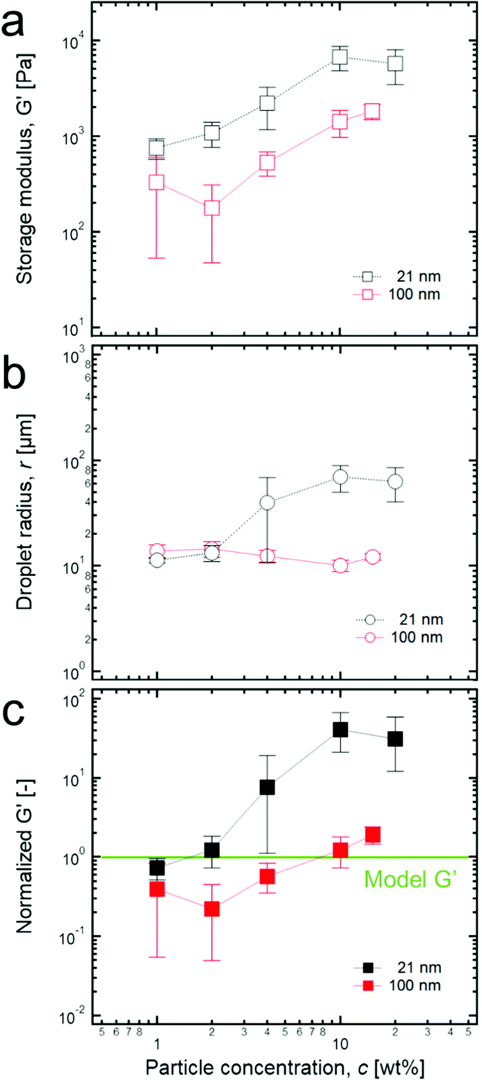 | ||
| Fig. 2 (a) Storage modulus of each HIPPE stabilized by two different sized TiO2 particles with various concentrations. (b) Droplet radius of each HIPPE sample with various particle concentrations. (c) Normalized G′ values with various particle concentrations. Here, from the empirical model for G′ of HIPEs, G′ = 1.769(γ/r)ϕ1/3(ϕ − 0.712), which is developed by Princen et al.,17 each value of the normalized G′s was calculated by dividing G′ by all the parameters in the right hand side of the equation. Here, normalized G′ = 0.086G′r, when ϕ and γ are 0.85 and 50 mN m−1, respectively, and the green line corresponds to 1. | ||
It should also be noted that there is a significant difference between each magnitude of the normalized G′ of the HIPPEs that are stabilized by two different TiO2 particles (Fig. 2c). Here, the value of the normalized G′ must be 1 when HIPPEs follow the model suggested by Princen et al.17 As shown in Fig. 2c, the values of the normalized G′ of HIPPEs, stabilized by 21 nm TiO2 particles are several tens of times greater than those of the model HIPEs, and this result is also in good agreement with previous studies for the HIPPEs.25,28–30 Furthermore, for up to 2 wt% of 21 nm particles, the value of the normalized G′ stays near 1; however, it increases sharply above 2 wt% and then saturates at 10 wt%. In contrast, for HIPPEs with 100 nm TiO2 particles, the normalized G's are almost equal to 1 or even less than 1 at low particle concentrations (≤4 wt%). Here, we believe that the relatively low stability of HIPPEs may result in a local destabilization of the HIPPE samples during the loading process onto the parallel palate, and this low stability can cause normalized G′ values of less than 1 with large errors, as shown in Fig. 2c. More details about the effect of the size of particles on the rheological properties are discussed later.
In order to properly explain the significantly large values of the normalized G′ of HIPPEs containing 21 nm TiO2 particles with a concentration of 4 wt% or more, we here consider two possible contributions; the interfacial elasticity of the 2-dimensional particle layer at the interface and the bulk elasticity of the continuous phase. The 2-dimensional rigid particle layer can make more elastic emulsions by disturbing the deformation of droplets, while the elasticity of a thin continuous phase where excess particles possibly form 3-dimensional structures, can also contribute to the significant increase of G′. To investigate these contributions, we measured the interfacial rheological properties of TiO2 particle layers at the interface and bulk rheological properties of the thin continuous phase. These results are explained in detail below.
3.2. Interfacial properties and their contribution to the HIPE elasticity
When colloidal particles are adsorbed at the interface, it is generally believed that the desorption energy of colloidal particles is much greater than kBT,8 even though this energy depends on the size and contact angle of the particles, thereby causing an irreversible adsorption of the particles. Due to this irreversible adsorption, colloidal particles easily form a dense layer at the interface and interfere with the deformation of the droplets, which plays an important role in determining the rheological properties of HIPPEs.30 When discussing the interfacial properties of a particle-laden interface, two different moduli are usually considered: the dilatational modulus and the shear modulus. The dilatational modulus is related to the isotropic expansion/compression of the interfacial area while the shear modulus represents the shear deformation, and there is still some debate as to which modulus is more relevant to the properties of emulsions. Nevertheless, we contend that the dilatational modulus of the 2D rigid particle layers mainly determine the elasticity of the Pickering emulsions according to previous work by Leal-Calderon et al.29 Here, they reported that a layer of proteins on the interface with a larger dilatational modulus could form HIPEs with a greater normalized G′.To effectively measure the dilatational modulus (Ed) of the 2D particle layer at the interface, we utilized the isotherm data of the TiO2 suspension with 20 wt%, as shown in Fig. S3 (ESI†). Using the Wilhelmy plate method, the isotherm was measured at the air–water interface rather than at the oil–water interface because the Wilhelmy plate is only applicable to the air–water interface. Instead, the measurement of the surface pressure of the TiO2 particle layer at the oil–water interface was conducted by a pendent drop method where water droplets containing 0.001–20 wt% of the particle concentration are suspended in the oil phase; however, the significantly low interfacial tension of the particle suspension cannot be measured via the pendent drop technique (Fig. S4, ESI†). Accordingly, here, the data of the interfacial tension between air and the aqueous particle suspension, rather than that of the oil–water interface, is utilized to effectively estimate the dilatational modulus of the particle layers because it has been reported that the isotherms of colloidal particles9,34–36 and proteins37,38 at the air–water interface are quite similar to that at the oil–water interface. For proteins, similar rheological properties of the protein layers have also been reported.37–39 Therefore, we believe that the isotherm data at the air–water interface effectively represents the behaviour of TiO2 particles at the oil–water interface under compression.
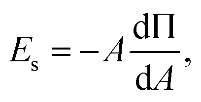
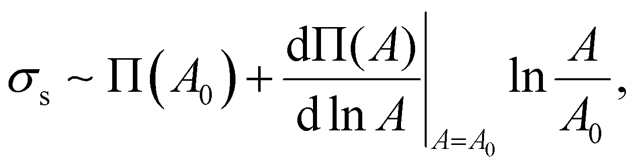
In order to effectively indicate the correlation between the dilatational modulus of the particle layers and the elasticity of the HIPPE, the following procedure is performed. First, the static compressional modulus (Es) can be calculated according to the surface pressure change with surface area A,
 | (1) |
 | (2) |
In particular, the isotherm (Fig. S3a, ESI†) indicates that the maximum surface pressure is ∼72 mN m−1, which is greater than the values of other colloidal particle suspensions,34,41–43 and the maximum compressional modulus is also as high as ∼80 mN m−1 (Fig. S3b, ESI†). Here, the elastic modulus of HIPEs can be calculated by dividing the interfacial energy (Ws) of droplets by their volume. The free energy of droplets can be obtained by the integration of surface stress (σs) with respect to surface area A,14,44
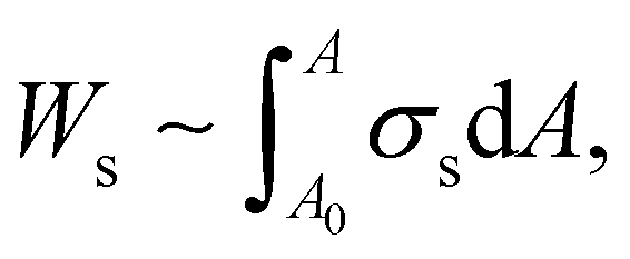 | (3) |
 | (4) |
 | (5) |
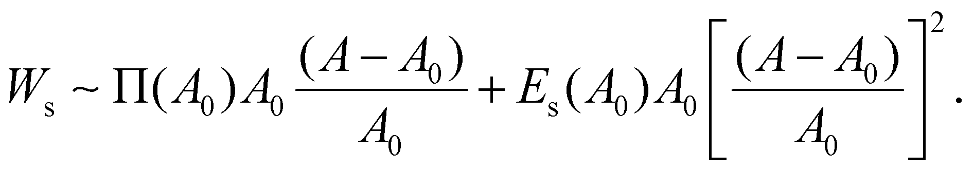
By assuming that the deformation of a droplet is very small compared to the original state (A − A0)/A0 ≪ 1, the second term for Ws can be negligible because the values of Es and Π are of a similar magnitude according to Fig. S3b (ESI†). Interestingly, even though the dilatational modulus of the particle layer can play an important role in determining the elastic modulus of HIPPEs, as shown in eqn (5), the surface pressure has a greater effect on the total interfacial energy, compared to the dilatational modulus. In contrast, Es can be crucial for determining G′, only if the value of Es is much greater than that of Π.14 Therefore, elastic modulus (G′) is written as:
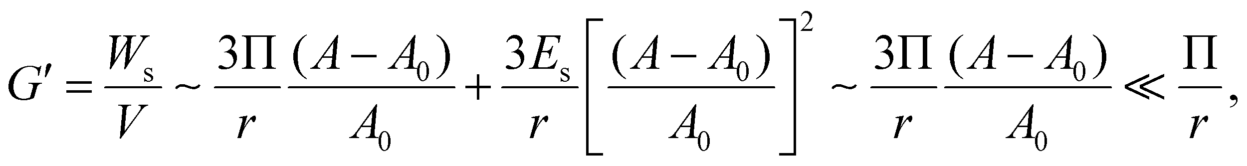 | (6) |
According to eqn (6), the elasticity of the HIPPE that is induced by the particle layer at the interface is much smaller than Π/r whose value is similar to G′ of the model HIPE, γ/r, as indicated in Fig. 3c. Therefore, the interfacial properties from the densely packed particle layer at the interface are not adequate for explaining the significantly high G′s of the HIPPEs with a relatively large concentration of TiO2. Furthermore, the experimental results, shown in Fig. 2, also supports this conclusion. As the concentration of 21 nm particles increases, the value of the normalized G′ increases significantly, even though the total interfacial area decreases. Therefore, the contribution from the bulk continuous phase would be a strong candidate for determining this extremely high G′.
 | ||
| Fig. 3 (a) Columnar model of hexagon shape droplets of HIPE with finite thickness of continuous phase film, h. The rhombic shaped unit cells are repeated almost infinitely. When the shear deformation (Δx) is applied to the unit cell, the summation of all the forces from the three clusters (1, 2, 3) and the surface tension becomes the shear stress. (b) A red line corresponds to the G′s of the model HIPPEs that contain the thin elastic film (∼3 μm) between droplets (∼50 μm). The black line is the normalized G′ data of G′ = 0.525(γ/r)ϕ1/2, which corresponds to the theoretical model suggested by Princen et al.15 When the elasticity of continuous phase film is large enough (>103 pa), a deviation between the two lines becomes significantly large. | ||
3.3. Theoretical model for the elasticity of HIPPEs
When the volume fraction of the dispersed phase of emulsions is high enough (generally, ϕ > 0.74), concentrated droplets formed within the continuous phase give rise to a significant elasticity because the energy stored in the droplets can be effectively transferred throughout the whole system. However, at relatively low volume fractions, the continuous phase which is usually a viscous liquid easily dissipates the stored energy, thereby creating the dominant G′′ over G′. Therefore, if the continuous phase possesses its own elasticity, it can be expected that the stored energy can transfer well in the emulsion system, regardless of its volume fraction, and this strongly suggests that the significant elasticity of the continuous phase can also affect the value of G′ along with the interfacial energy.To effectively check the contribution of the continuous phase to the G′ of emulsions, we propose a new theoretical model by modifying the cylindrical model that was developed by Princen et al.,15 as shown in Fig. S5 and S6 (ESI†). In the case of HIPE systems, the continuous phase between adjacent distorted droplets is very thin, and its average thickness can be roughly calculated by assuming that the shape of droplets is cubic or spherical, thereby resulting in 0.6–6 μm of the thickness, which is much thinner than the radius of the droplets (10–50 μm). The detailed calculation for the thickness is given in the supplementary information (Fig. S7, ESI†). Here, we consider it as a thin film surrounding the hexagonal columnar droplets with a constant thickness, as shown in Fig. 3a. Furthermore, we also assume that the same structure of the unit cell (Fig. 3a) is repeated almost infinitely, and the calculations for shear strain and stress in the unit cell effectively represent the properties of the whole system.
Specifically, the shear strain (γ) is calculated by dividing the deformation (Δx) that results in the change in the angle α by the vertical length of the unit cell (Fig. 3a),
 | (7) |
The shear stress (τ) can also be calculated by dividing the sum of all the forces (F) exerted on the unit cell (Fig. 3a) by the horizontal length of the unit cell,
 | (8) |
When calculating the total force (F), only forces in the same direction as the strain are considered because others are eliminated due to the symmetry, and this gives
 | (9) |
Then, G′ of the columnar model system is given by the ratio of the shear stress to the shear strain, and all the detailed procedures for deriving the above expressions is described in the ESI† (Fig. S5 and S6).
Based on this columnar model, the contribution of the continuous phase on the G′ seems to be well explained in Fig. 3b. The black line in Fig. 3b depicts the theoretical G′ data of the Princen model with a surface tension of 50 mN m−1 and a droplet radius of 50 μm while the red line corresponds to the G′ data of the proposed model. These two lines are quite similar until a film elasticity of ∼103 pa, but deviation starts to occur beyond this point and becomes much greater as the film elasticity increases. Here, it is difficult to accurately measure the elasticity of particle suspension thin films using parallel plate rheometry due to several technical difficulties: 1. It is tremendously challenging to achieve a few micron-gaps between parallel plates: 2. The slip effect between the plate and the particle suspension is quite large in this thin gap. Furthermore, this model cannot precisely predict the G′ value of the HIPEs from the value of the elasticity of the film because dispersed droplets are polyhedral with various shapes, rather than just simple hexagonal columns. Nevertheless, this simple columnar model ensures that a more elastic continuous phase creates a HIPE system with a greater G′, and this strongly suggests that the significant elasticity of the continuous phase can be the origin of the normalized G′ whose value is greater than 1.
Furthermore, although it is extremely challenging to measure the rheological properties of the actual structure of colloidal particles in the thin continuous phase, the influence of these structures on the rheological properties of HIPPEs can be evaluated indirectly. When an o/w HIPPE is dried for several hours, the water in the continuous phase can evaporate almost completely, and the remaining dispersed phase is possibly surrounded by much more particle aggregates than at the initial stage, which results in even more connections between droplets. The linear viscoelastic properties of HIPPE where 20 wt% of 21 nm TiO2 particles are initially dispersed in the continuous phase are then measured, G′ ∼ 20000 Pa (Fig. S8, ESI†) and as a result, it is confirmed that this particle structure can be highly elastic. This significant increase in G′ may also occur as the volume fraction of the dispersed phase increases due to the continuous evaporation of water. However, even if the volume fraction of the dispersed phase changes from 0.85 to 0.99 due to evaporation, G′ only increases by 2.12 times according to the Princen model.17 Therefore, we believe that the extremely large value of G′ (∼20000 Pa) mainly originates from the elastic structure of particles surrounding the dispersed phase.
3.4. Rheology of colloidal suspensions under geometric confinement
The above theoretical model confirms that the significant elasticity of the HIPPE might originate from the elastic property of the continuous film. Here, the continuous phase is the TiO2 suspension, and the bulk rheological properties of the TiO2 suspensions with two different sizes, 21 nm and 100 nm, are given in Fig. S9 (ESI†). The linear viscoelastic measurements in the whole range of particle concentrations confirm that 21 nm TiO2 suspensions are viscous liquids (Fig. S9a, ESI†) while 100 nm TiO2 suspensions behave like elastic solids (Fig. S9b, ESI†); however, their G′s are not large enough to induce the significantly large elasticity of the HIPPEs. Therefore, it is necessary to clarify the origin of the elasticity of thin TiO2 suspensions.For 21 nm TiO2 particle suspensions, their aggregate size appears as ∼300 nm when measured with DLS after dilution to 0.005 wt% (Fig. S10, ESI†). This suggests that TiO2 particles attract each other, so that they can form aggregates in the continuous phase. This also strongly suggests that their size can be even greater than 300 nm in the concentrations of particles for preparing HIPPEs. Furthermore, the continuous phase of HIPPEs with 85% of the volume fraction of the dispersed phase gives a very thin layer between droplets, which is calculated as a thickness of 2–6 μm, according to the simple calculation found in the supplementary information, Fig. S7 (ESI†). In more realistic HIPE systems where plateau borders appear clearly, the film thickness would be much thinner than the calculated value. Here, since a length scale of the continuous phase thickness can be comparable to the flocculation size of particles, adjacent droplets might be well connected by the particle structures if the number of particles is sufficient in the continuous phase, thereby causing a greater normalized G′ due to the elasticity of the particle structures.
Thus, the number of residual particles in the continuous phase can be a key parameter to determine the value of a normalized G′, and to confirm this, we measured the residual particle concentration. As a result (Fig. 4a), when the initial concentration of particles increases, the residual concentrations for both 21 nm TiO2 particles and 100 nm TiO2 particles seems to increase gradually. As for 21 nm particles, the residual concentration suddenly increases above 4 wt%: a tendency that agrees well with that of the normalized G′, as shown in Fig. 2c. This strongly suggests that the connected particle structures, possibly formed at relatively high concentrations, can be responsible for extremely high normalized G′s. In contrast, the residual concentration for 100 nm TiO2 particles increases monotonically when increasing the initial concentration.
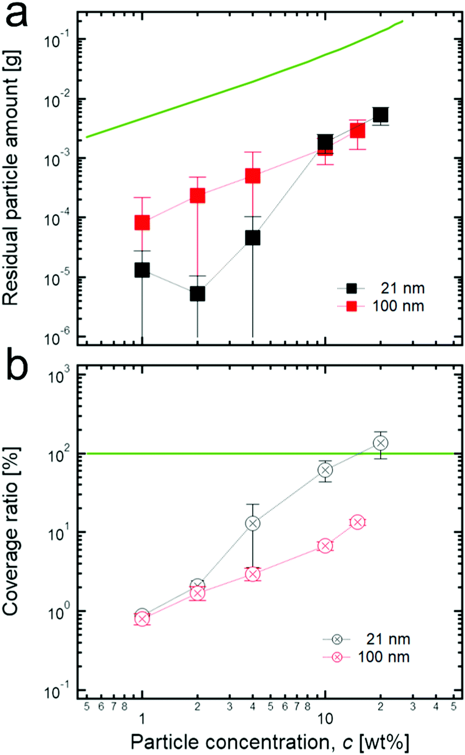 | ||
| Fig. 4 (a) Residual particle concentrations in the continuous phase of each HIPE sample. The green line indicates the initial concentrations (the bottom axis) of colloidal particles before emulsification. (b) The surface coverage ratio of colloidal particles to the surface of droplets in the HIPPEs when varying the particle concentration. This can be obtained by subtracting the residual particle concentration in the continuous phase from the initial particle concentration. In the case of 21 nm TiO2 particles, 100% coverage ratio (green line) is reached when 20 wt% is added while it cannot be achieved even at the highest concentration (15 wt%) in the case of 100 nm TiO2 particles. | ||
The residual concentration values are much smaller than the values of each initial concentration of particles, as shown in Fig. 4a. Specifically, the residual concentration for 21 nm particles is several hundreds of times lower than the initial concentration at a relatively low concentration (≤4 wt%) while it has less difference (∼one order of magnitude) at the high concentration (≥10 wt%). In addition, the residual concentration of 100 nm particles is tens of times lower than each initial concentration in the entire concentration region. Here, even though the difference of magnitude between the residual concentration of 21 nm particles and the initial concentration is relatively small at the high concentration region, we believe that the residual concentration values are still underestimated at this region because most particles which form the connected structure between adjacent droplets can be rarely detached from the interface even during the dilution process (see the Materials and methods section); therefore, they appear as adsorbed ones, not residual ones. It can also be seen that the large flocculated structures of particles are still attached on the surface of droplets after the dilution process, as shown in Fig. S2 (ESI†).
Furthermore, according to the size information of particle aggregates at extremely diluted concentrations (300 nm for 21 nm and 400 nm for 100 nm particles, see the Materials and methods section), the coverage ratio of particles to the droplet surface can be roughly calculated by assuming that particle aggregates are preferentially located at the interface, and at the interface, they are hexagonally close-packed with a 90° contact angle (Fig. 4b). As shown in Fig. 4b, at a relatively low initial concentration of 21 nm particles, a low coverage ratio is observed, whereas the coverage ratio approaches 100% at a high initial concentration (≥10 wt%). This strongly indicates that at a high concentration, more particles may prefer to stay in the bulk phase, thereby possibly resulting in the formation of connected particle structures between droplets. In contrast, the samples with 100 nm TiO2 particles show a relatively low coverage ratio, even at a high initial concentration, suggesting that it might be difficult to form connected structures in the continuous phase because of an insufficient number of particles. This tendency is also in good agreement with the previous result for the normalized G′.
Even though a small number of particles in the continuous phase might cause a lack of connected structures between dispersed droplets, the formation of the connected structure can be facilitated when the tendency for the particles to attract each other increases. To do so, various concentrations of salts are added in particle suspensions for controlling the attractive interaction between particles. As the concentration of salt increases, a charge repulsion between particles decreases; thus, TiO2 particles can form larger aggregates which is indirectly confirmed by measuring the sedimentation time of particle suspensions (Fig. S11, ESI†). In particular, as indicated in Fig. 5, the addition of both sodium chloride and calcium chloride salts to HIPPEs with 4 wt% of 100 nm TiO2 particles significantly alters the value of the normalized G′ while in the case of 21 nm TiO2 particles with 4 wt%, the value of the normalized G′ remains almost constant because the number of particles might already be sufficient in the continuous phase to form the connected structures. Furthermore, calcium chloride that provides divalent cations is more effective to screen net negative charges compared to sodium chloride whose cations are monovalent, so that larger flocculated structures are expected, and this result is also supported by the result for the normalized G′ in Fig. 5b. In addition to the G′ result, the droplet size can be also changed by adding salts. As shown in Fig. S12 (ESI†), a gradual increase in the droplet size seems to occur when the concentration of calcium chloride–salt increases from 0 to 100 mM. According to this, the larger particle aggregates might be responsible for forming larger droplets, which is also in good agreement with the result in Fig. 2b, where the droplet size increases with the concentration of 21 nm TiO2 particles.
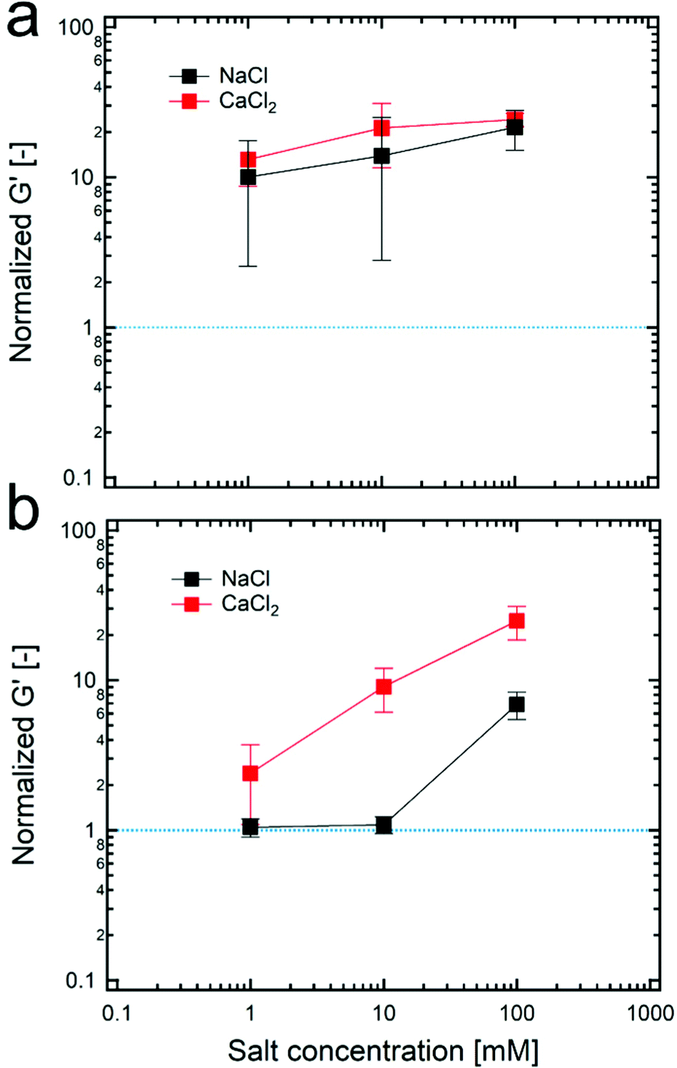 | ||
| Fig. 5 The normalized G′ of HIPPEs, stabilized with (a) 21 nm TiO2 particles and (b) 100 nm TiO2 particles, respectively with varying concentration of salts. Here, the concentration of TiO2 particles in the continuous phase and the volume fractions of dispersed droplets were fixed to 4 wt% and 85%, respectively for all HIPPE samples. | ||
4. Conclusions
In this paper, we successfully achieved high internal phase Pickering emulsions (HIPPEs) stabilized by two different sized TiO2 particles, 21 nm and 100 nm, by varying the particle concentration in the continuous phase from 1 wt% to 20 wt% and measuring the rheological properties of HIPPEs using a parallel plate rheometer. With this study, we confirmed that HIPPEs with 21 nm TiO2 particles have large elasticity values over 4 wt% of the particle concentration, and to clarify this, we considered two interfacial rheological property contributions of the densely packed particle layer at the interface and the bulk rheological properties of the continuous phase that contains many particles.To elucidate the effect of interfacial properties of particle layers, we first measured the dilatational modulus of the particle layers which may be a crucial factor for the elasticity of HIPPEs using isotherms of 2-D particle layers, and the simple calculation for the elastic modulus from the surface free energy of droplets enabled us to conclude that the interfacial properties cannot determine a large elasticity of HIPPEs. Therefore, we then developed a simple theoretical model which strongly indicates that a significant bulk elasticity of the thin film between the droplets causes the great elasticity of HIPPEs. This finding was supported by the experimental measurement of the high elasticity of aggregated structures of particles. Furthermore, we measured the concentration of residual particles in the thin continuous phase, and we also contend that excess particles in the continuous phase can form aggregates whose sizes are comparable to the thickness of the thin continuous film, so that well connected bulk structures can be formed between droplets. By adding salts to the continuous phase with various concentrations, which resulted in changing the size of the flocculated particle structures, we also demonstrated that the presence of elastic structures which connect the dispersed droplets well are the primary origin of the significantly greater value of elasticity.
Conflicts of interest
There are no conflicts to declare.Acknowledgements
This work was supported by the Basic Science Research Program through the National Research Foundation of Korea (NRF-2019R1F1A1052133, NRF-2020R1F1A1068217, and NRF-2021R1A2C2009859) and a grant of the Korea Health Technology R&D Project through the Korea Health Industry Development Institute (KHIDI), funded by the Ministry of Health & Welfare, Republic of Korea (Grant No. HP20C0006030021).Notes and references
- J. M. Williams, Langmuir, 1991, 7(7), 1370–1377 CrossRef CAS.
- V. V. Dhanuka, J. L. Dickson, W. Ryoo and K. P. Johnston, J. Colloid Interface Sci., 2006, 298(1), 406–418 CrossRef CAS.
- I. Pulko and P. Krajnc, Macromol. Rapid Commun., 2012, 33(20), 1731–1746 CrossRef CAS.
- L. L. C. Wong, P. M. Baiz Villafranca, A. Menner and A. Bismarck, Langmuir, 2013, 29(20), 5952–5961 CrossRef CAS PubMed.
- A. Menner, V. Ikem, M. Salgueiro, M. S. P. Shaffer and A. Bismarck, Chem. Commun., 2007, 4274–4276 RSC.
- I. Akartuna, A. R. Studart, E. Tervoort and L. J. Gauckler, Adv. Mater., 2008, 20, 4714–4718 CrossRef CAS.
- V. O. Ikem, A. Menner and A. Bismarck, Angew. Chem., Int. Ed., 2008, 47, 8277–8279 CrossRef CAS PubMed.
- B. P. Binks, Curr. Opin. Colloid Interface Sci., 2002, 7, 21–41 CrossRef CAS.
- T. S. Horozov and B. P. Binks, Angew. Chem., 2006, 118, 787–790 CrossRef.
- P. A. Kralchevsky and N. D. Denkov, Curr. Opin. Colloid Interface Sci., 2001, 6, 383–401 CrossRef CAS.
- C. Monteux, J. Kirkwood, H. Xu, E. Jung and G. G. Fuller, Phys. Chem. Chem. Phys., 2007, 9, 6344 RSC.
- M. Cui, T. Emrick and T. P. Russell, Science, 2013, 342, 460–463 CrossRef CAS PubMed.
- V. Poulichet and V. Garbin, Proc. Natl. Acad. Sci. U. S. A., 2015, 112, 5932–5937 CrossRef CAS.
- P. J. Beltramo, M. Gupta, A. Alicke, I. Liascukiene, D. Z. Gunes, C. N. Baroud and J. Vermant, Proc. Natl. Acad. Sci. U. S. A., 2017, 201705181 Search PubMed.
- H. M. Princen, J. Colloid Interface Sci., 1983, 91, 160–175 CrossRef CAS.
- H. M. Princen, J. Colloid Interface Sci., 1985, 105(1), 150–171 CrossRef CAS.
- H. M. Princen and A. D. Kiss, J. Colloid Interface Sci., 1986, 112, 427–437 CrossRef CAS.
- T. G. Mason, J. Bibette and D. A. Weitz, Phys. Rev. Lett., 1995, 75, 2051–2054 CrossRef CAS PubMed.
- T. G. Mason, J. Bibette and D. A. Weitz, J. Colloid Interface Sci., 1996, 179(2), 439–448 CrossRef CAS.
- T. G. Mason, M. D. Lacasse, G. S. Grest, D. Levine, J. Bibette and D. A. Weitz, Phys. Rev. E: Stat. Phys., Plasmas, Fluids, Relat. Interdiscip. Top., 1997, 56, 3150–3166 CrossRef CAS.
- P. Rajinder, Colloid Polym. Sci., 1999, 277, 583–588 CrossRef.
- R. G. Larson, The structure and rheology of complex fluids, 1999, vol. 150 Search PubMed.
- J. G. Oldroyd, Proc. R. Soc. London, Ser. A, 1953, 218, 1132 Search PubMed.
- L. Bressy, P. Hébraud, V. Schmitt and J. Bibette, Langmuir, 2003, 19(3), 598–604 CrossRef CAS.
- S. Arditty, V. Schmitt, J. Giermanska-Kahn and F. Leal-Calderon, J. Colloid Interface Sci., 2004, 275(2), 659–664 CrossRef CAS PubMed.
- M. Kaganyuk and A. Mohraz, Soft Matter, 2017, 13, 2513–2522 RSC.
- K. Kim, S. Kim, J. Ryu, J. Jeon, S. G. Jang, H. Kim, D. G. Gweon, W. Bin Im, Y. Han, H. Kim and S. Q. Choi, Nat. Commun., 2017, 8(1), 1–8 CrossRef CAS PubMed.
- M. Kaganyuk and A. Mohraz, J. Colloid Interface Sci., 2019, 540, 197–206 CrossRef CAS PubMed.
- T. D. Dimitrova and F. Leal-Calderon, Adv. Colloid Interface Sci., 2004, 108, 49–61 CrossRef PubMed.
- S. Arditty, V. Schmitt, F. Lequeux and F. Leal-Calderon, Eur. Phys. J. B, 2005, 44, 381–393 CrossRef CAS.
- L. Maurice, R. A. Maguire, A. B. Schofield, M. E. Cates, P. S. Clegg and J. H. J. Thijssen, Soft Matter, 2013, 9, 7757 RSC.
- S. Tcholakova, N. D. Denkov and A. Lips, Phys. Chem. Chem. Phys., 2008, 10, 1608–1627 RSC.
- W. J. Tseng and K. C. Lin, Mater. Sci. Eng., A, 2003, 355, 186–192 CrossRef.
- M. Safouane, D. Langevin and B. P. Binks, Langmuir, 2007, 23(23), 11546–11553 CrossRef CAS PubMed.
- R. Aveyard, J. H. Clint, D. Nees and V. N. Paunov, Langmuir, 2000, 16, 1969–1979 CrossRef CAS.
- S. Reynaert, P. Moldenaers and J. Vermant, Langmuir, 2006, 22, 4936–4945 CrossRef CAS PubMed.
- A. Williams and A. Prins, Colloids Surf., A, 1996, 114, 267–275 CrossRef CAS.
- J. Benjamins, J. Lyklema and E. H. Lucassen-Reynders, Langmuir, 2006, 22(14), 6181–6188 CrossRef CAS PubMed.
- S. Reynaert, P. Moldenaers and J. Vermant, Phys. Chem. Chem. Phys., 2009, 9, 6463–6475 RSC.
- A. J. Mendoza, E. Guzmán, F. Martínez-Pedrero, H. Ritacco, R. G. Rubio, F. Ortega, V. M. Starov and R. Miller, Adv. Colloid Interface Sci., 2014, 206, 303–319 CrossRef CAS PubMed.
- V. B. Fainerman, V. I. Kovalchuk, E. H. Lucassen-Reynders, D. O. Grigoriev, J. K. Ferri, M. E. Leser, M. Michel, R. Miller and H. Möhwald, Langmuir., 2006, 22(4), 1701–1705 CrossRef CAS PubMed.
- C. Monteux, E. Jung and G. G. Fuller, Langmuir., 2007, 23(7), 3975–3980 CrossRef CAS PubMed.
- S. Razavi, K. D. Cao, B. Lin, K. Y. C. Lee, R. S. Tu and I. Kretzschmar, Langmuir, 2015, 31(28), 7764–7775 CrossRef CAS PubMed.
- K. D. Danov, D. N. Petsev, N. D. Denkov and R. Borwankar, J. Chem. Phys., 1993, 99(9), 7179–7189 CrossRef CAS.
Footnote |
| † Electronic supplementary information (ESI) available. See DOI: 10.1039/d1sm01338f |
| This journal is © The Royal Society of Chemistry 2022 |