
 Open Access Article
 This Open Access Article is licensed under a Creative Commons Attribution-Non Commercial 3.0 Unported Licence
Electrocatalytic reduction of protons to dihydrogen by the cobalt tetraazamacrocyclic complex [Co(N4H)Cl2]+: mechanism and benchmarking of performances†‡
Cheng-Bo
Li§
ab,
Andrew J.
Bagnall§
 bc,
Dongyue
Sun
b,
Julia
Rendon
bd,
Matthieu
Koepf
b,
Serge
Gambarelli
d,
Jean-Marie
Mouesca
d,
Murielle
Chavarot-Kerlidou
b and
Vincent
Artero
*b
bc,
Dongyue
Sun
b,
Julia
Rendon
bd,
Matthieu
Koepf
b,
Serge
Gambarelli
d,
Jean-Marie
Mouesca
d,
Murielle
Chavarot-Kerlidou
b and
Vincent
Artero
*b
aKey Laboratory of Synthetic and Natural Functional Molecule of the Ministry of Education, The Energy and Catalysis Hub, College of Chemistry and Materials Science, Northwest University, Xi'an 710127, China
bUniv. Grenoble Alpes, CNRS, CEA, IRIG, Laboratoire de Chimie et Biologie des Métaux, 17 Rue des Martyrs, F-38054 Grenoble, Cedex, France. E-mail: vincent.artero@cea.fr
cÅngström Laboratory, Department of Chemistry, Uppsala University, SE75120 Uppsala, Sweden
dUniv. Grenoble Alpes, CNRS, CEA/IRIG-SyMMES, 17 Rue des Martyrs, F-38054 Grenoble, Cedex, France
First published on 22nd November 2021
Abstract
The cobalt tetraazamacrocyclic [Co(N4H)Cl2]+ complex is becoming a popular and versatile catalyst for the electrocatalytic evolution of hydrogen, because of its stability and superior activity in aqueous conditions. We present here a benchmarking of its performances based on the thorough analysis of cyclic voltammograms recorded under various catalytic regimes in non-aqueous conditions allowing control of the proton concentration. This allowed a detailed mechanism to be proposed with quantitative determination of the rate-constants for the various protonation steps, as well as identification of the amine function of the tetraazamacrocyclic ligand to act as a proton relay during H2 evolution.
Molecular cobalt complexes are popular and versatile catalysts for the electrocatalytic evolution of hydrogen.1–5 Recently, the cobalt complex [Co(N4H)Cl2]+ (Cat1, Fig. 1) based on the tetraazamacrocyclic 2,12-dimethyl-3,7,11,17-tetraazabicyclo[11.3.1]heptadeca-1(17),2,11,13,15-pentaene ligand,6 described by Karn and Busch in 1966, has received increased interest7–9 namely because this catalyst proves active and stable for the evolution of H2 from fully aqueous solutions.7–17 A study carried out under homogeneous conditions using chemical reductants or photochemical activation confirmed the superior activity of Cat1 in fully aqueous media,18 and X-ray absorption spectroscopic monitoring of a homogeneous photocatalytic system for H2 evolution based on Cat1 indicated an ECEC mechanism (E = monoelectronic electrochemical reduction, C = protonation step) starting from the bisaqua Co(II) complex.13,14 However, very few metrics are currently available to benchmark the catalytic activity of this compound. Cat1 was included in a benchmarking study for H2-evolving electrocatalysts carried out in aqueous electrolyte19 but under quite acidic conditions likely to induce reductive degradation of the ligand during the test and formation of metallic particles responsible for the observed HER activity.20,21 To gain quantitative information on the H2 evolution mechanism mediated by Cat1, we therefore revisited the non-aqueous conditions investigated by Lau and coworkers,22 where it is easier to control the concentration and chemical potential of protons.23
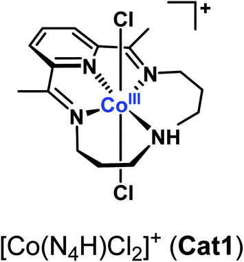 | ||
| Fig. 1 Structure of Cat1. | ||
The cyclic voltammogram of Cat1 (perchlorate salt) in CH3CN (with 0.1 M nBu4NBF4, Fig. 2 and S1‡) displays two quasi-reversible systems at −0.47 V (ΔEp = 92 mV) and −0.96 V (ΔEp = 86 mV) vs. Fc+/Fc, corresponding to the CoIII/II and CoII/I redox processes, respectively, based on previous literature. Of note, we will formally use the CoI notation throughout this article, while the electronic state could also correspond to a reduced N4H ligand (π-radical anion) antiferromagnetically coupled to a low-spin Co(II) ion.24 A third ligand-centered process is observed at −1.89 V (ΔEp = 69 mV) vs. Fc+/Fc.22 Upon addition of p-cyanoanilinium tetrafluoroborate (pKa = 7.0 in CH3CN)25 acting as a proton source, a catalytic wave develops on the top of the CoII/I wave as previously described.22 This electrocatalytic behavior corresponds to H2 evolution with >90% faradaic yield22 and nicely mirrors the one observed for Cat1 in mildly acidic aqueous solution.11,13,22 The addition of stronger acids such as HBF4·Et2O or CF3SO3H also triggers H2 evolution catalysis but is detrimental to the stability of Cat1 at high concentration. Cat1 is unable to catalyze the reduction of acids with higher pKa values, starting with p-toluenesulfonic acid (pKa = 8.3 in CH3CN).26
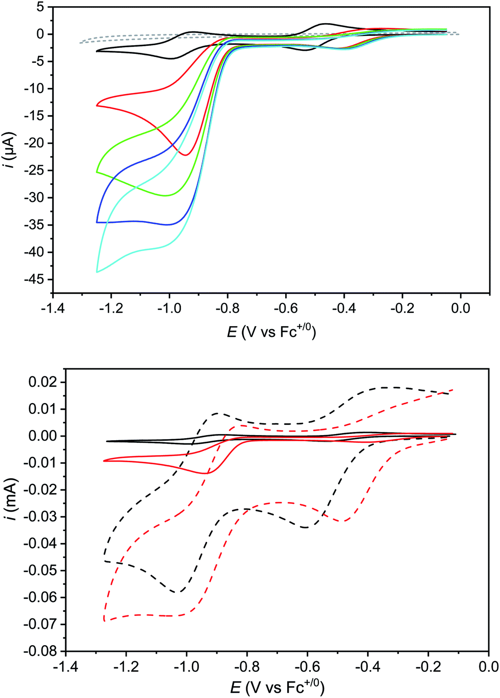 | ||
| Fig. 2 Top: cyclic voltammograms of Cat1 (0.5 mM) in CH3CN (+0.1 M nBu4NBF4) recorded at a glassy carbon electrode (1.6 mm diameter) in the absence (black trace) and in the presence of 5.0 (red trace), 10.0 (green trace), 12.5 (navy trace) and 15.0 mM (cyan trace) p-cyanoanilinium tetrafluoroborate; scan rate: 100 mV s−1. A control voltammogram of 15 mM p-cyanoanilinium tetrafluoroborate without Cat1 (gray dashed trace) is shown for comparison; bottom: cyclic voltammograms of Cat1 (0.5 mM) in CH3CN (+0.1 M nBu4NBF4) recorded at a glassy carbon electrode in the absence (black) and in the presence (red) of 5 mM p-cyanoanilinium tetrafluoroborate; scan rate: 0.1 (solid) and 10 V s−1 (dashed). See Fig. S5‡ for control voltammograms without catalyst under similar conditions. | ||
Noteworthily, the addition of acid also affects the CoIII/II system, which shifts to more positive potentials and partly loses reversibility. 1H NMR experiments confirmed that the CoIII form of Cat1 is not protonated under these conditions (Fig. S2‡), neither does p-cyanoaniline coordinate to any of the CoIII, CoII and CoI states of Cat1 (Fig. S3‡) in the absence of acid. However, when 5 equivalents of p-cyanoanilinium tetrafluoroborate is added to an electrochemically-generated solution of the CoII form of Cat1, the EPR signal is significantly changed, from a broad signal centered at g1 = 2.240, g2 = 2.130 and g3 = 2.004 to a better resolved spectrum characteristic for a low spin d7 (S = ½) electronic configuration of Co (Fig. 3). It furthermore displays a 5-line superhyperfine structure with an intensity ratio of 1![[thin space (1/6-em)]](https://www.rsc.org/images/entities/char_2009.gif) :2:3:2:1 and a coupling constant of 45 Hz in line with the coordination of two equivalent nitrogen-based ligands. Of note, a similar behavior was observed when the CoII form of Cat1 was prepared by chemical reduction with cobaltocene instead of exhaustive bulk electrolysis (Fig. S4‡). No such change is observed when p-cyanoaniline is added (Fig. S4‡). When HBF4·Et2O is used as proton source instead of p-cyanoanilinium tetrafluoroborate, this superhyperfine structure is changed to a 3-line structure with a coupling constant of 40 Hz (Fig. 3), suggesting the coordination of a single nitrogen-based axial ligand, CH3CN being the only plausible one under these conditions. In the former case, coordination of CH3CN and p-cyanoanilinium (or p-cyanoaniline generated in situ upon protonation of the complex) can be considered without being possible to discriminate one from the other at the EPR level. Taken all together, these observations suggest (i) protonation of the ligand in Cat1 occurs upon reduction from the CoIII to the CoII state in the presence of acid; (ii) at the same time, chloride axial ligands are displaced for nitrogen ligands; (iii) the nature and number of axial ligands depend on the nature of the acid employed. It should also be underlined that the binding of one vs. two ligands in the cobalt + II oxidation state likely depends on a subtle balance of their donating ability, as previously stated for Cat1 (ref. 11) and also found for cobaloximes and related cobalt diimine–dioxime complexes.27–30 A possible structure of CoIILH, in line with a previous proposition,13 is shown in Scheme 1.
:2:3:2:1 and a coupling constant of 45 Hz in line with the coordination of two equivalent nitrogen-based ligands. Of note, a similar behavior was observed when the CoII form of Cat1 was prepared by chemical reduction with cobaltocene instead of exhaustive bulk electrolysis (Fig. S4‡). No such change is observed when p-cyanoaniline is added (Fig. S4‡). When HBF4·Et2O is used as proton source instead of p-cyanoanilinium tetrafluoroborate, this superhyperfine structure is changed to a 3-line structure with a coupling constant of 40 Hz (Fig. 3), suggesting the coordination of a single nitrogen-based axial ligand, CH3CN being the only plausible one under these conditions. In the former case, coordination of CH3CN and p-cyanoanilinium (or p-cyanoaniline generated in situ upon protonation of the complex) can be considered without being possible to discriminate one from the other at the EPR level. Taken all together, these observations suggest (i) protonation of the ligand in Cat1 occurs upon reduction from the CoIII to the CoII state in the presence of acid; (ii) at the same time, chloride axial ligands are displaced for nitrogen ligands; (iii) the nature and number of axial ligands depend on the nature of the acid employed. It should also be underlined that the binding of one vs. two ligands in the cobalt + II oxidation state likely depends on a subtle balance of their donating ability, as previously stated for Cat1 (ref. 11) and also found for cobaloximes and related cobalt diimine–dioxime complexes.27–30 A possible structure of CoIILH, in line with a previous proposition,13 is shown in Scheme 1.
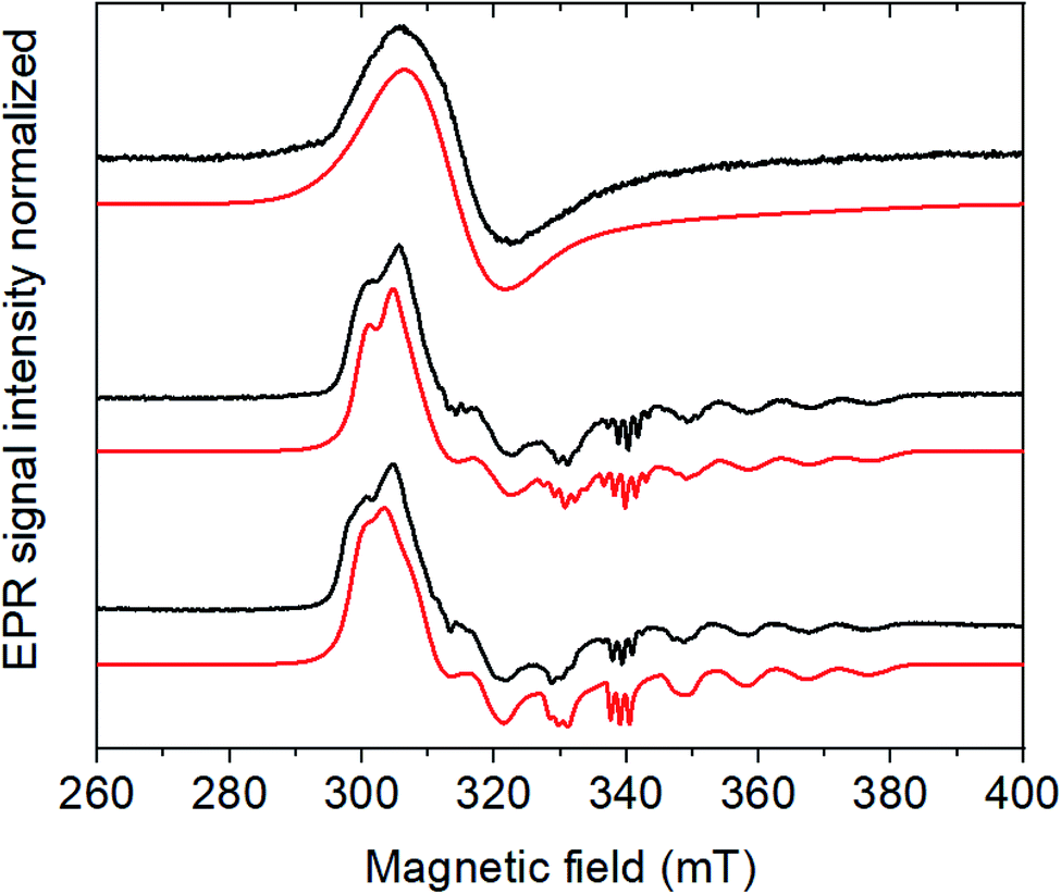 | ||
| Fig. 3 CW X-band EPR spectra (9.65 GHz) of the electrochemically generated CoII form of Cat1 (0.5 mM) as prepared (top), with 5 eq. of the acids p-cyanoanilinium tetrafluoroborate (middle), HBF4 (bottom) and their respective simulations in red. Experimental conditions: 30 K, 1 mW microwave power, 1600 G field sweep. Simulation parameters are reported in Table S1.‡ | ||
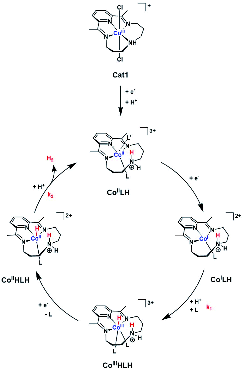 | ||
| Scheme 1 Proposed ECEC mechanism for H2 evolution mediated by Cat1. L and L′ indicate acetonitrile or p-cyanoaniline. | ||
Although the formation of the protonated CoII derivative of Cat1 falls into the proton-coupled electron transfer classification, the cathodic peak potential does not follow the increase of 29 mV per decade of acid concentration expected for an irreversible EC process with a fully displaced protonation equilibrium (e.g. in the pure kinetic KP zone);31 rather the cathodic peak potential rapidly shifts to a new value upon addition of acid and then keeps this value unchanged upon further addition (Fig. 2). This behavior is characteristic of the extraordinary kinetic (KE) zone,31 with fast protonation of the CoII species so that, even with few equivalents of acid added, the new wave is observed at a potential close to the apparent standard potential of the CoIII/CoIILH couple, thus with a ∼250 mV shift compared to the original CoIII/CoII couple. Recording the cyclic voltammograms at a significantly higher scan rate (10 V s−1) did not allow approaching the pure kinetic KP zone although a slightly more progressive evolution of the cathodic peak potential was observed with an increase of ∼200 mV per decade of acid concentration (Table S2‡). Simulations using the DigiElch software allowed to reproduce the potential shift of such an EC process at both 0.1 and 10 mV s−1 using a protonation equilibrium constant higher than 104 and a bimolecular protonation rate of 107 mol−1 L s−1, suggesting that the amine moiety can potentially act as a proton relay during catalysis.32
Protonation of the CoII state should also alter the standard potential of the CoII/CoI couple. At 100 mV s−1, this redox process is hidden by the catalytic wave it triggers. However, measuring cyclic voltammograms at 10 V s−1 enabled the catalysis to be outrun and a reversible wave to be recovered centred at −0.89 V vs. Fc+/Fc (Fig. 2 bottom) that likely corresponds to the actual CoIILH/CoILH couple responsible for catalysis. Remarkably, raising acid concentration, we found that catalysis proceeds under pure kinetic conditions, where a catalytic current plateau, independent of the scan rate, is observed (Fig. 4) because substrate consumption is negligible (pure kinetic KS zone).31,33 Under these conditions, the mid-wave potential of the catalytic process is found at −0.87 V vs. Fc+/Fc. Varying the catalyst concentration for a given acid concentration showed a linear dependence of the catalytic current with the catalyst concentration (Fig. S6‡). The catalytic plateau current also linearly varies with the acid concentration (Fig. S7‡).
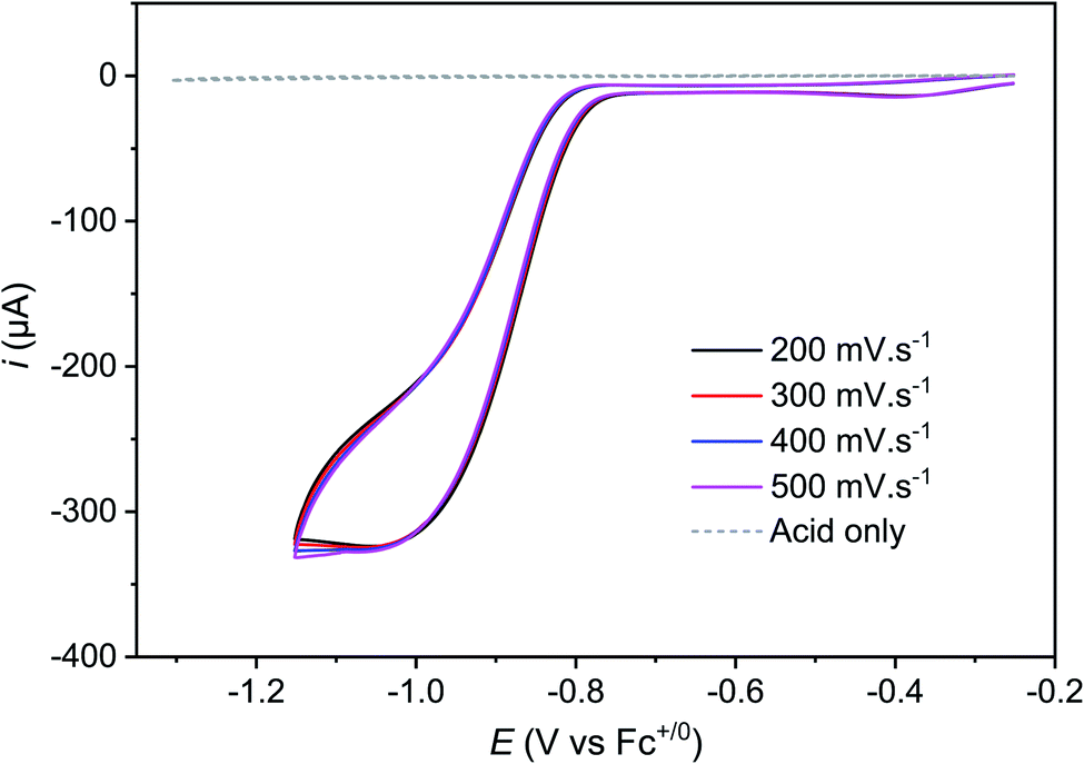 | ||
| Fig. 4 Cyclic voltammograms of Cat1 (1.6 mM) in CH3CN (+0.1 M nBu4NBF4) recorded at a glassy carbon electrode (1.6 mm diameter) in the presence of 60 mM p-cyanoanilinium tetrafluoroborate at various scan rates, scan rate ranging from 200 to 500 mV s−1 and with ohmic drop compensation. A control voltammogram of 60 mM p-cyanoanilinium tetrafluoroborate without Cat1 at 100 mV s−1 is shown for comparison. | ||
Together these data are consistent with a mechanism for H2 evolution catalyzed by Cat1 following an ECEC reaction scheme (Scheme 1), where E and C stand for electrochemical steps and chemical (i.e. protonation) steps and with the second reduction occurring at a potential more positive to that of the first one: reduction of the protonated CoII (CoIILH) state yields CoILH, which is further protonated to yield the CoIIIHLH species. Further reduction of this derivative then produces the CoII hydride CoIIHLH species that is further protonated to evolve H2 and regenerate the starting CoIILH complex. Some of the distorded geometries displayed in Scheme 1 for transient intermediates involved in the catalytic cycle are approximate and we do realize that they do not correspond to ideal geometries for coordination complexes with corresponding electronic structures. Protonation of the amine residue of the macrocyclic ligand namely generates an ammonium moiety unable to coordinate the cobalt center, though with significant steric hindrance preventing for example the adoption of a perfect square planar (or octahedral) geometry favored by the d8 (or d6) configuration in the CoILH (or CoIIIHLH) species, as demonstrated for the unprotonated CoI (ref. 14) or CoIII-hydride species,34 respectively. Of note this family of cobalt complexes can accommodate various coordination spheres as demonstrated by the heptacoordinated systems recently reported.35,36
Eqn (1) gives the plateau current ip for such a process, assuming that the two electrons required to complete catalytic turnover are transferred from the electrode to the catalyst.
 | (1) |
From plateau currents measured over a range of concentrations for both catalyst and acid (Fig. S6 and S7‡), we found a value of 5.3 ± 0.1 × 10³ mol−1 L s−1 for the second order rate constant k2. The rate constant for the first protonation step k1 of ECEC processes is accessible from the Foot-of-the-Wave Analysis (FOWA).37,38 This analysis requires the knowledge of the apparent standard potential of the redox couple involved, i.e.CoIILH/CoILH, which could be determined to −0.89 V vs. Fc+/Fc using high scan rates (Fig. 2 bottom). FOWA was performed at 3 different scan rates (100, 400 and 1000 mV s−1) for two different acid concentrations (5 and 25 mM) and gave a value of 2.5 ± 0.4 × 10⁴ mol−1 L s−1 for the second order rate constant k1 (Fig. S8‡). The higher value of k1 compared to k2 is in line with the midwave of the catalytic process being shifted positively compared to the standard potential of the CoIILH/CoILH couple.38 Analysis of this shift using eqn (2) for the data shown in Fig. S6 and S7‡ also leads to an average value of 2.5 × 10⁴ mol−1 L s−1 for the second order rate constant k1, although with a much larger error margin.
 | (2) |
The k1 value can finally be confirmed from the analysis of cyclic voltammograms recorded at low acid concentration where the system belongs to the “total catalysis” regime (Fig. 5).31,33 In this regime, catalysis is so fast that all the acid present in the diffusion layer is consumed during the sweep of the catalytic wave. As a consequence, the unprotonated Co(II) form of Cat1 is regenerated after catalysis and its reduction is observed at −0.96 V vs. Fc+/Fc.
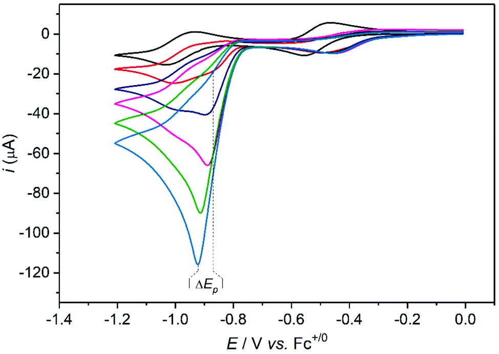 | ||
| Fig. 5 Cyclic voltammograms of Cat1 (2 mM) in CH3CN (+0.1 M nBu4NBF4) recorded at a glassy carbon electrode (1.6 mm diameter) in the presence of various concentrations of p-cyanoanilinium tetrafluoroborate at 100 mV s−1: 0 (black), 4 (red), 8 (navy), 12 (magenta), 16 (green), 20 (cyan) mM. | ||
Based on simulations, Dempsey and coworkers could propose eqn (3) to describe the variation of the catalytic peak potential Ep.39
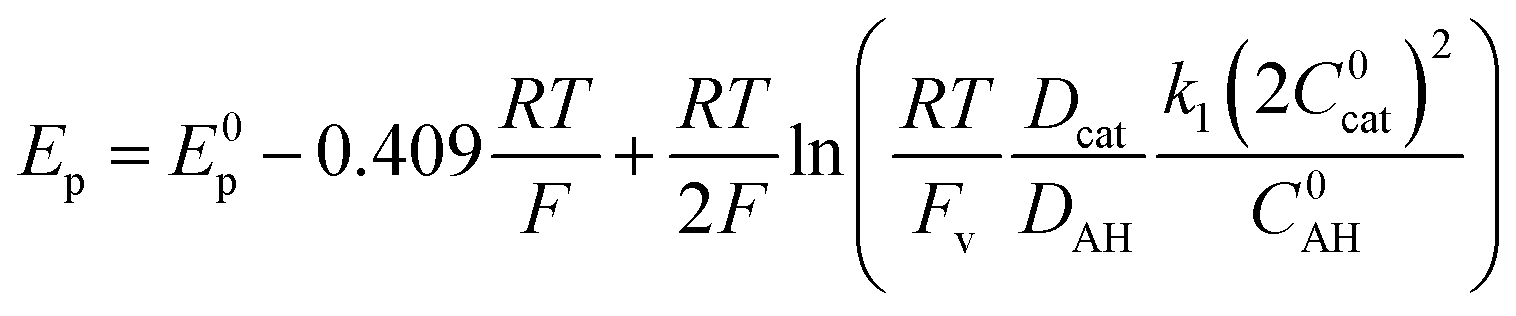 | (3) |
As the intensity of the catalytic wave in the “total catalysis” regime is controlled by the diffusion of the acid, the Dcat/DAH ratio between the diffusion coefficient of the catalyst and p-cyanoanilinium cation can be obtained from the ratio between the catalytic peak current and the current of the monoelectronic CoII/CoI wave measured in the absence of acid, according to eqn (4).
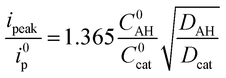 | (4) |
Applying eqn (3) to the data shown in Fig. 5 yields a k1 value of 2.05 ± 0.30 × 10⁴ mol−1 L s−1 for the second order rate constant k1. This value is in good agreement with the one obtained by FOWA although neither k1 nor k2 comply with the condition of being greater than 107 mol−1 L s−1 required for eqn (3) to be valid.39
Interestingly, these data allow ruling out homolytic H2 evolution mediated by Cat1. In such a mechanism, the first protonation step generating the CoIII–H derivative with the k1 rate constant still exists but it is followed by reductive elimination of H2 from two CoIII–H species with a kd second-order rate constant. The linear dependency of the plateau current with the catalyst concentration (Fig. S6‡) rules out homolytic H2 evolution from this CoIII–H derivative in the non-steady state where the rate-determining step is the reductive elimination step.38,40 The identification of two distinct rate constants with k1 being the largest one also allows to rule out steady state homolytic H2 evolution with the rate-determining step being the formation of the CoIII–H derivative, therefore implying that k1 < kd. Finally, while the mechanism proposed in Scheme 1 does not formally exclude that formation of the CoIIIHLH species may proceed through intramolecular protonation of the CoI center of CoILH followed by reprotonation of the ligand, we believe that such a possibility is unlikely as Et3NH+, an acid with a pKa similar to that of the protonated N4H2+ ligand in CoILH, is unable to protonate CoI complexes with similar  value such as [CoI(dmgBF2)2(CH3CN)] (dmgH2 = dimethylglyoxime) in CH3CN.41
The mechanism proposed here for H2 evolution differs from the one proposed by Llobet and Gimbert-Suriñach for aqueous conditions.13,14 First we clearly evidenced that the CoII form of Cat1 is protonated under the conditions investigated here. Ligand protonation also occurs in aqueous electrolyte, as shown by a 59 mV pH unit −1 shift of the redox process reported by Peters and coworkers.19 Second, we propose that H2 is formed from a CoII–H and not a CoIII–H intermediate. We recognize that the electrochemical responses of ECEC and ECCE sequences, both starting from a CoII derivative and implying CoII–H and CoIII–H active species, respectively, are similar. However DFT calculations clearly demonstrated that the standard potential of the CoIII–H/CoII–H is more positive than that of the CoII/CoI couple,13 a feature also observed for cobaloximes and cobalt diimine–dioxime complexes for which the ECEC mechanism is now accepted. Importantly, the mechanism shown in Scheme 1 involves the CoIIHLH species that was proposed by Llobet and Gimbert-Suriñach under photocatalytic conditions,13 therefore unifying the mechanistic understanding of this catalyst. DFT calculations previously indicated a near-thermoneutral intramolecular H2 evolution step from this protonated hydride intermediate.13 Our analysis shows that this step is also the rate-determining one, which explains why catalysis is so fast. Still, the observation that the rate constant of this step is first order in acid concentration suggests that intramolecular H2 formation is coupled with protonation, either in a concerted manner or through kinetic coupling with the fast reprotonation of the amine group of the ligand.
The maximal turnover frequency (TOFmax) of Cat1 therefore approximates k2 × [acid] and a TOFmax value of 5.3 × 10³ s−1 can be extrapolated for 1 M p-cyanoanilinium tetrafluoroborate concentration. Based on this value and an apparent equilibrium potential of the H+/H2 couple of −0.47 V vs. Fc+/Fc at 1 M p-cyanoanilinium tetrafluoroborate concentration and taking homoconjugation into account,26 we could derive the red trace in the catalytic Tafel plot42,43 shown in Fig. 6. Interestingly, Cat1 displays significant catalytic activity (log(TOF/s−1) > 1) at low overpotential values, a property shared by very few other molecular complexes including cobaloximes,42,44 DuBois' nickel bisdiphosphine catalysts42,45 and bis(thiosemicarbazone) cobalt46 and nickel47 complexes. Its overpotential requirement, estimated to be ∼400 mV at the catalytic half-wave potential (and corresponding to the inflexion point in the red catalytic Tafel plot on Fig. 6) is ∼100 mV higher than that of cobaloxime, cobalt diimine–dioxime48 or DuBois' complexes. Importantly, the high TOFmax value also places Cat1 in an intermediate position between cobaloximes and DuBois' complexes, the two champion H2-evolving molecular catalyst series identified so far in non-aqueous solvents.42 It is noteworthy that all three catalysts possess proton relays in their second-coordination sphere and the protonation of these relays is coupled with the metal-centered reduction step that sets the potential of the catalytic wave. The same conclusion can be reached with thiosemicarbazone nickel and cobalt complexes, with ligand-centered reduction occurring in these cases at quite positive potentials.46,47
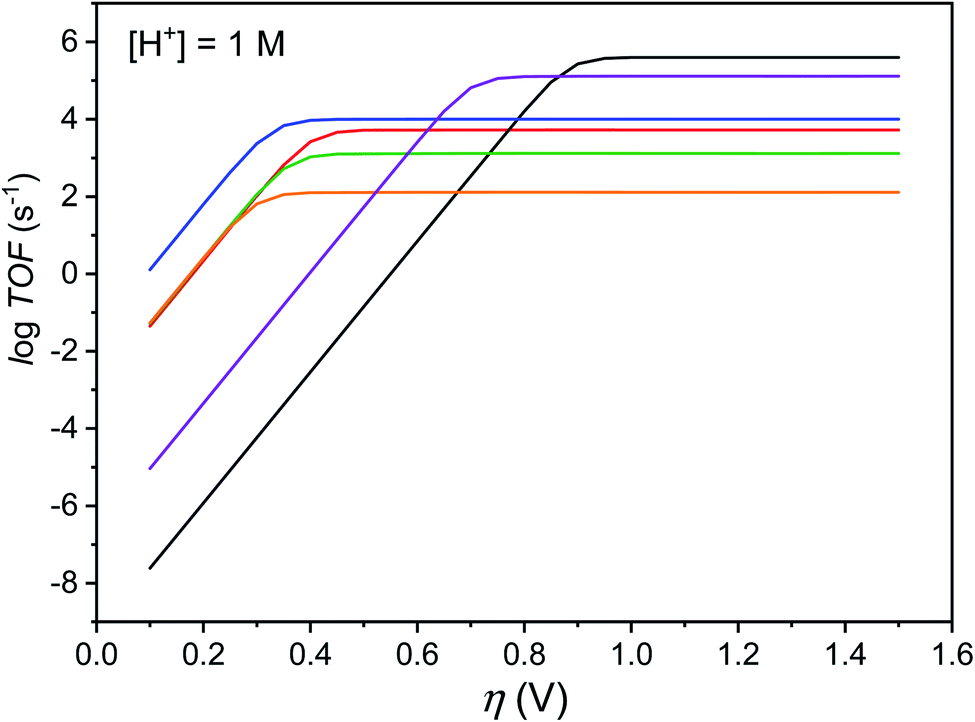 | ||
Fig. 6 Catalytic Tafel plots. Comparison of performances for H2 evolution catalyzed by Cat1 in CH3CN in the presence of 1 M p-cyanoanilinium (red line), with other catalysts reported in the literature: black: FeIITPP, DMF, Et3NH+;42,49 blue: CoII(dmgH)2py, DMF, Et3NH+;42 green: 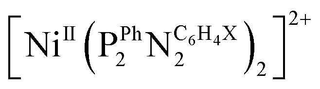 , X = CH2P(O)(OEt)2, MeCN, DMFH+;42,45 orange: 4-{bis[4-(p-methoxyphenyl)thiosemicarbazone]}-2,3-butane cobalt, DMF, Et3NH+;46 purple: [CoII(bapbpy)Cl], DMF, Et3NH+.23 , X = CH2P(O)(OEt)2, MeCN, DMFH+;42,45 orange: 4-{bis[4-(p-methoxyphenyl)thiosemicarbazone]}-2,3-butane cobalt, DMF, Et3NH+;46 purple: [CoII(bapbpy)Cl], DMF, Et3NH+.23 | ||
Conclusions
While Cat1 is becoming more and more popular as a molecular H2-evolving catalyst for the design of aqueous systems, it is increasingly important to advance the understanding of its H2 evolution catalysis mechanism13 and performance by providing insight into the catalytic steps involved. This is especially the case when considering structural modification50 or molecular engineering51 in order to either enhance catalytic activity or stability16 or immobilise a catalytic centre for integration in photoelectrodes7–9 or devices. In the societal context, both of these objectives are ultimately necessary to achieve industrial relevancy and technological maturity of hydrogen-producing electrolysers based on molecular catalysts made from earth-abundant elements.2,4In this study, new EPR evidence for the structure of the CoII state of the catalyst and its dependence on the presence and nature of the acid has been presented, as well as NMR and cyclic voltammetry data indicating that fast protonation of the ligand occurs at the CoII stage. Carrying on from previous work in the literature,13,14,22 these results reconcile mechanisms at play under electrochemical and photochemical conditions. Furthermore, a proper utilisation of the most advanced analytical methods available for molecular catalysis of electrochemical reactions has allowed definitively ruling out a homolytic H2 evolution mechanism and substantiated the proposed heterolytic ECEC mechanism, for which the rate constants for the two successive protonation steps could be determined. The rate-determining step has been confirmed as the intramolecular H2 evolution step, surmised to be coupled to the second protonation, thereby regenerating a protonated ligand and thus acting as a proton relay in catalysis,32 which, interestingly, is at variance with the behaviour of the dioxime bridge in cobalt diimine–dioxime complexes.48 Catalytic Tafel plots could be derived to enable the benchmarking of the H2 evolution performance of Cat1 alongside other highly efficient catalysts and confirm its place on the podium.
Conflicts of interest
There are no conflicts to declare.Acknowledgements
This work received funding from the French National Research Agency (Labex ARCANE, CBH-EUR-GS, ANR-17-EURE-0003), the European Research Council and European Commission's Seventh Framework Program (FP7/2007–2013) under grant agreement no. 306398 (project PhotocatH2ode), the European Union's Horizon 2020 Research and Innovation program under grant agreement no. 765376 (eSCALED Marie Curie ITN project). C-B. L. acknowledges support from the Chinese Scientific Council for a post-doctoral scholarship.References
- V. Artero, M. Chavarot-Kerlidou and M. Fontecave, Angew. Chem., Int. Ed., 2011, 50, 7238–7266 CrossRef CAS.
- J. R. McKone, S. C. Marinescu, B. S. Brunschwig, J. R. Winkler and H. B. Gray, Chem. Sci., 2014, 5, 865–878 RSC.
- N. Queyriaux, R. T. Jane, J. Massin, V. Artero and M. Chavarot-Kerlidou, Coord. Chem. Rev., 2015, 304–305, 3–19 CrossRef CAS PubMed.
- L. Tong, L. Duan, A. Zhou and R. P. Thummel, Coord. Chem. Rev., 2020, 402, 213079 CrossRef CAS.
- V. S. Thoi, Y. J. Sun, J. R. Long and C. J. Chang, Chem. Soc. Rev., 2013, 42, 2388–2400 RSC.
- J. L. Karn and D. H. Busch, Nature, 1966, 211, 160–162 CrossRef CAS.
- S. Bold, J. Massin, E. Giannoudis, M. Koepf, V. Artero, B. Dietzek and M. Chavarot-Kerlidou, ACS Catal., 2021, 11, 3662–3678 CrossRef CAS.
- C. Nie, W. Ni, L. Gong, J. Jiang, J. Wang and M. Wang, J. Mater. Chem. A, 2019, 7, 27432–27440 RSC.
- C. Nie, C. Liu, L. Gong and M. Wang, J. Mater. Chem. A, 2021, 9, 234–238 RSC.
- R. Gueret, C. E. Castillo, M. Rebarz, F. Thomas, A. A. Hargrove, J. Pecaut, M. Sliwa, J. Fortage and M. N. Collomb, J. Photochem. Photobiol., B, 2015, 152, 82–94 CrossRef CAS PubMed.
- S. Varma, C. E. Castillo, T. Stoll, J. Fortage, A. G. Blackman, F. Molton, A. Deronzier and M. N. Collomb, Phys. Chem. Chem. Phys., 2013, 15, 17544–17552 RSC.
- C. Gimbert-Surinach, J. Albero, T. Stoll, J. Fortage, M. N. Collomb, A. Deronzier, E. Palomares and A. Llobet, J. Am. Chem. Soc., 2014, 136, 7655–7661 CrossRef CAS PubMed.
- S. Grau, M. Schilling, D. Moonshiram, J. Benet-Buchholz, S. Luber, A. Llobet and C. Gimbert-Suriñach, ChemSusChem, 2020, 13, 2745–2752 CrossRef CAS PubMed.
- D. Moonshiram, C. Gimbert-Suriñach, A. Guda, A. Picon, C. S. Lehmann, X. Zhang, G. Doumy, A. M. March, J. Benet-Buchholz, A. Soldatov, A. Llobet and S. H. Southworth, J. Am. Chem. Soc., 2016, 138, 10586–10596 CrossRef CAS.
- C. H. Lee, D. Villagran, T. R. Cook, J. C. Peters and D. G. Nocera, ChemSusChem, 2013, 6, 1541–1544 CrossRef CAS PubMed.
- M. Sandroni, R. Gueret, K. D. Wegner, P. Reiss, J. Fortage, D. Aldakov and M. N. Collomb, Energy Environ. Sci., 2018, 11, 1752–1761 RSC.
- R. Gueret, L. Poulard, M. Oshinowo, J. Chauvin, M. Dahmane, G. Dupeyre, P. P. Laine, J. Fortage and M. N. Collomb, ACS Catal., 2018, 8, 3792–3802 CrossRef CAS.
- S. Roy, M. Bacchi, G. Berggren and V. Artero, ChemSusChem, 2015, 8, 3632–3638 CrossRef CAS.
- C. C. L. McCrory, C. Uyeda and J. C. Peters, J. Am. Chem. Soc., 2012, 134, 3164–3170 CrossRef CAS.
- N. Kaeffer, A. Morozan, J. Fize, E. Martinez, L. Guetaz and V. Artero, ACS Catal., 2016, 6, 3727–3737 CrossRef CAS.
- V. Artero and M. Fontecave, Chem. Soc. Rev., 2013, 42, 2338–2356 RSC.
- C. F. Leung, Y. Z. Chen, H. Q. Yu, S. M. Yiu, C. C. Ko and T. C. Lau, Int. J. Hydrogen Energy, 2011, 36, 11640–11645 CrossRef CAS.
- N. Queyriaux, D. Y. Sun, J. Fize, J. Pecaut, M. J. Field, M. Chavarot-Kerlidou and V. Artero, J. Am. Chem. Soc., 2020, 142, 274–282 CrossRef CAS PubMed.
- C. Römelt, T. Weyhermüller and K. Wieghardt, Coord. Chem. Rev., 2019, 380, 287–317 CrossRef.
- A. M. Appel, S. J. Lee, J. A. Franz, D. L. DuBois, M. R. DuBois and B. Twamley, Organometallics, 2009, 28, 749–754 CrossRef CAS.
- V. Fourmond, P. A. Jacques, M. Fontecave and V. Artero, Inorg. Chem., 2010, 49, 10338–10347 CrossRef CAS.
- J. Niklas, K. L. Mardis, R. R. Rakhimov, K. L. Mulfort, D. M. Tiede and O. G. Poluektov, J. Phys. Chem. B, 2012, 116, 2943–2957 CrossRef CAS PubMed.
- T. Arcos, B. de Castro, M. J. Ferreira, M. Rangel and J. B. Raynor, J. Chem. Soc., Dalton Trans., 1994, 369–377 RSC.
- A. Bakac and J. H. Espenson, J. Am. Chem. Soc., 1984, 106, 5197–5202 CrossRef CAS.
- A. Bhattacharjee, E. S. Andreiadis, M. Chavarot-Kerlidou, M. Fontecave, M. J. Field and V. Artero, Chem.–Eur. J., 2013, 19, 15166–15174 CrossRef CAS.
- J. M. Savéant, Elements of Molecular and Biomolecular Electrochemistry, Wiley, 2006 Search PubMed.
- J. M. Saveant, Angew. Chem., Int. Ed., 2019, 58, 2125–2128 CrossRef CAS.
- J. M. Saveant and K. B. Su, J. Electroanal. Chem., 1984, 171, 341–349 CrossRef CAS.
- A. F. M. M. Rahman, W. G. Jackson, A. C. Willis and A. D. Rae, Chem. Commun., 2003, 2748–2749 RSC.
- J.-W. Wang, K. Yamauchi, H.-H. Huang, J.-K. Sun, Z.-M. Luo, D.-C. Zhong, T.-B. Lu and K. Sakai, Angew. Chem., Int. Ed., 2019, 58, 10923–10927 CrossRef CAS.
- R. Gueret, C. E. Castillo, M. Rebarz, F. Thomas, M. Sliwa, J. Chauvin, B. Dautreppe, J. Pécaut, J. Fortage and M.-N. Collomb, Inorg. Chem., 2019, 58, 9043–9056 CrossRef CAS.
- C. Costentin, S. Drouet, M. Robert and J.-M. Savéant, J. Am. Chem. Soc., 2012, 134, 11235–11242 CrossRef CAS.
- C. Costentin and J.-M. Savéant, ChemElectroChem, 2014, 1, 1226–1236 CrossRef CAS.
- E. S. Rountree, D. J. Martin, B. D. McCarthy and J. L. Dempsey, ACS Catal., 2016, 6, 3326–3335 CrossRef CAS.
- C. Costentin, H. Dridi and J.-M. Savéant, J. Am. Chem. Soc., 2014, 136, 13727–13734 CrossRef CAS.
- C. Baffert, V. Artero and M. Fontecave, Inorg. Chem., 2007, 46, 1817–1824 CrossRef CAS.
- V. Artero and J.-M. Saveant, Energy Environ. Sci., 2014, 7, 3808–3814 RSC.
- C. Costentin, S. Drouet, M. Robert and J. M. Saveant, Science, 2012, 338, 90–94 CrossRef CAS.
- M. Razavet, V. Artero and M. Fontecave, Inorg. Chem., 2005, 44, 4786–4795 CrossRef CAS.
- U. J. Kilgore, J. A. S. Roberts, D. H. Pool, A. M. Appel, M. P. Stewart, M. R. DuBois, W. G. Dougherty, W. S. Kassel, R. M. Bullock and D. L. DuBois, J. Am. Chem. Soc., 2011, 133, 5861–5872 CrossRef CAS PubMed.
- T. Straistari, R. Hardre, J. Fize, S. Shova, M. Giorgi, M. Reglier, V. Artero and M. Orio, Chem.–Eur. J., 2018, 24, 8779–8786 CrossRef CAS.
- T. Straistari, J. Fize, S. Shova, M. Réglier, V. Artero and M. Orio, ChemCatChem, 2016, 2262–2268 Search PubMed.
- D. Sun, A. K. Harshan, J. Pecaut, S. Hammes-Schiffer, C. Costentin and V. Artero, Chemelectrochem, 2021, 8, 2671–2679 CrossRef CAS.
- I. Bhugun, D. Lexa and J. M. Saveant, J. Am. Chem. Soc., 1996, 118, 3982–3983 CrossRef CAS.
- W. X. Nie, D. E. Tarnopol and C. C. L. McCrory, J. Am. Chem. Soc., 2021, 143, 3764–3778 CrossRef CAS.
- N. Coutard, N. Kaeffer and V. Artero, Chem. Commun., 2016, 52, 13728–13748 RSC.
Footnotes |
| † In memory of Dr Jean-Michel Savéant. |
| ‡ Electronic supplementary information (ESI) available. See DOI: 10.1039/d1se01267c |
| § Equal contribution. |
| This journal is © The Royal Society of Chemistry 2022 |